RainUs G2000 Gateway User Manual
RainUs Co., Ltd. Gateway
UserManual.wiki
>
RainUs
>
G2000 User Manual
User Manual
Navigation menu
Upload a User Manual
Namespaces
Wiki Guide
HTML
PDF
Info
Views
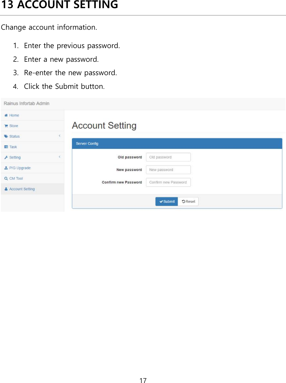
User Manual
Discussion / Help
Navigation