User Manual

1
Gateway-G2000
USER’s MANUAL
Version 1.3
2018
2
Contents
1 G2000 Introduction ............................................................................................................................... 3
2 G2000 Product release & preparing to install ...................................................................................... 3
2-1 G2000 Product release ....................................................................................................................... 3
2-2 G2000 Power supply & Check operation ........................................................................................ 4
3 HOME .................................................................................................................................................... 6
4 STORE .................................................................................................................................................... 6
5 GATEWAY STATUS ................................................................................................................................. 7
6 TAG STATUS .......................................................................................................................................... 8
7 TASK ...................................................................................................................................................... 9
8 SERVER CONFIG ................................................................................................................................... 10
9 STORE CONFIG .................................................................................................................................... 11
10 GATEWAY CONFIG ........................................................................................................................... 12
11 P/G UPGRADE ................................................................................................................................... 13
12 CONFIGURATION TOOL .................................................................................................................... 15
13 ACCOUNT SETTING ........................................................................................................................... 17

3
1 G2000 INTRODUCTION
G2000 communicates with ESLs through IEEE802.15.4 RF transceivers and interfaces
with ESL server.
2 G2000 PRODUCT RELEASE & PREPARING TO INSTALL
2-1 G2000 PRODUCT RELEASE
▶ Package of the product.
▶ 4 Dipole antennas are coupled to the G2000 Reverse-SMA connectors.
( Caution : Antenna can be damaged if excessive force is applied. when the Reverse-SMA
connector is coupled to the antenna if the antenna can cause damage , if left for a

4
long time at a low temperature after coupling takes damage to the antenna fixing
portion. )
2-2 G2000 POWER SUPPLY & CHECK OPERATION
▶ Insert the RJ45 (PoE) Connector on the G2000 PoE Connector.
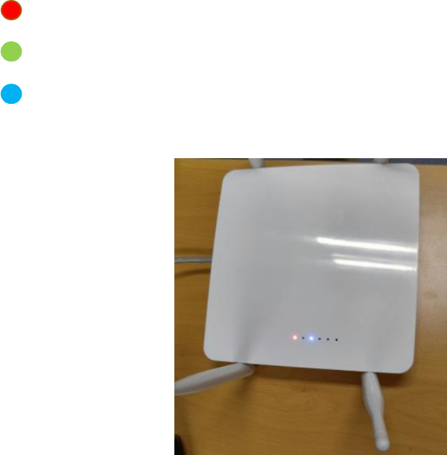
5
▶ Check the LED
RED : DC 5V power is applied.
GREEN : Operation MCU
BLUE : Operation Ethernet
6
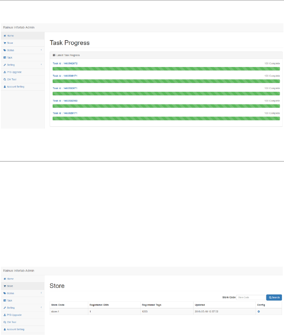
3 HOME
It shows the progress of recent work.
4 STORE
Displays a list of registered stores.
The output information is as follows.
⚫ Store code
⚫ Number of installed Gateways
⚫ Number of installed Tags(InforTab)
Click the icon of Configure item to go to setting page.
7
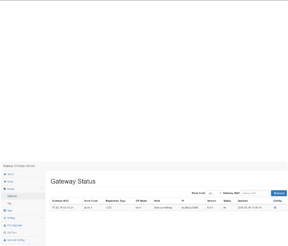
5 GATEWAY STATUS
Displays the status information of the Gateway.
The output information is as follows.
⚫ Gateway MAC address
⚫ Store code
⚫ Number of registered Tags
⚫ Operation mode
⚫ IP address
⚫ Version information
⚫ Status informaiton
Click the icon of Configure item to go to setting page.
8
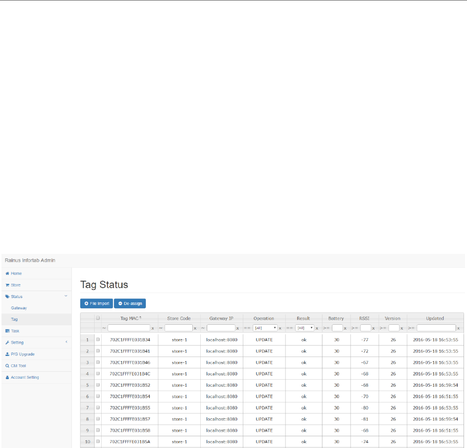
6 TAG STATUS
Displays the status information of the Tags
The output information is as follows.
⚫ Tags MAC address
⚫ Store code
⚫ Connected Gateway IP address
⚫ The last work done
⚫ Work result
⚫ Battery
⚫ Received signal strength
⚫ Version information
9
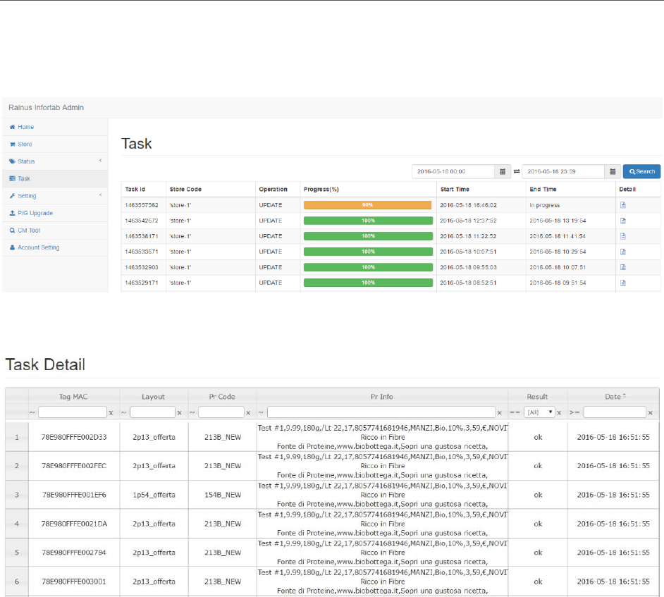
7 TASK
Show progress of work.
You can click the icon of the detail item to see the details of the operation.
Here are the details of the work.
10
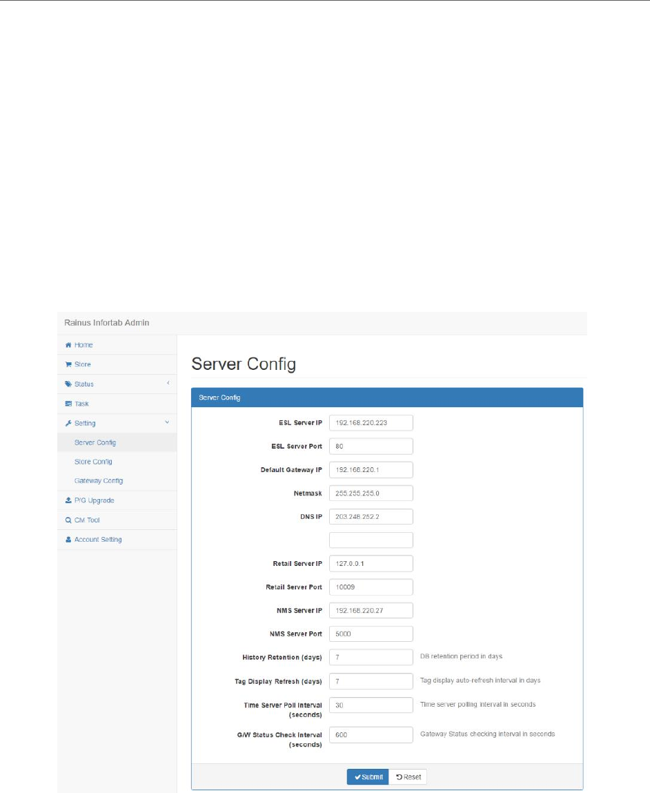
8 SERVER CONFIG
Modify server configuration information.
The input information is as follows.
⚫ Server network information
⚫ Retail Server IP address and Port
⚫ NMS Server IP address and Port
⚫ Data retention period
⚫ Tag refresh cycle
⚫ NTP server synchronization cycle
⚫ Gateway status reporting cycle
11
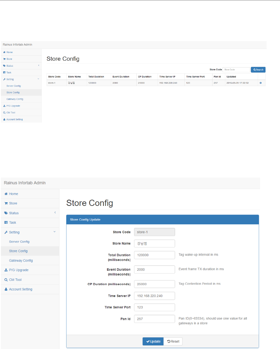
9 STORE CONFIG
Displays a list of registered store settings information.
Click the icon of the config item to go to the settings page.
The following is the screen to modify store information.
⚫ Store name
⚫ NTP server information
12
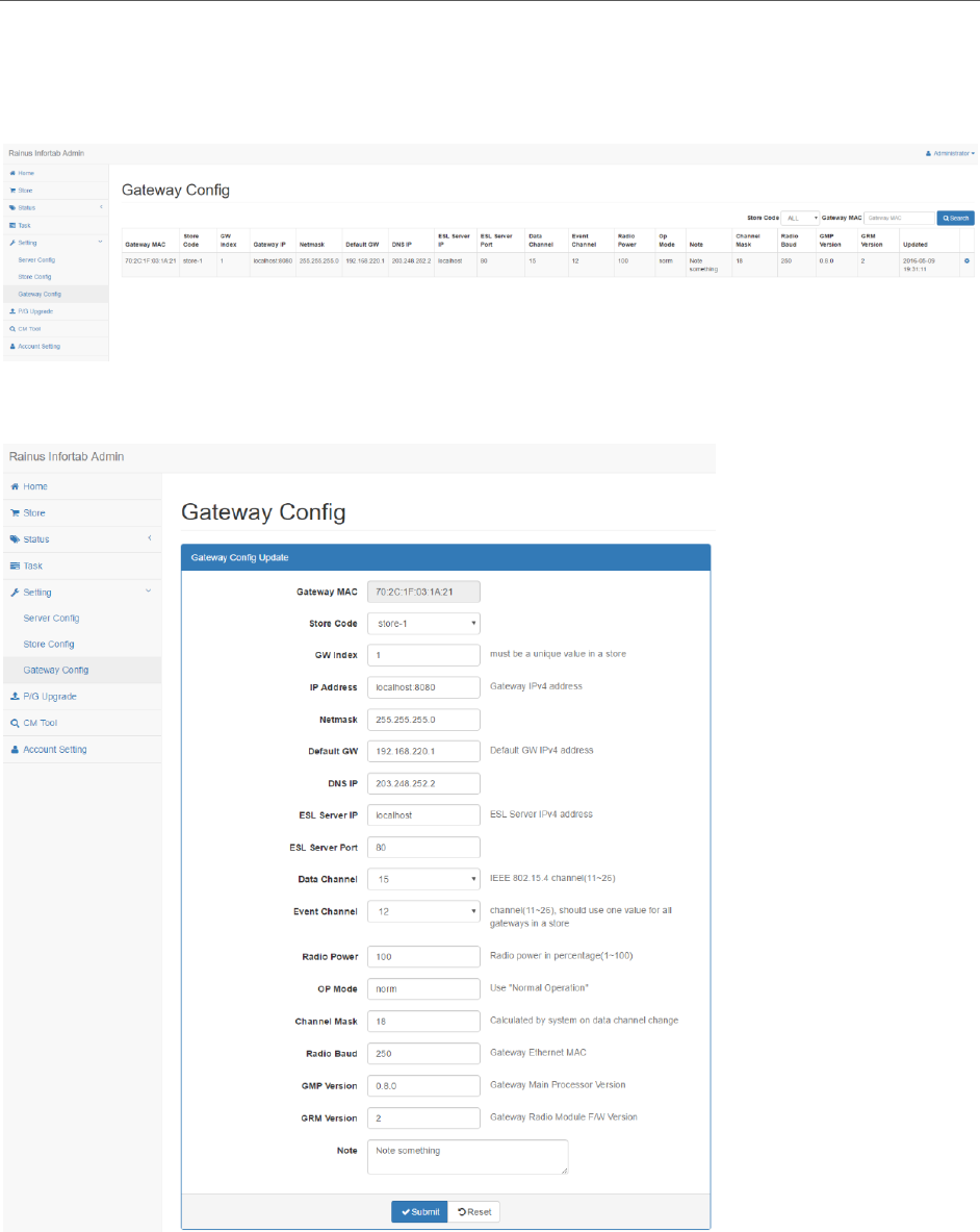
10 GATEWAY CONFIG
Show list of registered store information.
Click the icon of the config item to go to the settings page.
The following is the gateway configuration information modification screen.
13
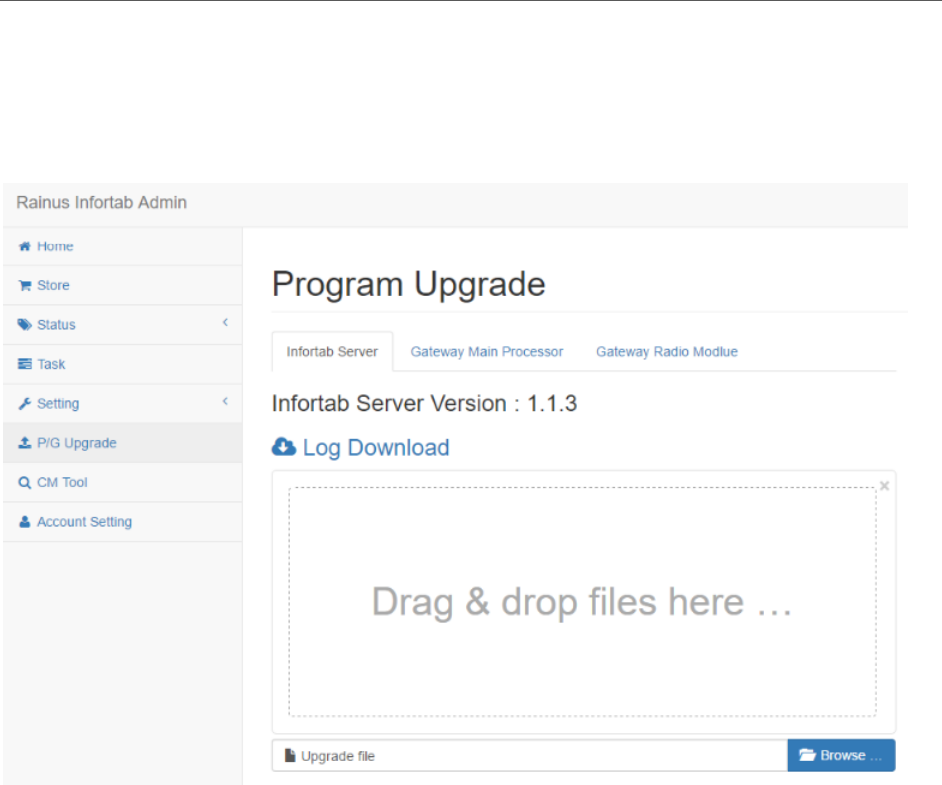
11 P/G UPGRADE
If the version of the server and the gateway program are changed, the upgrade can
be performed by uploading the corresponding file.
Here is the program upgrade screen on the server.
14
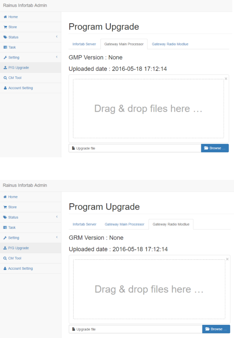
The following is the gateway main processor program upgrade screen.
The following is the program upgrade screen of the gateway wireless module.
15
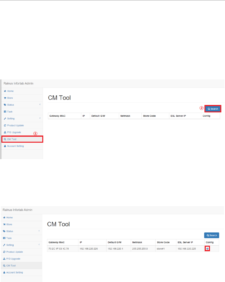
12 CONFIGURATION TOOL
Search the gateway installed in the store and change the network-related
configuration information.
Place the gateway on the same network as the server.
Select the CM Tool menu on the left side and click the Search button on the right
side.
When the screen for the gateway is complete, the results are output as a list.
Click the settings icon on the right.
16
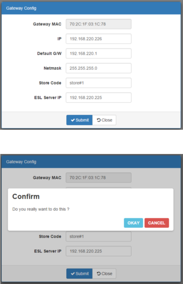
Enter the setup information and click the Submit button.
Click the Okay button.
17
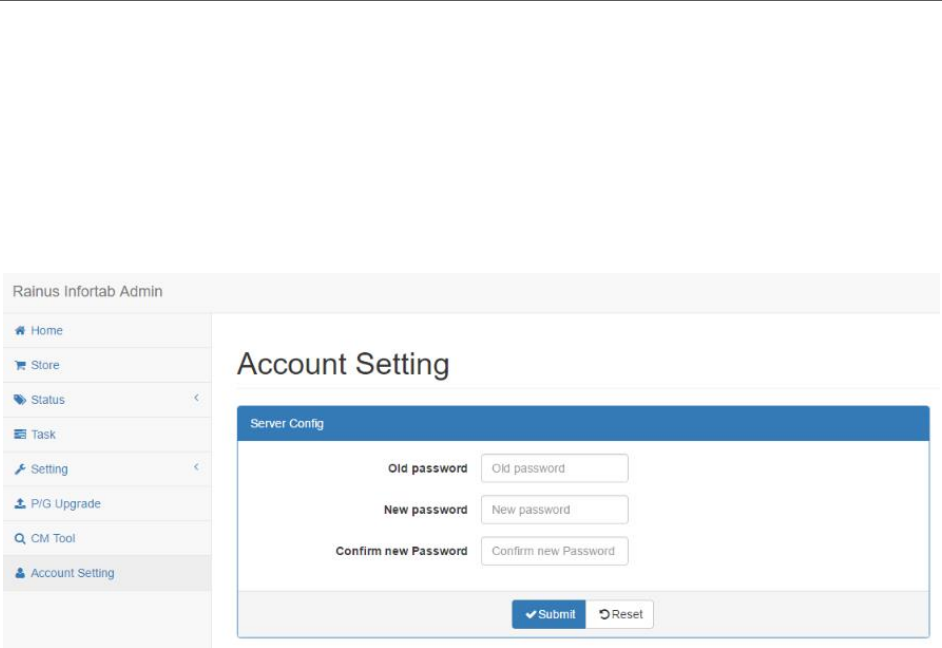
13 ACCOUNT SETTING
Change account information.
1. Enter the previous password.
2. Enter a new password.
3. Re-enter the new password.
4. Click the Submit button.
18
WARNING
This device complies with part 15 of the FCC Rules. Operation is subject to the
following two conditions:
(1) This device may not cause harmful interference, and
(2) This device must accept any interference received, including interference that
may cause undesired operation.
CAUTION
Any changes or modifications to the equipment not expressly approved by the
party responsible for compliance could void user’s authority to operate the
equipment.
This appliance and its antenna must not be co-located or operation in
conjunction with any other antenna or transmitter.
A minimum separation distance of 20cm must be maintained between the
antenna and the person for this appliance to satisfy the RF exposure
requirements.