Ranger Communications TR-286 AM/SSB CB Transceiver User Manual
Ranger Communications (M) SDN. BHD. AM/SSB CB Transceiver Users Manual
UserManual.wiki
>
Ranger Communications
>
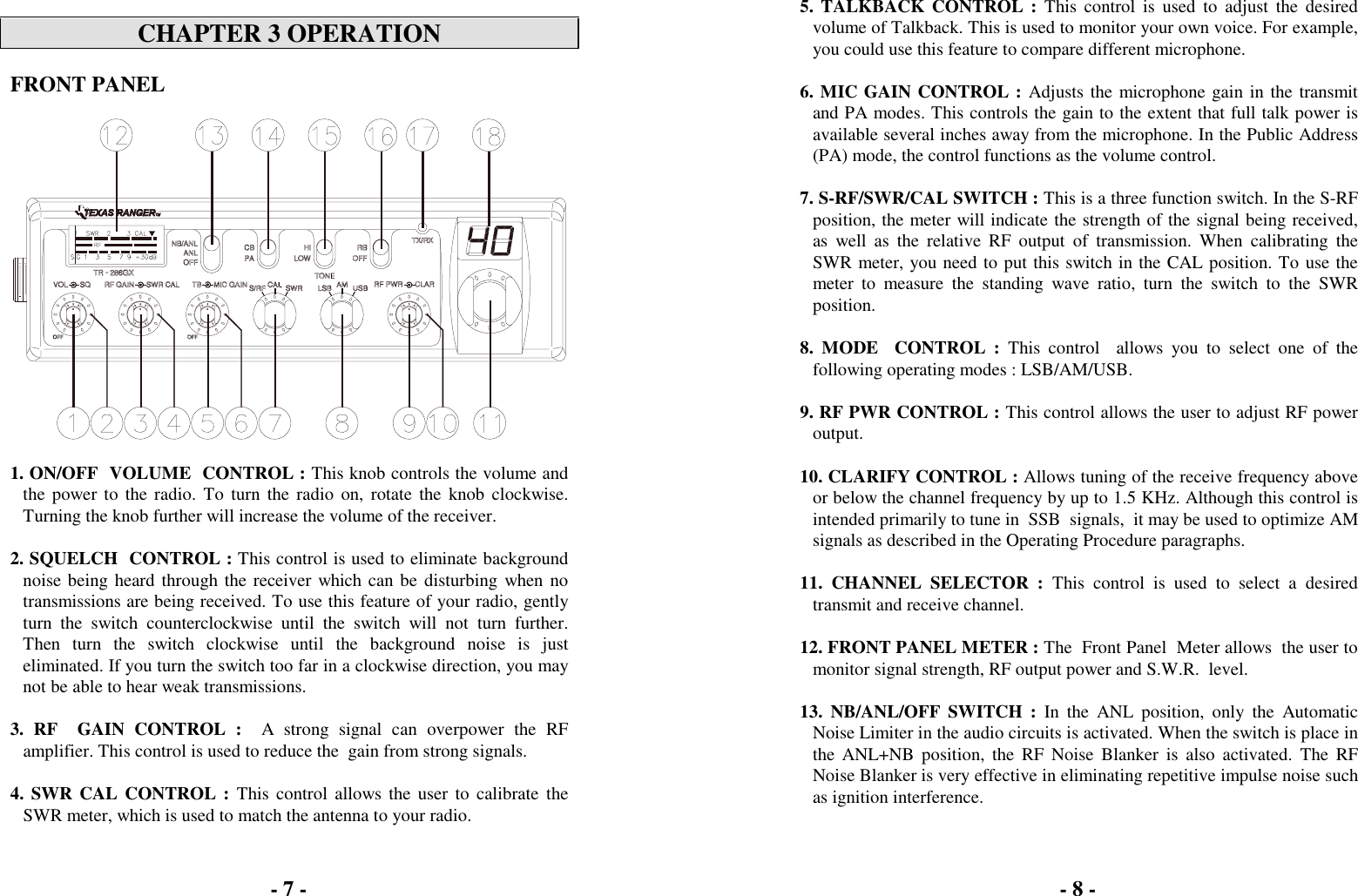
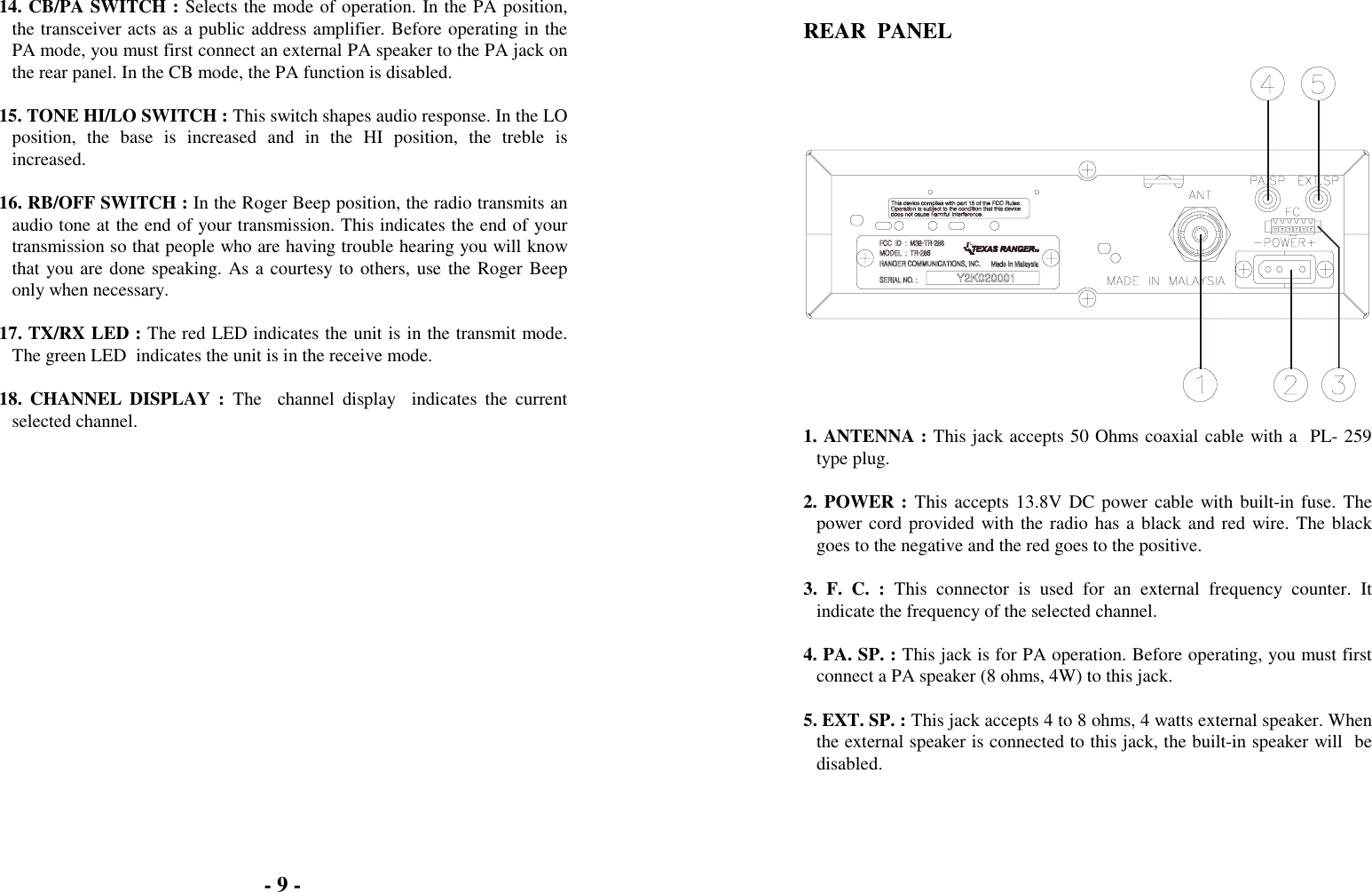
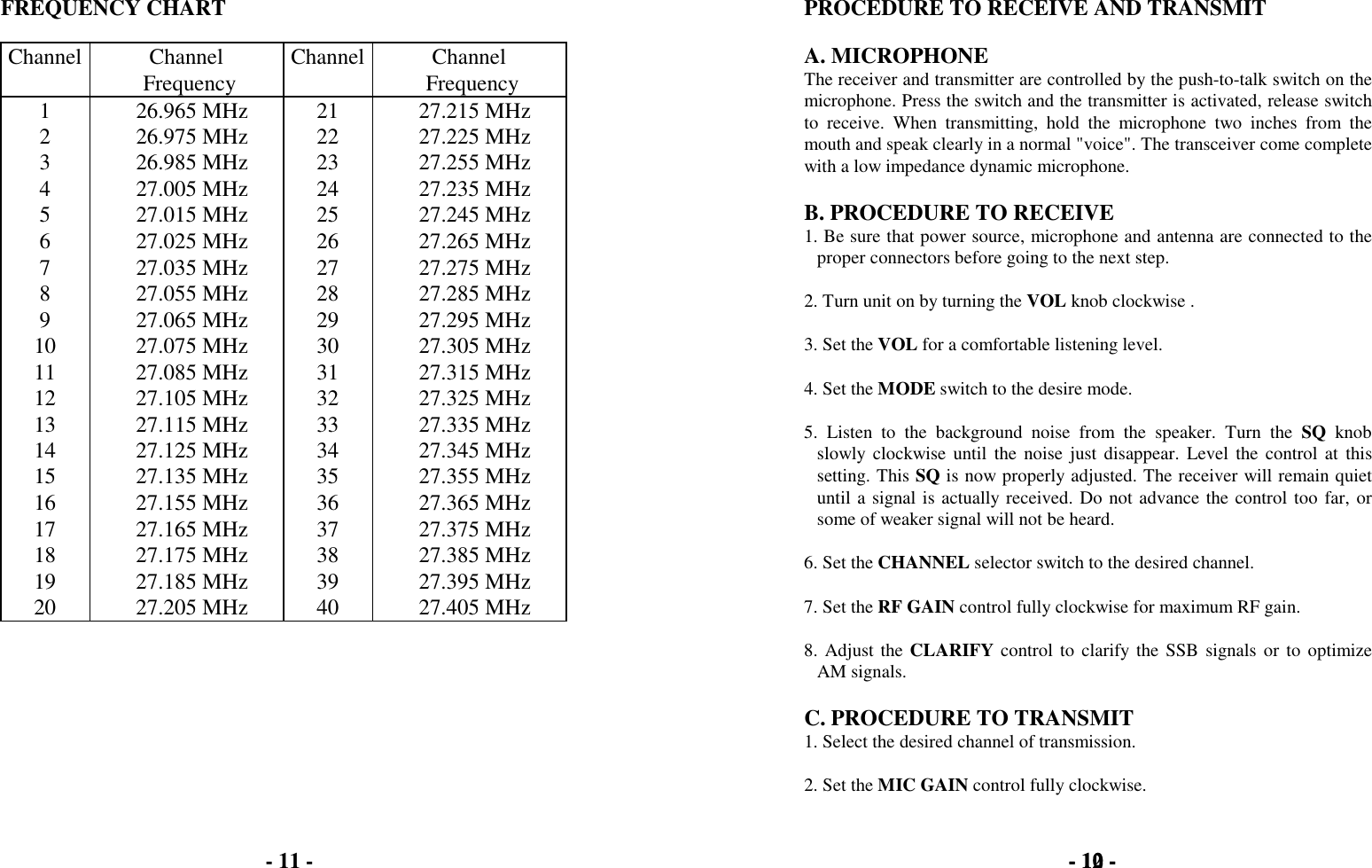
TR 286 User Manual
Users Manual
Navigation menu
Upload a User Manual
Namespaces
Wiki Guide
HTML
PDF
Info
Views
User Manual
Discussion / Help
Navigation