Ray Allen FSERIES TACTICAL K9 DEPLOYMENT HEAT ALERT SYSTEM AND PAGER User Manual
Ray Allen Manufacturing Company, Inc TACTICAL K9 DEPLOYMENT HEAT ALERT SYSTEM AND PAGER Users Manual
UserManual.wiki
>
Ray Allen
>
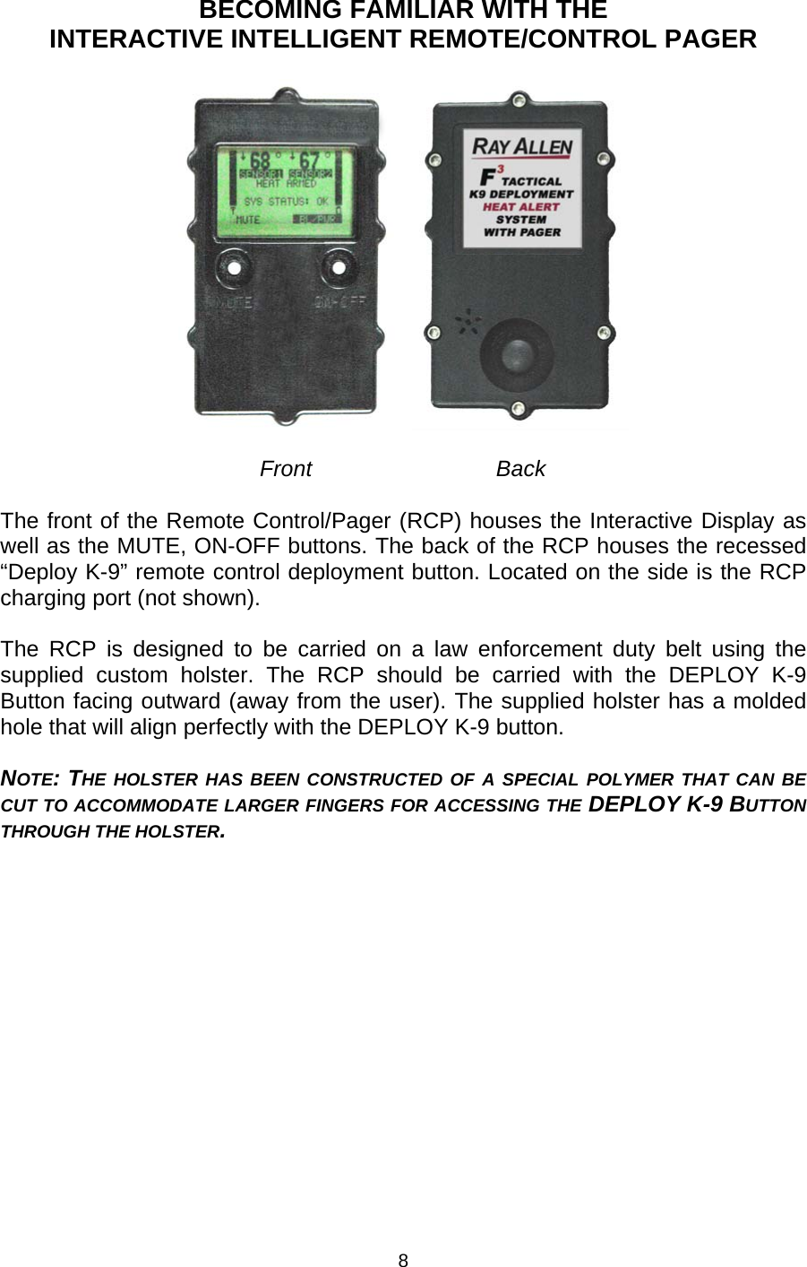
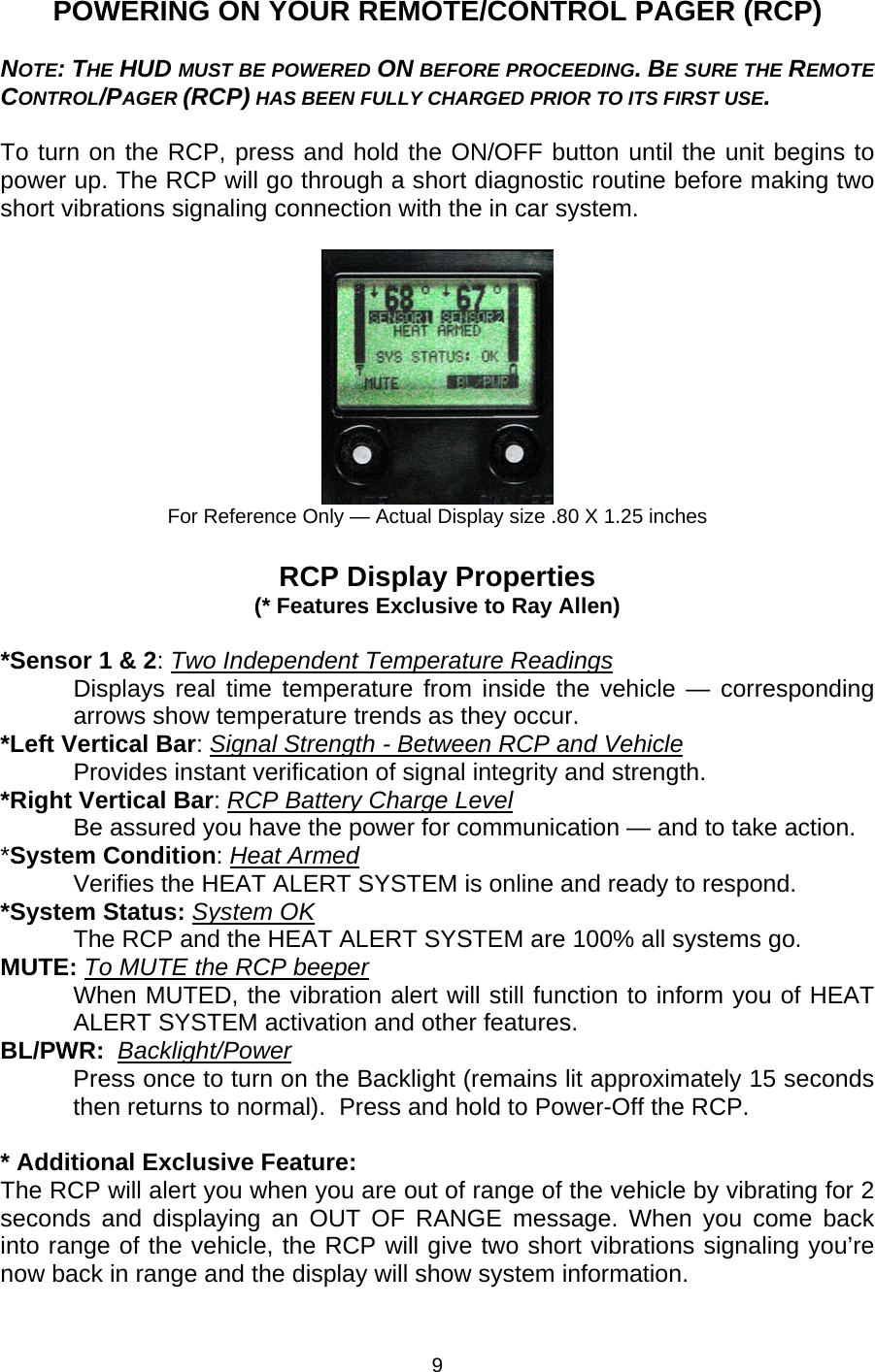
FSERIES User Manual
Users Manual
Navigation menu
Upload a User Manual
Namespaces
Wiki Guide
HTML
PDF
Info
Views
User Manual
Discussion / Help
Navigation