Rayence RY1012WCA Medical Image Processing Unit User Manual
Rayence Co., Ltd. Medical Image Processing Unit User Manual
UserManual.wiki
>
Rayence
>
RY1012WCA User Manual
User_Manual
Navigation menu
Upload a User Manual
Namespaces
Wiki Guide
HTML
PDF
Info
Views
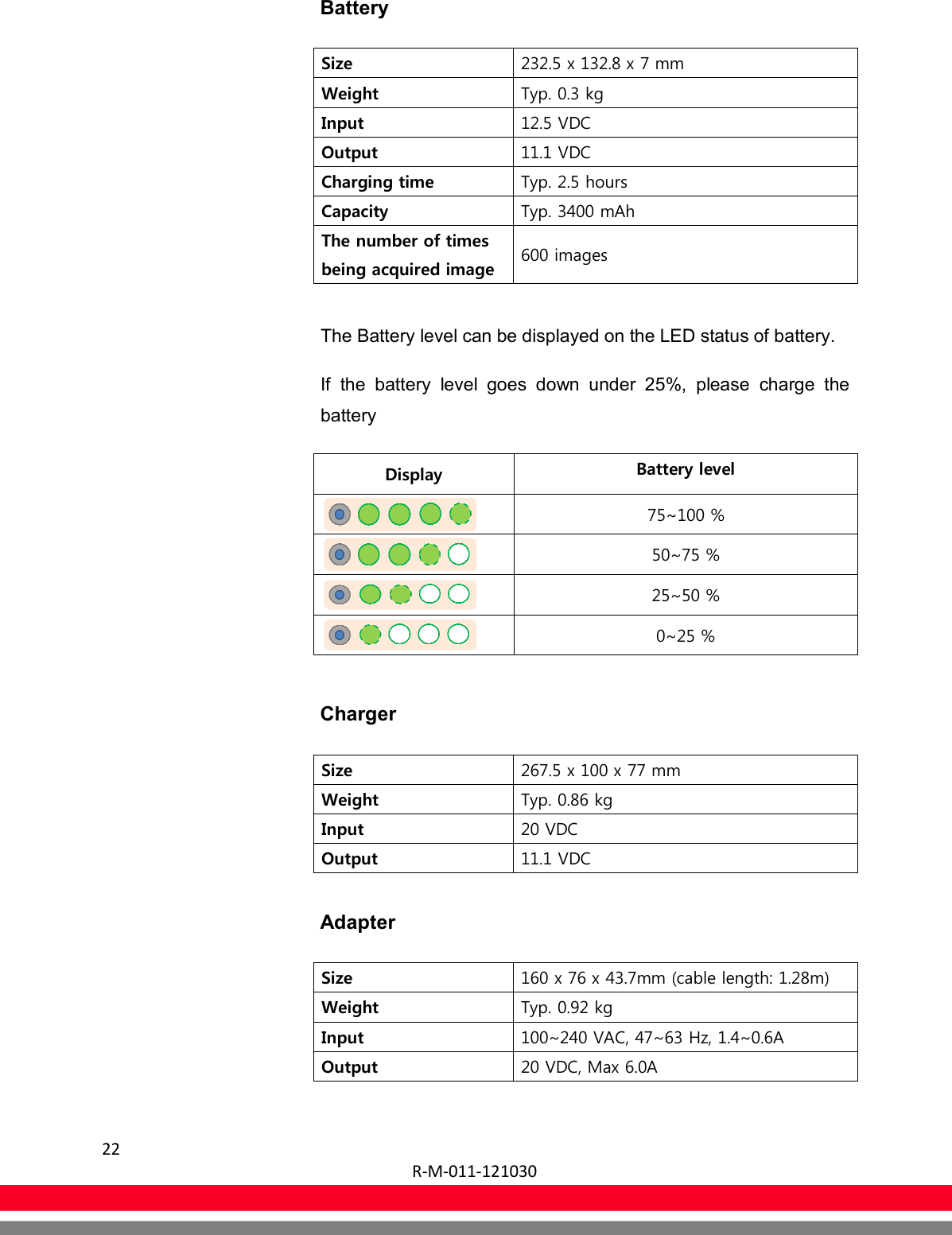
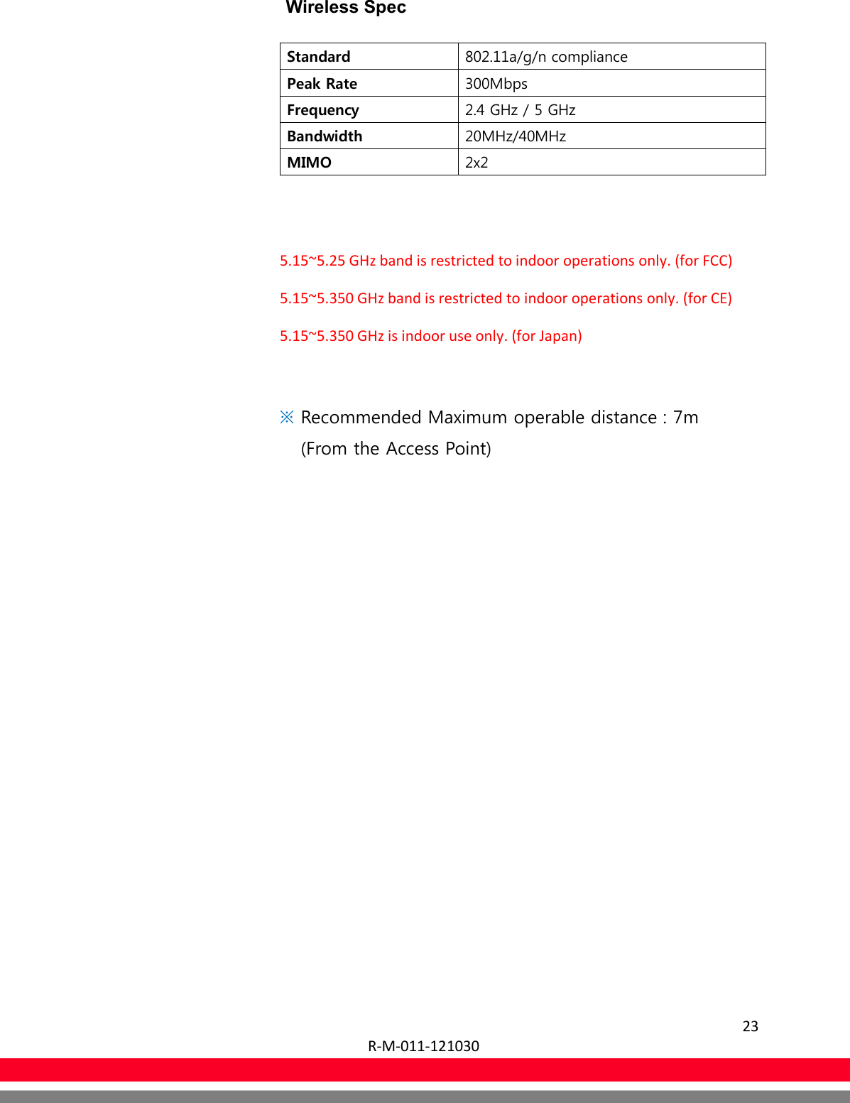
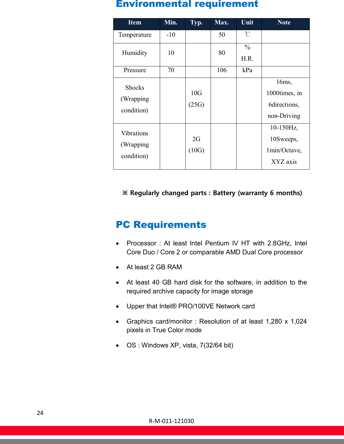
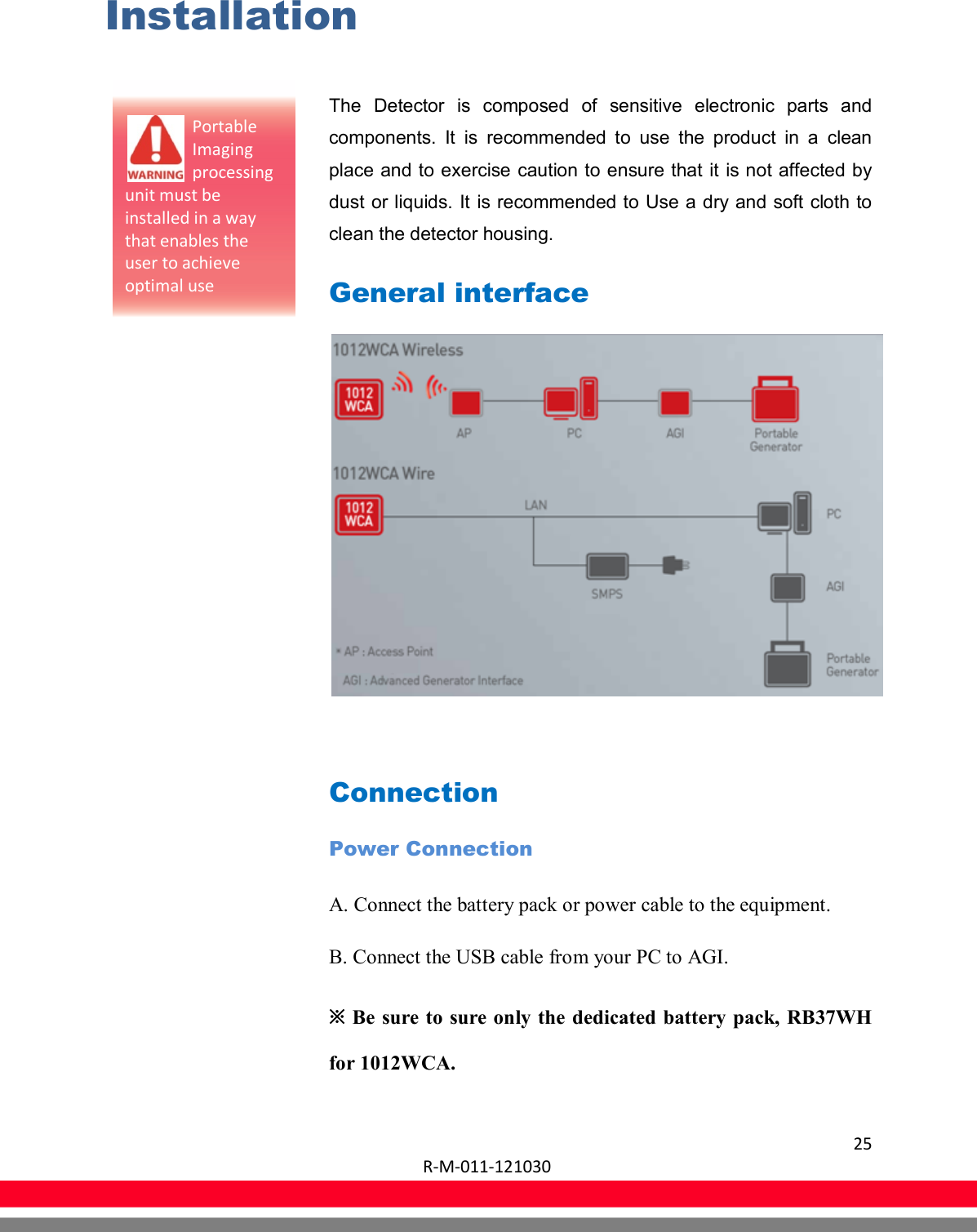
User Manual
Discussion / Help
Navigation
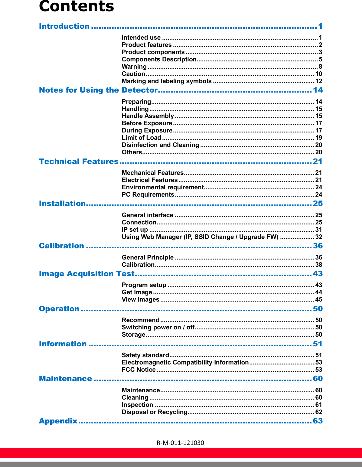

![31 R-M-011-121030 IP set up [My Network Places] → [Properties] → [Local Area Connection] → [Properties] → [Internet Protocol (TCP/IP)] → [Use the following IP address] IP address : Obtain an IP address automatically IP address : Obtain an IP address automatically](https://usermanual.wiki/Rayence/RY1012WCA/User-Guide-1890798-Page-35.png)