Rayence RY1012WCA Medical Image Processing Unit User Manual
Rayence Co., Ltd. Medical Image Processing Unit User Manual
Rayence >
User_Manual
Release Version 1.0.6
Medical Image Processing Unit
1012WCA
User Manual

R-M-011-121030
© Copyright 2012, Rayence Co. Ltd.
All pages of this document contain proprietary and confidential
information of Rayence Corporation and are intended for exclusive use
by Rayence Corporation personnel or customers. Copying, disclosure to
others or other use is prohibited without the express written
authorization from Rayence Corporation. Please report any violations of
requirement to Rayence Corporation.
R
-
M
-
011
-
121030
Attention
For improvement of product performance, supplementation, or follow-up of information; the
contents of this manual are subject to change without separate prior notice.
Please note that our company has neither responsibility for any accidents nor obligation to
do free repair service for any damage of the equipment due to user's mistake, which resulted
from failure to follow the contents in this manual. Make sure to be familiar with the safety
precautions and usage procedures. Also note that the product may slightly differ from the
contents of this manual depending on specification.
The following marks are used for the effective use of the product in this manual.
Attention, consult accompanying documents.
This is used to emphasize essential information. Be sure to read this
information to avoid incorrect operation.
This indicates hazardous situation which, if not heeded, may result in
minor or moderate injury to you or others, or may result in machine
damage.
This indicates a potentially hazardous situation which, if not heeded, could
result in death or serious injury to you or others.
Federal Law restricts this device to sale by or the order of a radiologist or
any other practitioners licensed by the law of the state in which that
person practices to use or order the use of the device.

R-M-011-121030
Contents
Introduction ........................................................................................ 1
Intended use ...................................................................................... 1
Product features ................................................................................ 2
Product components ......................................................................... 3
Components Description................................................................... 5
Warning .............................................................................................. 8
Caution ............................................................................................. 10
Marking and labeling symbols ........................................................ 12
Notes for Using the Detector ............................................................ 14
Preparing .......................................................................................... 14
Handling ........................................................................................... 15
Handle Assembly ............................................................................. 15
Before Exposure .............................................................................. 17
During Exposure .............................................................................. 17
Limit of Load .................................................................................... 19
Disinfection and Cleaning ............................................................... 20
Others ............................................................................................... 20
Technical Features ........................................................................... 21
Mechanical Features ........................................................................ 21
Electrical Features ........................................................................... 21
Environmental requirement ............................................................. 24
PC Requirements ............................................................................. 24
Installation........................................................................................ 25
General interface ............................................................................. 25
Connection ....................................................................................... 25
IP set up ........................................................................................... 31
Using Web Manager (IP, SSID Change / Upgrade FW) ................... 32
Calibration ........................................................................................ 36
General Principle ............................................................................. 36
Calibration ........................................................................................ 38
Image Acquisition Test ..................................................................... 43
Program setup ................................................................................. 43
Get Image ......................................................................................... 44
View Images ..................................................................................... 45
Operation .......................................................................................... 50
Recommend ..................................................................................... 50
Switching power on / off .................................................................. 50
Storage ............................................................................................. 50
Information ....................................................................................... 51
Safety standard ................................................................................ 51
Electromagnetic Compatibility Information .................................... 53
FCC Notice ....................................................................................... 53
Maintenance ..................................................................................... 60
Maintenance ..................................................................................... 60
Cleaning ........................................................................................... 60
Inspection ........................................................................................ 61
Disposal or Recycling...................................................................... 62
Appendix ........................................................................................... 63

1
R
-
M
-
011
-
121030
Introduction
Overview
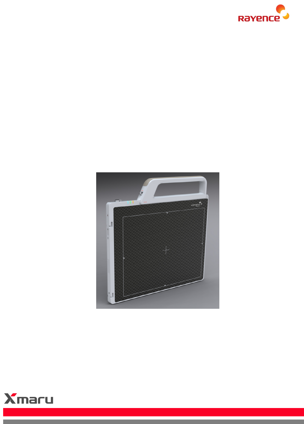
The 1012WCA is a wireless digital X-ray flat panel detector that
can generate images of any part of the body. The wireless
LAN((IEEE 802.11a/g/n) communication feature improves the
operability, and high-speed processing. This X-ray imaging
system consists of a scintillator directly coupled to an a-Si TFT
sensor. It makes high-resolution, high-sensitive digital images.
Intended use
For U.S.A.
1012WCA Digital Flat Panel X-Ray Detector is indicated for
digital imaging solution designed for human anatomy including
head, neck, spinal column, arm, leg and peripheral (foot, hand,
wrist, fingers, etc.). It is intended to replace film based
radiographic diagnostic systems and provide a case diagnosis
and treatment planning for physicians and other health care
professionals. Not to be used for mammography.
For European Union
This device provides digital X-ray imaging for diagnosis of
disease, injury, or any applicable health problem. The image is
obtained as the result of imaging X-rays passed through the
human body with an X-ray flat panel detector and importing a
digital signal output from the detector into the image processor.
2
R-M-011-121030
Product features
Wi-Fi (802.11a/g/n)
Based on a-Si TFT active matrix
Compact (18mm thickness) and light weight (Typ. 3.15kg)
Limiting Resolution : 3.9 lp/mm
16-bit digital output
Easy integration
3
R
-
M
-
011
-
121030
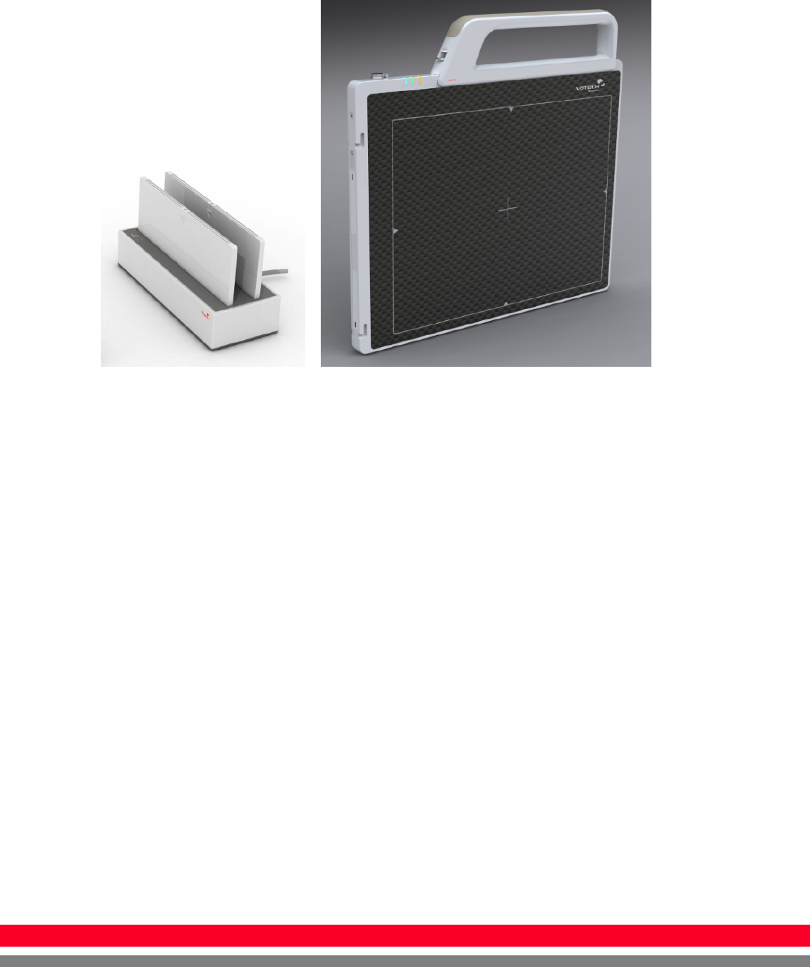
Product components
Medical Image Processing Unit
Photo
Item
Part Name
Quantity
Detector SD1012WCA 1
Handle - 1
Battery pack RB37WH 2
Battery charger RC120W 1
Charger adapter
PMP120-13-3 1
AGI RA001A 1
4
R-M-011-121030
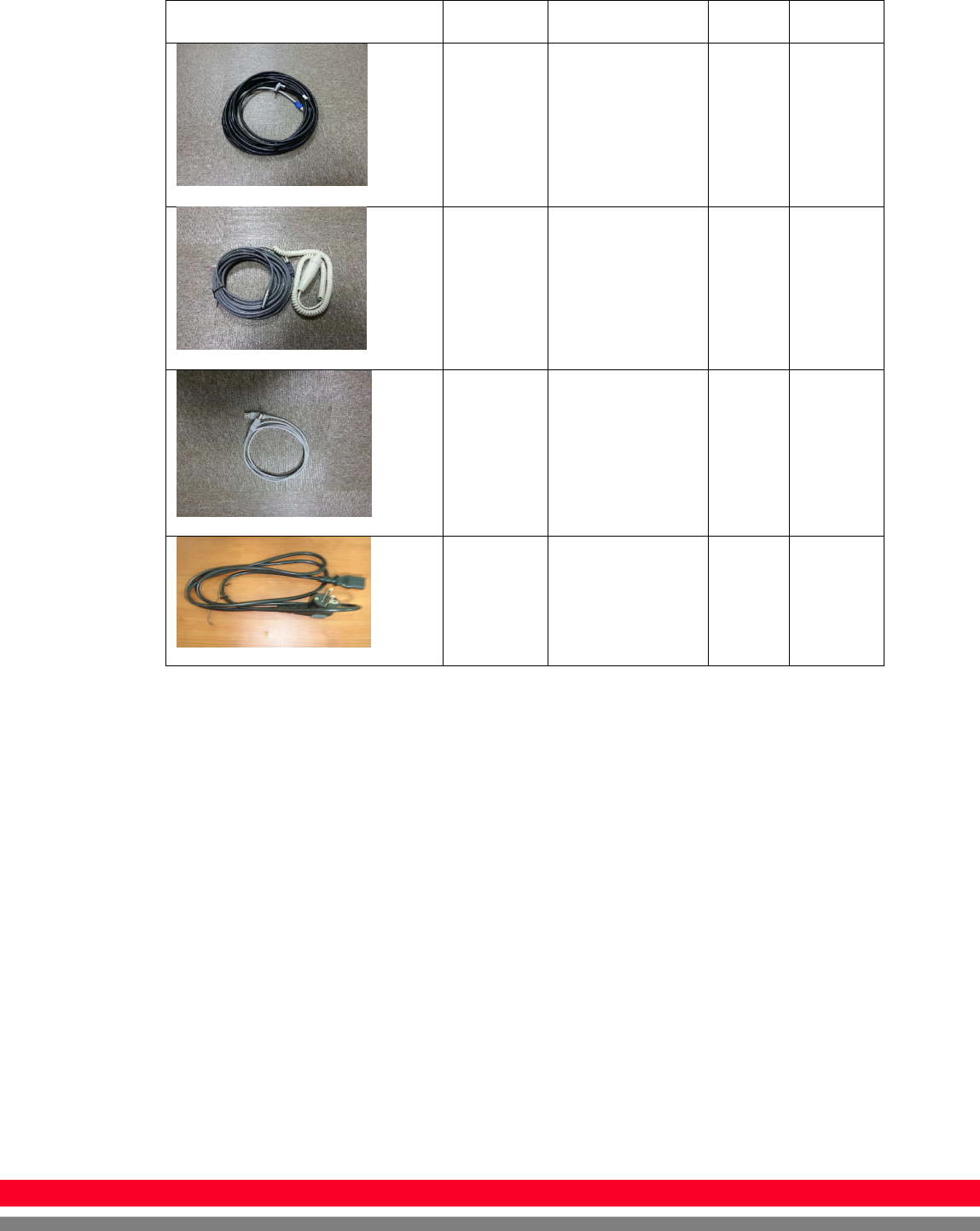
Cables
Item
Part Name
Length
Quantity
Link cable
VRH076A 6m 1
P-
Interface
cable
VRH017A 8m 1
USB
cable (A
to B)
VRH078A 1.8m 1
AC Power
cord VRH018A/019A 1.8m 1
Installation CD
o Manual
o Detector Library
Option
o Additional Battery
o Charger for the Car
o Cover Bag
o AP package
5
R
-
M
-
011
-
121030
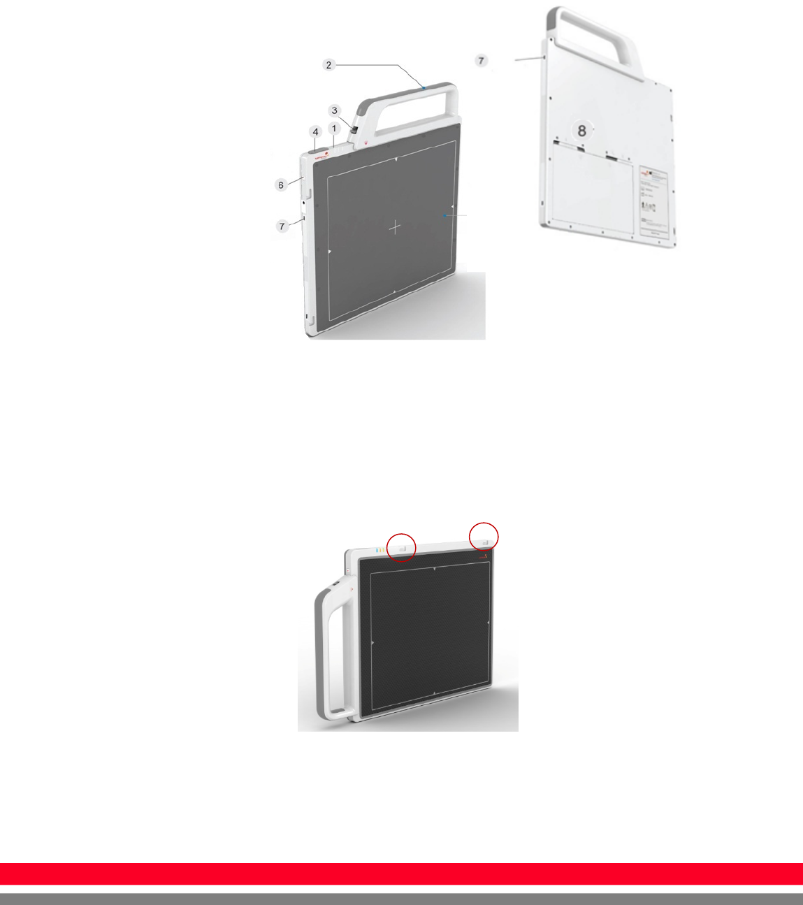
Components Description
The detector is designed to capture radiographic images.
Captured images are transmitted to PC using the wireless/wired
connection.
(1) Detector
1. LED indicator: The LED indicates the state of detector.
i. Green on : Power on.
ii. Blue blinking : Wireless Connection.
iii. Orange on : Low battery.
2. Handle : Hold this handle when carrying the sensor unit. It is
removable. (Horizon / Vertical)
3. Handle unlock-lever : This is an unlock-lever to remove handle.
4. Link cable connector : This is a connector for Wire communication

6
R-M-011-121030
and power supplying. Connect the detector to PC and SMPS(not
provided) using Link cable.
5. CFRP(Carbon Fiber Reinforced Plastic) : The part of the patient’s
body to which an image is to be taken should be placed against this
plate.
6. Power button : Power on / Power off switch.
7. Shock sensor : Detector has built-in 4 Shock sensors. It detects
and records impact and mishandling of fragile
8. Battery unlock-lever : This is an unlock-lever to remove battery.
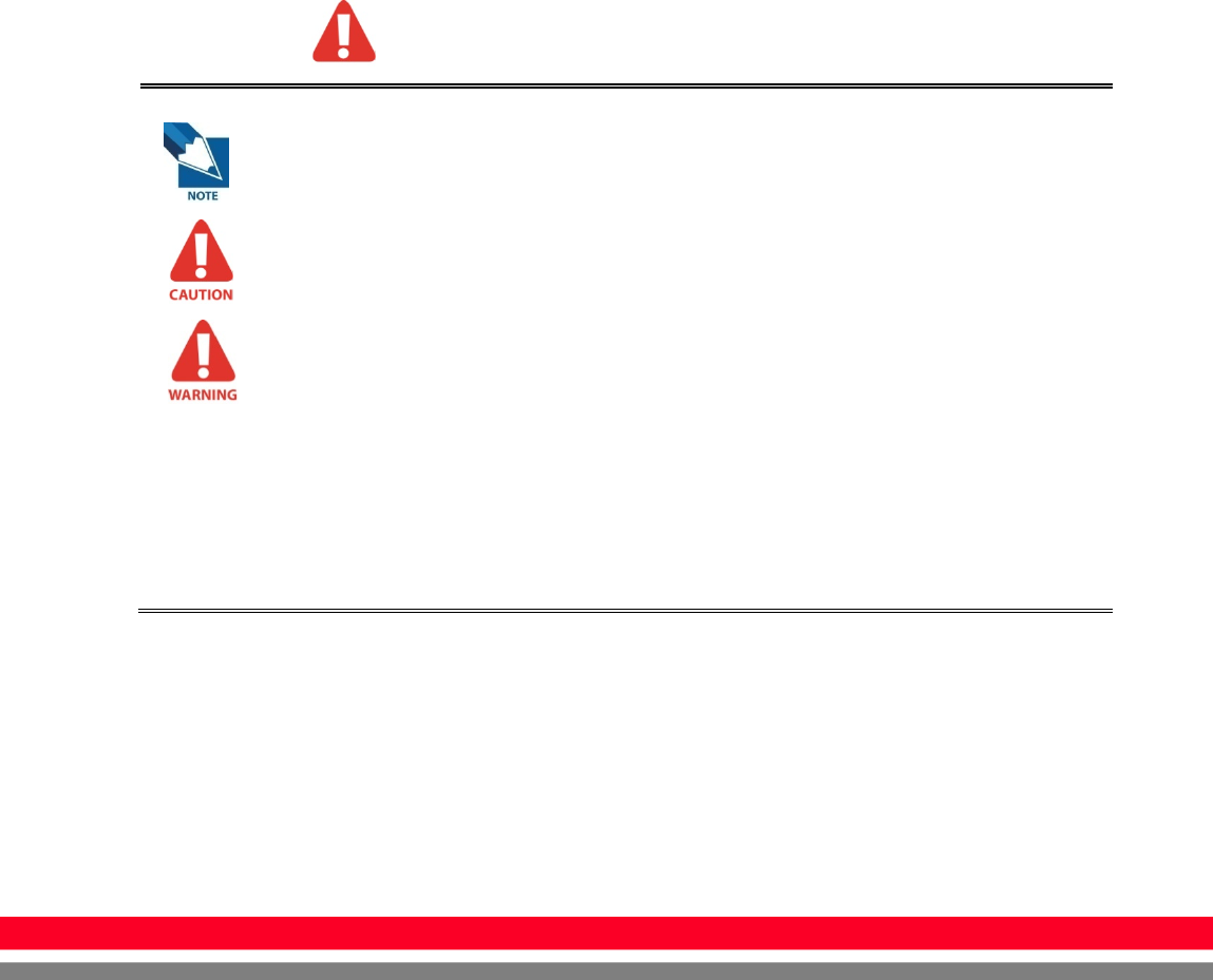
(2) Battery & Charger
1. Battery : Lithium ion battery. The number of times being acquired
image is 600 images(@ cycle time : 15s). The batteries last 2.5
hours and are rechargeable.
2. Charger : Two port cradle type.
3. LED indicator :
i. Orange on : charging
ii. Green on : Charging is completed.

7
R
-
M
-
011
-
121030
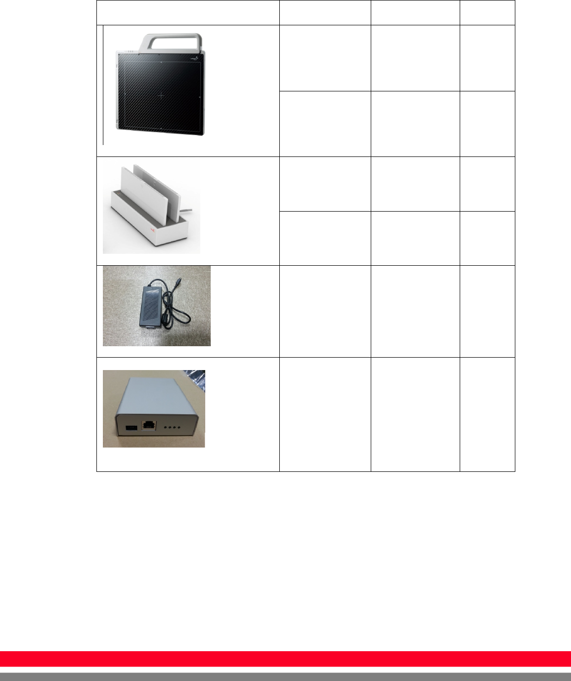
(3) AGI
1. Trigger connector: This is a connector for synchronization
between detector and generator. Connect the AGI to the generator
using P-interface cable..
2. USB connector: This is a connector for communication between
AGI and PC. Connect the AGI to the PC using USB cable.

8
R-M-011-121030
Warning
Environment of Use and Storage
Follow the specified process of operational instructions written in
this manual for the safety of the users and patients.
Does not use or store the instrument near any flammable
chemicals such as thinner, benzene, etc. Also, this instrument is
not a category AP or APG equipment. If chemicals are spilled or
evaporate, it may result in fire or electric shock through contact
with electric parts inside the instruments. Also, some
disinfectants are flammable. Be sure to take care when using
them.
Connection
Do not connect the instrument with anything other than specified.
Otherwise, it may result in fire or electric shock.
Handling
Always be sure to keep checking the condition of the system and
the patient to ensure they are normal during the use of the
instrument. If any problem is found, take appropriate measures,
such as stopping the operation of the instrument, as required.
Never disassemble or modify the product as it may result in fire
or electric shock. Also, since the instrument incorporates parts
that may cause electric shocks and other hazardous parts,
touching them may cause death or serious injury.
Do not hit or drop the instrument. The instrument may be
damaged if it receives a strong jolt, which may result in fire or
electric shock if the instrument is used without being repaired.
Make sure
to observe
the following right

9
R
-
M
-
011
-
121030
When Problem Occurs
Should any of the following occur, immediately turn OFF the
power of each instruments, unplug the power supply cord from
the AC outlet, and contact Rayence representative or distributor.
When there is smoke, odd smell or abnormal sound.
When liquid has been spilled into the instrument or a metal
object has entered through an opening.
When the instrument has been dropped and it is damaged.
Maintenance and Inspection
For safety reasons, be sure to turn OFF the power of each
instrument when the inspections indicated in this manual are
going to be performed. Otherwise, it may result in electric shock.
When the instrument is going to be cleaned, be sure to turn OFF
the power of each instrument, and unplug the power supply cord
from the AC outlet.
The instrument must be repaired by a qualified engineer only. If it
is not repaired properly, it may cause fire, electric shock, or
accident.
Make sure
to observe
the following right.

10
R-M-011-121030
Caution
Environment of Use and Storage
Do not install the instrument in a location with the conditions
listed below. Otherwise, it may result in failure or malfunction,
cause fire or injury.
Close to facilities where water is used.
Where it will be exposed to direct sunlight.
Close to air-conditioner or ventilation equipment.
Close to heat source such as a heater.
Prone to vibration.
Insecure place.
Dusty environment.
Saline or sulfurous environment.
High temperature or humidity.
Freezing or condensation.
Do not place the storage case in a location with the conditions
listed below.
Where the cable of the sensor unit will be strongly pulled
when the sensor unit is put into the case, otherwise, the cable
may be damaged, resulting in fire or electric shock.
Where someone might get their foot caught in the cable of the
sensor unit. Otherwise they could trip over, resulting in injury

11
R
-
M
-
011
-
121030
Handling
Do not spill liquid or chemicals onto the instrument or, in cases
where the patient is injured, allow it to become wet with blood or
other body fluids, as doing so may result in fire or electric shock.
In such situation, protect the instrument with disposable covering
as necessary.
Wipe the CFRP plate of the sensor unit with ethanol or
glutaraldehyde solution to disinfect it each time a different patient
uses the instrument, in order to prevent infection.
Turn off the power of each instrument for safety when they are
not going to be used.
Maintenance and Inspection
For safety reasons, be sure to inspect the instrument before
using it. In addition, carry out a regular inspection at least once a
year.
Modifications
Any changes or modifications in construction of this device which
are not expressly approved by the party responsible for
compliance could void the user's authority to operate the
equipment.
12
R-M-011-121030
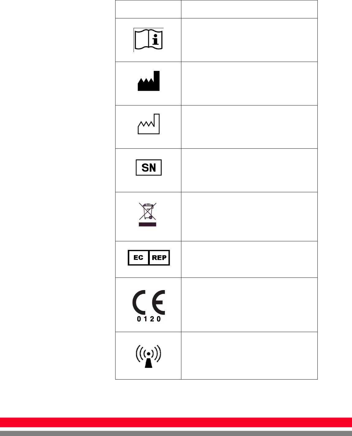
Marking and labeling symbols
Symbols Meaning
Caution : “Attention, see instructions for use”
Manufacturer
Date of manufacture
Serial number
WEEE : Waste Electrical and Electronic
Equipment
Authorized representative in the European
Community
CE symbol grants the product compliance to
the European Directive for Medical Devices
93/42/EEC as a class Ⅱa device. Authorized by
Notified Body SGS (code no.:0120) of British
non-ionizing radiation
13
R
-
M
-
011
-
121030
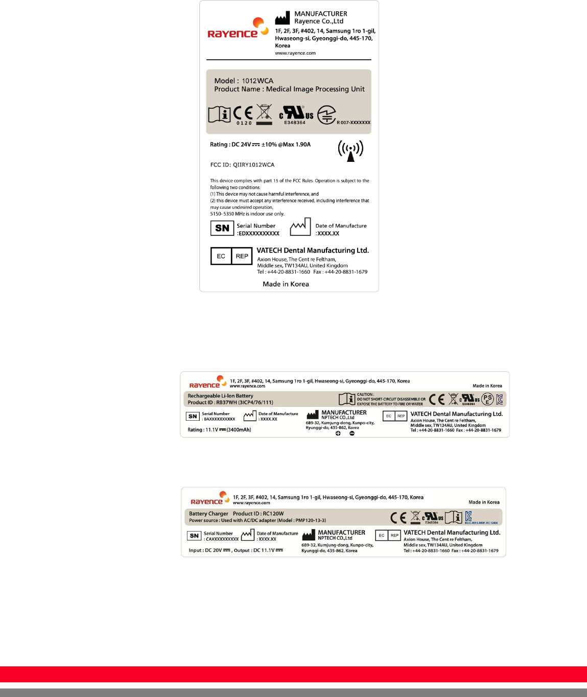
Labels
Detector label
Battery Pack
Battery Charger
14
R-M-011-121030
Notes for Using the Detector
Preparing
Fully charge the battery pack. Charge the battery on the day of
examination or on the previous day.
Battery slowly discharges even of not in use. The battery
pack may have expired if it discharges immediately after
being fully charged. You can purchase an optional battery
pack to replace an exhausted one.
Be sure to fully charge the battery before use.
※ The battery charger, RC120W is designed for the
dedicated battery pack.
※ When the detector will not be used for some time, remove
the battery pack.
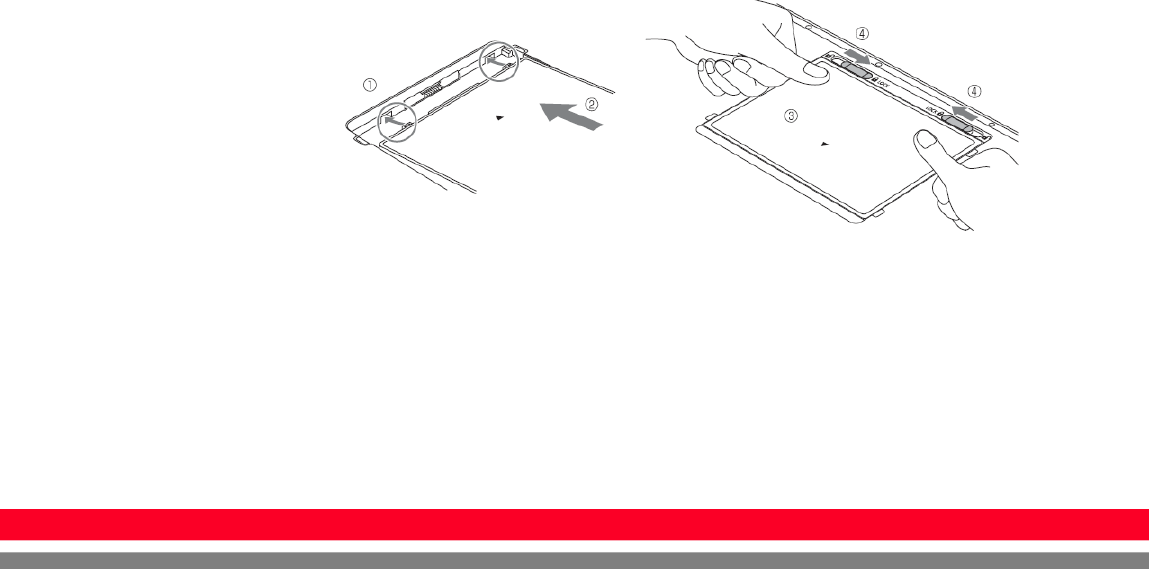
Attach the battery pack. Align the claw on the battery pack and
the groove on the battery bay. Insert the battery pack fully. Push
down the battery pack. Slide the lock lever toward (lock) side and
lock it.
15
R
-
M
-
011
-
121030
Handling
Handle the instrument carefully, as it may be damaged if
something is hit against it, dropped, or receives a strong jolt.
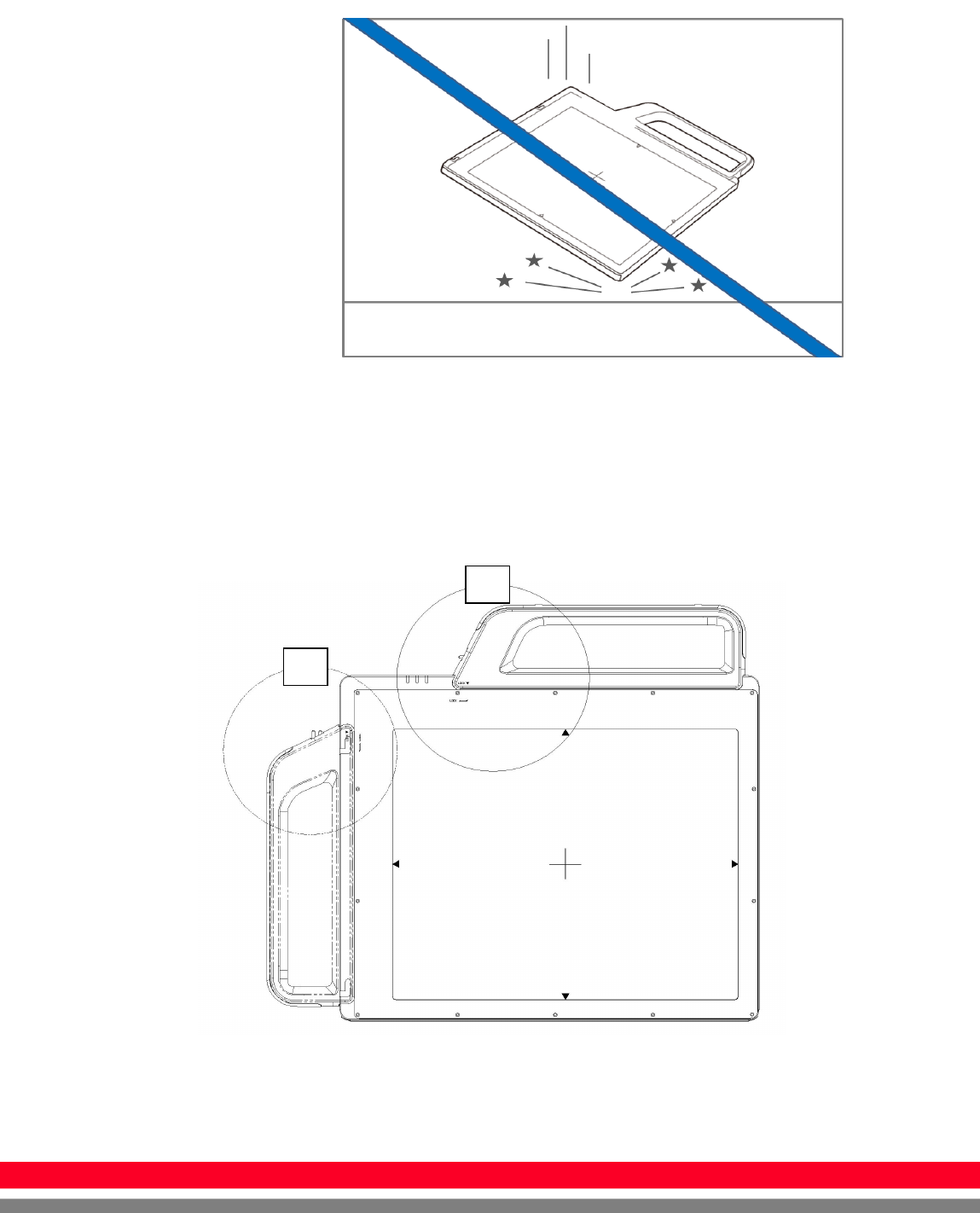
Handle Assembly
※ Insert the handle always in the same direction.
B
A
16
R-M-011-121030
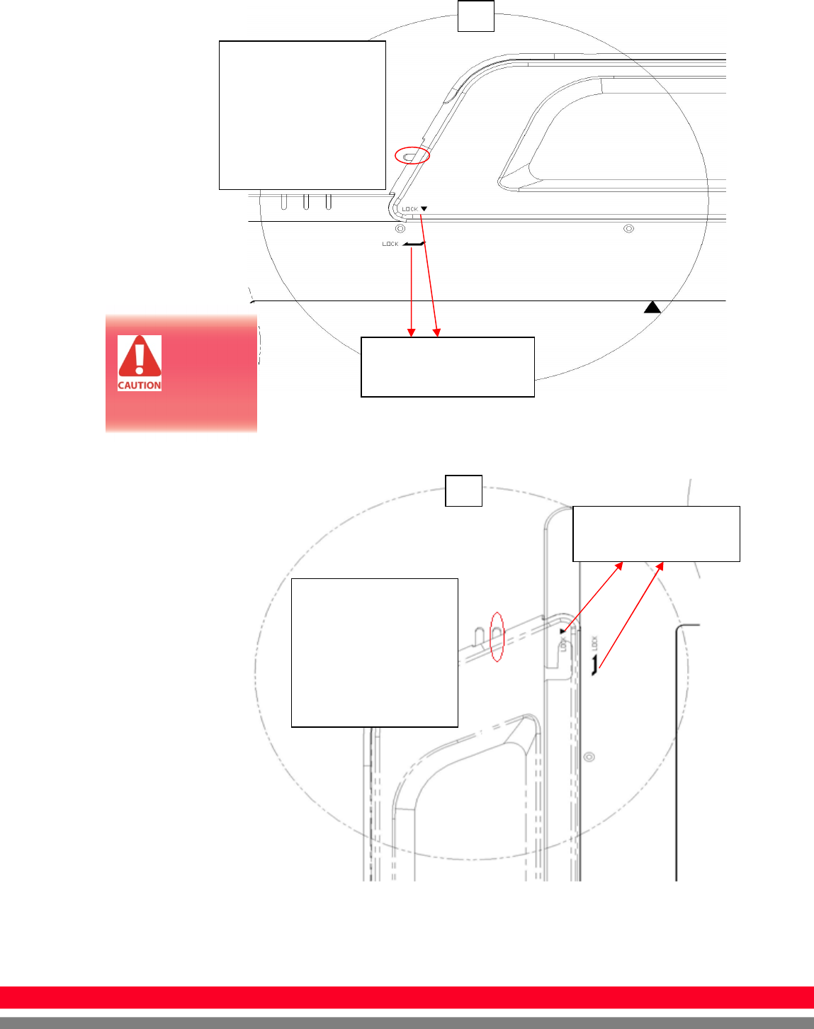
Handle Assembly Type 1
Handle Assembly Type 2
Insert the handle in the
same direction
Insert the handle in
the same direction
A
B
Please confirm lever
position. When the
handle is locked, the
lever should be same
position with the right
picture.
If the
handle is
not locked,
the detector can be
dropped.
Please confirm lever
position. When the
handle is locked, the
lever should be same
position with the right
picture.

17
R
-
M
-
011
-
121030
Before Exposure
Be sure to check the equipment daily and confirm that it works
properly.
Sudden heating of the room in cold areas will cause
condensation to form on the instrument. In this case, wait until
condensation disappears before performing exposure. If the
instrument is used with condensation formed on it, problems may
occur in the quality of the instrument. When an air-conditioner is
going to be used, be sure to raise/lower the temperature
gradually so that a difference in temperature in the room and in
the instrument does not occur, to prevent forming of
condensation.
During Exposure
Do not use the detector near devices generating a strong
magnetic field. Doing so may produce image noise or artifacts.
Do not apply excessive weight to the sensor unit. Otherwise, the
sensor may be damaged.
18
R-M-011-121030
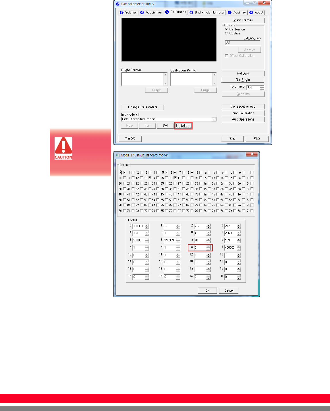
Sleep Mode/Wake up
Control “e” parameter : sleep time
- 0 : disabled (default)
- 1 : 1 sec
- 2 : 2 sec …
- 600 : 600 sec
If you set sleep time, the detector goes to the sleep mode after “N” sec after
acquiring image
If you want to wake up the detector, Press the power button(less than 1 second)
Do not
change
parameters
except “Control e”
19
R
-
M
-
011
-
121030
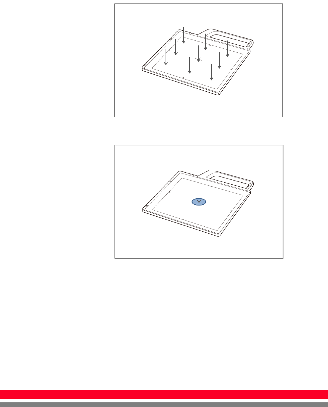
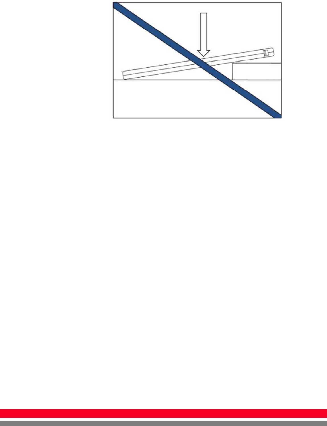
Limit of Load
Uniform load: 150 kg over the whole area of sensor window.
Local load: 100 kg on an area 40 mm in diameter.
20
R-M-011-121030
Be sure to use the sensor unit on a flat place so it will not bend.
Otherwise, the sensor may be damaged.
Disinfection and Cleaning
Do not spray the detector directly with disinfectants or detergents.
Do not use anything other than neutral detergent for cleaning the
cover of the instrument. Otherwise, the coating will be corroded.
Others
Be sure to reconnect the cables to the proper connectors.
Otherwise, the instrument may malfunction or may be damaged.

21
R
-
M
-
011
-
121030
Technical Features
Mechanical Features
Size 395 x 337 x 18 mm
Weight 2.85 kg (incl. Battery pack)
Encapsulation Material
Mg
Window Material Carbon fiber plate with 1.4 mm thickness
Electrical Features
Detector
Sensor Type Amorphous Silicon with TFT (Single Panel)
X-ray Converter CsI:Tl
Total Pixel Number 2080 × 2560 pixels
Active Pixel Area 25.9 cm × 32.0 cm
Active Pixel Number 2040 × 2520 pixels
Pixel Pitch 127 μm
Limiting Resolution Max. 3.9 lp/mm
Energy Range 40 - 150 kV
A/D Conversion 16 bits
Frame Rate 240 fph
Preview Time < 2.0 sec
Charge Integration
Time upto 4 sec
Max. Linear Dose Typ. 60 μGy @ SID 1500 mm
Saturation Dose Typ. 70 μGy @ SID 1500 mm
Data Interface
- Wireless
- Wire
Wi-Fi (802.11a/g/n)
Gigabit Ethernet
Under RQA5 condition (70kVp, 21mmAl)
Preview time may vary by complex factors
22
R-M-011-121030
Battery
Size 232.5 x 132.8 x 7 mm
Weight Typ. 0.3 kg
Input 12.5 VDC
Output 11.1 VDC
Charging time Typ. 2.5 hours
Capacity Typ. 3400 mAh
The number of times
being acquired image 600 images
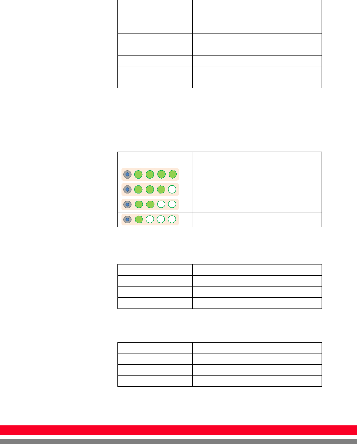
The Battery level can be displayed on the LED status of battery.
If the battery level goes down under 25%, please charge the
battery
Display Battery level
75~100 %
50~75 %
25~50 %
0~25 %
Charger
Size 267.5 x 100 x 77 mm
Weight Typ. 0.86 kg
Input 20 VDC
Output 11.1 VDC
Adapter
Size 160 x 76 x 43.7mm (cable length: 1.28m)
Weight Typ. 0.92 kg
Input 100~240 VAC, 47~63 Hz, 1.4~0.6A
Output 20 VDC, Max 6.0A

23
R
-
M
-
011
-
121030
Wireless Spec
Standard 802.11a/g/n compliance
Peak Rate 300Mbps
Frequency 2.4 GHz / 5 GHz
Bandwidth 20MHz/40MHz
MIMO 2x2
5.15~5.25 GHz band is restricted to indoor operations only. (for FCC)
5.15~5.350 GHz band is restricted to indoor operations only. (for CE)
5.15~5.350 GHz is indoor use only. (for Japan)
※ Recommended Maximum operable distance : 7m
(From the Access Point)

24
R-M-011-121030
Environmental requirement
Item Min. Typ. Max. Unit Note
Temperature -10 50 ℃
Humidity 10 80 %
H.R.
Pressure 70 106 kPa
Shocks
(Wrapping
condition)
10G
(25G)
16ms,
1000times, in
6directions,
non-Driving
Vibrations
(Wrapping
condition)
2G
(10G)
10-150Hz,
10Sweeps,
1min/Octave,
XYZ axis
※ Regularly changed parts : Battery (warranty 6 months)
PC Requirements
Processor : At least Intel Pentium IV HT with 2.8GHz, Intel
Core Duo / Core 2 or comparable AMD Dual Core processor
At least 2 GB RAM
At least 40 GB hard disk for the software, in addition to the
required archive capacity for image storage
Upper that Intel® PRO/100VE Network card
Graphics card/monitor : Resolution of at least 1,280 x 1,024
pixels in True Color mode
OS : Windows XP, vista, 7(32/64 bit)
25
R
-
M
-
011
-
121030
Installation
The Detector is composed of sensitive electronic parts and
components. It is recommended to use the product in a clean
place and to exercise caution to ensure that it is not affected by
dust or liquids. It is recommended to Use a dry and soft cloth to
clean the detector housing.
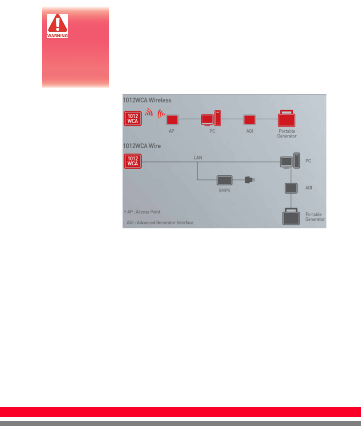
General interface
Connection
Power Connection
A. Connect the battery pack or power cable to the equipment.
B. Connect the USB cable from your PC to AGI.
※ Be sure to sure only the dedicated battery pack, RB37WH
for 1012WCA.
Portable
Imaging
processing
unit must be
installed in a way
that enables the
user to achieve
optimal use

26
R-M-011-121030
Wireless Communication
A. AP Router(Line sharer) setting
- SSID : Griffon
- Internal network
- IP address : 2.2.2.1
- Subnet mask : 255.255.255.0
- Dynamic IP allocation range : 2.2.2.2~2.2.2.254
- Pre-Shared Key(Password) : project302
- Authentication methods : WPAPSK or WPA2PSK
- Password methods : TKIP/AES
- AP IP : 2.2.2.1
- Channel (Frequency)
- Avoid crowded channel
(Using wireless detector under crowded channel result
in low performance)
- If available, Use ‘Auto-Channel Selection’ function
of router to find optimal channel
B. Reception Indicator
Link LED flickering
Blink Speed : Slow – Low link quality
Fast – High link quality
27
R
-
M
-
011
-
121030
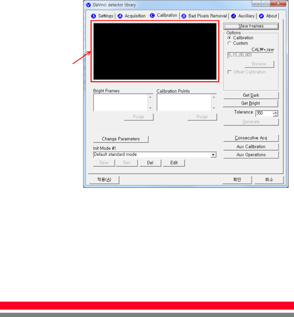
C. Checking Link Quality
- After wireless connection is established, perform ‘Get Bright’
in ‘Calibration’ tap.
- Check the value named ‘Wireless Signal’ in black log screen.
Wireless Signal = Link Quality (Max. 100)
The value ‘Wireless
Signal’ will be
displayed here
28
R-M-011-121030
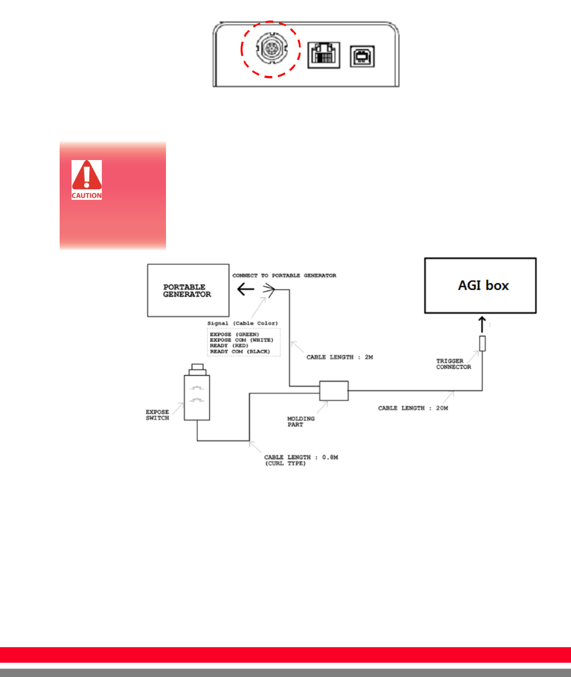
Trigger Connection
A. Connect the P-interface cable to the generator
X-ray Generator Connection
Connect the P-interface cable between the AGI box and X-ray
generator.
A. Wiring Mode 1 : P-interface cable mode
Make
assurance
doubly sure
SIGNAL RATING
before connection.
29
R
-
M
-
011
-
121030
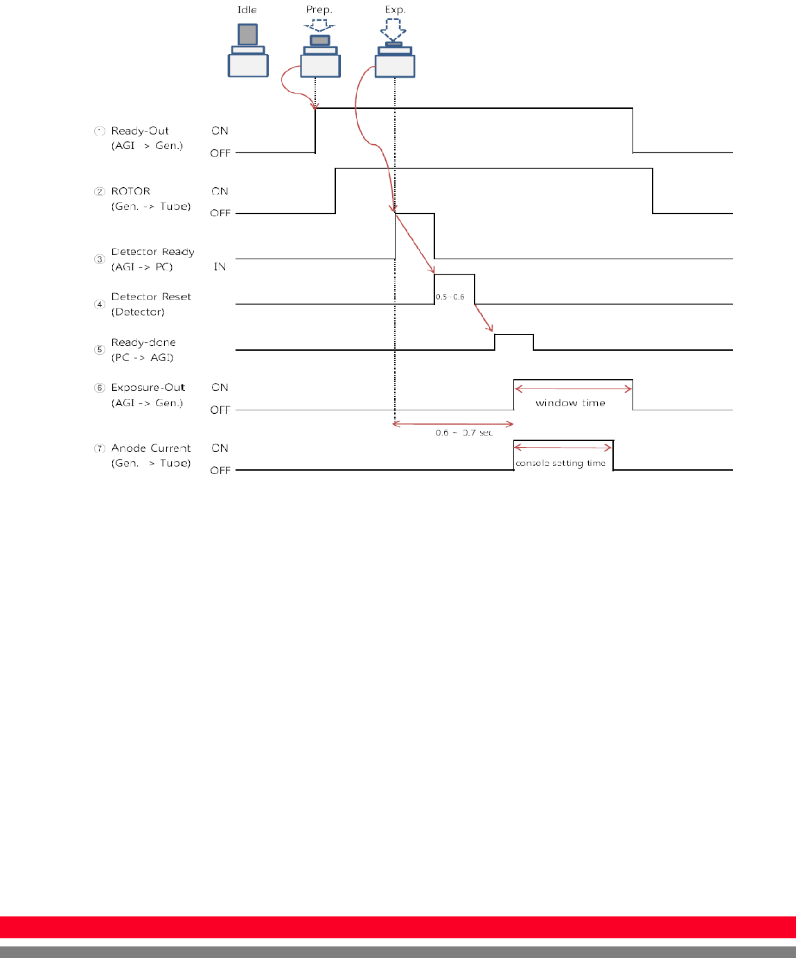
Operating description
The window time can be changed. Refer to the following pictures
30
R-M-011-121030
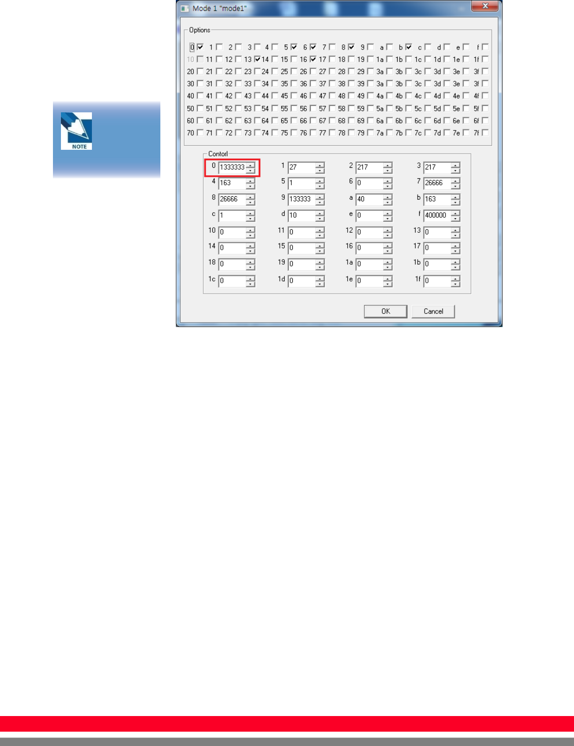
Exposure
Time(*clk)
1333333 is
designate to 0.5sec
31
R
-
M
-
011
-
121030
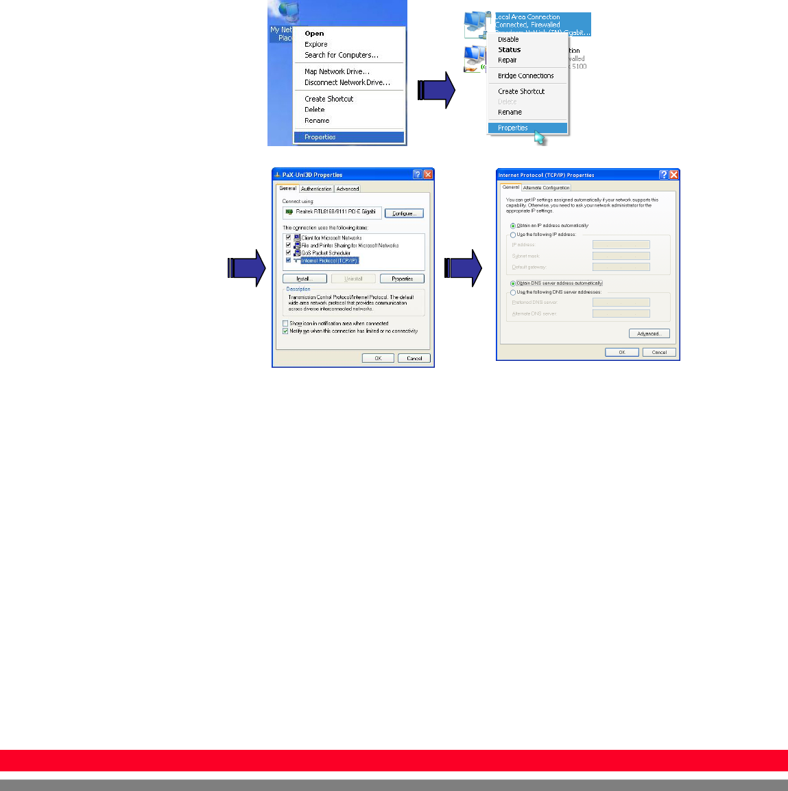
IP set up
[My Network Places] → [Properties] → [Local Area Connection]
→ [Properties] → [Internet Protocol (TCP/IP)]
→ [Use the following IP address]
IP address : Obtain an IP address automatically
IP address :
Obtain an IP address automatically