Rayence RY1417WGB Industrial Image Processing Unit User Manual
Rayence Co., Ltd. Industrial Image Processing Unit
UserManual.wiki
>
Rayence
>
RY1417WGB User Manual
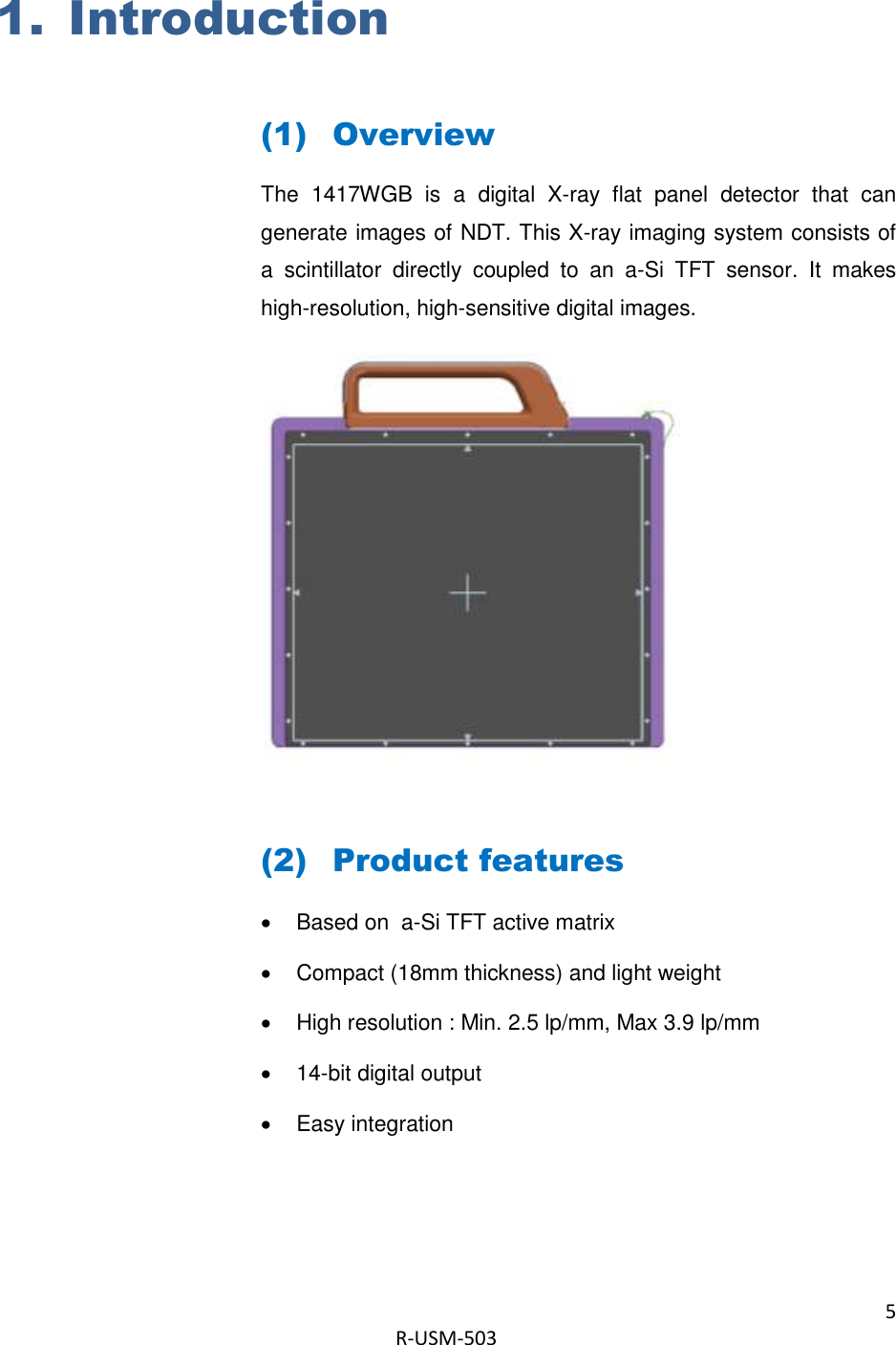
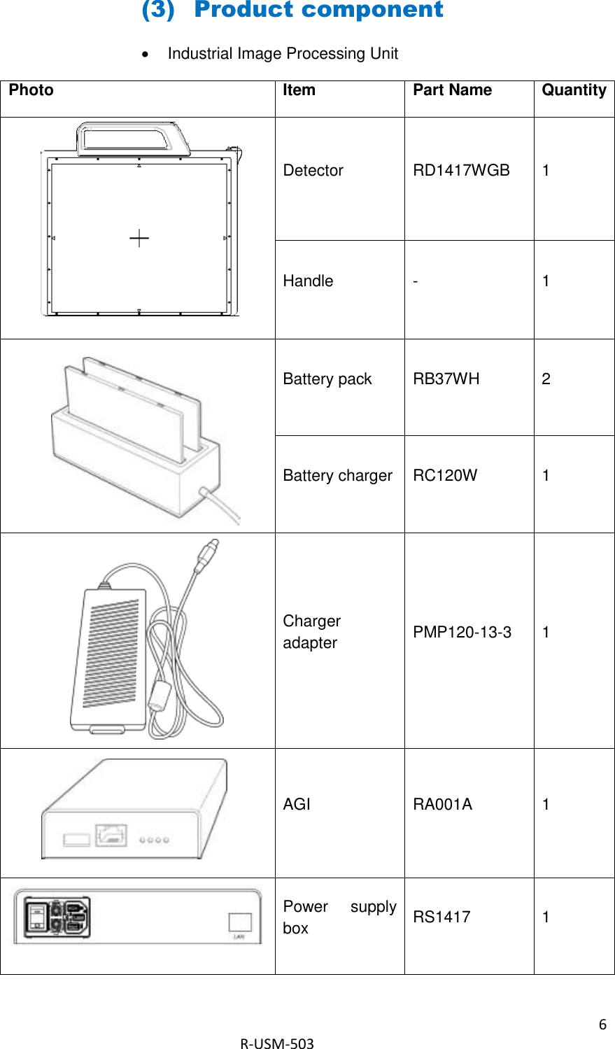
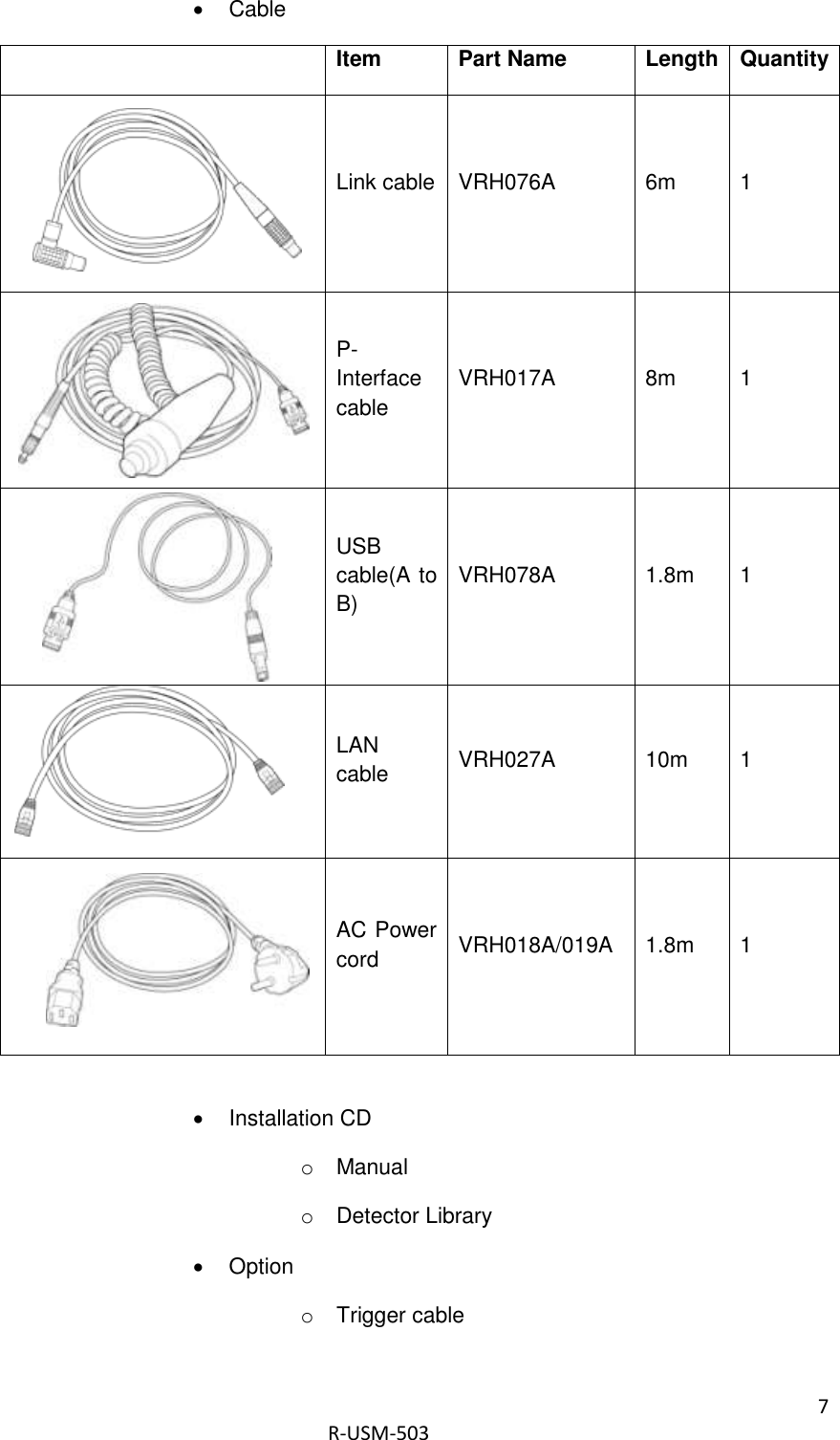
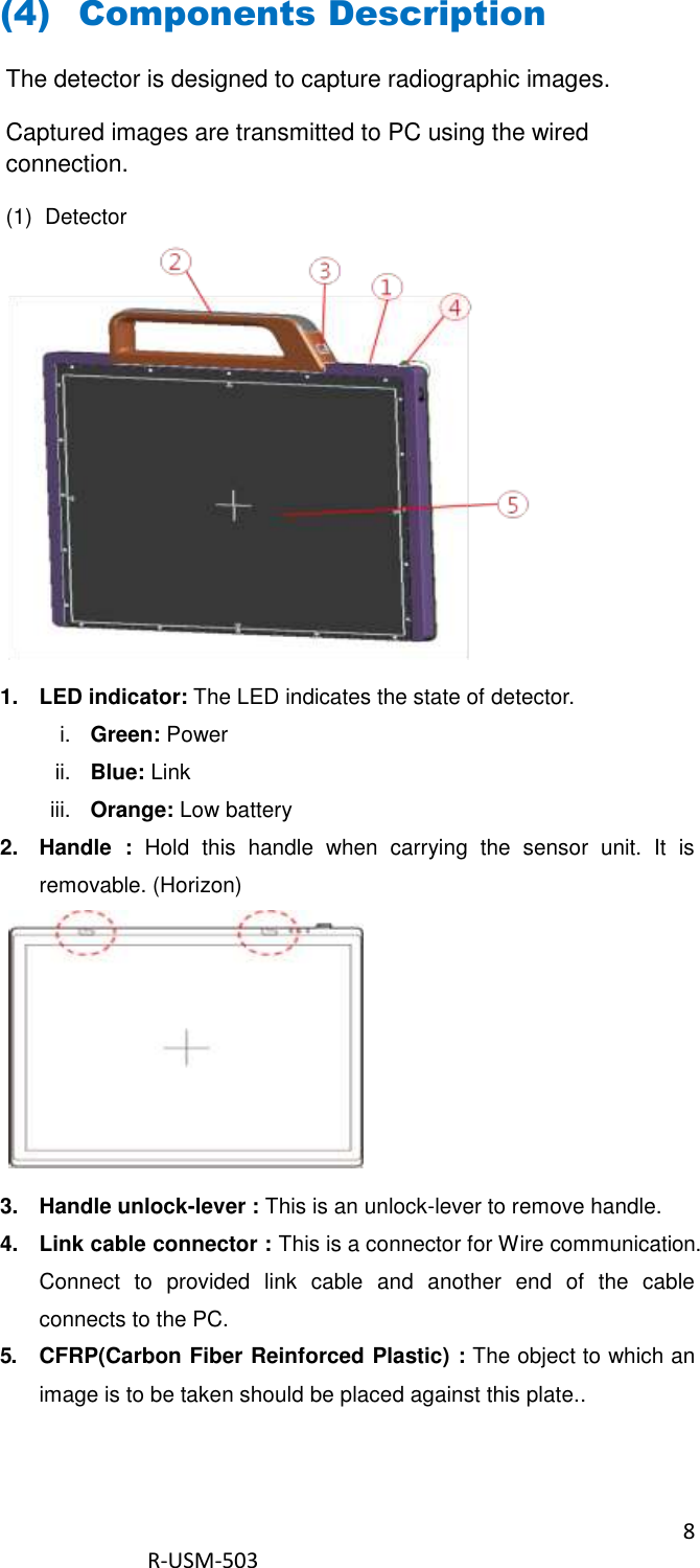
User manual
Navigation menu
Upload a User Manual
Namespaces
Wiki Guide
HTML
PDF
Info
Views
User Manual
Discussion / Help
Navigation

![34 R-USM-503 (4) IP set up [My Network Places] → [Properties] → [Local Area Connection] → [Properties] → [Internet Protocol (TCP/IP)] → [Use the following IP address] IP address: Obtain an IP address automatically (5) Checking Connection Check LED on the detector & power supply Ping test: [Start] →[Run] →ping -t 192.168.1.80 IP address : Obtain an IP address automatically](https://usermanual.wiki/Rayence/RY1417WGB/User-Guide-2231256-Page-34.png)
![35 R-USM-503 (6) Using Web Manager (IP, SSID Change / Upgrade FW) Change IP Address of Detector A. Turn on Detector and connect to PC (wired connection is recommended) B. After detector boot up, Launch web-browser (Optimized for Chrome/Internet Explorer) C. Connect to “http://[Detector’s IP]“ D. Select IP address to change from drop-down menu](https://usermanual.wiki/Rayence/RY1417WGB/User-Guide-2231256-Page-35.png)
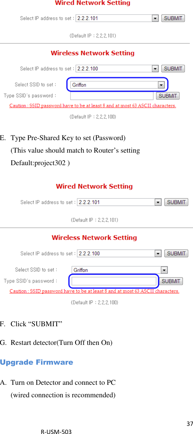
![36 R-USM-503 E. Click “SUBMIT” F. Restart detector(Turn Off then On) Change SSID and PSK(Pre-Shared Key) A. Turn on Detector and connect to PC (wired connection is recommended) B. After detector boot up, Launch web-browser (Optimized for Chrome/Internet Explorer) C. Connect to “http://[Detector’s IP]“ D. Select SSID to set (This value should match to Router’s setting)](https://usermanual.wiki/Rayence/RY1417WGB/User-Guide-2231256-Page-36.png)
![38 R-USM-503 B. After detector boot up, Launch web-browser (Optimized for Chrome/Internet Explorer) C. Connect to “http://[Detector’s IP]“ D. Select firmware file by click “Choose File” button. (Released file is named ‘fw_ppc’) E. Click ‘Upload File’ button F. Click ‘Flash Write’ button G. Restart detector(Turn Off then On)](https://usermanual.wiki/Rayence/RY1417WGB/User-Guide-2231256-Page-38.png)
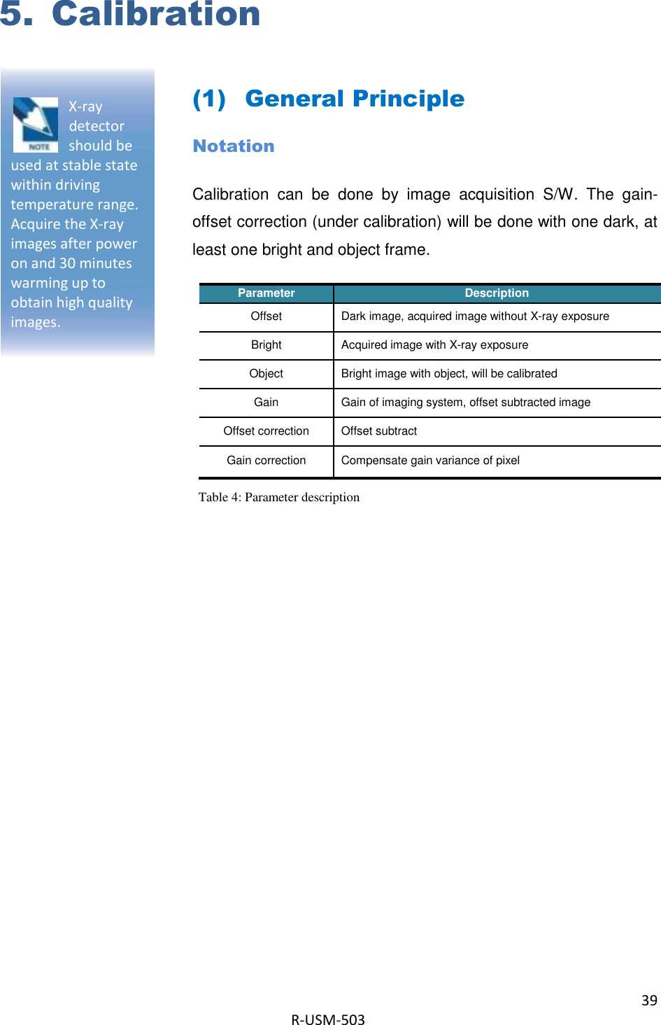
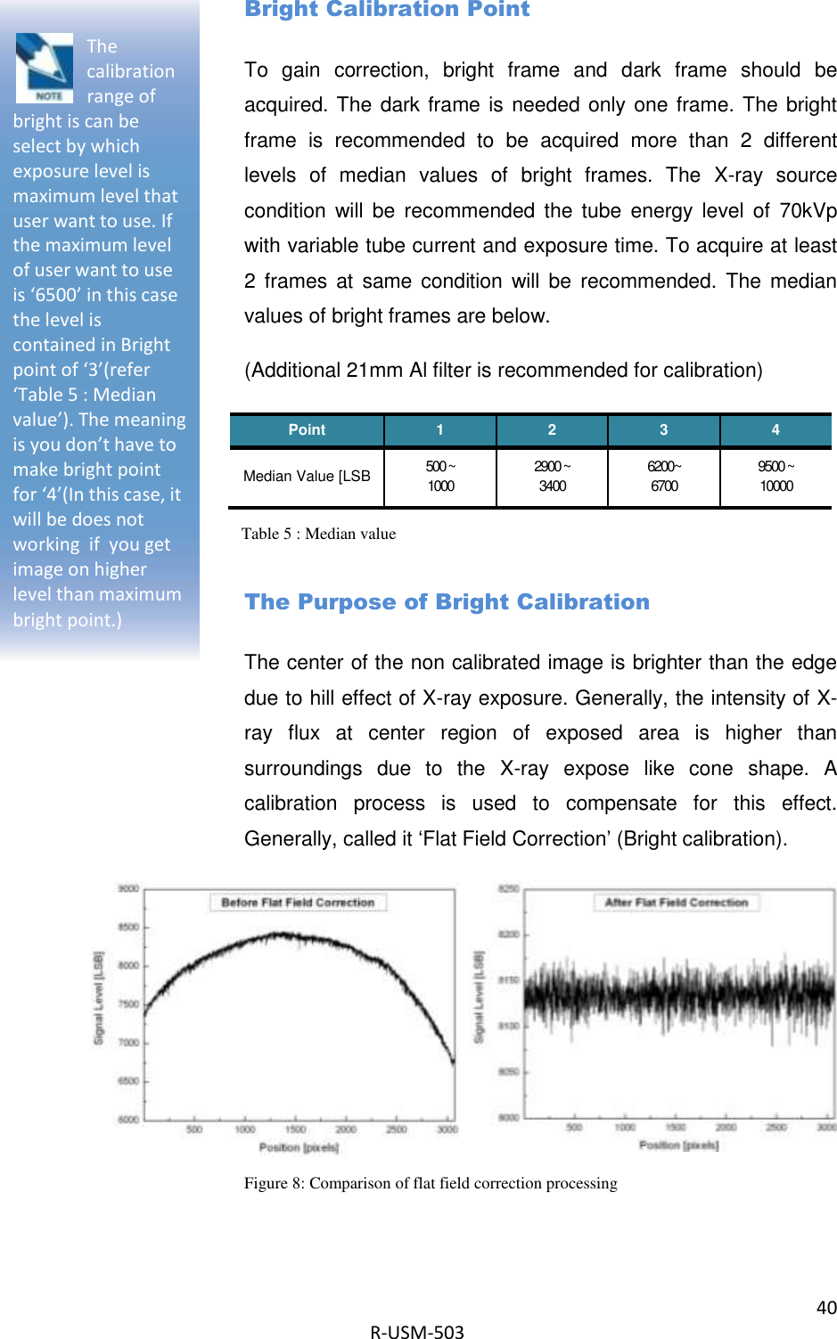
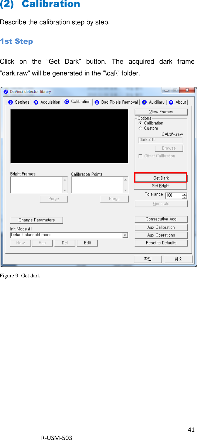
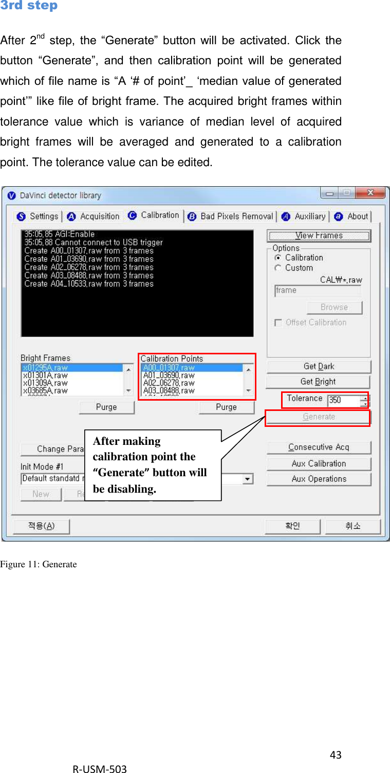
![42 R-USM-503 2nd Step Push “Get Bright” button at different four of X-ray condition. The X-ray condition should be set or tested before, same as the level of ‘1.2’. Push “Get Bright” button at least 2 times at same condition, and then the offset subtracted bright (gain) is generated which of filename is “xNNNNNA.raw(Refer to NOTE) Figure 10: Get bright. Click button [Get Bright]. It will produce frame with name %CAL% xNNNNNA.raw, where NNNNN is median pixel’s value within current image borders after offset calibration (cut frame edges are never used during calibration). Suffix ‘A’ (it also could be ‘B’,’C’ etc) avoids casual coincidence of file names.](https://usermanual.wiki/Rayence/RY1417WGB/User-Guide-2231256-Page-42.png)
![49 R-USM-503 Histogram’s presentation Relative Histogram Scale [H]=1000 means that that the distance depicted as “H” on the drawing matches 1% of total number of pixels. Respectively [H]=100 means that “H” matches 0.1% of pixels and [H]=500 means that “H” matches 0.5% of pixels. Figure 17: Description of histogram](https://usermanual.wiki/Rayence/RY1417WGB/User-Guide-2231256-Page-49.png)
![61 R-USM-503 Appendix Dimension [unit : mm]](https://usermanual.wiki/Rayence/RY1417WGB/User-Guide-2231256-Page-61.png)