Rayence RYRAP001A Interface Box User Manual
Rayence Co., Ltd. Interface Box
UserManual.wiki
>
Rayence
>
RYRAP001A User Manual
User Manual
Navigation menu
Upload a User Manual
Namespaces
Wiki Guide
HTML
PDF
Info
Views
User Manual
Discussion / Help
Navigation
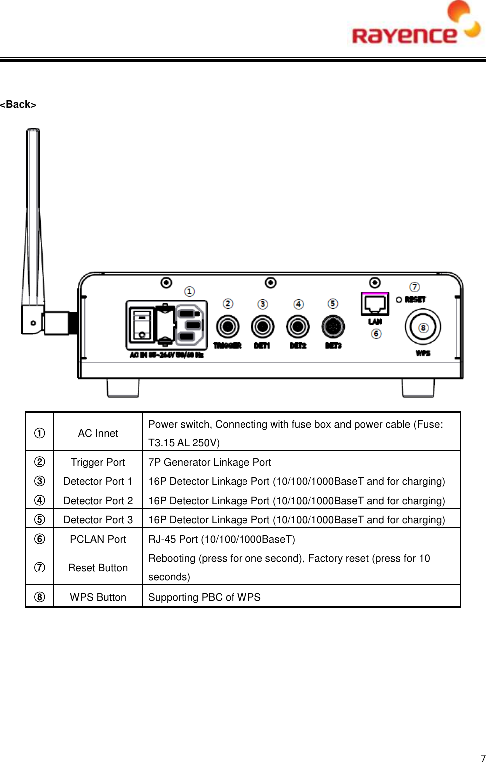


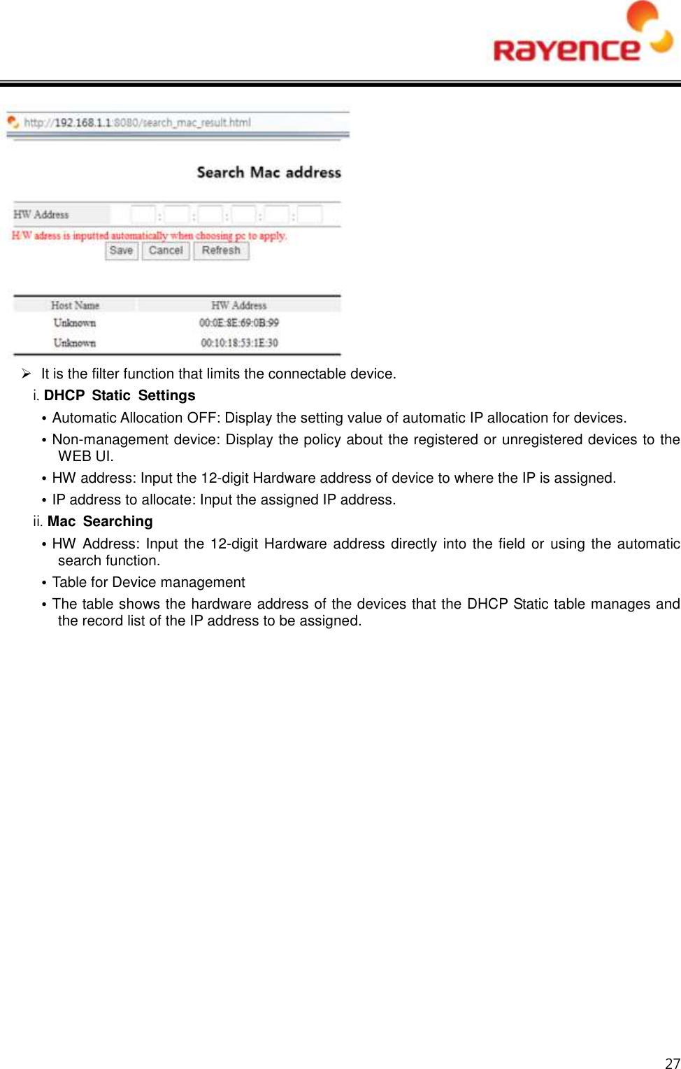
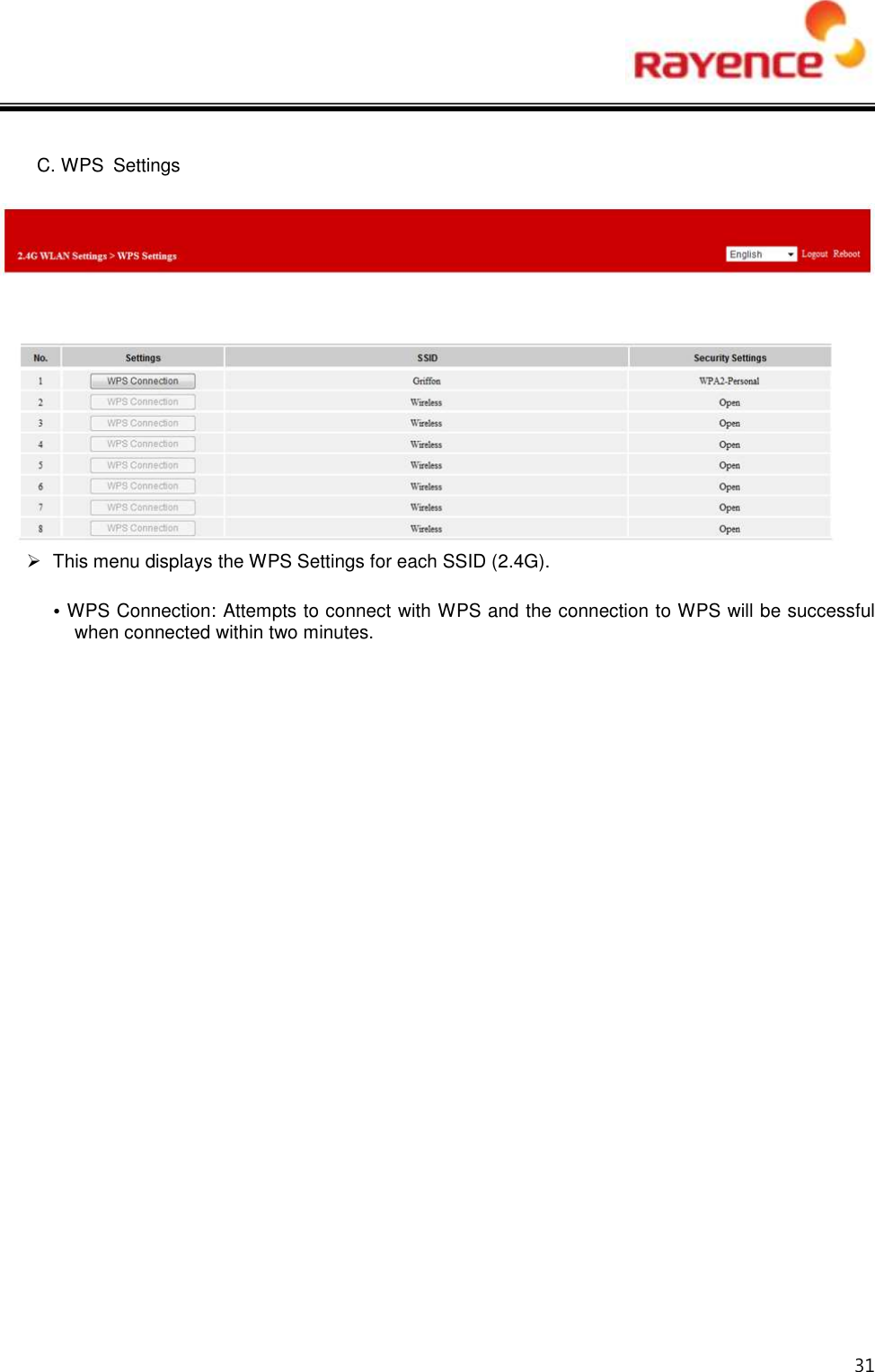
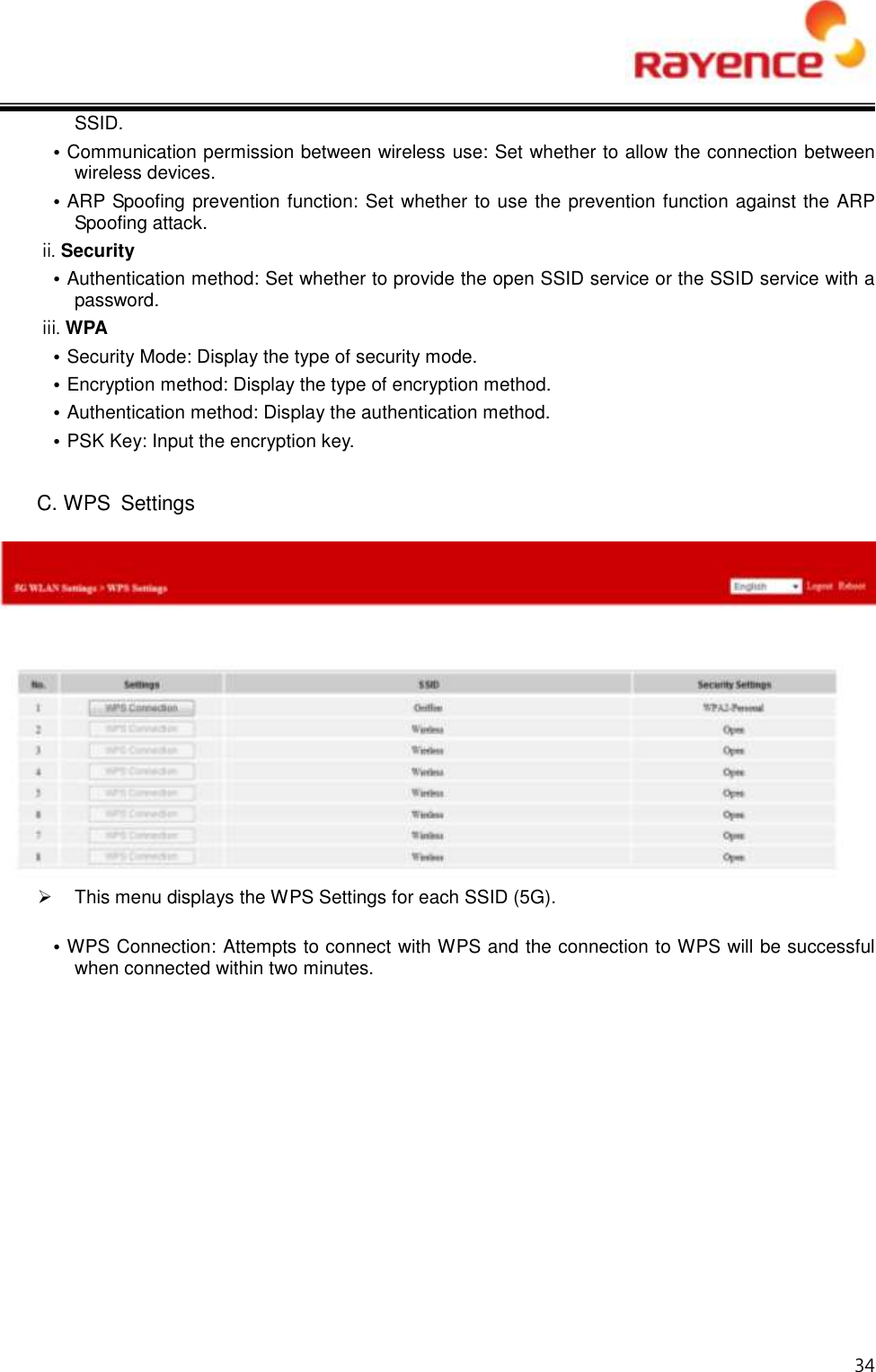
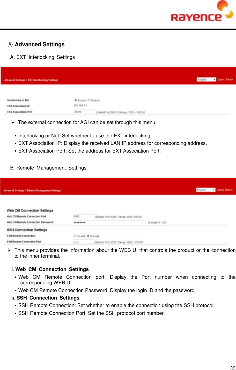
![36 C. Firmware Upgrade The firmware of the product can be upgraded. • Firmware File Selection: Search the Firmware binary inside the locally connected terminal. • Upgrade Start: Select the normal Firmware binary and click the [Upgrade Start] button. D. Configuration Clear • Reset the settings value. At this time, the parameter set by users may be initialized.](https://usermanual.wiki/Rayence/RYRAP001A/User-Guide-3040452-Page-37.png)