Rayson Technology BTM-22X Bluetooth Module User Manual BTM222 DataSheet
Rayson Technology Co., Ltd. Bluetooth Module BTM222 DataSheet
Manual

Rayson
Bluetooth
®
Module
Class1 BC04-ext Module BTM-222
Features Outline
Block Diagram
■ Bluetooth Ver. 2.0+EDR certification
■ Transmit Power up to +18dBm(class1)
■ Low current consumption:
Hold, Sniff, Park, Deep sleep mode
■ 3.0V to 3.6V operation
■ Full Bluetooth Data rate over UART and USB
■ Support up to 7 ACL links and 3 SCO links
■ Enhanced Data Rate(EDR) compliant
for both 2Mbps and 3Mbps modulation modes
■ Interface: USB, UART&PCM( for voice codec)
■ SPP firmware with AT commands
■ RoHS Compliant
■ Small outline: 28.2 X 15.0 X 2.8 mm
Application
● Access point
● Domestics and Industrial applications
● Serial Adapter
● GPS, POS, Barcode Reader

Electrical Characteristics
Absolute Maximum Ratings
Parameter Min. Max. Unit
Storage Temperature -40 +85 ℃
℃℃
℃
Supply Voltage(VDD) 2.7 3.7 DCV
Supply Voltage(PVCC) 3.0 3.6 DCV
Other Pin Voltage Vss-0.4 VDD+0.4 DCV
Recommended Operating Conditions
Parameter Min. Typ. Unit
Temperature -20 +75 ℃
℃℃
℃
Supply Voltage(VDD) 3.0 3.3 DCV
Supply Voltage(PVCC) 3.0 3.3 DCV
General Electrical Specification
Parameter Description Min. Typ. Max. Unit
Carrier Frequency 2.402 2.480 GHz
RF Output Power Measured in 50ohm 15 16.5 18 dBm
RX sensitivity - -88 -86 dBm
Load Impedance No abnormal Oscillation 5:1
Input Low Voltage RESET,UART,GPIO,PCM
-0.30 - 0.80 DCV
Input High Voltage RESET,UART,GPIO,PCM
0.7VDD
- VDD+0.3
DCV
Output Low Voltage UART,GPIO,PCM - - 0.40 DCV
Output High Voltage UART,GPIO,PCM VDD-0.4
- - DCV
Average Current Consumption
Receive DM1 114 mA
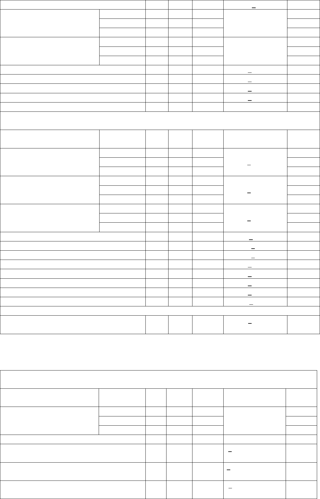
Radio Characteristics - Basic Data Rate
Transmitter , VDD = 3.3V Temperature =+20°C
Frequency
(GHz)
Min. Typ.
Max. Bluetooth
Specification
Unit
2.402 16 17.5 18.5 dBm
2.441 16 17.5 18.5 dBm
RF transmit power
2.480 16 17.5 18.5
-6 to +20
dBm
2.402 - 12 25 kHz
2.441 - 10 25 kHz
Initial carrier frequency tolerance
2.480 - 9 25
±75
kHz
2.402 - 890 1000 kHz
2.441 - 870 1000 kHz
-20dB bandwidth for modulated
carrier
2.480 - 820 1000
< 1000
kHz
2.402 - ±10 ±20 kHz
2.441 - ±10 ±20 kHz
Carrier Frequency Drift (single
slot packet DH1)
2.480 - ±10 ±20
<25
kHz
2.402 - ±10 ±20 kHz
2.441 - ±10 ±20 kHz
Carrier Frequency Drift (five slot
packet DH5)
2.480 - ±10 ±20
<40
kHz
2.402 - ±7 ±14 kHz/50µs
2.441 - ±7 ±14 kHz/50µs
Drift Rate
2.480 - ±7 ±14
<20
kHz/50µs
RF power control range 16 25 - >16 dB
2.402 145 165 170 kHz
2.441 145 165 170 kHz
△f1
avg
“Maximum Modulation”
2.480 145 165 170
140<△f1
avg
<175
kHz
2.402 115 150 - kHz
2.441 115 150 - kHz
△f2
maz
“Minimum Modulation”
2.480 115 150 -
>115
kHz
Adjacent channel transmit power F=F
0
±2MHz
- -35 -20 < - 20 dBm
Adjacent channel transmit power F=F
0
±3MHz
- -45 -40 < - 40 dBm
Adjacent channel transmit power F>F
0
+3MHz
- -50 -40 < - 40 dBm
Adjacent channel transmit power F<F
0
-3MHz
- -50 -40 < - 40 dBm
Receiver , VDD = 3.3V Temperature =+20°C
Frequency
(GHz)
Min. Typ.
Max. Bluetooth
Specification
Unit
2.402 - -88 -86 dBm
2.441 - -88 -86 dBm
Sensitivity at 0.1% BER
(Single slot packets) 2.480 - -88 -86
< - 70
dBm
2.402 - -88 -86 dBm
2.441 - -88 -86 dBm
Sensitivity at 0.1% BER
(Multi slot packets) 2.480 - -88 -86
< - 70
dBm
2.402 -20 -10 - dBm
2.441 -20 -10 - dBm
Maximum received signal level at
0.1% BER
2.480 -20 -10 -
> - 20
dBm
C/I co-channel - 6 11 < 11 dB
Adjacent channel selectivity C/I F=F
0
+1 MHz - -4 - < 0 dB
Adjacent channel selectivity C/I F=F
0
- 1MHz - -4 - < 0 dB
Adjacent channel selectivity C/I F=F
0
+2 MHz - -38 - < - 30 dB
Adjacent channel selectivity C/I F=F
0
- 2MHz - -23 - < - 20 dB
Adjacent channel selectivity C/I F>=F
0
+3 MHz - -45 - < - 40 dB
Adjacent channel selectivity C/I F<=F
0
-5 MHz - -44 - < - 40 dB
Adjacent channel selectivity C/I F=F
image
- -22 - < - 9 dB
F
0
= 2441 MHz
Maximum level of intermodulation interference
(n=5)
-30 > -39 dBm
Radio Characteristics – Enhanced Data Rate
Transmitter , VDD = 3.3V Temperature =+20°C
Frequency
(GHz)
Min.
Typ. Max. Bluetooth
Specification
Unit
2.402 - 16 - dBm
2.441 - 16 - dBm
Maximum RF transmit power
(note)
2.480 - 17 -
-6 to +20
dBm
Relative transmit power - -1.6 - -4 to +1 dB
π/4 DQPSK
Maximum carrier frequency stability w
0
- 2 - < ±10 for all blocks
kHz
π/4 DQPSK
Maximum carrier frequency stability w
i
- 6 - < ±75 for all packets
kHz
π/4 DQPSK
Maximum carrier frequency stability | w
0
+ w
i
|
- 8 - < ±75 for all blocks
kHz

8 DPSK
Maximum carrier frequency stability w
0
- 2 - < ±10 for all blocks
kHz
8 DPSK
Maximum carrier frequency stability w
i
- 6 - < ±75 for all packets
kHz
8 DPSK
Maximum carrier frequency stability | w
0
+ w
i
|
- 8 - < ±75 for all blocks
kHz
RMS DVEM - 7 - < 20 %
99% DEVM - 13 - < 30 %
π/4 DQPSK
Modulation Accuracy
Peak DEVM - 19 - < 35 %
RMS DVEM - 7 - < 13 %
99% DEVM - 13 - < 20 %
8 DPSK
Modulation Accuracy
Peak DEVM - 17 - < 25 %
F>F
0
+3 MHz - <-50 - < -40 dBm
F<F
0
-3 MHz - <-50 - < -40 dBm
F=F
0
-3 MHz - -46 - < -40 dBm
F=F
0
-2 MHz - -34 - < -20 dBm
F=F
0
-1 MHz - -35 - < -26 dBm
F=F
0
+1 MHz - -35 - < -26 dBm
F=F
0
+2 MHz - -31 - < -20 dBm
In-band spurious emissions
F=F
0
+3 MHz - -33 - < -40 dBm
EDR Differential Phase Encoding No
Errors
> 99 %
Receiver , VDD = 3.3V Temperature =+20°C
Modulation Min.
Typ. Max. Bluetooth
Specification
Unit
π/4 DQPSK - -87 - < -70 dBm Sensitivity at 0.1% BER
8 DPSK - -78 - < -70 dBm
π/4 DQPSK - -8 - > -20 dBm Maximum received signal level at
0.1% BER 8 DPSK - -10 - > -20 dBm
π/4 DQPSK - 10 - < +13 dB C/I co-channel at 0.1% BER
8 DPSK - 19 - < +21 dB
π/4 DQPSK - -10 - < 0 dB Adjacent channel selectivity C/I
F=F
0
+1 MHz 8 DPSK - -5 - < +5 dB
π/4 DQPSK - -11 - < 0 dB Adjacent channel selectivity C/I
F=F
0
-1 MHz 8 DPSK - -5 - < +5 dB
π/4 DQPSK - -40 - < -30 dB Adjacent channel selectivity C/I
F=F
0
+2 MHz 8 DPSK - -40 - < -25 dB
π/4 DQPSK - -23 - < -20 dB Adjacent channel selectivity C/I
F=F
0
-2 MHz 8 DPSK - -20 - < -13 dB
π/4 DQPSK - -45 - < -40 dB Adjacent channel selectivity C/I
F=F
0
+3 MHz 8 DPSK - -45 - < -33 dB
π/4 DQPSK - -45 - < -40 dB Adjacent channel selectivity C/I
F=F
0
-5 MHz 8 DPSK - -45 - < -33 dB
F
0
= 2405, 2441, 2477 MHz
π/4 DQPSK -20 < -7 dB Adjacent channel selectivity C/I
F=F
image
8 DPSK -15 < 0 dB
Note :
Measurement made using a POWER_TABLE entery of TX_PRE 80, INT PA63, EXT PA255. This ensures that the
Bluetooth requirements for ACP and those defined by the FCC and ETSI are satisfied over the operating
temperature rang of -5℃
℃℃
℃to
+45℃
℃℃
℃. Although the design is capable of generating in excess of +18dBm, regulatory
compliance over the full temperature range of -5℃
℃℃
℃ to +45℃
℃℃
℃ will not be satisfied if the transmit power
approaches this value.

Application Schematic
Title
Size Document Number Rev
Date: Sheet of
<Doc> <Rev Code>
<Title>
A
1 1Thursday , June 24, 2010
TP6
TP5
C69
0.22uF
L7
TP7
R69
100K
C70
2.2uF
C71
CAP NP
L8
INDUCTOR
C72
CAP NP
R70
27
C73
2.2uF
R71 27
SW5
12
E3
ANTENNA
1
TP8
R72
330
J2
USB JACK
VCC 1
D- 2
D+ 3
GND 4
U2
XC6209
VOUT 5
NC 4
GND
2
VIN
1
CE
3
D16
Blue LED / AP2012PBC
3.3V
3.3V
3.3V
3.3V
TX
RX
Link
ANTENNA
matching
circuit
TO Host
R73
330
D17
LED
R74
330
D18
LED
Data
C74
0.1u
U1
BTM-222
GND
1
+V_PA
2
RESET
16
SPIMISO
34
SPIMOSI
31
SPICSB
32
SPICLK
33
UART_CTS
30
UART_TX
27
UART_RTS
28
UART_RX
26
AIO0
3USBDN 21
USBDP 20
PCM_IN 23
PCM_CLK 25
PCM_OUT 24
PCM_SYNC 22
AIO1
4
3V3
17
GND
19
PIO2 7
PIO3 8
PIO4 9
PIO5 11
PIO6 12
PIO7 13
PIO8 14
PIO1 6
PIO0 5
PIO10 36
PIO9 15
RFIO 37
GND 38
GND
29
PIO11 35
GND
39
GND
40
GND
10
GND
18
SPP AT Command sets
+++
(Escape
Sequence)
When the device is in Data mode, it can be forced back into Command mode while
maintaining the connection to the remote device. The sequence characters should be
with 1000ms guard time
When it’s in master mode. This command establish a connection. When it’s in slave
mode, the command will be rejected.
Modifiers Description
A Connect to a device which has been assigned by “ATD= xxxxxxxxxxxx”
A
(
Establish a
connection)
A1~A8 Connect to a device1~8 in neighborhood found through “ATF?”.
This command display the local device BD address
Modifiers Description
B
(Display local
BD address) B? Inquire the Local BD address
This command enable or disable flow control signals (CTS/RTS) of the COM port. Note,
the setting is not affected by ATZ0 but will cause a reboot
Modifiers Description
C
(Flow
Control) C0 Disable flow control.

C1
(Default) Enable flow control.
C? Inquire the current setting
For security purpose, We can specifies the unique remote device can be connected. In
master role, it automatically inquire and search the slave even the slave is
undiscoverable. In slave role, the command should be as a filter condition to accept the
master’s inquiry.
Modifiers Description
D=xxxxxxxx "xxxxxxxx" is a string of 12 hexadecimal digits.
D0
(Default)
Clear Remote BD address setting, inquire any slave in master mode or
accept any master in slave mode.
D
(Set Remote
BD address)
D? Inquire the Remote BD address setting
This command specifies whether the device should echo characters received from the
UART back to the Host
Modifiers Description
E0 Characters received from the UART are not echoed back to the Host
E1
(Default) Characters received from the UART are echoed back to the Host.
E
(Local Echo)
E? Inquire the current setting
This command is used to find any bluetooth device in neighborhood within 60 seconds
timeout. If any device is found, its name and address will be listed. The search ends
with a message “Inquiry ends, xx device(s) found.”
This command is available only when the adaptor is in the manual master role. An AT
can cancel the Inquiry.
Modifiers Description
F
(Find Bluetooth
device)
F? Inquire scan max. 8 Bluetooth neighborhood devices.
This command is used to drop connection either master or slave role. And it is used to
specifiy whether the device could be discovered by remote master device.
note : it will cause a reboot when ATH0 or ATH1 take the effect
Modifiers Description
H Drop current connection in Online command mode
H0 The device enters undiscoverable mode. If a pair have been made, the
original connection could be connected again. Other remote master
device can not discovery this device.
H1
(Default) The device enters discoverable mode.
H
(Discoverable
Control)
H? Inquire the current setting
This command is used to Inquiry the information
Modifiers Description
I0 Inquire the version Codes
I1 Listing all setting value
I
(Information)
I2 Inquire RSSI in Online command mode
This command is used to specify one or two stop bits of COM port
Modifiers Description
K0
(Default) One Stop bit
K
(Stop bits
setting)
K1 Two stop bits

K? Inquire the current setting
This command is used to specify the baud rate of COM port
Modifiers Description
L* 1200bps
L# 2400bps
L0 4800bps
L1 9600bps
L2
(Default) 19200bps
L3 38400bps
L4 57600bps
L5 115200bps
L6 230.4Kbps
L7 460.8Kbps
L8 921.6Kbps
L
(Baud Rate
Control)
L? Inquire the current setting
This command is used to specify the parity bit setting of COM port
Modifiers Description
M0
(Default) None Parity bit.
M1 Odd parity setting.
M2 Even parity setting
M
(Parity bits
setting)
M? Inquire the current setting
We can specifies the device a friendly name using 0 to 9, A to Z, a to z, space and –,
which are all valid characters. Note that "firs space or -, last space or – isn’t permitted".
The default name is “Serial Adaptor”
Modifiers Description
N=xxxxx "xxxxx" is a character string, maxima length is 16
N
(Set
device
name)
N? Inquire the device name
This command is used to enable/disable auto-connection feature in master role. By the
way, it is used to online switch from command mode to data mode.
Note, it will cause a reboot when ATO0 or ATO1 take effect.
Modifiers Description
O Online switch from command mode to data mode
O0
(Default)
Automatically connectting to a device which is assigned in “ATD” or any
available device if “ATD” was not assigned.
O1 Disable auto-connection feature, user should manually use “ATA”
command to connect a remote device.
O
(Auto connect
setting)
O? Inquire the current setting
This command specifies the PIN number. It control to off the PIN code authorization
that allow to establish a connection without PIN code.
Default PIN number is "1234"
Modifiers Description
P
(Set PIN code)
P=xxxx
(Default) "xxxx" is 4~8 digit string

P0 Turn off the PIN code authorization
P? Inquire the current PIN number
The command is used to determine if result Codes should be sent to the Host. When
result Codes are supressed, the device does not generate any characters in response
to the completion of a command or when an event occurs.
Four Result Codes : OK,CONNECT,DISCONNECT,ERROR
Modifiers Description
Q0
(Default) The device will prompt Result Codes
Q1 The device will not prompt Result Codes
Q
(Result
Code
Supression)
Q? Inquire the current setting
This command specifies whether the device could be master or slave device. If change
the role, the adaptor will reboot and clear all paired addresses.
Modifiers Description
R0 The device as master role.
R1
(Default) The device as slave role.
R
(Set Role)
R? Inquire the current setting
This command is used to disable/enable escape sequence “+++”.
Modifiers Description
X0 Disable escape character check.
X1
(Default) Enable escape character check.
X
(Escape
Control)
X? Inquire the current setting
This command is used to restore default setting and reboot
Modifiers Description
Z
(Restore)
Z0 Restore the default setting
The factory settings of UART are as follows:
Baud rate: 19200 bps
Data bit: 8
Parity: none
Stop bit: 1
Flow control: H/W or none

BTM-222 Pin Function
Pin
No.
Pin Name Pin Type Description
1 GND GND Common ground
2 PVCC Power Power Amp. Power Supply(3.3V)
3 AIO(0) Bi-directional
Programmable I/O terminal
4 AIO(1) Bi-directional
Programmable I/O terminal
5 PIO(0) Bi-directional
Programmable I/O terminal
6 PIO(1) Bi-directional
Programmable I/O terminal
7 PIO(2) Bi-directional
Programmable I/O terminal
8 PIO(3) Bi-directional
Programmable I/O terminal
9 PIO(4) Bi-directional
Programmable I/O terminal, (Button Input, active high)
To press the button caused disconnection or reconnection. To
double click the button caused clear all original link records
then repairing. When user press the button more than 3
seconds, then it will restore the default RS232 setting
10 GND GND Common ground
11 PIO(5) Bi-directional
Programmable I/O terminal, (Drive Data status led, active high, it will
flash 3 times when it reboot).
12 PIO(6) Bi-directional
Programmable I/O terminal, (RFCOMM connection status).
13 PIO(7) Bi-directional
Programmable I/O terminal, (Drive Link status led, active high, it will
flash 3 times when it reboot).
14 PIO(8) Bi-directional
Programmable I/O terminal, (Drive Power status led, active high, it
will flash 3 times when it reboot).
15 PIO(9) Bi-directional
Programmable I/O terminal, (Drive RS232 force on, active high).
16 RESETB CMOS input Reset input of module, Active low
17 VCC Power 3.3V power supply input
18 GND GND Common ground
19 GND GND Common ground
20 USB_DP Bi-directional
USB data plus
21 USB_DN Bi-directional
USB data minus
22 PCM_SYNC
Bi-directional
Synchronous data sync
23 PCM_IN CMOS input Synchronous data input
24 PCM_OUT CMOS output
Synchronous data output
25 PCM_CLK Bi-directional
Synchronous data clock
26 UART_RX CMOS input UART data input
27 UART_TX CMOS output
UART data output
28 UART_RTS
CMOS output
UART request to send(active low)
29 GND GND Common ground
30 UART_CTS
CMOS input UART clear to send(active low)
31 SPI_MOSI CMOS input Serial Peripheral Interface data input
32 SPI_CSB CMOS input Chip select for Synchronous Serial Interface(active low)
33 SPI_CLK CMOS input Serial Peripheral Interface clock
34 SPI_MISO CMOS output
Serial Peripheral Interface data output
35 PIO(11) Bi-directional
Programmable I/O terminal
36 PIO(10) Bi-directional
Programmable I/O terminal
37 RF_IO Analogue Antenna interface
38 GND GND Common ground
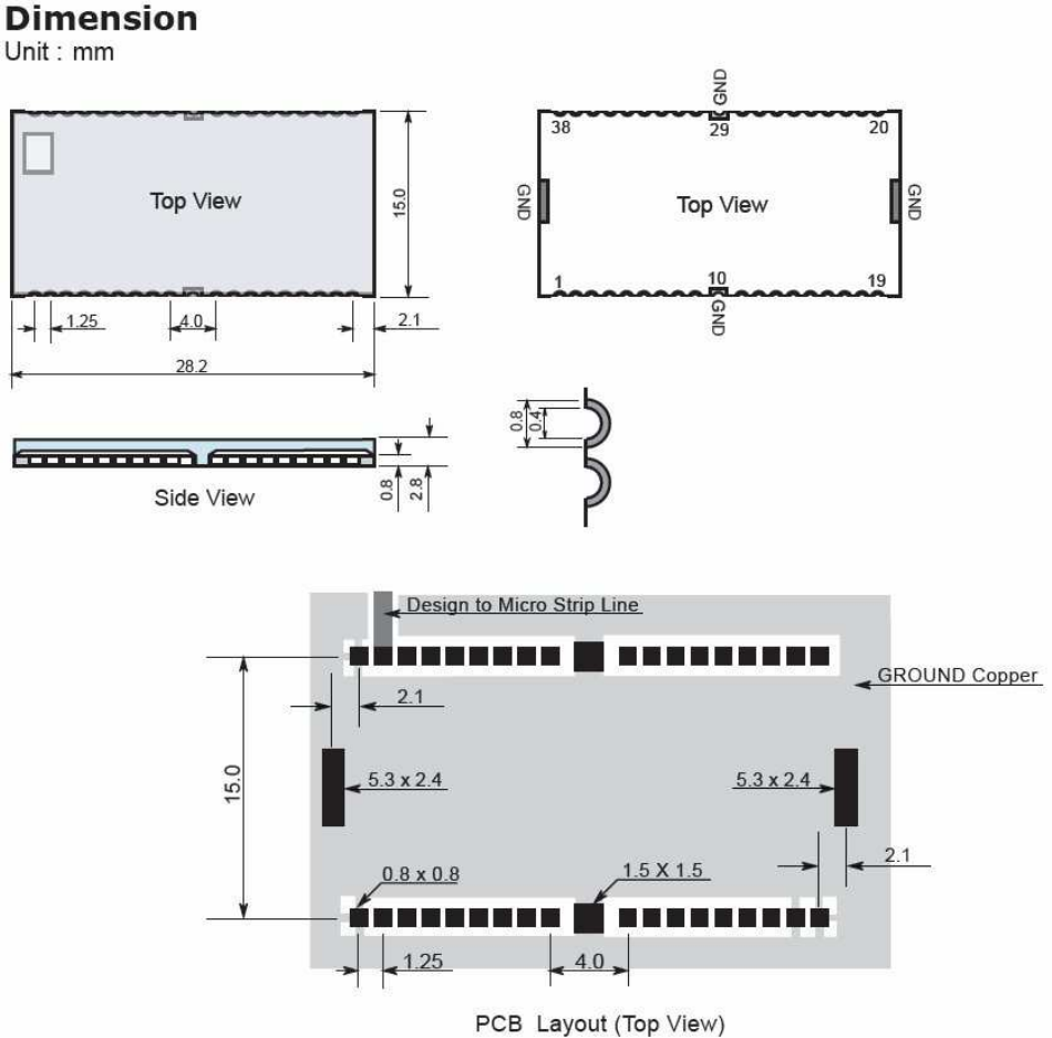
BTM-22x Dimension
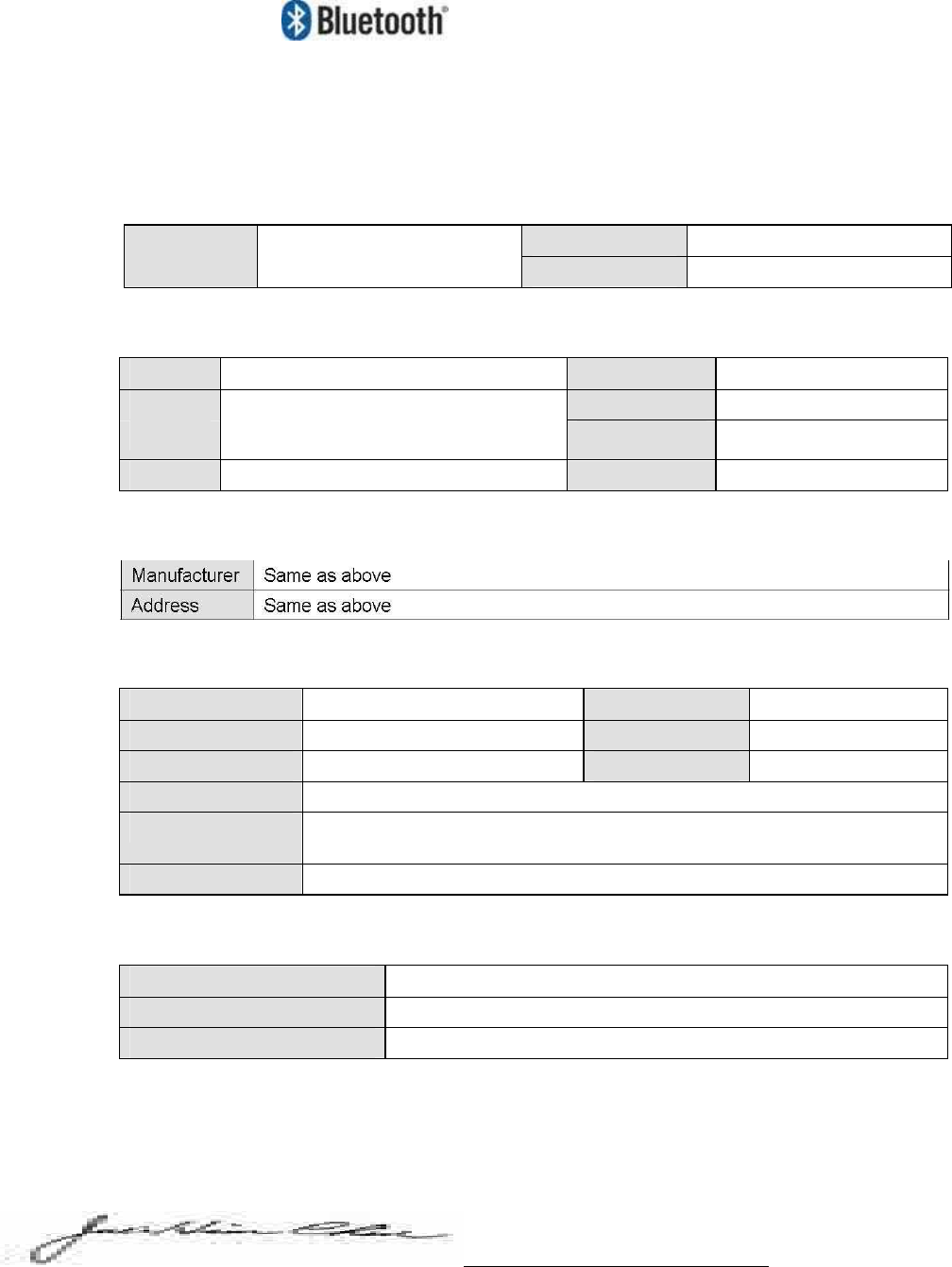
Qualified Product Notice
BQB: Juei-Hsin Chin
Hyper Taiwan Technology, Inc.
7F-1, No. 92, Sec.1 Nei-Hu Rd., Taipei Taiwan, R.O.C. 114
Assessment Date 11.10.2005
QPN Number QPNHTTJ050
Listing Date 11.10.2005
Applicant Information
Applicant Rayson Technology Co., Ltd Contact Person Tim Lin
Address 1F, No. 9, R&D Rd. 2, Science-Based Phone Number +886.3.563.3666
Industrial Park, Hsin-Chu, 300 Taiwan, R.O.C Fax Number +886.3.563.3688
URL http://www.rayson.com Email Address sales@mail.rayson.com
Manufacturer Information
Product Information
Product Name Class 1 Module Product Category Components
Product ID BTM-22x, BTM-23x Product Type Comp-HW-Integrated
Hardware Version A1 Software Version N/A
Firmware Version cyt_8unified_fl_bt2.0_19p2
Supported Protocol RF, BB, LM, HCI, HCI-USB, HCI-RS232, HCI-UART, L2CAP, SDP, RFCOMM
Supported Profile GAP, SPP
Reference Information
Product Reference Document V1.0
Bluetooth Specification V2.0 + EDR
Test Case Reference List TCRL_EDR_2005-1-BQRB1, TCRL_P1_1_2005-1-BQRB1
I certify that the Class 1Module has a Bluetooth Brand License based on the requirements as described in Section 6.2.1,
Pre-Tested Bluetooth Components, of the Bluetooth Program Reference Document 1.0
San Lorenzo, California / 11.10.2005
BTM-222 Regulation Statement
---------------------------------------
In accordance with FCC Part 15C BTM222, this module is listed as a Limited Modular Transmitter device.
Therefore, the final host product must be submitted to Rayson Technology Co., Ltd. for confirmation that the
installation of the module into the host is in compliance with the regulations of FCC and IC Canada.
Specifically, if an antenna other than the model documented in the Filing is used, a Class 2 Permissive
Change must be filed with the FCC.
Changes or modifications not expressly approved by the manufacturer could void the user’s authority to
operate the equipment.
IV. FCC Label Instructions
The outside of final products that contains this module device must display a label
referring to the enclosed module. This exterior label can use wording such as the
following: “Contains Transmitter Module FCC ID: QWOBTM-22X” or “Contains FCC ID:
QWOBTM-22X.” Any similar wording that expresses the same meaning may be used.