Raytek Mi Miniature Infrared Sensor Users Manual MI_MA_54301_ENG_RevF
MI Miniature Infrared Sensor to the manual b099b4de-05d2-4ce1-9d78-6674b5006fc2
2015-02-06
: Raytek Raytek-Mi-Miniature-Infrared-Sensor-Users-Manual-502388 raytek-mi-miniature-infrared-sensor-users-manual-502388 raytek pdf
Open the PDF directly: View PDF ![]() .
.
Page Count: 95
- 1 Safety Instructions
- 2 Description
- 3 Technical Data
- 3.1 Measurement Specifications
- 3.2 Optical Specifications
- 3.3 Electrical Specifications
- 3.4 Environmental Specifications
- 3.5 Dimensions
- 3.6 Scope of Delivery
- 4 Basics
- 5 Installation
- 6 Operation
- 7 Options
- 8 Accessories
- 9 Maintenance
- 10 Software
- 11 Programming Guide
- 12 Appendix
- Index

MI
Miniature Infrared Sensor
Operating Instructions
Rev. F 04/2006
54301

DeclarationofConformityfortheEuropeanCommunit
y
Thisinstrumentconformsto:
EMC:IEC/EN61326‐1
Safety:EN61010‐1:1993/A2:1995

Contacts
Europe
RaytekGmbH
13127Berlin,Germany
BlankenburgerStr.135
Tel:+4930478008–0
+4930478008–400
Fax:+49304710251
raytek@raytek.de
USA
RaytekCorporation
CA95061–1820,SantaCruz
1201ShafferRd.POBox1820
Tel:+1831458–1110or
+1800227–8074
Fax:+1831458–1239
automation@raytek.com
UnitedKingdom
Tel:+441908630800
Fax:+441908630900
ukinfo@raytek.com
France
Tel:0800888244
info@raytek.fr
RaytekChinaCompany
Beijing,China
Tel:+861064392255
Fax:+861064370285
info@raytek.com.cn
Internet:http://www.raytek.com/
©RaytekCorporation.
Raytek,theRaytekLogo,andDataTempareregisteredtrademarksofRaytekCorporation.
Allrightsreserved.Specificationssubjecttochangewithoutnotice.

WARRANTY
Themanufacturerwarrantsthisinstrumenttobefreefromdefectsin
materialandworkmanshipundernormaluseandserviceforthe
periodoftwoyearsfromdateofpurchase.Thiswarrantyextends
onlytotheoriginalpurchaser.Thiswarrantyshallnotapplytofuses,
batteries,oranyproductthathasbeensubjecttomisuse,neglect,
accident,orabnormalconditionsofoperation.
Intheeventoffailureofaproductcoveredbythiswarranty,the
manufacturerwillrepairtheinstrumentwhenitisreturnedbythe
purchaser,freightprepaid,toanauthorizedServiceFacilitywithin
theapplicablewarrantyperiod,providedmanufacturer’s
examinationdisclosestoitssatisfactionthattheproductwas
defective.Themanufacturermay,atitsoption,replacetheproductin
lieuofrepair.Withregardtoanycoveredproductreturnedwithin
theapplicablewarrantyperiod,repairsorreplacementwillbemade
withoutchargeandwithreturnfreightpaidbythemanufacturer,
unlessthefailurewascausedbymisuse,neglect,accident,or
abnormalconditionsofoperationorstorage,inwhichcaserepairs
willbebilledatareasonablecost.Insuchacase,anestimatewillbe
submittedbeforeworkisstarted,ifrequested.
THEFOREGOINGWARRANTYISINLIEUOFALLOTHER
WARRANTIES,EXPRESSEDORIMPLIED,INCLUDINGBUT
NOTLIMITEDTOANYIMPLIEDWARRANTYOF
MERCHANTABILITY,FITNESS,ORADEQUACYFORANY
PARTICULARPURPOSEORUSE.THEMANUFACTURER
SHALLNOTBELIABLEFORANYSPECIAL,INCIDENTALOR
CONSEQUENTIALDAMAGES,WHETHERINCONTRACT,
TORT,OROTHERWISE.

TABLEOFCONTENTS
1SAFETYINSTRUCTIONS............................................1
2DESCRIPTION ...............................................................3
3TECHNICALDATA ......................................................4
3.1MEASUREMENTSPECIFICATIONS ...............................4
3.2OPTICALSPECIFICATIONS ..........................................6
3.3ELECTRICALSPECIFICATIONS ....................................7
3.4ENVIRONMENTALSPECIFICATIONS ...........................8
3.5DIMENSIONS...............................................................9
3.6SCOPEOFDELIVERY .................................................10
4BASICS...........................................................................11
4.1MEASUREMENTOFINFRAREDTEMPERATURE.........11
4.2EMISSIVITYOFTARGETOBJECT................................12
4.3AMBIENTTEMPERATURE .........................................12
4.4ATMOSPHERICQUALITY ..........................................12
4.5ELECTRICALINTERFERENCE ....................................13
5INSTALLATION ..........................................................14
5.1POSITIONING ............................................................14
5.1.1DistancetoObject.............................................14
5.2WIRING.....................................................................15
5.2.1SensorHeadCable ............................................15
5.2.2CablePreparations ............................................16
5.3OUTPUTS...................................................................18

5.3.1SignalOutput................................................... 19
5.3.2HeadAmbientTemp./AlarmOutput ............. 20
5.3.3ThermocoupleOutput....................................... 22
5.4INPUTSFTC.............................................................. 23
5.4.1EmissivitySetting(analogcontrolled) ............. 24
5.4.2EmissivitySetting(digitalcontrolled) ............. 25
5.4.3AmbientBackgroundTemperature
Compensation ............................................................ 26
5.4.4TriggerandHoldFunction............................... 28
5.5CONNECTINGTOTHEPCVIARS232 ...................... 30
5.6INSTALLINGOFMULTIPLESENSORSVIARS485...... 31
6OPERATION................................................................. 34
6.1CONTROLPANEL ..................................................... 34
6.2SETTINGOFMODES.................................................. 35
6.3SETTINGTHEOUTPUTJUMPER ................................ 35
6.4POSTPROCESSING .................................................... 38
6.4.1Averaging ......................................................... 38
6.4.2PeakHold.......................................................... 40
6.4.3ValleyHold ....................................................... 41
6.4.4AdvancedPeakHold......................................... 42
6.4.5AdvancedValleyHold ...................................... 43
6.4.6AdvancedPeakHoldwithAveraging............... 43
6.4.7AdvancedValleyHoldwithAveraging............ 43
6.5FACTORYDEFAULTS ................................................ 44
7OPTIONS....................................................................... 45

8ACCESSORIES .............................................................46
8.1OVERVIEW ................................................................46
8.2ADJUSTABLEMOUNTINGBRACKET.........................48
8.3FIXEDMOUNTINGBRACKET ....................................49
8.4AIRPURGINGJACKET...............................................50
8.5AIRCOOLINGSYSTEM..............................................52
8.6RIGHTANGLEMIRROR ............................................57
8.7BOXLID ....................................................................58
8.8PROTECTIVEWINDOW .............................................59
9MAINTENANCE..........................................................60
9.1TROUBLESHOOTINGMINORPROBLEMS ..................60
9.2FAIL‐SAFEOPERATION ............................................61
9.3SENSINGHEADEXCHANGE .....................................63
10SOFTWARE .................................................................65
11PROGRAMMINGGUIDE .......................................66
11.1TRANSFERMODES ..................................................67
11.2GENERALCOMMANDSTRUCTURE ........................68
11.3DEVICEINFORMATION...........................................69
11.4DEVICESETUP ........................................................70
11.4.1TemperatureCalculation ................................70
11.4.2EmissivitySettingandAlarmSetpoints .......70
11.4.3PostProcessing ...............................................72
11.5DYNAMICDATA.....................................................72
11.6DEVICECONTROL ..................................................73
11.6.1OutputfortheTargetTemperature................73

11.6.2AnalogOutput,Scaling ................................. 73
11.6.3AlarmOutput................................................. 73
11.6.4Factorydefaultvalues..................................... 73
11.6.5LockMode....................................................... 74
11.6.6ModeSettingfortheDigitalInputFTC3....... 74
11.6.7ChangingtheSensingHeadCalibrationData74
11.6.8AmbientBackgroundTemperature
Compensation ............................................................ 74
11.7MULTIPLEUNITS(MULTIDROPMODE,RS485) .... 76
11.8COMMANDSET ...................................................... 77
12APPENDIX................................................................... 81
12.1DETERMINATIONOFEMISSIVITY ........................... 81
12.2TYPICALEMISSIVITYVALUES ................................ 83
INDEX ............................................................................... 87

SafetyInstructions
MI1
1SafetyInstructions
Thisdocumentcontainsimportantinformation,whichshouldbe
keptatalltimeswiththeinstrumentduringitsoperationallife.Other
usersofthisinstrumentshouldbegiventheseinstructionswiththe
instrument.Eventualupdatestothisinformationmustbeaddedto
theoriginaldocument.Theinstrumentshouldonlybeoperatedby
trainedpersonnelinaccordancewiththeseinstructionsandlocal
safetyregulations.
AcceptableOperation
Thisinstrumentisintendedonlyforthemeasurementof
temperature.Theinstrumentisappropriateforcontinuoususe.The
instrumentoperatesreliablyindemandingconditions,suchasin
highenvironmentaltemperatures,aslongasthedocumented
technicalspecificationsforallinstrumentcomponentsareadheredto.
Compliancewiththeoperatinginstructionsisnecessarytoensurethe
expectedresults.
UnacceptableOperation
Theinstrumentshouldnotbeusedformedicaldiagnosis.
ReplacementPartsandAccessories
Useonlyoriginalpartsandaccessoriesapprovedbythe
manufacturer.Theuseofotherproductscancompromisethe
operationalsafetyandfunctionalityoftheinstrument.
InstrumentDisposal
Disposalofoldinstrumentsshouldbehandledaccordingto
professionalandenvironmentalregulationsaselectronicwaste.

SafetyInstructions
2MI
OperatingInstructions
Thefollowingsymbolsareusedtohighlightessentialsafety
informationintheoperationinstructions:
Helpfulinformationregardingtheoptimaluseofthe
instrument.
Warningsconcerningoperationtoavoidinstrument
damage.
Warningsconcerningoperationtoavoidpersonalinjury.
Payparticularattentiontothefollowingsafetyinstructions.
Usein110/230VACelectricalsystemscanresultin
electricalhazardsandpersonalinjuryifnotproperly
protected.Allinstrumentpartssuppliedbyelectricitymust
becoveredtopreventphysicalcontactandotherhazardsat
alltimes.

Description
MI3
2Description
TheminiatureinfraredsensorsMIarenoncontactinfrared
temperaturemeasurementsystems.Theyaccuratelyandrepeatably
measuretheamountofenergyemittedfromanobjectandconvert
thatenergyintoatemperaturesignal.
Thefollowingoutputsareavailable:
• J‐Thermocouple
• K‐Thermocouple
• 0‐5Volt
• 0‐20mAor4‐20mA
• 10mV/°Cheadambienttemperaturesignal
• RS232interface
• optional:RS485interface
ThesensingheadisprotectedbyaruggedIEC529(IP65,NEMA‐4)
stainlesssteelhousing,andisconnectedtotheelectronicboxwitha
1m(3ft)cable.Longercablesmustbeorderedasanoption.The
electronicboxisseparatedfromthesensinghead.Thisallowsthe
sensingheadtobeusedinhotenvironmentsupto180°C(356°F)
withoutcooling.Theelectronicboxcanonlybeusedinambient
temperaturesupto65°C(150°F).
MIwillallowsensingheadstobeinterchangedbyprogrammingin
theuniquecalibrationdataassociatedwithdifferentheads.Take
specialcareforthesensingheadcalibrationdataprintedonthecable!

TechnicalData
4MI
3TechnicalData
3.1MeasurementSpecifications
TemperatureRange
LT‐40to600°C(‐40to1112°F)
forJ‐Thermocouple:‐25to600°C(‐13to1112°F)
SpectralResponse
LT8to14μm
ResponseTime
Allmodels150ms(95%response)
Accuracy
LT±1%or±1°C(±2°F)whicheverisgreater
LT±2°C(±4°F)fortargettemp.<20°C(68°F)
TCoutputs±1%or±2.5°C(±5°F)whicheverisgreater
Atambienttemperature23°C±5°C(73°F±9°F)
Repeatability
Allmodels±0.5%or±0.5°C(±1°F)whicheverisgreater

TechnicalData
MI5
TemperatureResolution
LT±0.1K(±0.2°F)*
±0.25K(±0.5°F)**
*Forazoomedtemperaturespanof300°C(600°F)
**Forthefulltemperaturerangeoftheunit
TemperatureCoefficient
MIC±0.05KperKor±0,05%/Kwhicheveris
greater,atambient:23to125°C(73to185°F)
MIH±0.05KperKor±0,05%/Kwhicheveris
greater,atambient:23to180°C(73to356°F)
MIC,MIH±0.1KperKor±0.1%perKwhicheveris
greater,atambient:0to23°C(32to73°F)
MID±0.15KperKor±0.15%perKwhicheveris
greater,atambient:0to85°C(32to185°F)
Box±0.1KperKor±0.1%perKwhicheveris
greater
ThermalShock(within20min.)
LT±3.5KatΔTambient=25K(45°F)
attargettemperatureof50°C(45°F)
Emissivity
Allmodels0.100to1.100
Transmission
Allmodels0.100to1.000
TechnicalData
6MI
3.2OpticalSpecifications
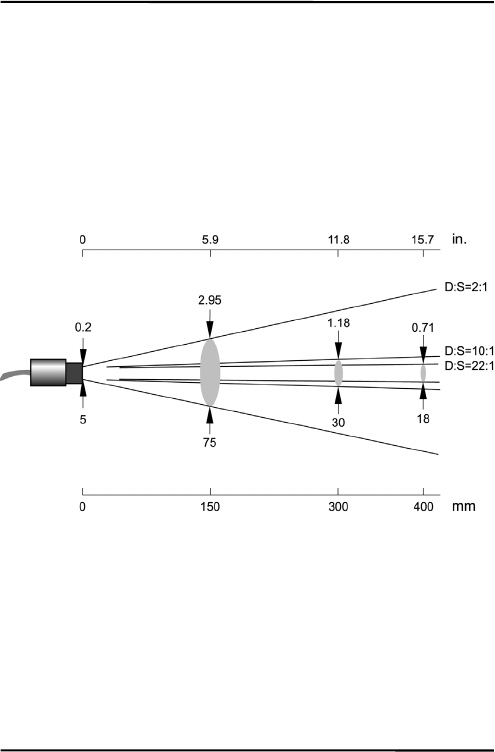
OpticalResolutionD:S
MID,MIC;MIH22:1(typ.),21:1(guaranteed)
MID,MIC;MIH10:1
MID,MIC2:1
At90%energyinminimumanddistance400mm(15.7in.)
Figure1:SpotSizeChart

TechnicalData
MI7
3.3ElectricalSpecifications
PowerSupply
Voltage12to26VDC
Current100mA
Outputs
1.Output(OUT)0to20mA,or
4to20mA,or
0to5V,or
Thermocouple(JorK)
2.Output(AMB)0to5Voutputforheadambienttemperature
(0to500°C,32to932°F)oroutputforalarm
relay(softwareenabled,onlyinconjunction
withRS232/485)
mAOutputrecommendedloopimpedanceseeFigure9on
page19.
0to5VOutputsmin.loadimpedance100kΩ(alowerload
impedancedeterioratestheaccuracy)
outputimpedance100Ω
shortcircuitresistant
Thermocoupleoutputimpedance20Ω
shortcircuitresistant

TechnicalData
8MI
3.4EnvironmentalSpecifications
AmbientTemperature
MIHsensinghead0to180°C(32to356°F)
MICsensinghead0to125°C(32to257°F)
MIDsensinghead0to85°C(32to185°F)
MIDwithaircooling‐18to200°C(0to392°F)
Electronicsbox0to65°C(32to150°F)
StorageTemperature‐10to85°C(14to185°F)
Rating(Head)IP65(NEMA‐4),notformodelswithan
opticalresolutionof2:1
Rating(Box)IP65(NEMA‐4)
RelativeHumidity10%to95%non‐condensing
EMCIEC61326‐1
max.cablelength3m(118in.)
Vibration(Head)IEC60068‐2‐6:2G,10to150Hz,3axes
Shock(Head)IEC60068‐2‐27:50G,11ms,3axes
Weight(Head)50g(2oz.)with1mcable,stainlesssteel
Weight(Box)270g(10oz.),die‐castzinc
HeadCableMaterial
MID/MICPUR(Polyurethane),Halogenfree,
Siliconefree
MIHTeflon®
Teflondevelopspoisonousgasseswhenitcomesinto
contactwithflames!
TechnicalData
MI9
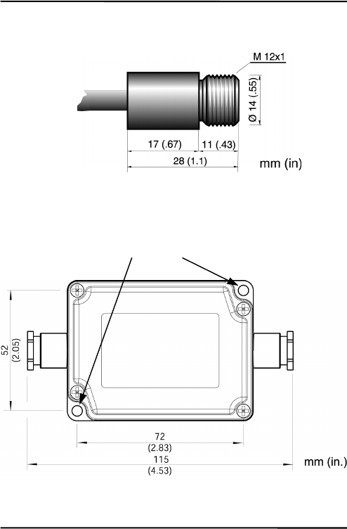
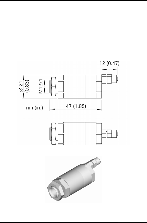
3.5Dimensions
Figure2:DimensionsofSensingHead
Standard cable length
1 m (3 ft.)
MID/MIC: Ø 5 mm (0.2 in)
MIH: Ø 3 mm (0.12 in)
2 mounting holes,
Ø 4.5 mm
(
0.17 in
)
TechnicalData
10MI
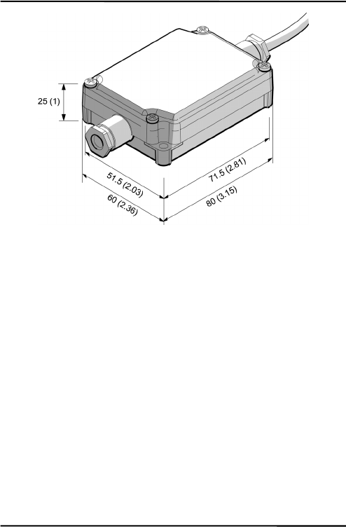
Figure3:DimensionsofElectronicBox
3.6ScopeofDelivery
Thescopeofdeliveryincludesthefollowing:
• Sensinghead
• 1mheadcable
• Mountingnut
• Electronicbox
• Operatinginstructions

Basics
MI11
4Basics
4.1MeasurementofInfraredTemperature
AllsurfacesemitinfraredradiationTheintensityofthisinfrared
radiationchangesaccordingtothetemperatureoftheobject.
Dependingonthematerialandsurfaceproperties,theemitted
radiationliesinawavelengthspectrumofapproximately1to20μm.
Theintensityoftheinfraredradiation(”heatradiation”)isdependent
onthematerial.Formanysubstancesthismaterial‐dependent
constantisknown.Thisconstantisreferredtoasthe”emissivity
value”.
Infraredthermometersareoptical‐electronicsensors.Thesesensors
aresensitivetotheemittedradiation.Infraredthermometersare
madeupofalens,aspectralfilter,asensor,andanelectronicsignal
processingunit.Thetaskofthespectralfilteristoselectthe
wavelengthspectrumofinterest.Thesensorconvertstheinfrared
radiationintoanelectricalsignal.Thesignalprocessingelectronics
analyzetheelectricalsignalsandconvertitintoatemperature
measurement.Astheintensityoftheemittedinfraredradiationis
dependentonthematerial,therequiredemissivitycanbeselectedon
thesensor.
Thebiggestadvantageoftheinfraredthermometerisitsabilityto
measuretemperaturewithouttouchinganobject.Consequently,
surfacetemperaturesofmovingorhardtoreachobjectscaneasilybe
measured.

Basics
12MI
4.2EmissivityofTargetObject
Todeterminetheemissivityofthetargetobjectrefertosection12.1
DeterminationofEmissivityonpage81.Ifemissivityislow,
measuredresultscouldbefalsifiedbyinterferinginfraredradiation
frombackgroundobjects(suchasheatingsystems,flames,fireclay
bricks,etc.closebesideorbehindthetargetobject).Thistypeof
problemcanoccurwhenmeasuringreflectivesurfacesandverythin
materialssuchasplasticfilmsandglass.
Thismeasurementerrorcanbereducedtoaminimumifparticular
careistakenduringinstallation,andthesensingheadisshielded
fromthesereflectingradiationsources.
4.3AmbientTemperature
Thesensingheadwasdevelopedforthefollowingambient
temperatureranges:
• MIH:0to180°C(32to356°F)
• MIC:0to125°C(32to257°F)
• MID:0to85°C(32to185°F)
TheMIDcanoperateinambienttemperaturesupto200°C(392°F)
withtheair‐coolingaccessory.
4.4AtmosphericQuality
Ifthelensgetsdirty,infraredenergywillbeblockedandthe
instrumentwillnotmeasureaccurately.Itisgoodpracticetoalways
keepthelensclean.TheAirPurgeJackethelpskeepcontaminants
frombuildinguponthelens.Ifyouuseairpurging,makesurea
filteredairsupplywithcleandryairatthecorrectairpressureis
installedbeforeproceedingwiththesensorinstallation.

Basics
MI13
4.5ElectricalInterference
Tominimizeelectricalorelectromagneticinterferenceor“noise”be
awareofthefollowing:
• Mounttheunitasfarawayaspossiblefrompotentialsources
ofelectricalinterferencesuchasmotorizedequipment
producinglargesteploadchanges.
• Useshieldedwireforallinputandoutputconnections.
• Makesuretheshieldwiresareearthgroundedatonepoint.
• Sensorheadshieldbraidshouldmakedirectcontactaround
thecablecircumference.

Installation
14MI
5Installation
5.1Positioning
Sensorlocationdependsontheapplication.Beforedecidingona
location,youneedtobeawareoftheambienttemperatureofthe
location,theatmosphericqualityofthelocation,andthepossible
electromagneticinterferenceinthatlocation,accordingtothesections
describedabove.Ifyouplantouseairpurging,youneedtohavean
airconnectionavailable.Wiringandconduitrunsmustbe
considered,includingcomputerwiringandconnections,ifused.
5.1.1DistancetoObject
Thedesiredspotsizeonthetargetwilldeterminethemaximum
measurementdistance.Toavoiderroneousreadingsthetargetspot
sizemustcompletelyfilltheentirefieldofviewofthesensor.
Consequently,thesensormustbepositionedsothefieldofviewis
thesameasorsmallerthanthedesiredtargetsize.Foralist
indicatingtheavailableoptics,seesection3.2OpticalSpecifications
onpage6.
Theactualspotsizeforanydistancecanbecalculatedbyusingthe
followingformula.DividethedistanceDbyyourmodel’sD:S
number.Forexample,foraunitwithD:S=10:1,ifthesensoris
400mm(15.7in.)fromthetarget,divide400by10(15.7by10),which
givesyouatargetspotsizeofapproximately40mm(1.57in.).

Installation
MI15
Figure4:ProperSensorPlacement
5.2Wiring
5.2.1SensorHeadCable
Themanufacturerpreinstall’sthesensorheadcablebetweensensor
headandelectronicbox.Itmaybeshortenedbutnotlengthened.
Shorteningthecablelengthby1m(3ft.)causesa
temperatureerrorof–0.1K/m!
Donotbendthesensorheadcabletighterthan25mm/1in.
(MID/MIC)and15mm/0.6in.(MIH)respectively!
Target greater than spot size
Target equal to spot size
Target smaller than spot size
best good incorrect
Sensor
Installation
16MI
5.2.2CableforPowerSupplyandOutputs
Youneedtoconnectthepowersupply(12to26VDC)andthesignal
outputwires.Useonlycablewithoutsidediameterfrom4to6mm
(0.16to0.24in),AWG24.
Thecablemustincludeshieldedwires.Itshouldnotbe
usedasastrainrelief!
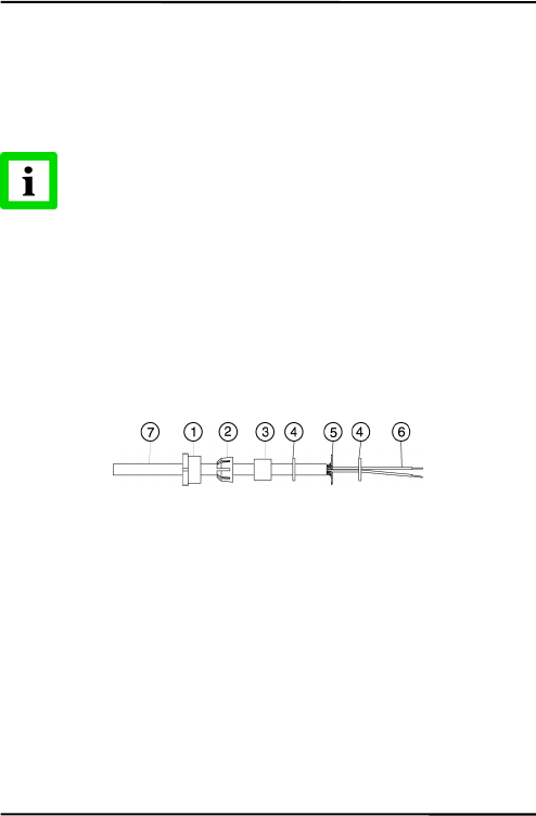
1.Cutabout40mm(1.5in)ofthecablesheath(7)fromtheend
ofthecable.Caution:Donotcutintotheshield!
2.Cuttheshield(5)soabout5mm(0.2in)remainsexposed
fromunderthecablesheath(7).Separatetheshieldand
spreadthestrandsout.Shortentheinsideinsulationuntil
youcanseparatethewires(6).
3.Strip3mm(0.15in)ofinsulationfromthewires(6).
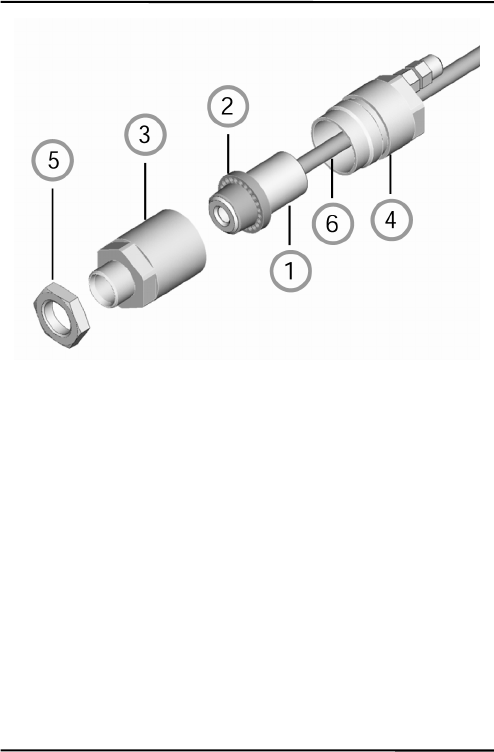
Figure5:CablePreparation
4.OpentheelectronicboxbyremovingthefourPhillipshead
screwsandpullingoffthelid.Unscrewthecap(1),and
removetheplasticcompressionfitting(2),therubberwasher
(3),whichisinsidethefitting,andthetwometalwashers(4).

Installation
MI17
Figure6:ConnectingofCablestotheElectronicBox
5.Putthefollowingonthecable(asshowninthefigureabove):
thecap(1),theplasticcompressionfitting(2),therubber
washer(3)andoneofthemetalwashers(4).
6.Spreadthecableshield(5)andthenslipthesecondmetal
washer(4)onthecable.Notethattheshieldmustmakegood
contacttobothmetalwashers.
7.Slipthewires(6)intotheelectronicboxfarenoughto
connecttothepowerandoutputterminals.
8.Screwthecap(1)intotheelectronicsbox.Tightensnuggly.
Donotovertighten.
9.Connectthewires(6)tothepowerandoutputterminalson
theprintedcircuitboard.
Cable that has to be
installed b
y
the user
Output signal and
p
ower connector bloc
k
Preinstalled cable
to sensor head
Installation
18MI
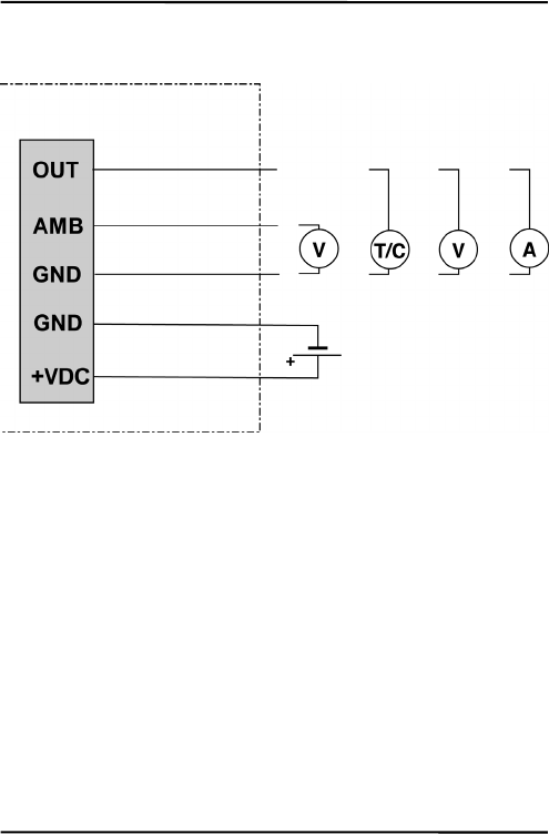
5.3Outputs
Figure7:SignalOutputsandPowerSupply
Electronic Box
Signal Output
Head Ambient Temp.
or Alarm
Power
0 to 5 V
J or K
0 to 5 V
4 to 20 m
A
0 to 20 m
A
12 to 26 VDC
Installation
MI19
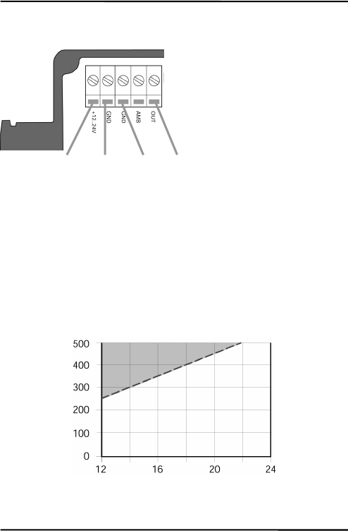
5.3.1SignalOutput
Figure8:WiringoftheSignalOutput(mAorV)
Thesignaloutputcanbeconfiguredeitherascurrentorasvoltage
output.
Theminimumloadimpedanceforthe0to5Voutputmustbe
100kΩ.
Themaximumcurrentloopimpedanceforthe0/4to20mAoutput
canbe500Ω,andthepowersupplyandloopimpedancemustbe
matchedasshownbelow.
Figure9:Max.LoopImpedancedependingonPowerSupply
Power + Power – Signal
Ground
Signal
Out
p
ut
Max. Loop Impedance [Ω]
Power
Supply
[V]
Max. Loop Impedance
Installation
20MI
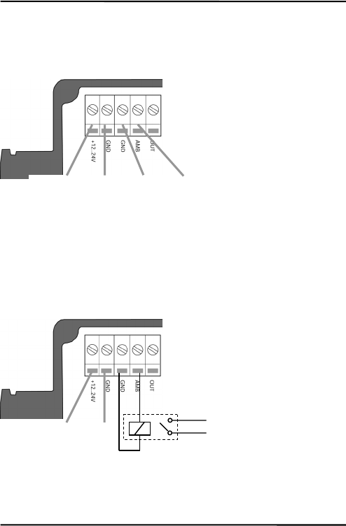
5.3.2HeadAmbientTemp./AlarmOutput
Thisoutputcanbeconfiguredeitherasoutputfortheheadambient
temperature(defaultconfiguration)orasanalarmoutput.
Figure10:WiringtheOutputforHeadAmbientTemperature
Theoutputrangefortheheadambienttemperatureis0to500°C
(32to932°F)with10mV/°C.
Incaseofanalarmtheoutputswitchesbetween0Vand5V.The
alarmoutputiscontrolledbythetargettemperatureorthesensing
headtemperature.
Figure11:WiringoftheAlarmOutput
Power -
Power +
Power + Power – Head Ambient Temp. Ground

Installation
MI21
Youmayuseasolidstaterelayforthealarmoutput.Theoutputis
shortcircuitresistantwith100Ωoutputimpedance.
ThealarmoutputisonlyenabledthroughtheDataTempMultiDrop
software,seethesoftwarehelpforsetupinstructions.
Installation
22MI
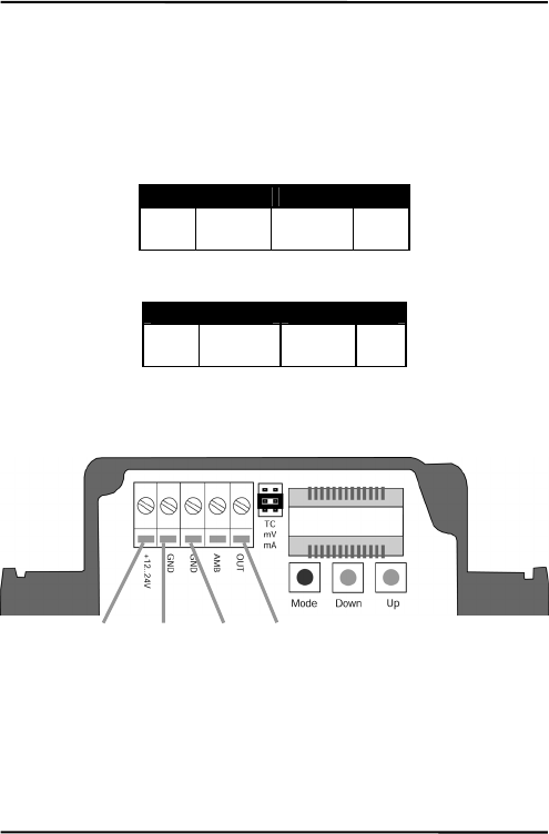
5.3.3ThermocoupleOutput
IfyouareusingaJ‐ orK‐ thermocoupleyoumustinstalla
compensationcable.Thecableisavailableasanaccessory
(XXXCI1CB25forTypeJ,XXXCI2CB25forTypeK)withacable
lengthof7.5m(24.6ft.)
Connectthewiresaccordingtothefollowingtable:
J-Thermocouple Power Supply
+
white
–
red-white
+
red-yellow
–
yellow
Table1:WiringtheThermocoupleJCompensationCable
K-Thermocouple Power Supply
+
yellow
–
red-yellow
+
red-white
–
white
Table2:WiringtheThermocoupleKCompensationCable
Figure12:WiringtheThermocoupleJCompensationCable
Power +
red-
y
ellow
Power
–
y
ellow
TC J
–
red-white
TC J +
white
Installation
MI23
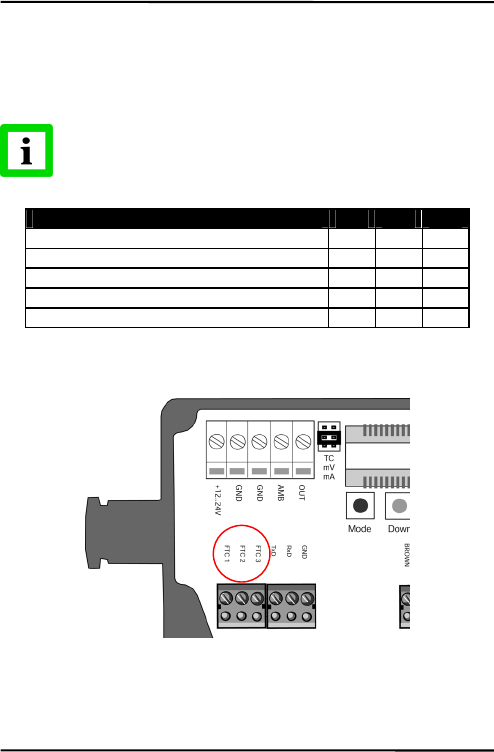
5.4InputsFTC
ThethreeinputsFTC1,FTC2,andFTC3areusedfortheexternal
controloftheunit.
AllinputfunctionsareenabledthroughtheDataTemp
MultiDropsoftwareonly,seethesoftwarehelpfor
completesetupinstructions!
FTC1 FTC2 FTC3
Emissivity (analog control) x
Emissivity (digital control) x x x
Ambient Background Temperature Compensation
x
Trigger x
Hold Function x
Table3:OverviewtotheFTCInputs
Figure13:FTCInputsontheElectronicBoard
Installation
24MI
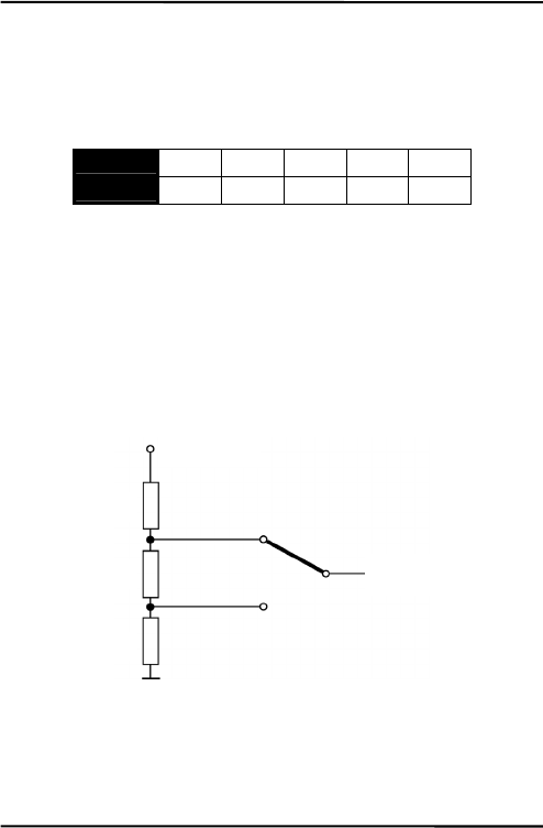
5.4.1EmissivitySetting(analogcontrolled)
TheinputFTC1canbeconfiguredtoacceptananalogvoltagesignal
(0to5VDC)toproviderealtimeemissivitysetting.Thefollowing
tableshowstherelationshipbetweeninputvoltageandemissivity.
U in V 0.0 0.5 … 4.5 5.0
Emissivity 0.1 0.2 … 1.0 1.1
Table4:RatiobetweenAnalogInputVoltageandEmissivity
Example:
Theprocessrequiresthesettingofemissivity:
• forproduct1:0.90
• forproduct2:0.40
Followingtheschemebelow,theoperatorneedsonlytoswitchto
position“product1”or“product2”.
Figure14:AdjustmentofEmissivityatInputFTC1(Example)
“product 1”
“product 2”
4.0 V (ε=0.9)
1.5 V (ε=0.4)
To the input FTC1
of the sensor
R1 = 200 Ω
R2 = 500 Ω
R3 = 300 Ω
+ 5 VDC

Installation
MI25
5.4.2EmissivitySetting(digitalcontrolled)
Thesensor’selectronicscontainsatablewith8pre‐installedsettings
foremissivity.Toactivatetheseemissivitysettings,youneedtohave
theinputsFTC1,FTC2,andFTC3connected.Accordingtothe
voltagelevelontheFTCinputs,oneofthetableentrieswillbe
activated.
0=Lowsignal(0V)
1=Highsignal(5V)
Anon‐wiredinputisconsideredas“High”!
Table entry Emissivity
(Examples) FTC3
FTC2
FTC1
0
1
2
3
4
5
6
7
1.100
0.500
0.600
0.700
0.800
0.970
1.000
0.950
0
0
0
0
1
1
1
1
0
0
1
1
0
0
1
1
0
1
0
1
0
1
0
1
Figure15:DigitalSelectionofEmissivitywithFTCInputs
Thevaluesinthetablecanonlybechangedbymeansofthe
DataTempMultiDropsoftware.

Installation
26MI
5.4.3AmbientBackgroundTemperatureCompensation
Thesensoriscapableofimprovingtheaccuracyoftarget
temperaturemeasurementsbytakingintoaccounttheambientor
backgroundtemperature.Thisfeatureisusefulwhenthetarget
emissivityisbelow1.0andthebackgroundtemperatureis
significantlyhotterthanthetargettemperature.Forinstance,the
highertemperatureofafurnacewallcouldleadtohotter
temperaturesbeingmeasuredespeciallyforlowemissivitytargets.
Ambientbackgroundtemperaturecompensationcompensatesforthe
impactofthereflectedradiationinaccordancetothereflective
behaviorofthetarget.Duetothesurfacestructureofthetarget,some
amountofambientradiationwillbereflectedandthereforeaddedto
thethermalradiationthatiscollectedbythesensor.Theambient
backgroundtemperaturecompensationcompensatesthefinalresult
bysubtractingtheamountofambientradiationmeasuredfromthe
sumofthermalradiationthesensorisexposedto.
Theambientbackgroundtemperaturecompensation
shouldalwaysbeactivatedincaseoflowemissivity
targetsmeasuredinhotenvironmentsorwhenheat
sourcesarenearthetarget!
Threepossibilitiesforambientbackgroundtemperature
compensationareavailable:
• Theinternalsensorheadtemperatureisutilizedfor
compensationassumingthattheambientbackground
temperatureismoreorlessrepresentedbytheinternalsensor
headtemperature.Thisisthedefaultsetting.
• Ifthebackgroundambienttemperatureisknownandconstant,
theusermaygivetheknownambienttemperatureasaconstant
temperaturevalue.

Installation
MI27
• Ambientbackgroundtemperaturecompensationfromasecond
temperaturesensor(infraredorcontacttemperaturesensor)
ensuresextremelyaccurateresults.Forexample,theoutputof
thesecondunit,setformVoutput,couldbeconnectedtothe
FTC2analoginput(0to5VDCcorrespondingtolowendand
highendoftemperaturerange)isutilizedforrealtime
compensation,wherebybothsensorsmustbesetonthesame
temperaturerange.
Figure16:PrincipleofAmbientBackgroundTemperature
Compensation
Sensor 2
targeted
to ambien
t
Sensor 1
targeted
to ob
j
ec
t
Thermal radiation
of ambient
Thermal radiation
of target
0
–
5 VDC
analog outpu
t
at FTC2 inpu
t
Furnace wall
Target object

Installation
28MI
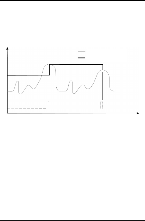
5.4.4TriggerandHoldFunction
TheFTC3inputcanbeusedasexternaltriggerinconjunctionwith
thesoftwaretriggermodesetting“Trigger”or“Hold”.
Figure17:WiringofFTC3asExternalInput
Trigger:AlogicallowsignalattheinputFTC3willresetthepeakor
valleyholdfunction.Aslongastheinputiskeptatlogicallowlevel
thesoftwarewilltransfertheactualobjecttemperaturestowardthe
output.Atthenextlogicalhighlevel,theholdfunctionwillbe
restarted.
Figure18:FTC3forResettingthePeakHoldFunction
External switch:
- contact relay,
- transistor,
- TTL gate, …
object temperature
output temperature
FTC3
Temp
Time
Installation
MI29
Hold:Thismodeactsasexternalgeneratedholdfunction.A
transitionattheinputFTC3fromlogicalhighleveltowardlogical
lowlevelwilltransferthecurrenttemperaturetowardtheoutput.
Thistemperaturewillbewrittentotheoutputuntilanewtransition
fromhightolowoccursattheinputFTC3.
Figure19:FTC3forHoldingtheOutputTemperature
object temperature
output temperature
Trigger
Temp
Time
Installation
30MI
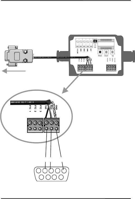
5.5ConnectingtothePCviaRS232
TheRS232interfacecomeswitheachmodel.Connectasingleunit
withaRS232COMportbyusingtheconnectionkitRAYMISCON.
Figure20:ConnectingtheRS232cable
2 3 5
Sub-D 9 pin
Transfer Mode:
• 9600 kBit/s
• 8 data bits
• 1 stop bit
• no parity
• no flow control
to the computer’s COM port
Installation
MI31
5.6InstallingofMultipleSensorsviaRS485
Thedistancebetweenthesensorandacomputercanbeupto1200m
(4000ft.)viaRS485interface.Thisallowsampledistancefromthe
harshenvironmentwherethesensingheadismountedtoacontrol
roomorpulpitwherethecomputerislocated.
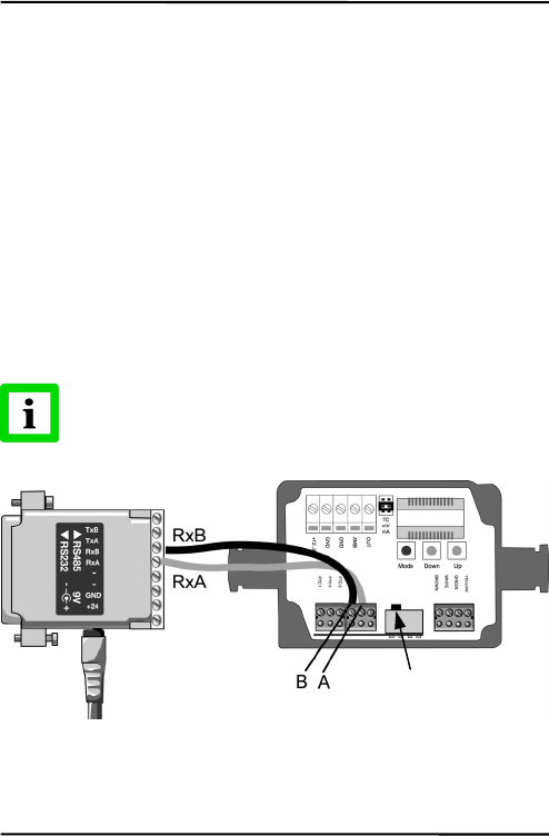
TheRS232/485adaptercomeswithapowersupply:
RAYMINCONV2for230VAC
RAYMINCONV1for110VAC
Connectthesignallineasshown:
RS232/485AdapterElectronicBox
RxBÆB
RxAÆA
Donotrunpowersupplyinthesameconduitasthe
RxA/RxBwires!
Figure21:WiringtheRS485Interface
Shunt deactivated!
Installation
32MI
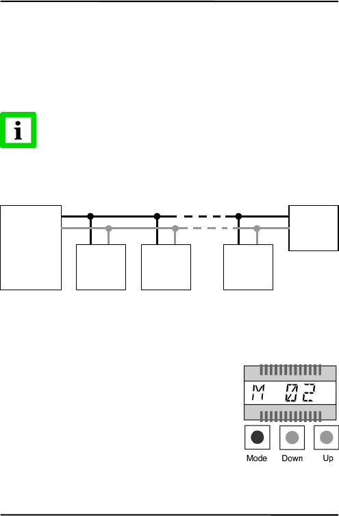
ForaninstallationoftwoormoresensorsinaRS485network,each
sensoriswiredparalleltotheothers.
Youmayconnectupto32units.Makesuretodeactivatethepreset
shuntresistorforallunitsexceptforthelastone.Thepositionofthe
switchtodeactivatetheshuntyoucanseeontheelectronicboardin
thefigureabove.
Beforeunitsareinanetworkthemultidropaddressneeds
tobedefined.Eachsensormusthaveauniqueaddress!
Thefollowingfigureillustratesthewiringofsensorsinamultidrop
installation.
Figure22:WiringtheRS485Network
Theaddresssettingcanbedoneeitherthroughbuttonsorthrough
softwarealternatively.
AddressingthroughButtons
Pressthe<Mode>buttonuntil“M”becomes
visible.Usethe<Down>and<Up>buttons
untiltherequestedaddressappears.Pressthe
<Mode>buttontoacknowledgeyourselection.
AddressingthroughSoftware
Alternativelythesensorcanbecontrolledbymeansoftheoptional
availablesoftwareDataTempMultiDrop.
RxB
Rx
A
RS232/485
A
dapter
unit 1 unit
before
last
last unit
with shunt
activated!
unit 2
A
A
A
A
B
B
B
B
Installation
MI33
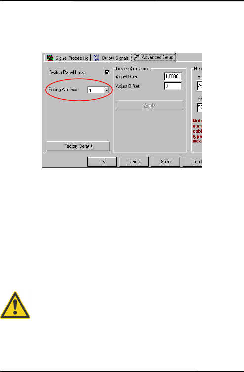
Gotothemenu<Setup><SensorSetup>,andthenselecttheregister
<AdvancedSetup>.Use<PollingAddress>forselectingtherequested
address.
Figure23:AddressSetting
Step‐by‐stepinstructionsforaddressingRS‐485MIunits:
1.Powertheunit.
2.Usingeitherthebuttonsorsoftware,assignuniqueaddress
tothesensor.
3.Powerdowntheunit.
4.Repeatuntilallsensorshaveauniqueaddress.
5.Onthelastunitinthenetwork,activatetheshuntresistor
aftertheunithasbeenpowereddown.
FailuretouseshieldedRS‐485wireoractivationofthe
shuntresistorwhentheunitispowered,canresultin
damagetotheelectronics!

Operation
34MI
6Operation
Onceyouhavethesensorpositionedandconnectedproperly,the
systemisreadyforcontinuousoperation.
Theoperationofthesensorcanbedonebymeansofthebuilt‐in
controlpanelonthesensor’selectronicboardorbymeansofthe
softwarethatcamewithyoursensoroptionally.
6.1ControlPanel
Thesensorisequippedwithacontrolpanelinthesensor’selectronic
housing,whichhassetting/controllingbuttonsandanLCDdisplay.
Theactualfunctionmodeisshownonthedisplaywithaspecific
modesymbol.
Figure24:ControlPanel
Output Jumper
Mode Symbol
Value
Mode Button
Value Buttons
Operation
MI35
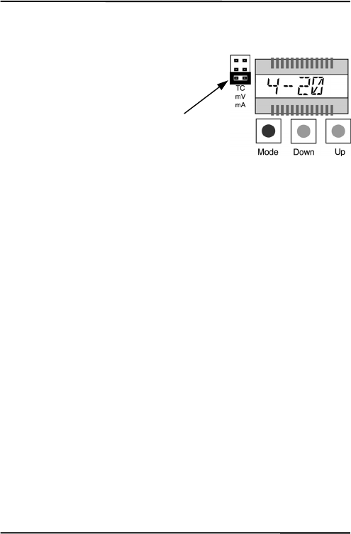
6.2SettingtheOutputJumper
Inadditiontothesetmodeinthe
unit,seesection6.3Settingof
Modes,onpage36,theunit’s
outputsmustbeconfiguredby
switchingthe<Output>jumper
inaccordancetotherequested
outputfunction(mA,mV,TC).
E.g.forthe“4to20mA”output,
the<Output>jumpermustbeset
tothebottompositionlabeled
with“mA”.
Operation
36MI
6.3SettingofModes
Youcaneasilydeterminetheunit’smodeorparameterbydoingthe
following:
Pressthe<Mode>buttonuntilthe
symbolfortheactualsetmodeappears
inthedisplay,e.g.<T>forsettingthe
transmission,seeTable5:Available
Modes,onpage37.
Usethe<Down/Up>buttonsuntilthe
requestedvaluecomesintoview.

Operation
MI37
DisplayMode Range
CTarget Temperature* (effected
by signal processing)
not adjustable
A Head Ambient Temperature not adjustable
T Target Temperature (not
effected by signal processing)
not adjustable
Output Mode mV mV output (default)
TCK thermocouple type K output
TCJ thermocouple type J output
4 - 20 4 - 20 mA current loop
0 - 20 0 - 20 mA current loop
E Emissivity 0.100 ... 1.000 (default: 0.950)
T Transmission 0.100 ... 1.000 (default: 1.000)
A Signal processing: Average** 0.100 ... 999.0
P Signal processing: Peak Hold** 0.100 ... 998.9 999 = infinite (P ∞)
V Signal processing: Valley Hold** 0.100 ... 998.9 999 = infinite (V ∞)
L Low end of range L = -40 ... 600**** (default: 0)
H High end of range H = -40 ... 600**** (default: 500)
U Temperature Unit °C or °F (default: °C)
M Multidrop Address*** 1 – 32, --- for address 0 (single unit)
*appears automatically after 10 s without any action
**not simultaneously
***only for units with RS485 interface
****temperatures according to LT head
Table5:AvailableModes

Operation
38MI
6.4PostProcessing
6.4.1Averaging
Averagingisusedtosmooththeoutputsignal.Thesignalis
smootheddependingonthedefinedtimebasis,wherebytheoutput
signaltracksthedetectorsignalwithsignificanttimedelaybutnoise
andshortpeaksaredamped.Usealongeraveragetimeformore
accuratedampingbehavior.Theaveragetimeistheamountoftime
theoutputsignalneedstoreach90%magnitudeofanobject
temperaturejump.
Figure25:Averaging
Alowlevelinput(GND)atexternalinputFTC3willpromptly
interrupttheaveragingandwillstartthecalculationagain.
Attention: Thedisadvantageofaveragingisthetimedelayofthe
outputsignal.Incaseofhavingatemperaturejumpattheinput(hot
output temperature
object temperature
temperature jump
average time
Temp
Time
90% of
temperature
j
ump

Operation
MI39
object),theoutputsignalreachesonly90%magnitudeoftheactual
objecttemperatureafterthedefinedaveragetime.
Operation
40MI
6.4.2PeakHold
Theoutputsignalfollowstheobjecttemperatureuntilamaximumis
found.Oncetheholdtimeisexceededtheoutputsignal,tracksand
outputtheactualobjecttemperatureandthealgorithmwillstartover
again.Therangefortheholdtimeis0.1to998.9s.
Figure26:PeakHold
Adefinedholdtimeof999s(symbol“∞”inthedisplay)willputthe
deviceintocontinuouspeakdetectionmode.
Alowlevelinput(GND)atexternalinputFTC3willpromptly
interrupttheholdtimeandwillstartthemaximumdetectionagain.
output temperature
object temperature
hold time
hold time
Temp
Time
Operation
MI41
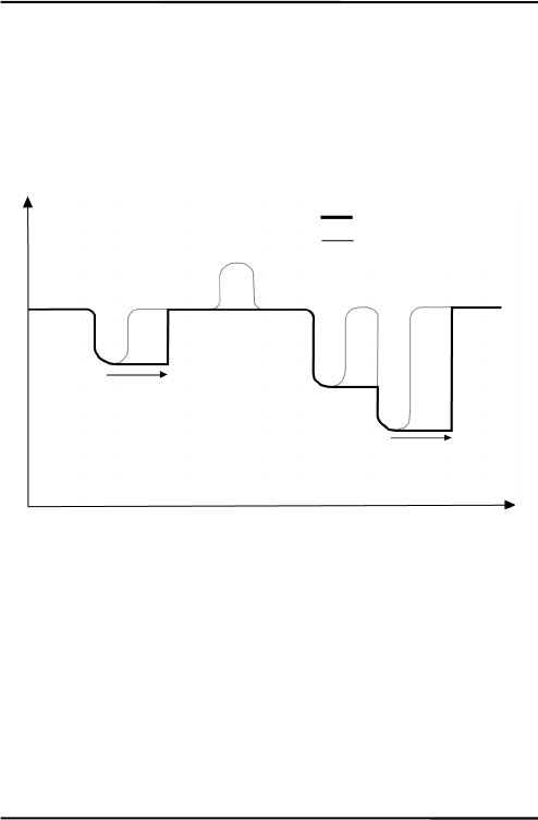
6.4.3ValleyHold
Theoutputsignalfollowstheobjecttemperatureuntilaminimumis
found.Oncetheholdtimeisexceededtheoutputsignal,tracksand
outputtheactualobjecttemperatureandthealgorithmwillstartover
again.Therangefortheholdtimeis0.1to998.9s.
Figure27:ValleyHold
Adefinedholdtimeof999s(symbol“∞”inthedisplay)willputthe
deviceintocontinuousvalleydetectionmode.
Alowlevelinput(GND)atexternalinputFTC3willpromptly
interrupttheholdtimeandwillstarttheminimumdetectionagain.
output temperature
object temperature
hold time
hold time
Temp
Time
Operation
42MI
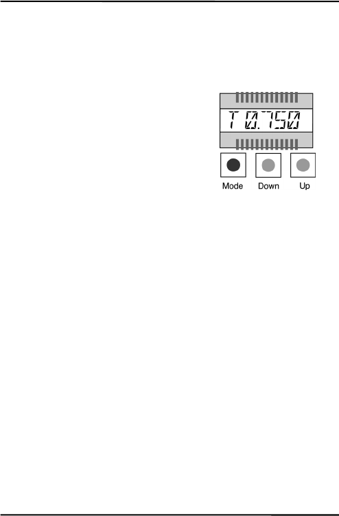
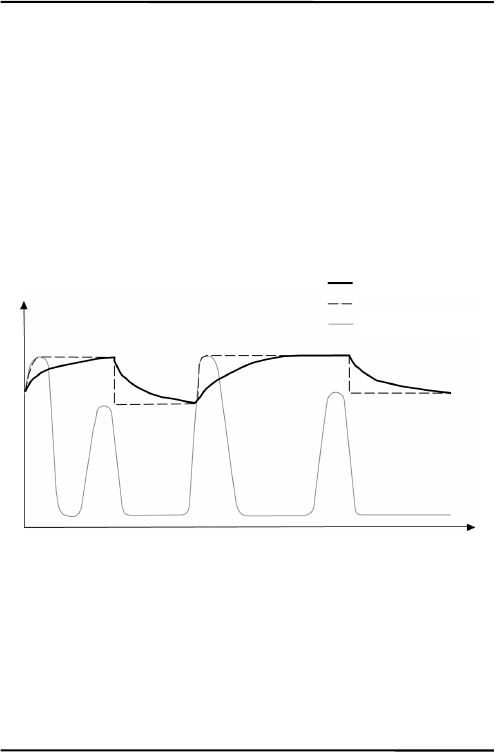
6.4.4AdvancedPeakHold
Thisfunctionsearchesthesensorsignalforalocalmaximum(peak)
andwritesthisvaluetotheoutputuntilanewlocalmaximumis
found.Beforethealgorithmrestartssearchingforalocalmaximum,
theobjecttemperaturehastodropbelowapredefinedthreshold.If
theobjecttemperatureraisesabovetheheldvaluewhichhasbeen
writtentotheoutputsofar,theoutputsignalfollowstheobject
temperatureagain.Ifthealgorithmdetectsalocalmaximumwhile
theobjecttemperatureiscurrentlybelowthepredefinedthreshold
theoutputsignaljumpstothenewmaximumtemperatureofthis
localmaximum.Oncetheactualtemperaturehaspassedamaximum
aboveacertainmagnitude,anewlocalmaximumisfound.This
magnitudeiscalledhysteresis.
Figure28:AdvancedPeakHold
Theadvancedpeakholdfunctionisonlyadjustablebymeansofthe
DataTempMultiDropSoftware.
output temperature
object temperature
hysteresis
threshold
Temp
Time
Operation
MI43
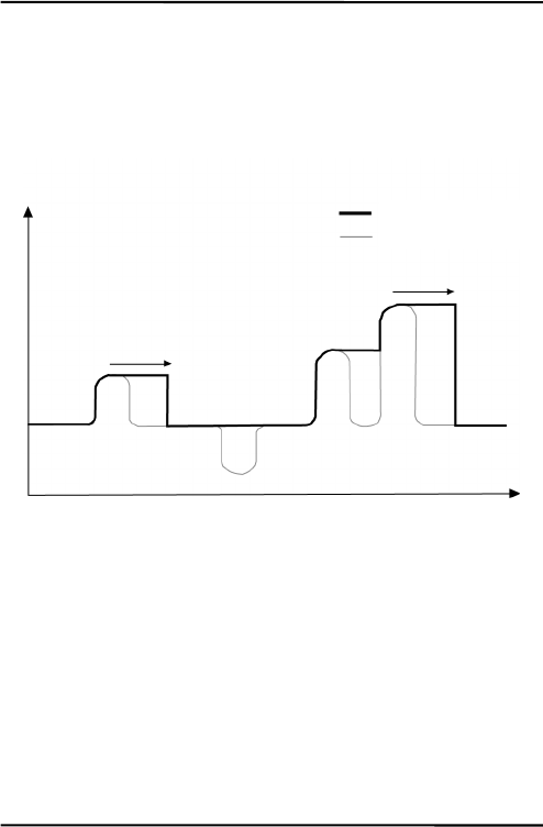
6.4.5AdvancedValleyHold
Thisfunctionworkssimilartotheadvancedpeakholdfunction,
exceptitwillsearchthesignalforalocalminimum.
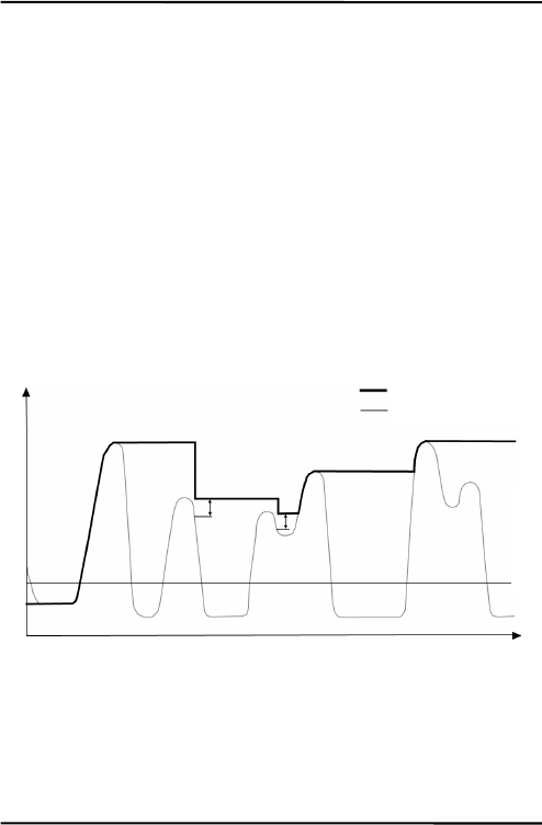
6.4.6AdvancedPeakHoldwithAveraging
Theoutputsignaldeliveredbytheadvancedpeakholdfunctions
tendstojumpupanddown.Thisisduetothefact,thatonly
maximumpointsoftheotherwisehomogenoustracewillbeshown.
Theusermaycombinethefunctionalityofthepeakholdfunction
withtheaveragingfunctionbychoosinganaveragetime,thus,
smoothingtheoutputsignalforconvenienttracing.
Figure29:AdvancedPeakHoldwithAveraging
Theadvancedpeakholdfunctionwithaveragingisonlyadjustable
bymeansoftheDataTempMultiDropSoftware.
6.4.7AdvancedValleyHoldwithAveraging
Thisfunctionworkssimilartotheadvancedpeakholdfunctionwith
averaging,exceptitwillsearchthesignalforalocalminimum.
output temperature
object temperature
Temp
Time
without averaging


Options
MI45
7Options
Optionsareitemsthatarefactoryinstalledandmustbespecifiedat
timeoforder.Thefollowingareavailable:
• Longercablelengths:3m/9.8ft.(…CB3),8m/26.2ft.(…CB8),
15m/49.2ft.(…CB15)
• RS485serialinterface(…4),formultidropnetworksorlong
distances
• Boxlidwithviewport(…V)

Accessories
46MI
8Accessories
8.1Overview
Afullrangeofaccessoriesforvariousapplicationsandindustrial
environmentsareavailable.Accessoriesincludeitemsthatmaybe
orderedatanytimeandaddedon‐site:
• AdjustableMountingBracket(XXXMIACAB)
• FixedMountingBracket(XXXMIACFB)
• AirPurgingJacket(XXXMIACAJ)
• AirCoolingSystemwith0.8m(2.6ft.)airhose
(XXXMIACCJ)orwith2.8m(9.2ft.)airhose(XXXMIACCJ1)
• RightAngleMirror(XXXMIACRAJ,XXXMIACRAJ1)
• BoxLid(XXXMIACV)
• ProtectiveWindow(XXXMIACPW)
• ProtectiveWindow,transmissionalreadysetintheunit
(XXXMIACPWI)
• PCconnectionkitformodelswithRS232,including
DataTempMultiDropSoftware(RAYMISCON)
• PCconnectionkitformodelswithRS485,including
DataTempMultiDropSoftwareandRS232/485converter:
110VAC(RAYMINCONV1)
230VAC(RAYMINCONV2)
Accessories
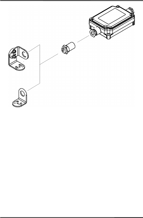
MI47
Figure30:StandardMountingAccessories
Sensing Head
Adjustable Bracket
Fixed Bracket
Electronic Box
Accessories
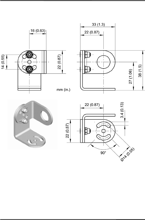
48MI
8.2AdjustableMountingBracket
Figure31:AdjustableMountingBracket(XXXMIACAB)
Accessories
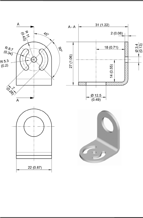
MI49
8.3FixedMountingBracket
Figure32:FixedMountingBracket(XXXMIACFB)
Accessories
50MI
8.4AirPurgingJacket
Theairpurgejacketisusedtokeepdust,moisture,airborneparticles,
andvaporsawayfromthesensinghead.Clean,oilfreeairis
recommended.Theairpurgejacketwithstandsambienttemperatures
upto180°C(356°F)andshouldnotbeusedforcoolingpurposes.The
recommendedairflowrateis30to60l/min(0.5to1cfm).Themax.
pressureis5bar.
Figure33:AirPurgingJacket(XXXMIACAJ)
Hose with inner
diameter of 3 mm
(0.12 in), outside
5
mm
(
0.2 in
)
Accessories
MI51
Figure34:MountingtheAirPurgeJacket
1.Removethesensor(1) andcablefromtheelectronicboxby
disconnectingthewiresfromtheelectronicbox.
2.OpentheAirPurgingJacket(3,4) andscrewthewhiteplastic
fitting(2) ontothesensoruptotheendofthethreads,donot
overtighten!
3.Slipthecable(6) throughthebackside(4) ofthejacket.
4.ClosetheAirPurgingJacket(3,4) andreconnectthewiresto
theelectronicboxandapplythemountingnut(5).
Accessories
52MI
8.5AirCoolingSystem
Thesensingheadcanoperateinambienttemperaturesupto200°C
(392°F)withtheair‐coolingsystem.Theair‐coolingsystemcomes
withaT‐adapterincluding0.8m/31.5in(optional:2.8m/110in)air
hoseandinsulation.TheT‐adapterallowstheair‐coolinghosetobe
installedwithoutinterruptingtheconnectionstothebox.
Theair‐coolingjacketmaybecombinedwiththerightanglemirror.
Figure35:AirCoolingSystem
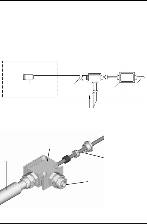
Figure36:ConnectingtheT‐Adapter(XXXMIACCJ)
max. ambient 200°C (392°F)
Sensing Head
max. ambient 50°C (122°F)
Air Hose T-
Adapter
Electronic
Housin
g
Cable
Air cooling (max. 35°C / 95°F)
Hose to
sensing head
T-Adapter
Cable to electronic
housing
Fitting free for air connection
Hose:
inner Ø: 9 mm (0.35 in)
outer Ø: 12
mm
(
0.47 in
)
Accessories
MI53
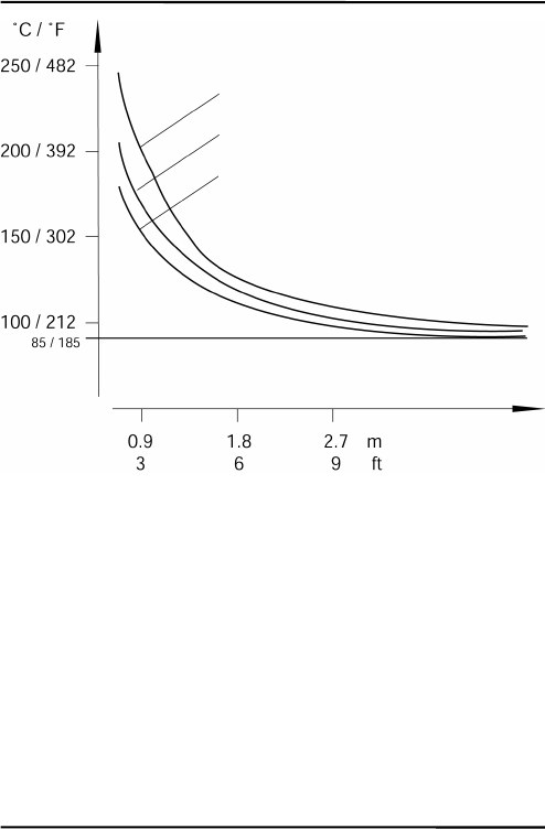
Figure37:MaximumAmbientTemperaturedependingon
AirFlowandHoseLength
Note:“HoseLength“isthelengthofhoseexposedtohighambient
temperature(nottheoveralllengthofthehose).
Hose Length
60 l / min (2.1 cubic feet per minute)
Air Flow:
50 l / min (1.8 cfm)
40 l / min (1.4 cfm)

Accessories
54MI
Figure38:AirCoolingSystem:PurgingJacket
TheAirCoolingSystemconsistsof:
(1)sensinghead
(2)innerplasticfitting(airpurgingjacket)
(3)frontpartoftheair‐purgingjacket
(4)backpartoftheair‐purgingjacket
(5)mountingnut
(6)preinstalledcablebetweensensorandbox,leadingthroughthe
T‐adapter
(7)hoseconnectingnut
(8)innerhose
(9)outerhose
(10)T‐adapter
(11)rubberwasher
(12)plasticcompressionfitting
(13)cap

Accessories
MI55
Figure39:AirCoolingSystem:T‐Adapter

Accessories
56MI
Figure40:DimensionsofAirCoolingSystem
Hose:
inner Ø: 9 mm (0.35 in)
outer Ø: 12 mm (0.47 in)

Accessories
MI57
8.6RightAngleMirror
Therightanglemirrorcomesintwodifferentversions:
XXXMIACRAJrightanglemirrorasaccessoryforairpurging
jacketoraircoolingsystem
XXXMIACRAJ1rightanglemirrorwithintegratedairpurging
Figure41:RightAngleMirrorXXXMIACRAJ(left),
RightAngleMirrorwithAirPurgingXXXMIACRAJ1(right)
Therightanglemirrorwithstandsambienttemperaturesupto180°C
(356°F).
Formountingtherightanglemirror(XXXMIACRAJ)seesection8.4
AirPurgingJacketonpage50.However,insteadofusingthefront
partoftheairpurgingjacket(3),mounttherightanglemirror.
Figure42:RightAngleMirror(*withAirPurging)

Accessories
58MI
8.7BoxLid
Figure43:BoxLidwithViewPortforPostInstallations
(XXXMIACV)
Accessories
MI59
8.8ProtectiveWindow
Theprotectivewindowcanbeusedtoprotectthesensingheadfrom
dustandothercontamination.Thisshouldbeappliedespeciallyfor
sensorswithoutalens.Theseareallmodelswithanoptical
resolutionof2:1.
Theprotectivewindowismadefromnon‐poisonouszincsulfide,
withatransmissionfactorof0.75±0.05.Ithasanouterdiameterof
17mm(0.67in).Theprotectivewindowcanbedirectlyscrewedto
thesensinghead.Itwithstandsambienttemperaturesupto180°C
(356°F).
Forcorrecttemperaturereadings,thetransmissionofthe
protectivewindowmustbesetviathecontrolpanelinthe
sensor’selectronichousing,seesection6.2Settingof
Modesonpage35!
Figure44:ProtectiveWindow(XXXMIACPW)

Maintenance
60MI
9Maintenance
Oursalesrepresentativesandcustomerservicearealwaysatyour
disposalforquestionsregardingapplicationassistance,calibration,
repair,andsolutionstospecificproblems.Pleasecontactyourlocal
salesrepresentativeifyouneedassistance.Inmanycases,problems
canbesolvedoverthetelephone.Ifyouneedtoreturnequipmentfor
servicing,calibration,orrepair,pleasecontactourService
Departmentbeforeshipping.Phonenumbersarelistedatthe
beginningofthisdocument.
9.1TroubleshootingMinorProblems
Symptom Probable Cause Solution
No output No power to instrument Check the power supply
Erroneous
temperature Faulty sensor cable Verify cable continuity
Erroneous
temperature Field of view obstruction Remove the obstruction
Erroneous
temperature Window lens Clean the lens
Erroneous
temperature Wrong emissivity Correct the setting
Temperature
fluctuates Wrong signal processing Correct Peak/Valley Hold or Average
settings
Temperature
fluctuates No ground for the head Check wiring / grounding
Table6:Troubleshooting

Maintenance
MI61
9.2Fail‐SafeOperation
TheFail‐Safesystemisdesignedtoalerttheoperatorandprovidea
safeoutputincaseofanysystemfailure.Thesensorisdesignedto
shutdowntheprocessintheeventofaset‐uperror,systemerror,ora
failureinthesensorelectronics.
TheFail‐Safecircuitshouldneverbereliedon
exclusivelytoprotectcriticalprocesses.Othersafety
devicesshouldalsobeusedtosupplementthisfunction!
Whenanerrororfailuredoesoccur,thedisplayindicatesthe
possiblefailurearea,andtheoutputcircuitsautomaticallyadjustto
theirpresetlevels,seethefollowingtables.
ErrorCodesfortheOutputs
Symptom mV 0 to 20 mA 4 to 20 mA TC-K TC-J
Temperature over
range
5 V 21 mA 21 mA - -
Temperature under
range
0 V 0 mA 2.5 mA - -
Defect of the internal
head ambient
temperature probe
5 V 21 mA 21 mA > 1200°C
(2192 °F)
> 1200°C
(2192 °F)
Table7:ErrorCodes(Outputs)

Maintenance
62MI
ErrorCodesviaRS232/485
Output Error Code Description
T------ Invalid temperature reading
T>>>>>> Temperature over range
T<<<<<< Temperature under range
Table8:ErrorCodes(viaRS232/485)
ErrorCodesfortheLCDDisplay
Display Error Code Description
----C Invalid temperature reading
H-ERR Wrong sensing head
B-ERR Wrong parameter setting (box)
OVER Temperature over range
UNDER Temperature under range
2.15 Firmware revision number, after reset of
the unit (2 seconds)
Table9:ErrorCodes(LCDDisplay)

Maintenance
MI63
9.3SensingHeadExchange
Sensingheadsandelectronicboxescanonlybe
interchangedinaccordancetothefollowingtable!
MID02 MIC02 MID10 MIC10 MIH10 MID20 MIC20 MIH20
MID02 x x x x
MIC02 x x x x
MID10 x x x x
MIC10 x x x x
MIH10 x
MID20 x
MIC20 x
MIH20 x
Theheadexchangerequirestotypeinthenewsensinghead
calibrationdataprintedonthecableasfollows:
1.Toexchangethesensinghead,disconnectthepowerofthe
unit.
2.Connectthewiresforthenewsensingheadaccordingtothe
colordescriptionontheprintedcircuitboard.
3.SwitchthepowerfortheunittoON.
4.Presssimultaneouslythe<Mode/Down/Up>buttons.
5.Fourcharactersappearinthedisplay(formervalues).Typein
thenewdesignator(A)usingthe<Down/Up>buttons.Press
the<Mode>button.
6.Thesecondblockoffourcharactersappearsinthedisplay
(formervalues).Typeinthenewdesignator(B)usingthe

Maintenance
64MI
<Down/Up>buttons.Activateyoursettingsbypressingthe
<Mode>button.
Figure45:SensingHeadCalibrationDataprintedontheCable
(e.g.Headwithtwoblocksof4numbers)
ForMIHmodelsandspeciallymodifiedmodels(likeG5orMTB),
fourblocksoffourcharactersareused.
AlternativelyyoualsocanusetheDataTempMultiDropsoftwarefor
typinginthenewsensingheadcalibrationdata.
A
B

Software
MI65
10Software
ForusewithRS232orRS485models,DataTempMultiDropsoftware
allowsaccesstotheextendeddigitalfeaturesoftheMIDwithan
easy‐to‐useinterface.CompatiblewithWIN95/98/NT/2000/XP,
DataTempMultiDropprovidesforsensorsetup,remotemonitoring,
andsimpledataloggingforanalysisortomeetqualityrecord‐
keepingrequirements.
AdditionalfeaturesconfigurablewithoptionalRS232oroptional
RS485communicationsandDataTempMultiDropSoftware:
• 5Valarmsignaltriggeredbytargettemperatureorambient
headtemperature
• Eight‐position“recipe”tablethatcanbeeasilyinterfacedtoan
externalcontrolsystem
• Externalresetsignalinputforsignalprocessing
• Externalinputsforanalogemissivityadjustmentor
backgroundradiationcompensation
• Remotedigitalcommunicationandcontrolofupto32sensors
inanRS485multidropconfiguration
Formoredetailedinformation,seethecomprehensivesoftwarehelp
oftheDataTempMultiDrop.

ProgrammingGuide
66MI
11ProgrammingGuide
Thissectionexplainsthesensor’scommunicationprotocol.A
protocolisthesetofcommandsthatdefineallpossible
communicationswiththesensor.Thecommandsaredescribedalong
withtheirassociatedASCIIcommandcharactersandrelatedmessage
formatinformation.Usethemwhenwritingcustomprogramsfor
yourapplicationsorwhencommunicatingwithyoursensorwitha
terminalprogram.

ProgrammingGuide
MI67
11.1TransferModes
Theunit’sserialinterfaceiseitherRS232orRS485,dependingonthe
model.
Settings:transferrate:9.6kBaud,8databits,1stopbit,no
parity,flowcontrol:none(halfduplexmode).
Therearetwopossibletransfermodesfortheserialinterface:
PollMode:Byuserinterfacecontrol,aparameterwillbesetor
requested.
BurstMode:Apre‐defineddatastring(“burststring“)willbe
transferredasfastaspossibleaslongastheburstmode
isactivated.Thedatawillbetransferredinone
directiononly,fromtheunittotheuserinterface.
V=P“P“startsthePollmode(allowstorequestortoset
parameters)
V=B“B“startstheBurstmode(datawillbetransferredas
fastaspossible;necessary:datastringdefinition–
“Burststring“)
$=UTIE“$“setstheparametercombination(“burststring“)
“U“unit(°Cor°F)
“T“temperaturevalue
“I“internaltemperatureofthesensinghead
“E“emissivity
?X$givestheburststringparameterswhileinpollmode
Returnfromtheburstmodetothepollmode:
Ifthepollmodeshallbeactivatedwhiletheburstmodeisstillactive,
sendacharacterandwithinthefollowing3secondsthecommand
V=P.

ProgrammingGuide
68MI
11.2GeneralCommandStructure
Requestingaparameter(PollMode)
?ECR“?“isthecommandfor“Request“
“E“istheparameterrequested
“CR“(carriagereturn,0Dh)isclosingtherequest.
Remark:Itispossibletoclosewith“CR““LF“,0Dh,
0Ah,butnotnecessary.
Settingaparameter(PollMode)
TheparameterwillbestoredintothedeviceEEPROM.
E=0.975CR“E“istheparametertobeset
“=“isthecommandfor“setaparameter“
“0.975“isthevaluefortheparameter
“CR“(carriagereturn,0Dh)isclosingtherequest
Remark:Itispossibletoclosewith“CR““LF“,0Dh,
0Ah,butnotnecessary.
SettingaparameterwithoutwritingintotheEEPROM(PollMode)
Thisfunctionisfortestpurposesonly.
E#0.975CR“E“istheparametertobeset
“#“isthecommandfor“setparameterwithoutwriting
intotheEEPROM“
“0.975“isthevaluefortheparameter
“CR“(carriagereturn,0Dh)isclosingtherequest.
Remark:Itispossibletoclosewith“CR““LF“,0Dh,
0Ah,butnotnecessary.
Deviceresponseformat:
!E0.975CRLF“!“istheparameterfor“Answer“
“E“istheparameter
“0.975“isthevaluefortheparameter
“CR“„LF“(0Dh0Ah)isclosingtheanswer.

ProgrammingGuide
MI69
Afterswitchingthepowerto“ON“,thedeviceissendinga
notification:
#XICRLF“#“istheparameterfor“Notification“
“XI“isthevalueforthenotification(here“XI“;unit
switchesto“ON”)
“CR““LF“(0Dh0Ah)isclosingtheanswer.
Errormessage
*SyntaxError“*“isthecharacterfor“Error“
11.3DeviceInformation
Thisinformationisfactoryinstalled,readonly.
Command Description Answer
(Example)
?XU Device name “XUMILT“
?DS Remark (e.g., for specials) “!DSRAY“
?XV Serial Number “!XV0A0027“
?XR Firmware Revision Number “!XR2.08“
?XH Maximum Temp. Range: e.g. for LT head “!XH0600.0“
?XB Minimum Temp. Range: e.g. for LT head “!XB-040.0“
Table1:DeviceInformation

ProgrammingGuide
70MI
11.4DeviceSetup
11.4.1TemperatureCalculation
U=Cunitforthetemperaturevalue
E=0.950Emissivitysetting(Caution:accordingtothesettings
for“ES”,seesection11.4.2EmissivitySettingand
AlarmSetpointsonpage70.)
XG=1.000Settingfortransmission
Forthecalculationofthetemperaturevalue,itispossibletosetan
offset(relativenumbertobeaddedtothetemperaturevalue),anda
gainvalue.
DG=1.0000Gainadjustmentforthetemperaturesignal
DO=0Offsetadjustmentforthetemperaturesignal
Incasetheambienttemperatureisnotrequestedbytheinternalhead
temperature,youmustsettheambienttemperaturevaluesas
follows:
A=250.0Ambienttemperature(example)
AC=1Controlambientbackgroundtemp.compensation
11.4.2EmissivitySettingandAlarmSetpoints
Thedeviceallowsthreechoicesfortheemissivitysettingandtwofor
thealarmoutputsetting.
ESSelectionoftheemissivitysetting.
ES=1Emissivitysetbyaconstantnumberaccordingtothe
„E“command
ES=EEmissivitysetbyavoltageonFTC1(analoginput)
ES=DEmissivitysetbytheentriesinatable(selectedby
digitalinputsFTC1–FTC3)
?CEasksfortheemissivityvaluethatisactuallyusedfor
temperaturecalculation
ProgrammingGuide
MI71
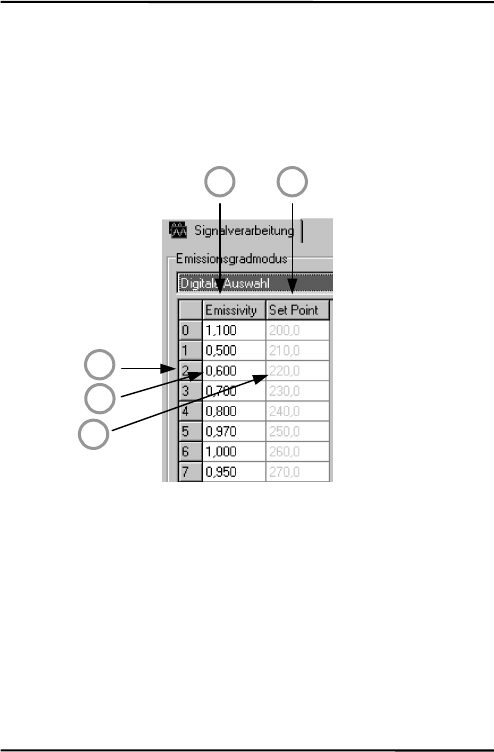
Thereareeightentriespossibleforemissivitysetting(1)andarelated
setpoint(threshold)(2).Tobeabletowriteorreadthesevalues,use
thefollowingcommands:
EP=2setpointerfortableentry,e.g.toline2(3)
RV=0.600settheemissivityvalueforline2to0.600(4)
SV=220.0setthesetpoint(threshold)forline2to220.0(5)
Figure46:TableforEmissivityandSetPoints
Toactivatetheseemissivitysettings,youneedtohavethe3external
inputs(FTC)connected.Accordingtothedigitalcombinationonthe
FTCwires,oneofthetableentrieswillbeactivated,seesection5.4.2
EmissivitySettingviaDigitalSelectiononpage25.
1 2
3
4
5

ProgrammingGuide
72MI
11.4.3PostProcessing
Thefollowingparameterscanbesettodeterminethepostprocessing
mode,seesection6.4PostProcessingonpage38.
P=5peakhold,holdtime:5s
F=12.5valleyhold,holdtime:12.5s
G=10averaging,averagetime(90%):10s
XY=3advancedpeakhold,hysteresis:3K
XY=‐2advancedvalleyhold,hysteresis:2K
AdvancedPeak/ValleyHoldwithAveraging:
C=250threshold:250°C
AA=15averagingtime(90%):15s
11.5DynamicData
Alltemperaturerelatedinformationiscalculated128timesasecond.
Torequestthedynamicdata,followingcommandsareavailable:
?Ttargettemperature
?Iinternaltemperatureofthesensinghead
?XJinternaltemperatureofelectronicshousing
?Qenergyvalueoftheinfra‐redtemperature
?XTtriggersetpoint(active/inactive)fortheFTC3input
Tocheckforresets(e.g.powershutdown)usethecommandXI.
Notice,afteraresettheunitisnewinitialized.
?XIasksfortheresetstatus
!XI0noresetoccurred
!XI1aresetoccurred,newinitializationoftheunit
XI=0setstheresetstatusbackto0

ProgrammingGuide
MI73
11.6DeviceControl
11.6.1OutputfortheTargetTemperature
Thesignaloutputcanbesetto4–20mA,0–20mAormV.Ifcurrent
outputisactivated,theoutputcanprovideapredefinedcurrent:
XO=4outputmodeto4–20mA
O=13.57outputofaconstantcurrentat13.57mA
O=60switchesbacktothetemperaturecontrolledoutput
11.6.2AnalogOutput,Scaling
Accordingtothetemperaturerangeofthemodel,itispossibletoset
amaximumvoltage/currentvalueaccordingtoatemperaturevalue
(e.g.,themaximumcurrent20mAshallrepresent200°C/392°F).The
samesettingispossiblefortheminimumvalue.
H=500themaximumcurrent/voltagevalueissetto500°C
L=0theminimumcurrent/voltagevalueissetto0°C
Remark:Youcannotsetthisvalueforthermocoupleoutput.The
minimumspanbetweenthemaximum/minimumsettingsis20K.
11.6.3AlarmOutput
Thesecondoutputchannelcanbesetindifferentmodes,seesection
5.3.2HeadAmbientTemp./AlarmOutputonpage20.
• Internalsensingheadtemperature
• Alarmoutput
K=7internalsensingheadtemperature
K=4alarmoutputforobjecttemperature,0Vincaseofno
alarm
XS=125.3thresholdsettingto125.3°C(ifU=Cisset)
11.6.4Factorydefaultvalues
Itispossibletoresettheunittothedefaultvalues.

ProgrammingGuide
74MI
XFfactorydefaultvalueswillbeset
11.6.5LockMode
Theaccesstotheunitispossibleviaserialinterface(software)and
viathedirectuserinput(modebuttons,LCDdisplay).Itispossible
tolockthebuttons.Thisallowsaccesstheunitonlyviasoftware.
J=Ldirectuserinputviamodebuttonsdenied
Alternativelytheunitcanbeunlockedbypressingthe<Mode/Up>
buttonssimultaneouslyforthreeseconds.
11.6.6ModeSettingfortheDigitalInputFTC3
ThedigitalinputFTC3(seesection5.4.4TriggerandHoldFunction
onpage28)canbeusedasfollows:
XN=TFTC3astrigger
XN=HFTC3withholdfunction
11.6.7ChangingtheSensingHeadCalibrationData
Ifitisnecessarytoexchangethesensinghead,youmustsetthe
calibrationdataforthenewsensinghead:
XZ=01234567FFFFFFFFaccordingtotheheadcalibrationdata
ForMID/MIC‐modelsthelasteightnumbersarenotusedandmust
besetto„F“likeshownintheexampleabove.ForMIH‐modelsand
specials(likeMTBorG5)allsixteennumbersareused.
11.6.8AmbientBackgroundTemperatureCompensation
Incaseofcompensatingtheambientbackgroundtemperature,the
followingmodesareavailable:
AC=0nocompensation
AC=1compensationwithaconstanttemperaturevalueset
withcommandA.

ProgrammingGuide
MI75
AC=2compensationwithanexternalvoltagesignalatthe
analoginputFTC2(0V–5Vcorrespondstolowend
andhighendoftemperaturerange),currentambient
temperatureisreadablewithcommandA.
Note:ThemodeAC=2doesnotfunctionincaseof
settingthecommandES=D!
Formoreinformationregardingtheambientbackground
temperaturecompensationseesection5.4.3AmbientBackground
Temp.Compensationenpage26.

ProgrammingGuide
76MI
11.7MultipleUnits(RS485MultidropMode)
Upto32unitscanbeconnectedwithinaRS485network,seesection
5.6InstallingofMultipleSensorsviaRS485onpage31.Todirecta
commandtooneunitamongthe32possible,itisnecessaryto
„address“acommand.Therefore,a3‐digitnumberissetpriorthe
command.The3‐digitnumberisdeterminedbetween001and032.
Exception:Broadcastcommand.
Ifacommandistransferred,startingwiththe3‐digitnumber000,all
units(withaddressesfrom001to032)connectedwillgetthis
command–withouttosendananswer.
Note:Aunitwiththeaddress000isasingleunitandnotin
multidropmode.
XA=024willsetaddressto24(unitmustnotbeinmultidropmode)
Changinganaddress:
(e.g.theaddressischangefrom24to17)
commandanswer
„017?E“„017E0.950“
„017XA=024““017XA024”settingofanewaddress
„024?E“„024E0.950“
Exampleforthebroadcastcommand:
commandanswer
“024?E”“024E0.950”
“000E=0.5”willbeexecutedfromallunits,noanswer
“024?E”“024E0.500”
“012?E”“012E0.500”

ProgrammingGuide
MI77
11.8CommandSet
Description Char Format P B S Legal values Factory
default
LCD
Poll parameter ? ?X/?XX * ?T
Set parameter = X/XX=... * E=0.85
Set parameter without
EEPROM storage
# X/XX# * E#0.85
Multidrop addressing 001?E * * answer:
001!E0.95
Error message * *Syntax error
Acknowledge message ! !P010
Burst string format $ * * (3) UTEI
Ambient background
temp. compensation
A nnn.n * * * (1) (6)
Advanced hold with
average
AA nnn.n * * 000.0 – 999 s 000.0 s
Control ambient
background temp.
compensation
AC n * * 0 = head temp.,
1 = via number,
2 = via external
input
0
Advanced hold threshold C nnn.n * * in current
scale(C / F)
300
Currently calculated
emissivity
CE n.nnn *
Current calculation
setpoint / relay function
CS nnn.n * In current scale
(C / F)
Device adjustment gain DG n.nnnn * * 0.8000 1.2000 1.0000
Device adjustment offset DO nnn * * -200 +200 0
Device special DS XXX * z.B. !DSRAY
Emissivity internal (10) E n.nnn * * * 0.100 – 1.100 0.950 E
Error Code EC nnnn * Hex value of
ErrCode
Presel. emissivity pointer
(10)
EP n * * 0 – 7 7

ProgrammingGuide
78MI
Description Char Format P B S Legal values Factory
default
LCD
Source: emissivity /
setpoint for alarm output
ES X * * I=constant
number
(E=0.950)
E=external
analogous input
FTC1
D= E/XS digital
selected FTC1-3
I
Presel. emissivity value EV n.nnn * * 0.100 - 1.100
Valley hold time(4) F nnn.n * * * 0.000 - 998.9 s
(999 = infinite)
000.0 s V
Average time G nnn.n * * * 000.0 – 999 s 000.0 s A
Top of mA/mV range H nnn.n * * * (1) (7) H
Sensor / head ambient I nnn.n * * in current scale
(°C/°F)
Switch panel lock J X * * L=locked
U=unlocked
unlocked
Alarm output control K N * * 0=off
1=on
2=Target.; norm.
open
3=norm. closed
4=Head; normal
open
5=norm. closed
7=sensor / head
ambient
?
Bottom of mA/mV range L nnn.n * * * (1) (8) L
Output voltage O n.nnn * * 0.000 – 5.000
voltage in V
6=controlled by
unit
6
Output current O nn.nn * * 0.00 – 20.00
current in mA
21=over range
60=controlled by
unit
60 L
Peak hold time (4) P nnn.n * * * 000.0 998.9 s
(999 = infinite)
000.0 s P
Power/AD value Q nnnn * *

ProgrammingGuide
MI79
Description Char Format P B S Legal values Factory
default
LCD
Presel. setpoint / relay
function
SV nnn.n (1)
Target temperature T nnn.n * * in current scale
(°C / °F)
Temperature unit U X * * * C / F C U
Poll / Burst mode V X * * P = poll
B = burst
Poll mode
Burst string contents X$ *
Multidrop address XA nnn * * 000 – 032
000 = single unit
unchanged
(preset: 0)
Bottom temperature of
range
XB nnn.n *
Restore factory defaults XF *
Transmission XG n.nnn * * * 0.100 - 1.000 1.000 T
High temperature of
range
XH nnn.n *
Sensor initialization XI n * * * 1 after Reset,
0 if XI = 0
Box temperature XJ nnn.n * * in current
scale(°C / °F)
FTC 3 trigger / hold XN X * * T = trigger
H = hold
T
Analog output mode XO n * * 0 = 0 – 20 mA
4 = 4 – 20 mA
5 = TCJ
6 = TCK
9 = mV
9
Firmware revision XR * e.g. 1.01
Setpoint / relay function
(10)
XS nnn.n * * (1) 250°C
Trigger XT n * * 0 = inactive
1 = active
0
Unit identification XU * e.g. !XUMILT4
Serial number XV * e.g. 98123
Advance hold hysterese
(4)
XY nnn.n * *
Head calibration (9) XZ * *
(1)LT:‐40to600°C(‐40to1112°F)
(2)n=number,X=uppercaseletter

ProgrammingGuide
80MI
(3)$=UTQE
(4)settingaverage/peak/valley/advancedholdcancelsallotherholdmodes
(6)LT:23°C(73°F)
(7)LT:500°C(932°F)
(8)LT:0°C(32°F)
(9)XZ=0123456789ABCDEFsetcommandchecksformat!Firmwarerestartbyunit
(10)E0=1.100,E1=0.500,E2=0.600,E3=0.700,E4=0.800,E5=0.970,E6=1.000,E7=0.950
XS0=200,XS1=210,XS2=220,XS3=230,XS4=240,XS5=250,XS6=260,XS7=270
En/XSnsetviacommandEP=n(n=0…7)
Table2:CommandSet

Appendix
MI81
12Appendix
12.1DeterminationofEmissivity
Emissivityisameasureofanobject’sabilitytoabsorbandemit
infraredenergy.Itcanhaveavaluebetween0and1.0.Forexamplea
mirrorhasanemissivityof<0.1,whiletheso‐called“Blackbody“
reachesanemissivityvalueof1.0.Ifahigherthanactualemissivity
valueisset,theoutputwillreadlow,providedthetarget
temperatureisaboveitsambienttemperature.Forexample,ifyou
haveset0.95andtheactualemissivityis0.9,thetemperaturereading
willbelowerthanthetruetemperature.
Anobject’semissivitycanbedeterminedbyoneofthefollowing
methods:
1.DeterminetheactualtemperatureofthematerialusinganRTD
(PT100),athermocouple,oranyothersuitablecontact
temperaturemethod.Next,measuretheobject’stemperature
andadjustemissivitysettinguntilthecorrecttemperature
valueisreached.Thisisthecorrectemissivityforthemeasured
material.
2.Forrelativelylowtemperatures(upto260°C/500°F)placea
plasticsticker(e.g.XXXRPMACED)ontheobjecttobe
measured.Thisstickershouldbelargeenoughtocoverthe
targetspot.Next,measurethesticker’stemperatureusingan
emissivitysettingof0.95.Finally,measurethetemperatureof
anadjacentareaontheobjectandadjusttheemissivitysetting
untilthesametemperatureisreached.Thisisthecorrect
emissivityforthemeasuredmaterial.
3.Ifpossible,applyflatblackpainttoaportionofthesurfaceof
theobject.Theemissivityofthepaintis0.95.Next,measurethe
temperatureofthepaintedareausinganemissivitysettingof

Appendix
82MI
0.95.Finally,measurethetemperatureofanadjacentareaon
theobjectandadjusttheemissivityuntilthesametemperature
isreached.Thisisthecorrectemissivityforthemeasured
material.

Appendix
MI83
12.2TypicalEmissivityValues
Thefollowingtableprovidesabriefreferenceguidefordetermining
emissivityandcanbeusedwhenoneoftheabovemethodsisnot
practical.Emissivityvaluesshowninthetableareonlyapproximate,
sinceseveralparametersmayaffecttheemissivityofamaterial.
Theseincludethefollowing:
1.Temperature
2.Angleofmeasurement
3.Geometry(plane,concave,convex)
4.Thickness
5.Surfacequality(polished,rough,oxidized,sandblasted)
6.Spectralrangeofmeasurement
7.Transmission(e.g.thinfilmsplastics)
Tooptimizesurfacetemperaturemeasurements,considerthe
followingguidelines:
• Determinetheobjectemissivityusingtheinstrumentwhichis
alsotobeusedforthemeasurements.
• Avoidreflectionsbyshieldingtheobjectfromsurrounding
temperaturesources.
• Forhighertemperatureobjectsuseinstrumentswiththe
shortestwavelengthpossible.
• Fortranslucentmaterialssuchasplasticfoilsorglass,assure
thatthebackgroundisuniformandlowerintemperaturethan
theobject.
• Mountinstrumentperpendiculartosurfaceifpossible.Inall
cases,donotexceedanglesmorethan30°fromincidence.

Appendix
84MI
METALS
Material Emissivity
3.9 µm 5 µm 8 – 14 µm
Aluminum
Unoxidized 0.02-0.2 0.02-0.2 0.02-0.1
Oxidized 0.2-0.4 0.2-0.4 0.2-0.4
Alloy A3003, Oxidized 0.4 0.4 0.3
Roughened 0.1-0.4 0.1-0.4 0.1-0.3
Polished 0.02-0.1 0.02-0.1 0.02-0.1
Brass
Polished 0.01-0.05 0.01-0.05 0.01-0.05
Burnished 0.3 0.3 0.3
Oxidized 0.5 0.5 0.5
Chromium 0.03-0.3 0.03-0.3 0.02-0.2
Copper
Polished 0.03 0.03 0.03
Roughened 0.05-0.15 0.05-0.15 0.05-0.1
Oxidized 0.5-0.8 0.5-0.8 0.4-0.8
Gold 0.01-0.1 0.01-0.1 0.01-0.1
Haynes
Alloy 0.3-0.8 0.3-0.8 0.3-0.8
Inconel
Oxidized 0.6-0.9 0.6-0.9 0.7-0.95
Sandblasted 0.3-0.6 0.3-0.6 0.3-0.6
Electropolished 0.15 0.15 0.15
Iron
Oxidized 0.6-0.9 0.6-0.9 0.5-0.9
Unoxidized 0.05-0.25 0.05-0.25 0.05-0.2
Rusted 0.5-0.8 0.5-0.8 0.5-0.7
Molten — — —
Iron, Cast
Oxidized 0.65-0.95 0.65-0.95 0.6-0.95
Unoxidized 0.25 0.25 0.2
Molten 0.2-0.3 0.2-0.3 0.2-0.3
Iron, Wrought
Dull 0.9 0.9 0.9
Lead

Appendix
MI85
Polished 0.05-0.2 0.05-0.2 0.05-0.1
Rough 0.4 0.4 0.4
Oxidized 0.2-0.7 0.2-0.7 0.2-0.6
Magnesium 0.03-0.15 0.03-0.15 0.02-0.1
Mercury 0.05-0.15 0.05-0.15 0.05-0.15
Molybdenum
Oxidized 0.3-0.7 0.3-0.7 0.2-0.6
Unoxidized 0.1-0.15 0.1-0.15 0.1
Monel (Ni-Cu) 0.1-0.5 0.1-0.5 0.1-0.14
Nickel
Oxidized 0.3-0.6 0.3-0.6 0.2-0.5
Electrolytic 0.1-0.15 0.1-0.15 0.05-0.15
Platinum
Black 0.9 0.9 0.9
Silver 0.02 0.02 0.02
Steel
Cold-Rolled 0.8-0.9 0.8-0.9 0.7-0.9
Ground Sheet 0.5-0.7 0.5-0.7 0.4-0.6
Polished Sheet 0.1 0.1 0.1
Molten 0.1-0.2 0.1-0.2 —
Oxidized 0.7-0.9 0.7-0.9 0.7-0.9
Stainless 0.15-0.8 0.15-0.8 0.1-0.8
Tin (Unoxidized) 0.05 0.05 0.05
Titanium
Polished 0.1-0.3 0.1-0.3 0.05-0.2
Oxidized 0.5-0.7 0.5-0.7 0.5-0.6
Tungsten 0.05-0.5 0.05-0.5 0.03
Polished 0.05-0.25 0.05-0.25 0.03-0.1
Zinc
Oxidized 0.1 0.1 0.1
Polished 0.03 0.03 0.02
Tab.10:TypicalEmissivityValuesforMetals

Appendix
86MI
NON-METALS
Material Emissivity
3.9 µm 5 µm 8 – 14 µm
Asbestos 0.9 0.95
Asphalt 0.95 0.95
Basalt 0.7 0.7
Carbon
Unoxidized 0.8-0.9 0.8-0.9
Graphite 0.7-0.9 0.7-0.8
Carborundum 0.9 0.9
Ceramic 0.8-0.95 0.95
Clay 0.85-0.95 0.95
Concrete 0.9 0.95
Cloth 0.95 0.95
Glass
Plate 0.98 0.85
“Gob” 0.9 —
Gravel 0.95 0.95
Gypsum 0.4-0.97 0.8-0.95
Ice — 0.98
Limestone 0.4-0.98 0.98
Paint (non-al.) — 0.9-0.95
Paper (any color) 0.95 0.95
Plastic, greater than
500 µm (0.02 in) thickness
0.95 0.95
Rubber 0.9 0.95
Sand 0.9 0.9
Snow — 0.9
Soil — 0.9-0.98
Water — 0.93
Wood, Natural 0.9-0.95 0.9-0.95
Tab.11:TypicalEmissivityValuesforNon‐Metals

Index
MI87
Index
Accessories 46
Accuracy 4
Air pressure 12
Air Purge 46
Air Purge Jacket 12
Ambient Temperature 12
Average 60
Control Panel 34, 59
Emissivity 5, 11, 12, 60, 80, 82, 84, 85
Loop impedance 19
Maintenance 60
Mirror 57, 80
Network 32
Noise 13
Optical Resolution 6
Power Supply 60
Repeatability 4
Response Time 4
Sensing Head Exchange 63
Spectral Response 4
Spot Size 14
Temperature Coefficient 5
Temperature Resolution 5
Thermal Shock 5
Transmission 5
Transmission 82
Troubleshooting 60
Valley Hold 60
