Raytheon Anschuetz High Seas GEMRM-10U X-Band Radar Transceiver User Manual Dokument
Raytheon Anschuetz GmbH High Seas Products X-Band Radar Transceiver Dokument
UserManual.wiki
>
Raytheon Anschuetz High Seas
>
GEMRM-10U User Manual
>
Users Manual Part 2
Contents
1.
Users Manual Part 1
2.
Users Manual Part 2
Users Manual Part 2
Navigation menu
Upload a User Manual
Namespaces
Wiki Guide
HTML
PDF
Info
Views
User Manual
Discussion / Help
Navigation
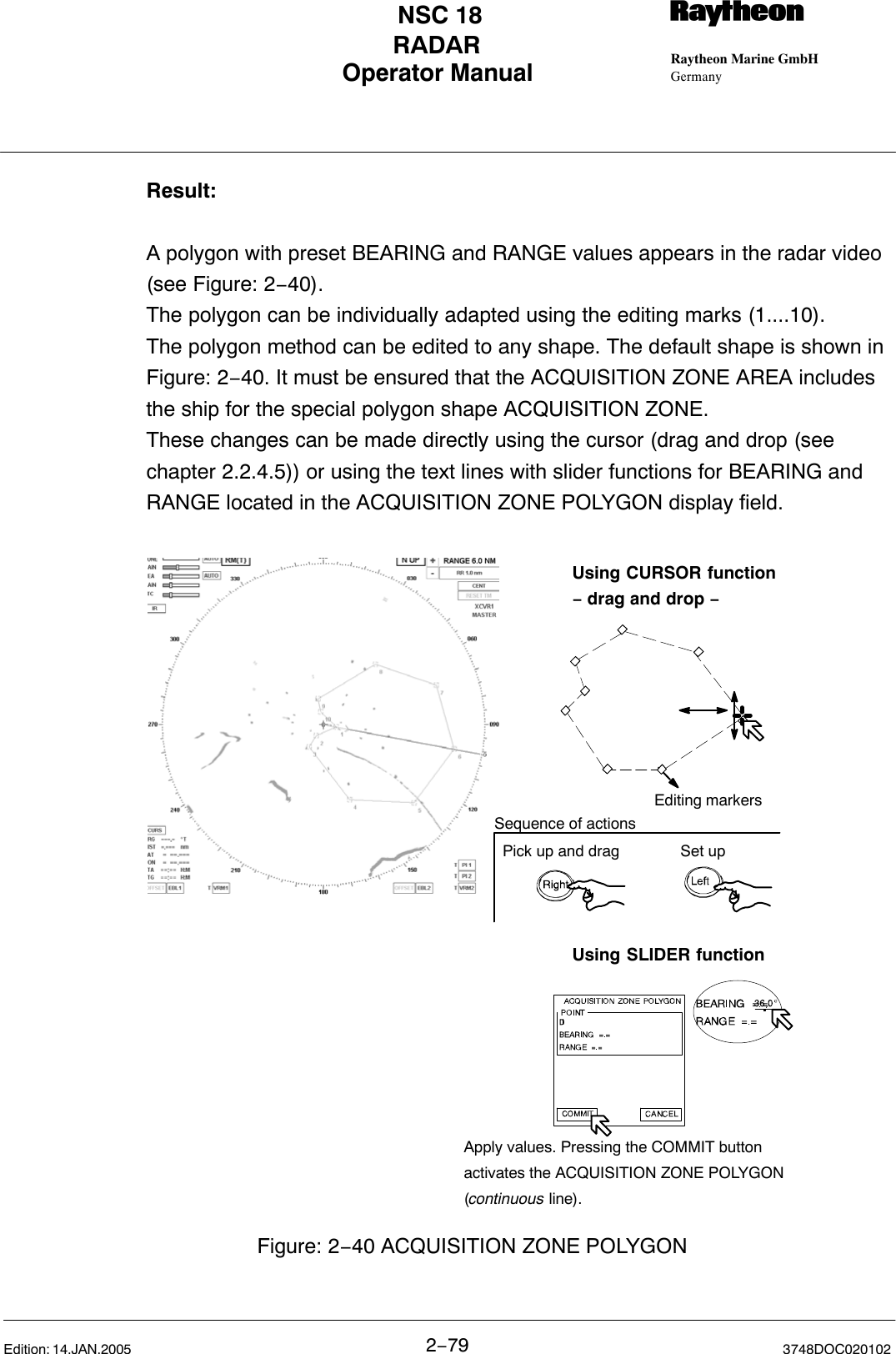
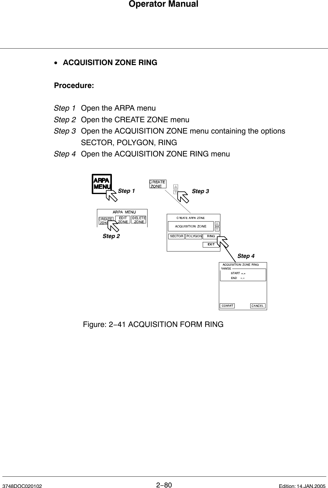
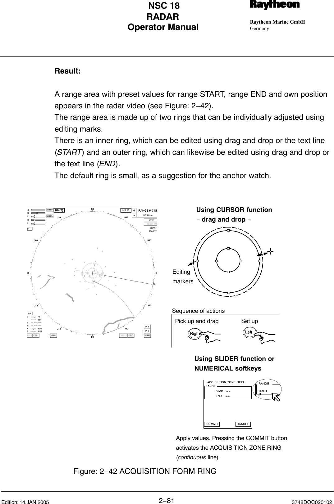
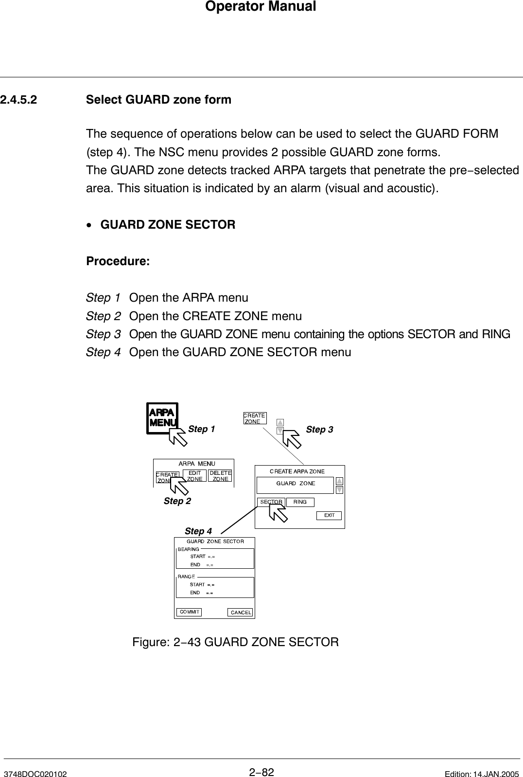
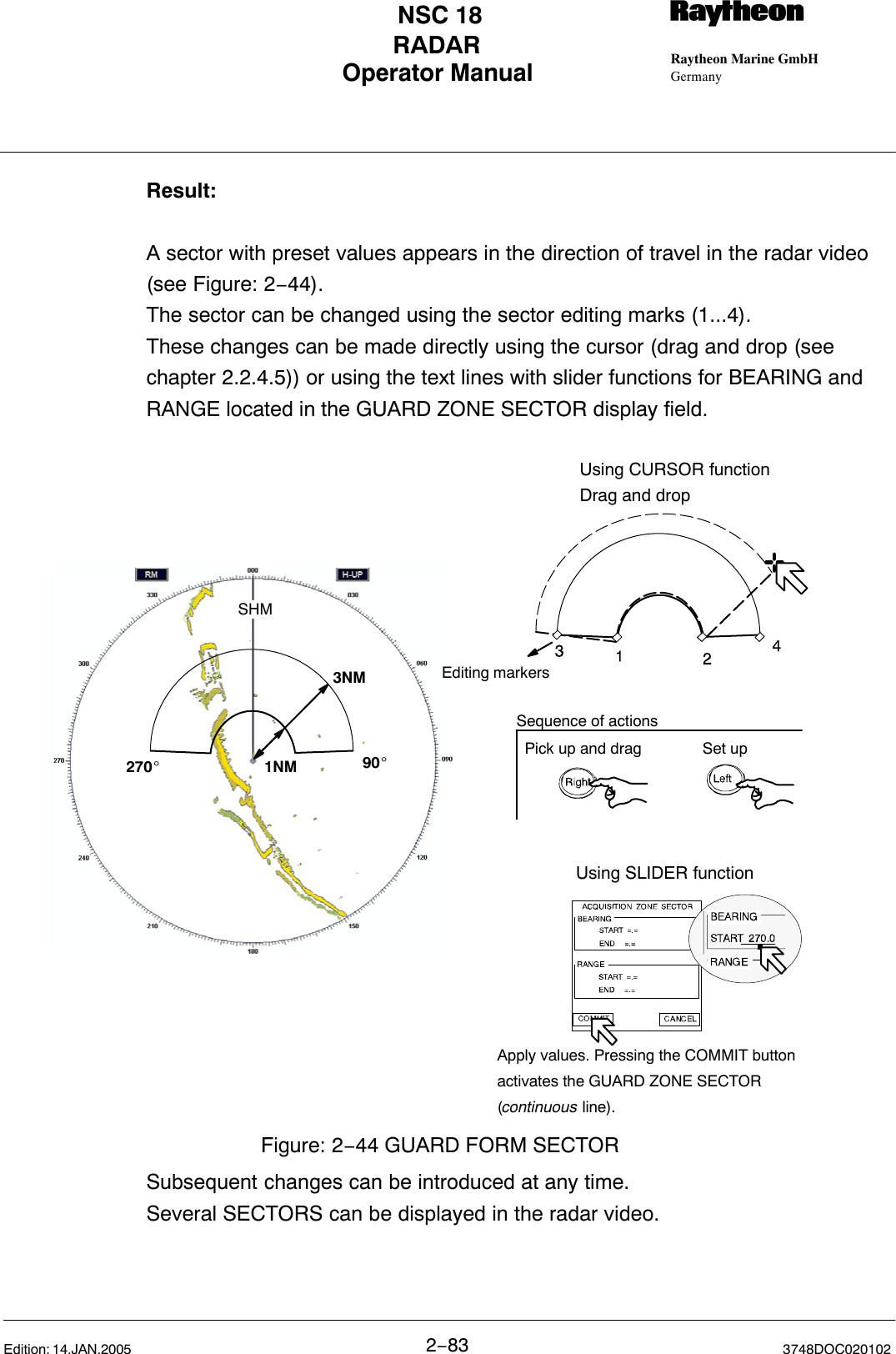
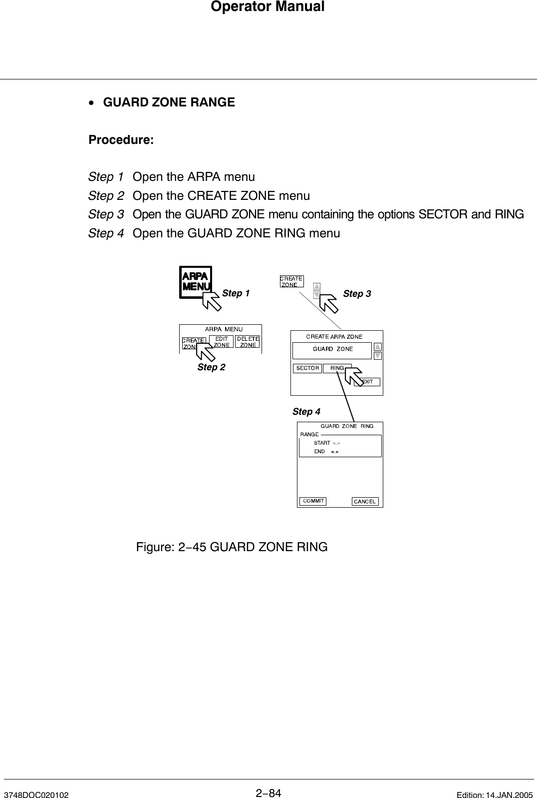
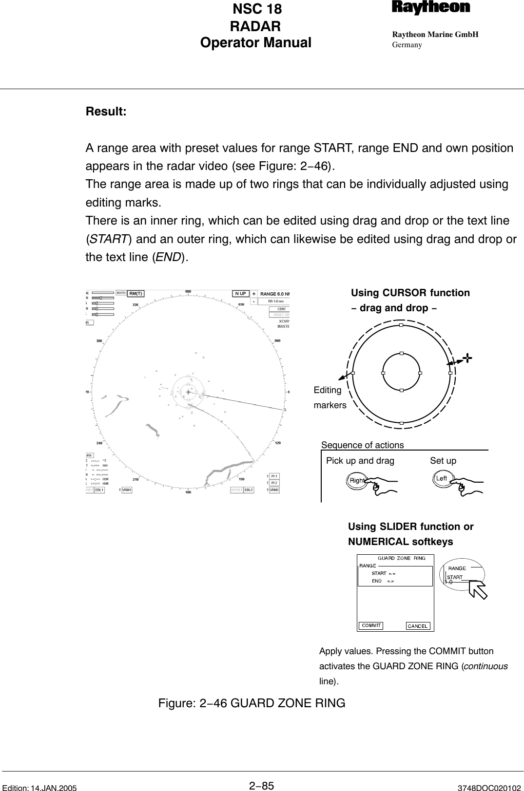
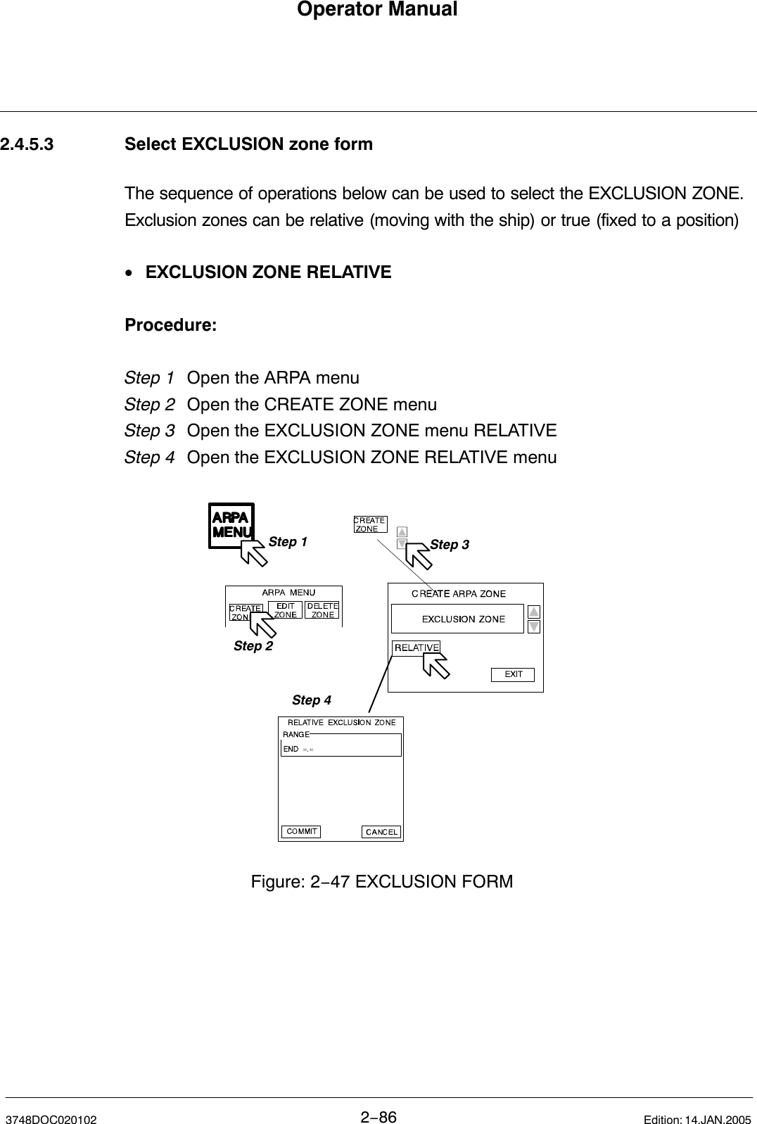
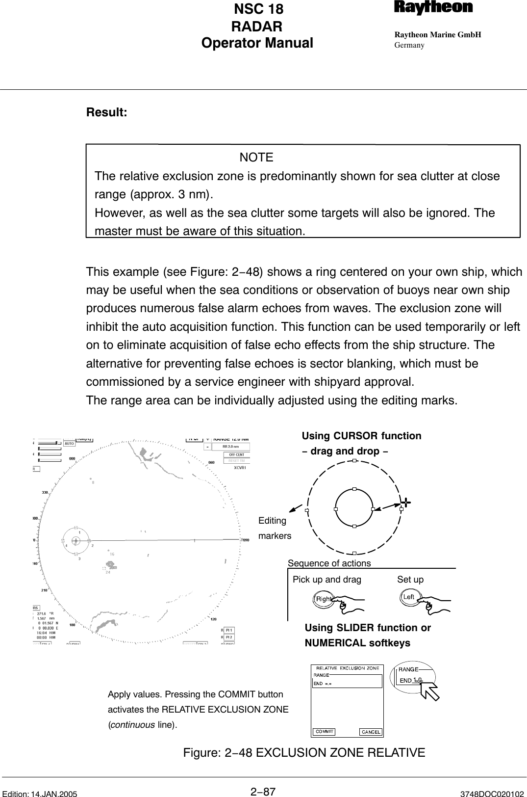
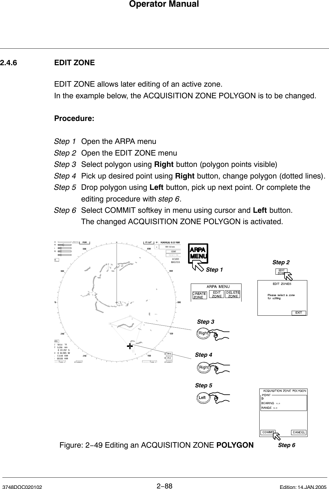
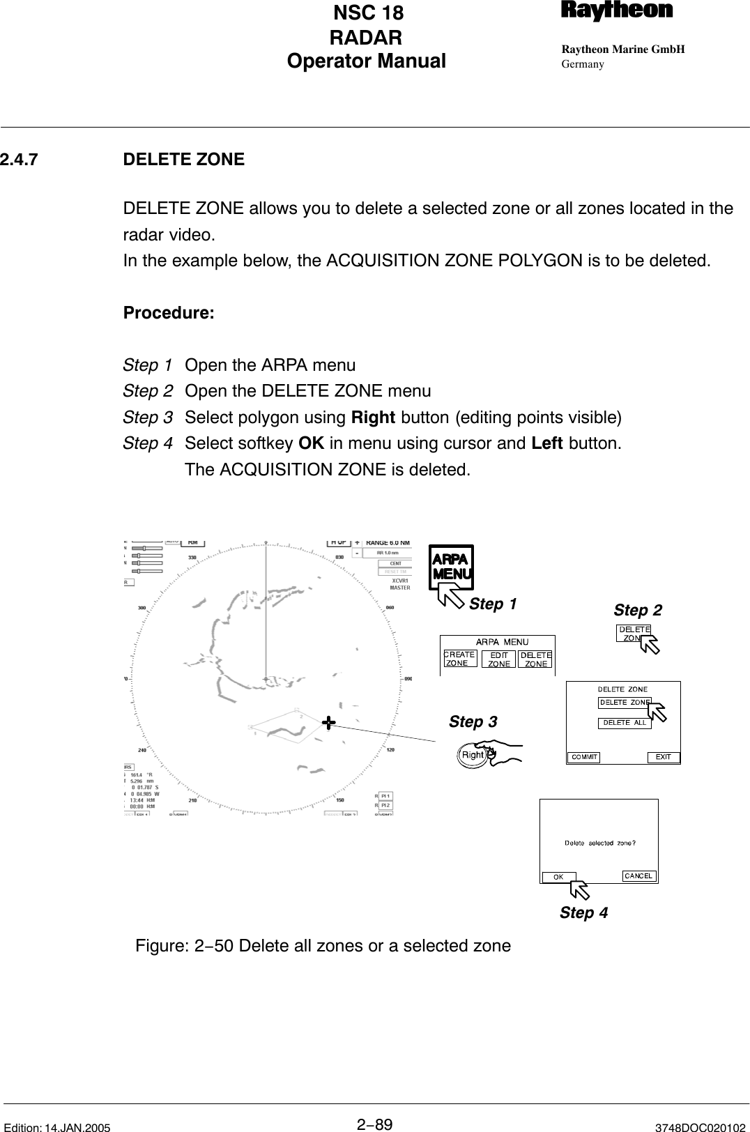
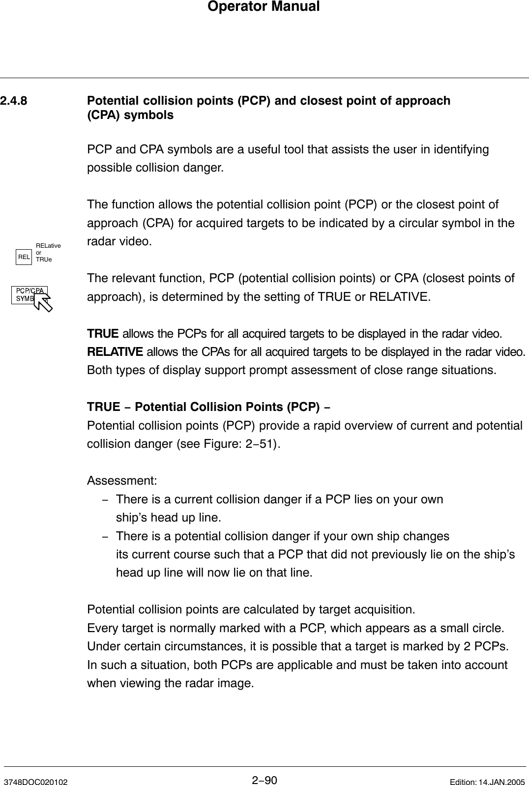
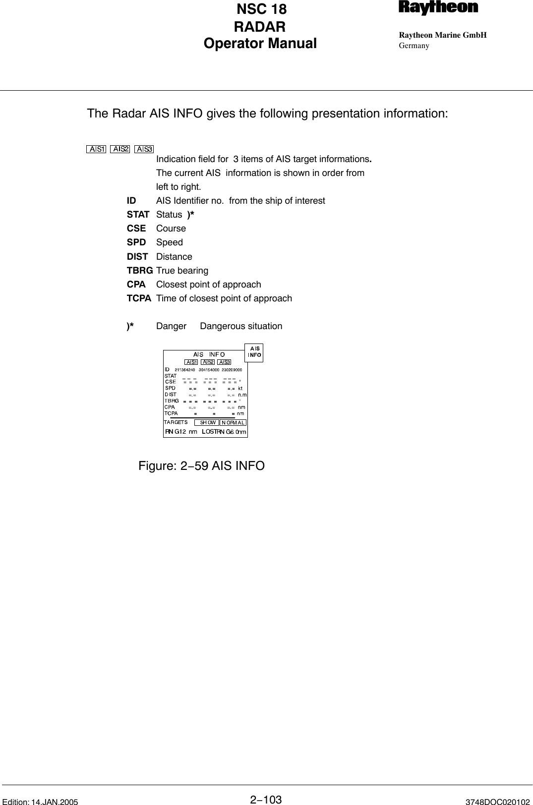
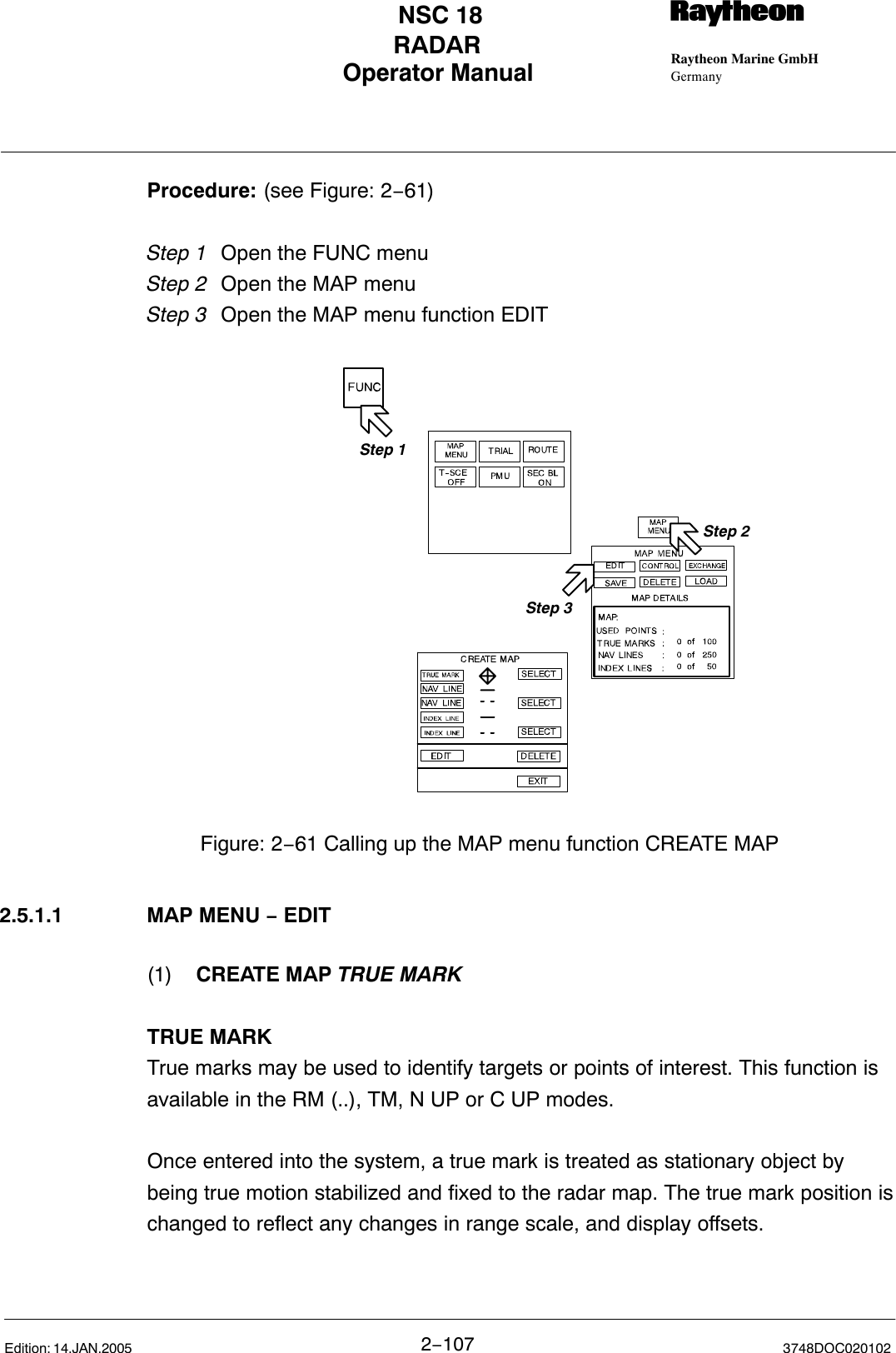
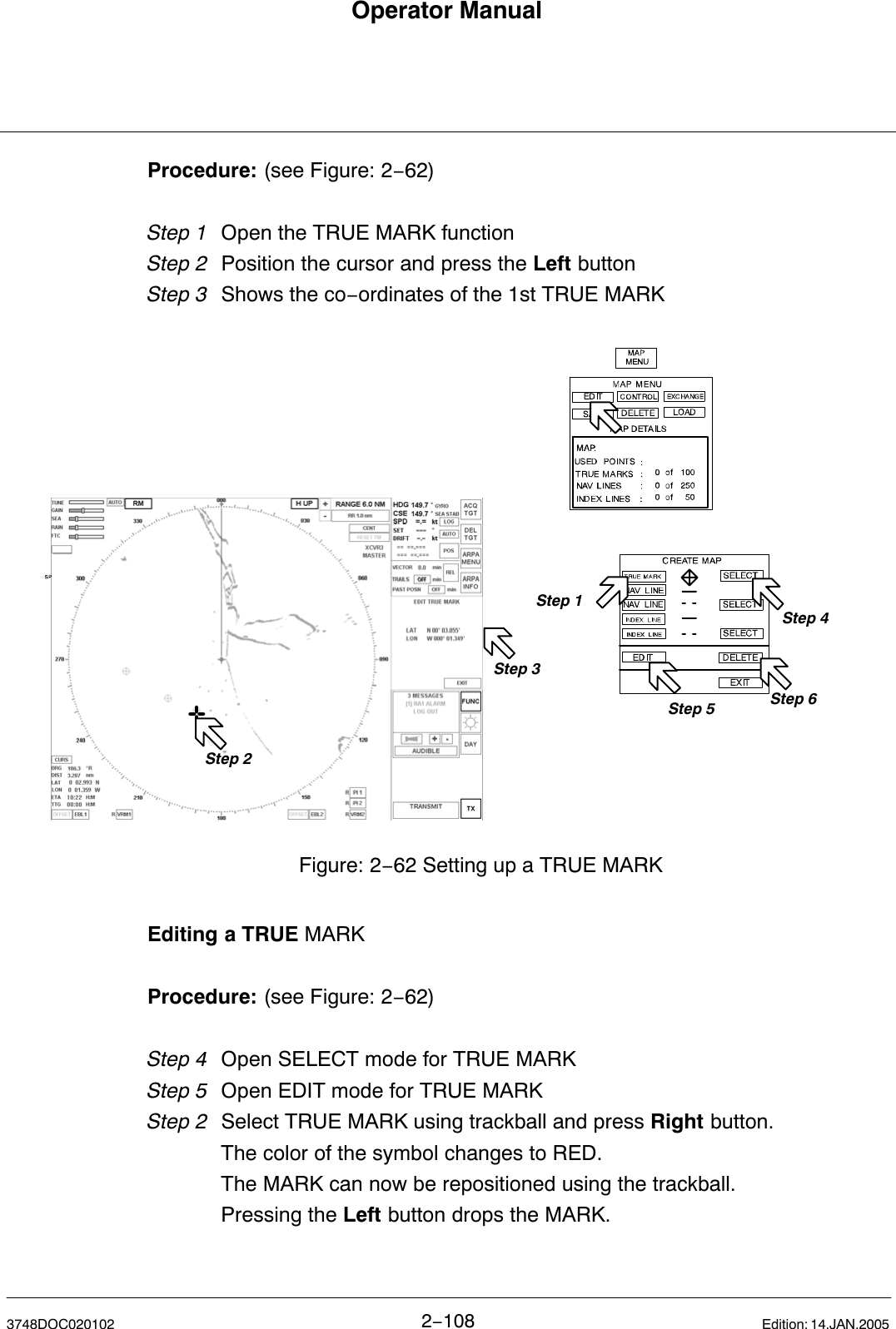
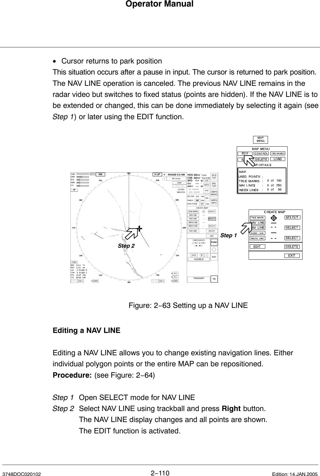
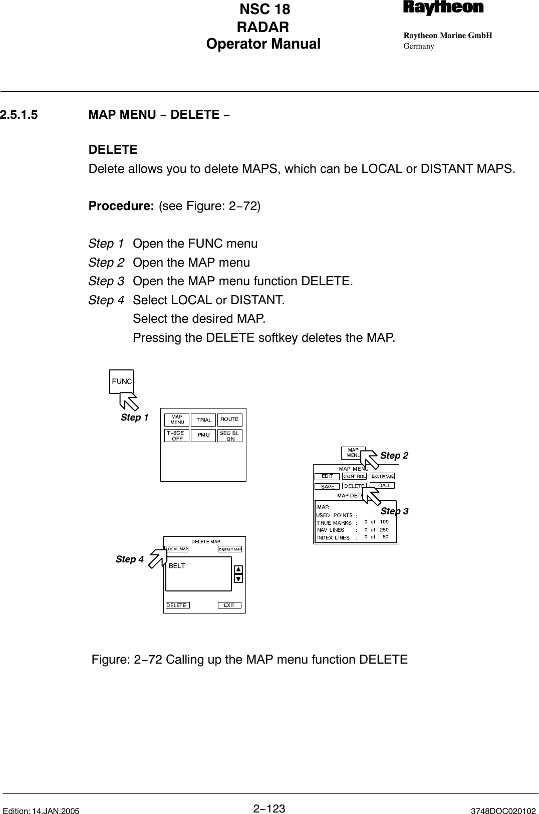
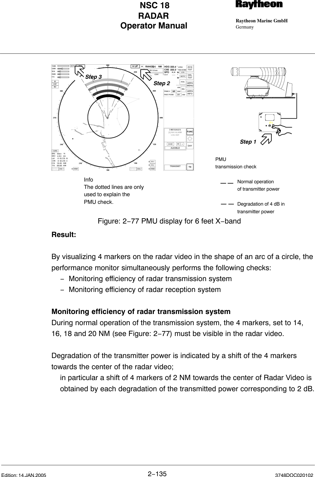

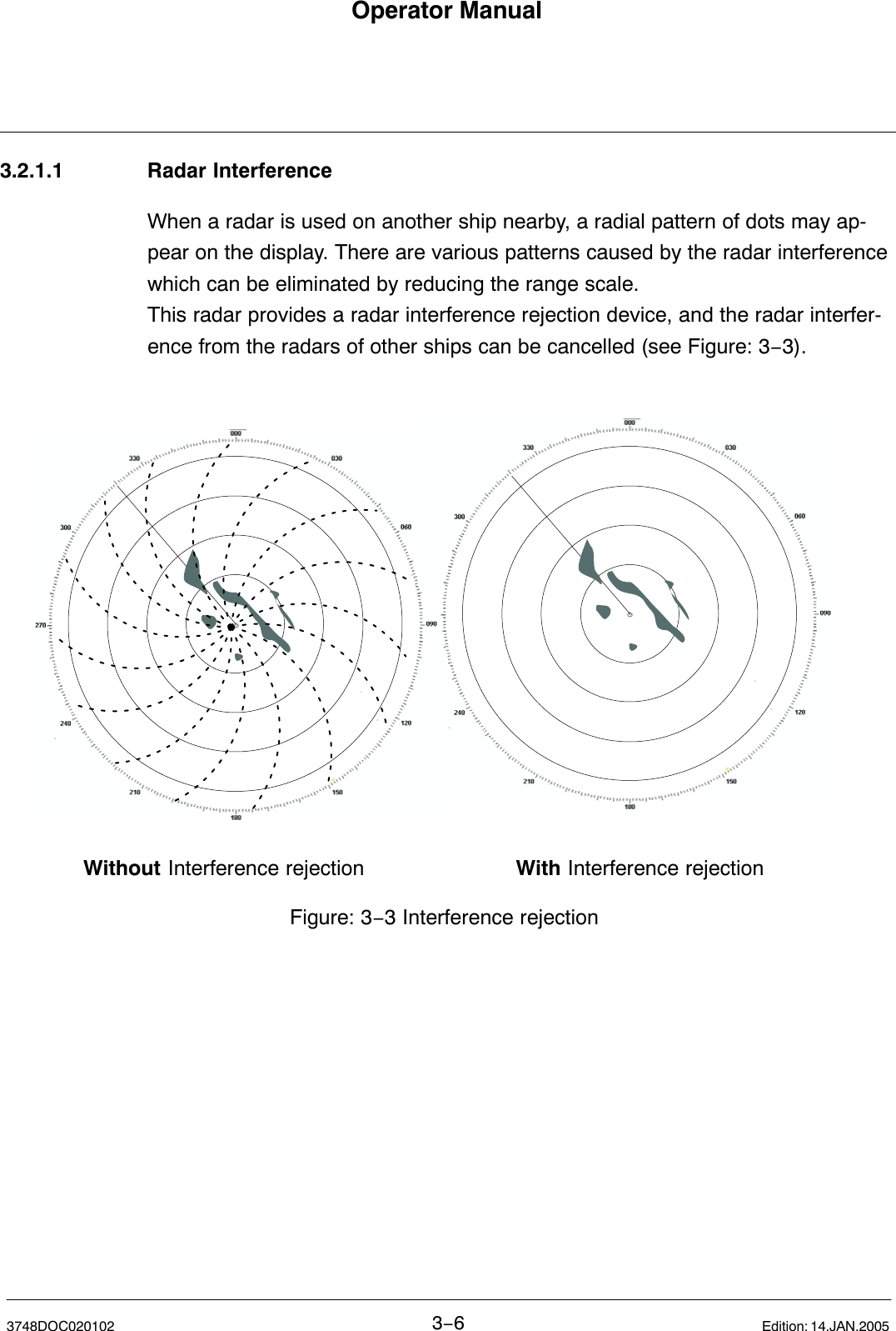
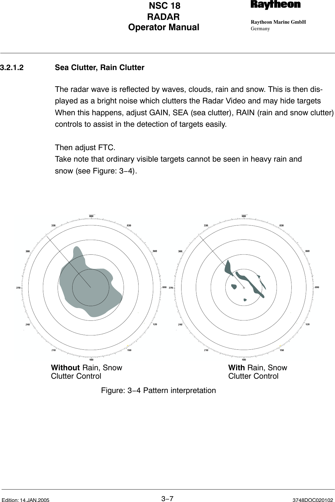
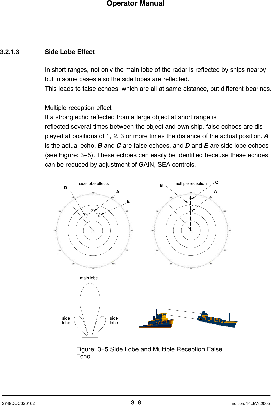
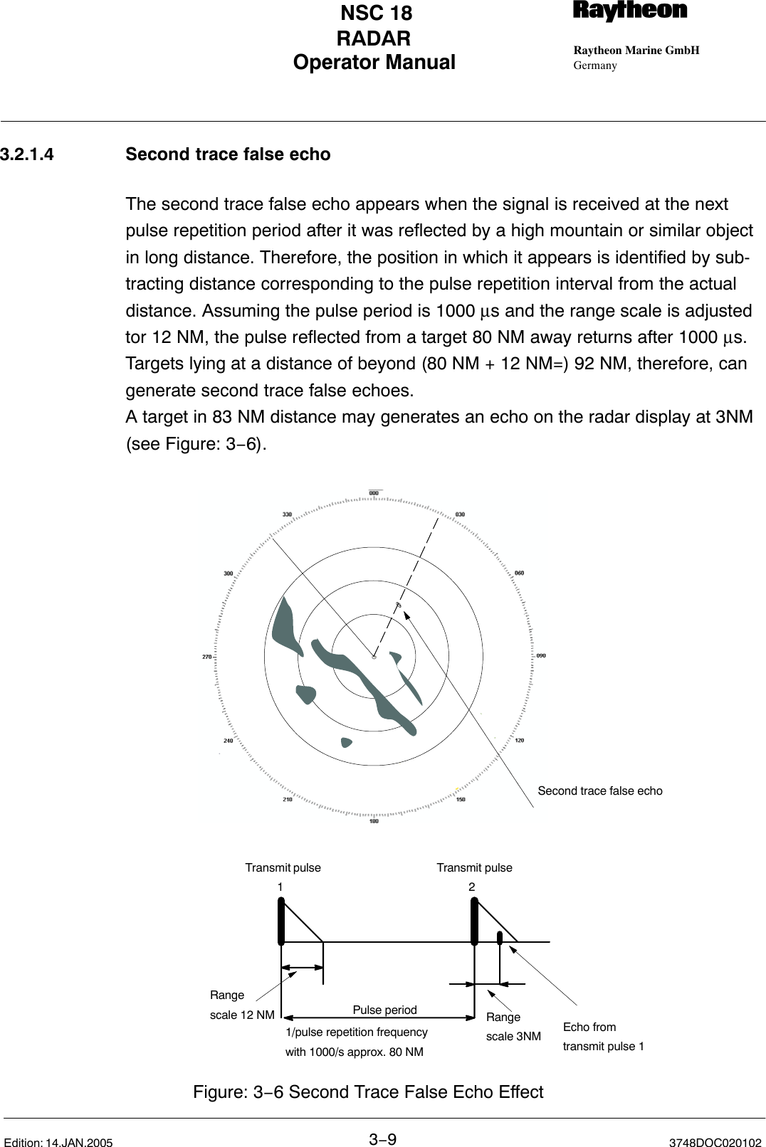
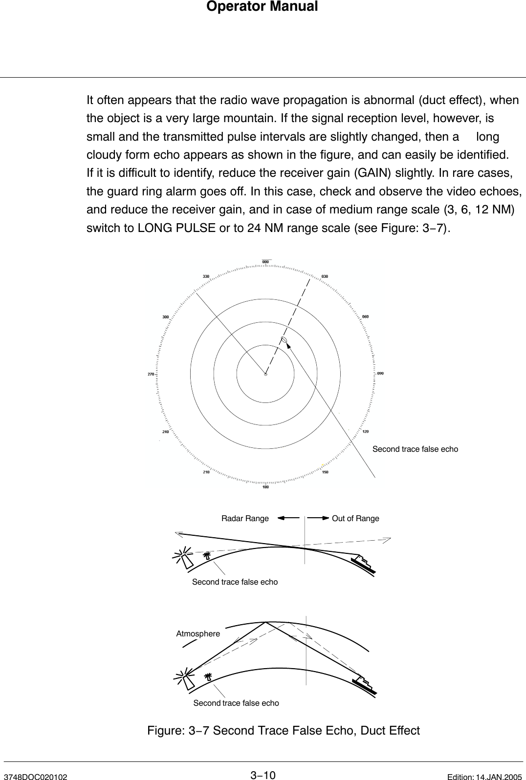
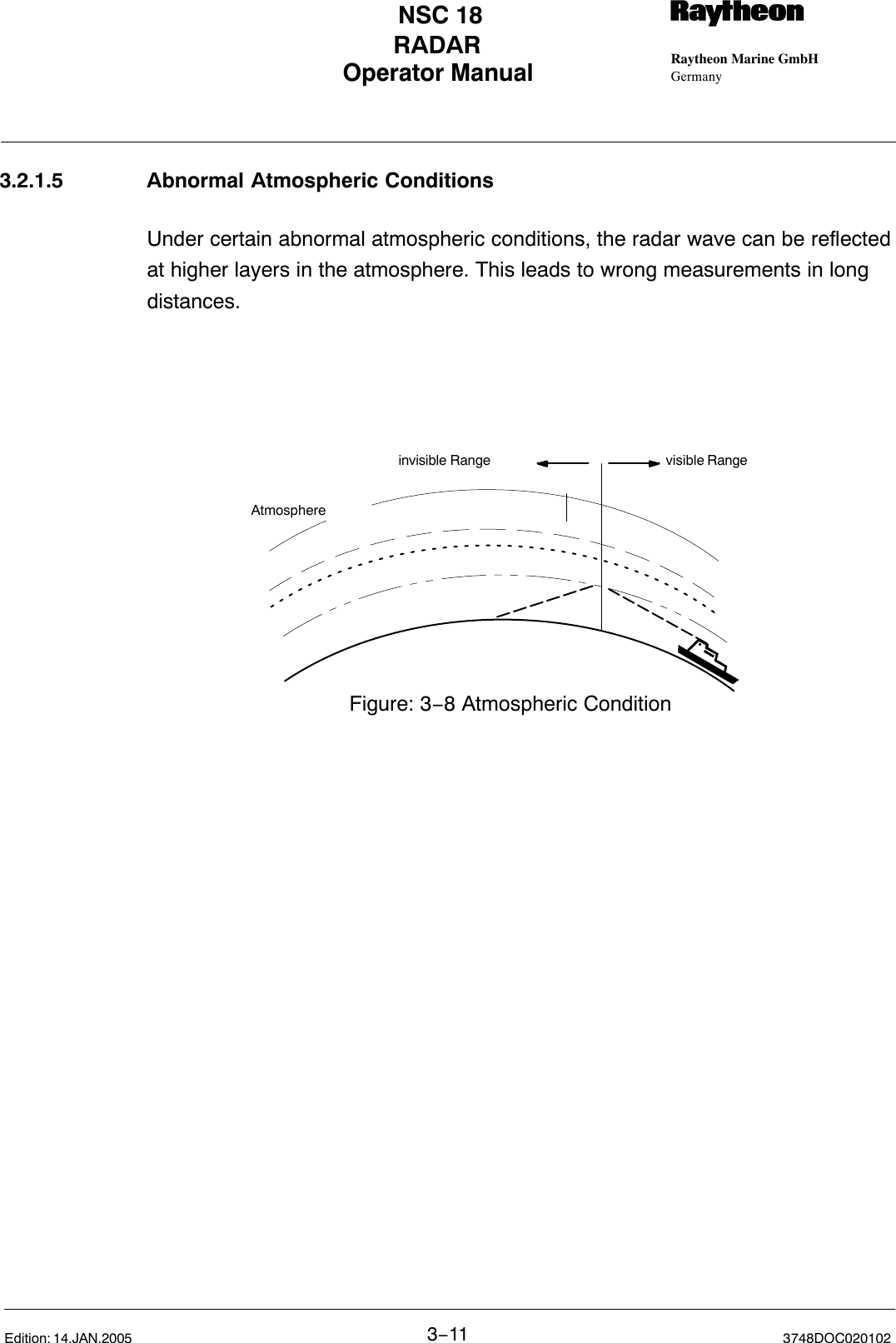
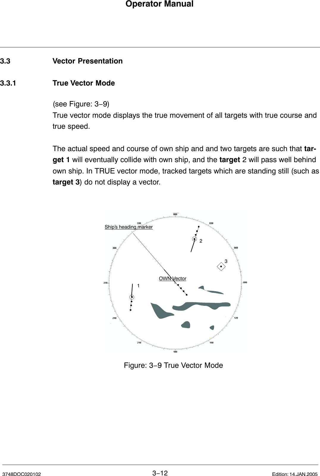
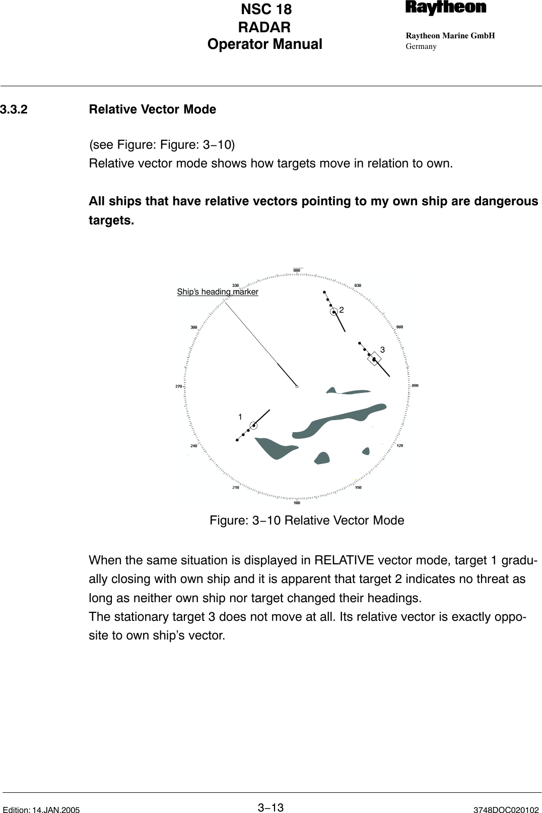
![Operator Manual Raytheon Marine GmbHGermanyRNSC 18RADAR3−53748DOC020102Edition: 14.JAN.20053.2 Radar Pattern InterpretationThe radar displays a chart−like picture (PPI) on TFT under normal conditions.Under certain conditions, however, various false echoes are generated, andsmall targets are hidden by rain, snow or sea waves. To correctly interpret tar-gets and patterns which appears on the TFT requires considerable experience.Compare patterns that appear on the radar image to the actual topography toacquire experience as far as possible.3.2.1 RangeThe detectable range depends on the antenna height and height of targets.Sometimes, however, the radar detectable range is longer due to refraction ofthe wave beam according to weather conditions.The radio wave is obstructed by mountains and hills, forming a shadow behindthese objects.D = 2 (√ H1 + √ H2)H1H2DFigure: 3−2 Detectable RangeD[NM]H[m]Examples:A big ship with 25 m antenna high can detect a 4 m high small ship in up to 14 NM distance.A big ship with 25 m antenna high can detect a 25 m high ship in up to 20 NM.A big ship with 25 m antenna height can detect a 100 m high coast in up to 30NM.](https://usermanual.wiki/Raytheon-Anschuetz-High-Seas/GEMRM-10U.Users-Manual-Part-2/User-Guide-557879-Page-77.png)