Raytheon Anschuetz High Seas MTX5 User Manual Manual
Raytheon Anschuetz GmbH High Seas Products Manual
Manual

Pathfinder
Radar
Scanners
Owner’s
Handbook
Document number: 81154_2
Date: 14th May 1999
154_2cvr.p65 13/05/99, 13:171

154_2cvr.p65 13/05/99, 13:172
Pathfinder Radar Scanners
Owners Handbook
May 1999
SAFETY NOTICES
This radar equipment must be installed and operated in accordance with the
instructions contained in this manual. Failure to do so can result in personal
injury and/or navigational inaccuracies. In particular:
1. HIGH VOLTAGE. The scanner unit contains high voltages. Adjustments
require specialised service procedures and tools only available to qualified
service technicians – there are no user serviceable parts or adjustments. The
operator should never remove the scanner unit cover or attempt to service the
equipment.
2. ELECTROMAGNETIC ENERGY. The radar scanner transmits
electromagnetic energy. It is important that the radar is turned off whenever
personnel are required to come close to the scanner to perform work on the
scanner assembly or associated equipment.
It is recommended that the radar scanner is mounted out of range of personnel
(above head height).
Do not look directly at the antenna at close range as your eyes are the most
sensitive part of the body to electromagnetic energy.
When properly installed and operated, the use of this radar will conform to the
requirements of ANSI/IEEE C95.1-1992 Standard for Safety Levels with
Respect to Human Exposure to Radio Frequency Electromagnetic Fields, 3 Hz
to 300 GHz and NRPB, Board Statement on Restrictions on Human Exposure
to Static and Time Varying Electromagnetic Fields and Radiation, Doc NRPB,
No. 5 (1993).
3. NAVIGATION AID. This radar unit is only an aid to navigation. Its
accuracy can be affected by many factors, including equipment failure or
defects, environmental conditions, and improper handling or use. It is the user’s
responsibility to exercise common prudence and navigational judgements.
This radar unit should not be relied upon as a substitute for such prudence and
judgement.
154_2saf.p65 13/05/99, 13:171

Pathfinder Radar Scanners
RAYTHEON MARINE products are supported by a network of Authorized
Service Representatives. For information on Raytheon products and services,
contact either of the following:
UNITED STATES Raytheon Marine Company
676 Island Pond Road
Manchester, NH 03109-5420
Telephone: (603) 647-7530
800 539-5539
Fax: (603) 634-4756
EUROPE Raytheon Marine Limited
Anchorage Park
Portsmouth
Hampshire PO3 5TD
England
Telephone: 01705 693611
Fax: 01705 694642
Copyright © Raytheon Marine Company 1999
The technical and graphical information contained in this handbook, to the best
of our knowledge, was correct as it went to press. However, the Raytheon
policy of continuous improvement and updating may change product
specifications without prior notice. As a result, unavoidable differences
between the product and handbook may occur from time to time, for which
liability cannot be accepted by Raytheon.
Raytheon is a registered trademark of Raytheon Company.
SeaTalk is a registered trademark of Raytheon Marine Europe Limited.
HSB is a trademark of Raytheon Marine Company.
Pathfinder is a trademark of Raytheon Marine Company.
This product contains technology provided under license by Acorn Group plc.
The copyright of this intellectual property is acknowledged by Raytheon
Marine Company, as are Acorn’s trademarks and patents. Acorn’s world wide
web address is http://www.acorn.com.
154_2saf.p65 13/05/99, 13:172

Preface iii
Preface
This handbook describes the following Pathfinder radar scanners from
Raytheon:
2D 18" 2 kW Radome Scanner
4D 24" 4 kW Radome Scanner
5S 48" 4 kW Open Array Scanner
CAUTION
The 5S 48" Open Array Scanner must not be used with the SL70 or
Autohelm 7” LCD Display Unit. This may result in damage to the display
due to the high power requirements of the open array scanner.
The handbook contains very important information on the installation and
operation of your new equipment. In order to obtain the best results in operation
and performance, please read this handbook thoroughly.
Raytheon’s Product Support representatives or your local dealer will be
available to answer any questions you may have.
Warranty
To register your Pathfinder Radar Scanner ownership, please take a few
minutes to fill out the warranty registration card found at the end of this
handbook. It is very important that you complete the owner information and
return the card to the factory in order to receive full warranty benefits.
EMC Conformance
All Raytheon equipment and accessories are designed to the best industry
standards for use in the leisure marine environment.
Their design and manufacture conforms to the appropriate Electromagnetic
Compatibility (EMC) standards, but correct installation configuration is
essential to maintain EMC performance.
Note: Then 5S 48” Open Array Scanner has NOT been tested with the SL70 or
Autohelm 7” LCD Display Unit for EMC conformance.
154_2pre.p65 13/05/99, 13:173

iv Pathfinder Radar Scanners
154_2pre.p65 13/05/99, 13:174

Contents v
Contents
Chapter 1: Overview ............................................................................ 1
1.1 Introduction ................................................................................. 1
EMC installation guidelines ......................................................... 2
1.2 Unpacking and inspecting the components .................................... 3
Radome scanners ................................................................... 3
Open array scanners ............................................................... 4
1.3 Selecting the scanner unit site........................................................ 5
Mounting surface: sailboats .................................................... 8
Mounting surface: power boats ............................................... 9
Setting the radiation plane ....................................................... 9
1.4 Cable runs...................................................................................10
Rejoining Cables ...................................................................10
Inter-unit cable ...........................................................................11
Radome scanner cable ...........................................................11
Open array scanner cable .......................................................12
Power cable - radome scanners ....................................................13
Power cable - open array scanners ...............................................15
12 V systems .........................................................................15
24 V and 32 V systems ..........................................................16
Chapter 2: Installing the Scanner ...................................................... 17
2.1 Radome scanner .........................................................................17
Securing the radome scanner to the mounting surface ...................17
Connecting the radome scanner inter-unit cable ...........................18
2.2 Open array scanner ....................................................................21
Securing the pedestal to the mounting platform ............................21
Connecting the open array scanner inter-unit cable .......................23
Fitting the open array to the pedestal ............................................26
154_2con.p65 13/05/99, 13:175

vi Pathfinder Radar Scanners
2.3 System connections ...................................................................27
DC power connection .................................................................27
Scanner connection ....................................................................28
Display unit connection ..............................................................29
Chapter 3:System Tests and Post Installation Alignment ................ 31
System check .............................................................................31
Set up, alignment and timing checks ............................................31
Appendix A: Specification ................................................................. 33
2D 18" Radome Scanner Unit .....................................................33
4D 24" Radome Scanner Unit .....................................................34
..................................................................................................35
5S 48" Open Array Scanner Unit .................................................35
Index ................................................................................................... 37
154_2con.p65 13/05/99, 13:176
Chapter 1: Overview 1
Chapter 1: Overview
1.1 Introduction
This handbook provides instructions to assist you in the installation and set up
of the following radar scanners:
18" Radome Scanner
24" Radome Scanner
48" Open Array Scanner
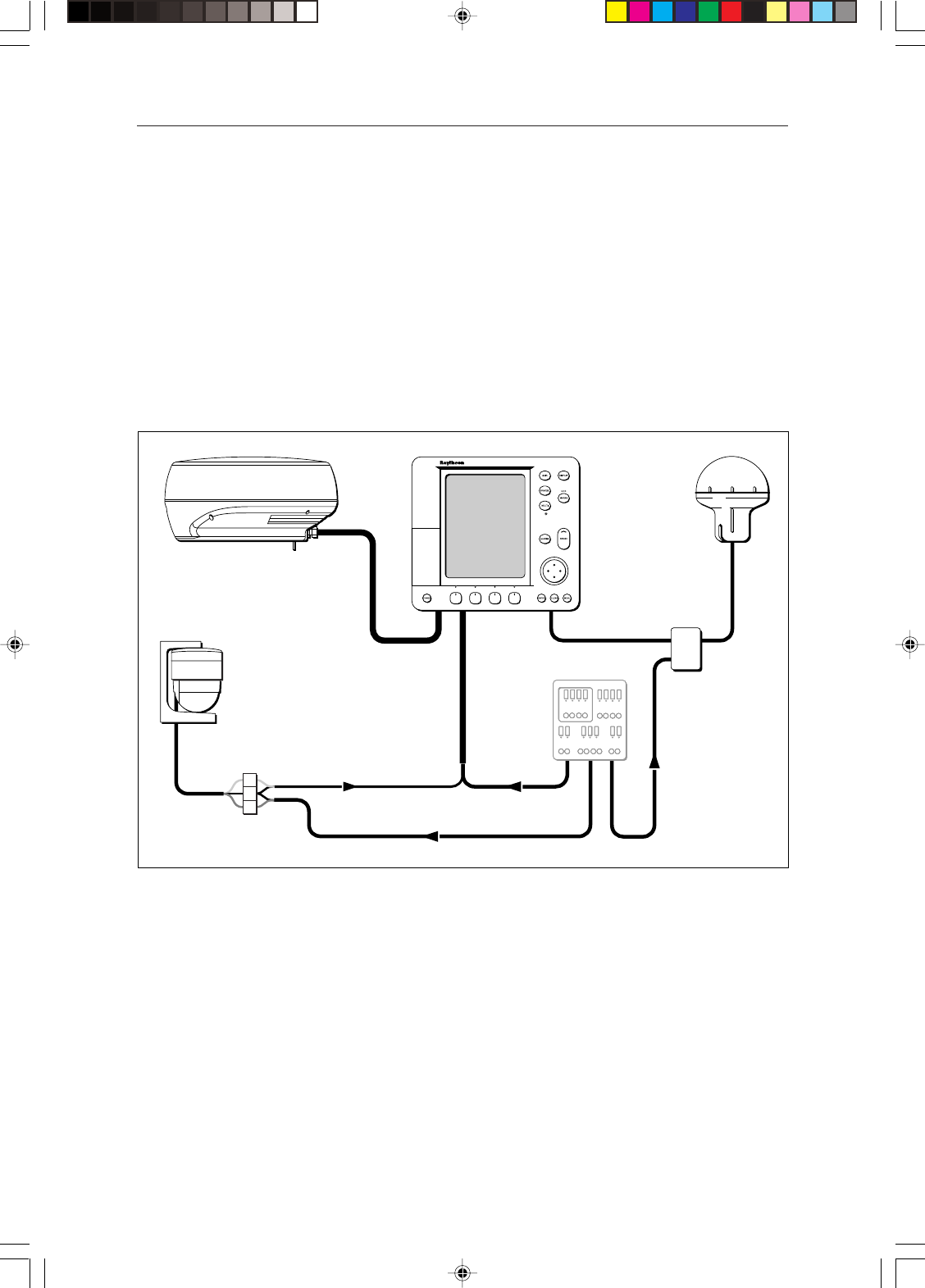
A typical Pathfinder Radar system is illustrated below.
NMEA
SeaTalk
Display Unit
Distribution Panel
D4288-2
Scanner
12/24V Supply
12V Supply 12V Supply
Junction
Box
GPS
Compass
CAUTION
Do not use the 48" Open Array Scanner with an SL70 or Autohelm 7”
display unit. Failure to observe this may result in permanent damage to
these display units.
This handbook is divided into three chapters as follows:
Chapter One provides an overview of the scanner installation. It includes
sections on Unpacking and Inspecting the Components, Selecting the Scanner
Site and a description of the Cable Runs.
Chapter Two provides detailed instructions on how to mount and connect each
type of scanner.
Chapter Three provides instructions on how to perform the system checks,
alignment and adjustments.
154_2c1.p65 13/05/99, 13:171
2Pathfinder Radar Scanners
EMC installation guidelines
All Raytheon equipment and accessories are designed to the best industry
standards for use in the leisure marine environment.
Their design and manufacture conforms to the appropriate Electromagnetic
Compatibility (EMC) standards, but correct installation configuration is
essential to maintain EMC performance and CE compliance. Although every
effort has been taken to ensure that they will perform under all conditions, it is
important to understand what factors could affect the operation of the product.
To avoid the risk of operating problems, all Raytheon equipment, and cables
connected to it, should be installed as follows:
• Ensuring you follow the installation instructions in Chapter 2, particularly
with reference to earthing details.
• With at least 1 m (3 ft) from any equipment transmitting or cables carrying
radio signals e.g. VHF radios, cables and antennas. In the case of SSB radios,
the distance should be increased to 2 m (7 ft).
• Avoiding the beam from another radar scanner. A radar beam can normally
be assumed to spread 20 degrees above and below the radiating element.
• The equipment should be supplied from a different battery than the one used
for engine start. Voltage drops below 10.7 V in the power supply to our
products can cause the equipment to reset. This will not damage the
equipment, but will cause the loss of some information and can change the
mode of operation.
• Genuine Raytheon cables must be used at all times. Cutting and rejoining
these cables can degrade EMC performance and must therefore be avoided
unless specifically detailed in this handbook.
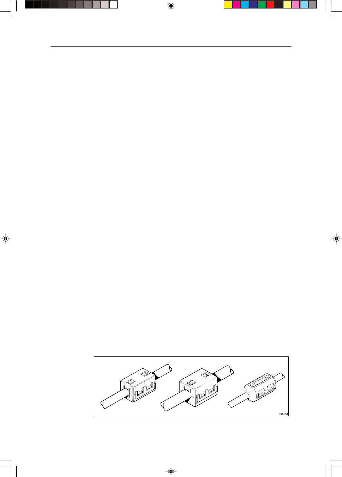
• If a suppression ferrite is attached to a cable, this ferrite must not be removed.
If the ferrite has to be removed during installation it must be reassembled in
the same position. Section 2.1 Installing the Radome Scanner includes
instructions on fitting a ferrite.
The following illustration shows a typical range of suppression ferrites fitted to
Raytheon equipment.
154_2c1.p65 13/05/99, 13:172

Chapter 1: Overview 3
If your Raytheon equipment is going to be connected to other equipment using
a cable not supplied by Raytheon, a suppression ferrite MUST always be fitted
to the cable close to the Raytheon unit.
1.2 Unpacking and inspecting the components
Unpack your system carefully, to prevent damage to the equipment. It is good
practice to save the carton and packing for future use, in case you need to return
the unit for service.
Check that you have all the correct system components. These depend on your
system package, as detailed in the following tables.
Radome scanners
ItemItem
ItemItem
Item Part No.Part No.
Part No.Part No.
Part No. SuppliedSupplied
SuppliedSupplied
Supplied OptionOption
OptionOption
Option
with:with:
with:with:
with: for:for:
for:for:
for:
Radome ScannersRadome Scanners
Radome ScannersRadome Scanners
Radome Scanners
2D 18" 2 kW Radome Scanner M92650 US Version -
2DE 18" 2 kW Radome Scanner M92650E European Version -
4D 24" 4 kW Radome Scanner M92652 - -
Radome Scanner Accessories Radome Scanner Accessories
Radome Scanner Accessories Radome Scanner Accessories
Radome Scanner Accessories (2D & 4D Variants)
Inter-unit cable 15 m heavy M92668 4D -
Inter-unit cable 25 m heavy M92669 - Both
Inter-unit cable 10 m light M92692 2D (US version) -
Inter-unit cable 15 m light M92720 2D (Europe version) -
Extension cable 5 m M92699 - Both
Extension cable 10 m M92700 - Both
Mast Mount 18" Scanner M92722 - 2D
Mast Mount 24" Scanner M92698 - 4D
Radar Interface adapter M92721 - 2D
To fit radome to M88390 type 18" mast mount
Radome mounting interface plate M92731 - 2D
Supplied with HSB Series Display UnitSupplied with HSB Series Display Unit
Supplied with HSB Series Display UnitSupplied with HSB Series Display Unit
Supplied with HSB Series Display Unit
Ferrite Clamp R55007 - Both
154_2c1.p65 13/05/99, 13:173

4Pathfinder Radar Scanners
Open array scanners
ItemItem
ItemItem
Item Part No.Part No.
Part No.Part No.
Part No. SuppliedSupplied
SuppliedSupplied
Supplied OptionOption
OptionOption
Option
with:with:
with:with:
with: for:for:
for:for:
for:
5S 4 kW Scanner Pedestal M92654 5S -
48" Open Array M92693 5S -
Inter-unit cable 5 m heavy E55017 - 5S
Inter-unit cable 15 m heavy M92728 - 5S
Inter-unit cable 25 m heavy M92706 - 5S (24/32V
system only)
Open Array Scanner Accessories Open Array Scanner Accessories
Open Array Scanner Accessories Open Array Scanner Accessories
Open Array Scanner Accessories (5S Variant) - 24/32V systems only
Extension cable 5 m M92699 - 5S
Extension cable 10 m M92700 - 5S
Cable kit: 5 m +10 m extension - 5S
154_2c1.p65 13/05/99, 13:174
Chapter 1: Overview 5
1.3 Selecting the scanner unit site
This section provides information that affects the possible locations of the
scanner, and its position relative to the display unit and to the power supply.
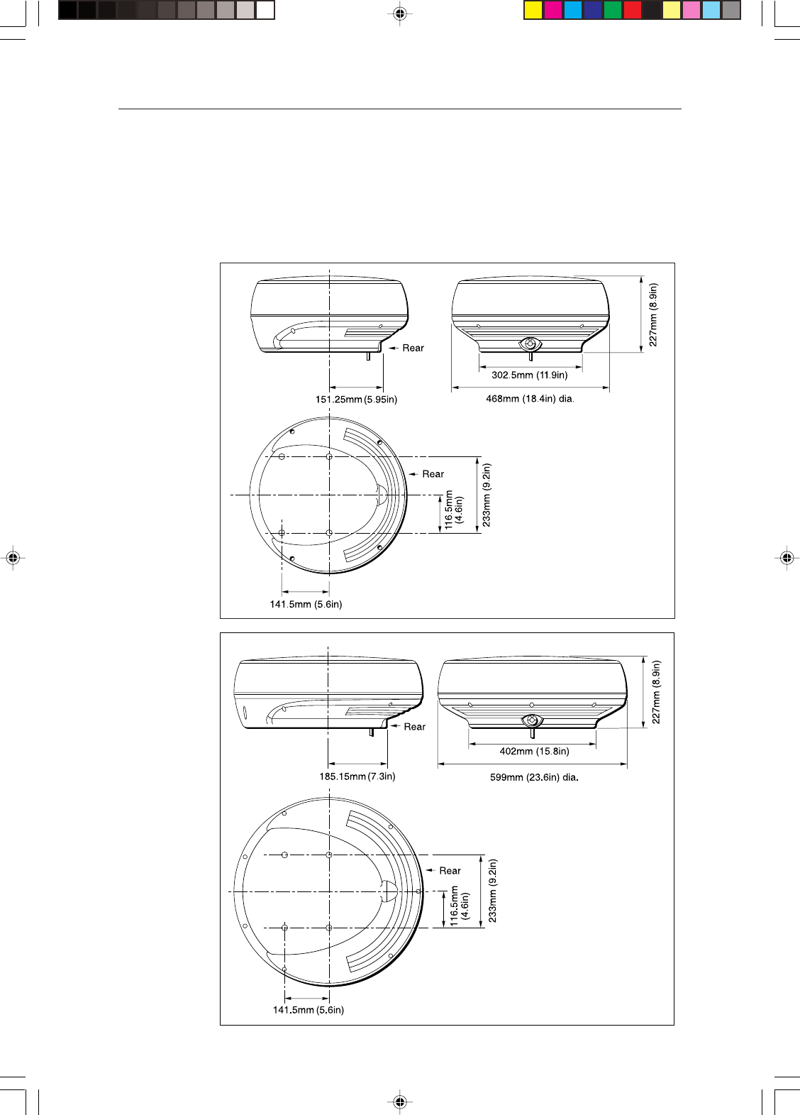
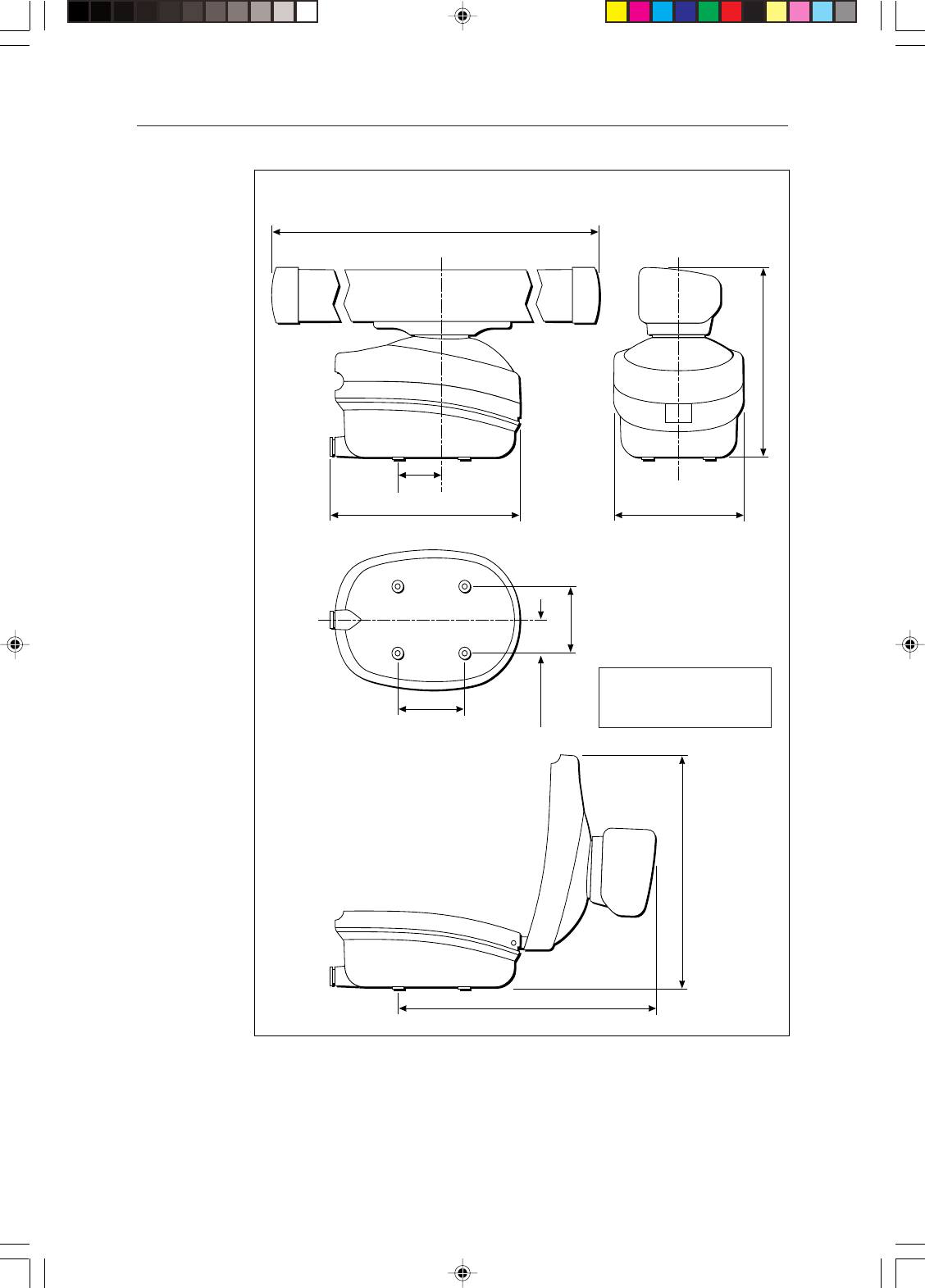
The dimensions of the each scanner unit are shown in the following diagrams.
D3224_3
Weight: 6.5 kg (14.3lbs)
Compass Safe Distance: 1m (33")
18" Radome Scanner
D3228_4
Weight: 7.5 kg (16.5lbs)
Compass Safe Distance: 1m (33")
24" Radome Scanner
154_2c1.p65 13/05/99, 13:175
6Pathfinder Radar Scanners
Centre of rotation Centre of rotation
1306 mm (51.4 in)
100 mm
(4 in)
427 mm (16.8 in) 296 mm (11.65 in)
406 mm (16 in)
D4572-1
Weight: Pedestal 24 kg (53.0 lbs)
Open Array 6 kg (13.2 lbs)
Compass Safe Distance: 1 m (33 in)
4' Open Array Scanner
140 mm (5.5 in)
Minimum clearance height 510 mm (20.1 in)
150 mm (6 in)
Minimum clearance 630 mm (24.8 in)
70 mm (2.75 in)
154_2c1.p65 13/05/99, 13:176

Chapter 1: Overview 7
Selecting the best location for the scanner unit requires careful consideration of
the following points, to ensure reliable and trouble free operation:
Note: In order to minimise potential interference to other systems on board
ship (EMC), it is advisable to mount the scanner on a part of the boat that is
insulated from the ship’s battery negative. If you cannot do this, and encounter
problems, you can fit insulating bushes between the scanner and its mounting
bracket.
•Height: The scanner unit should normally be mounted as high as practical
above the waterline, for three reasons:
- Safety -the scanner should above head height of personnel. This avoids
mechanical danger and electromagnetic contact, particularly with the
eyes.
- Radar operates at the line-of-sight, so a high mounting position gives
better long range performance.
- Surrounding large objects, in the same horizontal plane, can interfere with
the radar signal and cause blind areas or shadow sectors and false targets
on the radar screen (see below).
However, do not mount the scanner so high that it is affected by the pitching
and rolling of the vessel. In addition, you may need to lower the scanner to
avoid creating a shadow sector.
•Access: The scanner unit site should be easily accessible to allow
maintenance to be carried out safely.
•Magnetic compass: Mount the scannner unit at least 1 m away from a
magnetic compass.
•Cable run: The maximum length of cable between the display unit and the
scanner unit should not normally exceed 20 m (60 ft) for radome scanners, or
15 m (45 ft) for open array scanners. If you need to use a longer cable power
cable lengths must be considered, refer to Section 1.4 Cable Runs.
•Shadow sectors and false echoes: Mount the scanner away from large
structures or equipment, such as the fly bridge, large engine stacks,
searchlights, horns, or masts. It is particularly important to avoid shadow
sectors near the bow. Raising or even lowering the scanner may help to
reduce these effects.
In shadow areas beyond the obstruction there will be a reduction of the beam
intensity, although not necessarily a complete cut-off; there will be a blind
sector if the subtended angle is more than a few degrees.
In some shadow sectors the beam intensity may not be sufficient to obtain an
echo from a very small object, even at close range, despite the fact that a
large vessel can be detected at a much greater range. For this reason the
154_2c1.p65 13/05/99, 13:177

8Pathfinder Radar Scanners
angular width and relative bearing of any shadow sector must be determined
at installation. Sometimes shadowing can be seen by increasing the radar
gain until noise is present. Dark sectors indicate possible shadowed areas.
This information should be posted near the display unit and operators must
be alert for targets in these blind sectors.
It should also be noted that wet sails create shadow areas and thus sail boat
operators should be aware that radar performance may reduce in rain.
If you mount the scanner on a mast, echoes from the mast may appear on the
radar display. These can be minimised by placing absorbing material, such
as a block of wood, between the scanner and mast.
•Platform rigidity/stability: The scanner platform should not twist (causing
bearing errors) or be subject to excessive vibration.
•Heat/fumes: Mount the scanner away from the top of exhaust stacks, since
the scanner and cables can be damaged by excessive heat and the corrosive
effects of exhaust gases.
For open array scanners you should also consider the following points:
•Mounting Platform: The platform must be mechanically secure and
capable of supporting the mass and inertia of the open array scanner. The
complete unit weighs 30 kg.
• The site must be clear of ropes and moving rigging.
• Sufficient clearance must be allowed to fully open the open array pedestal
for maintenance.
Mounting surface: sailboats
The scanner unit can be installed on a mast platform, an arch, or a bridge
structure. Make sure that the platform surface is flat and the scanner unit drain
hole (radome scanners) is not obstructed. Raytheon recommends that radome
scanner units are best suited for sailboat operation as open array systems are
more difficult to protect from ropes and sails.
For sailboat installations, Raytheon offers a universal mast mount kit for each
radome scanner type. This optional mount is used to fit a radome scanner to a
flat surface on a mast with a minimum diameter of 60 mm (2½ in). When using
the mast mount kit, appropriate hardware should be used for the style and
structure of the mast aboard the vessel. If there is any doubt concerning the
appropriate type of hardware, consult your boat dealer or representative for
their recommendations.
Depending on the type of sailboat, a radar scanner guard should be installed if
the sails could touch the scanner or platform. Without a proper radar guard the
mounting platform and the radar scanner could be severely damaged.
154_2c1.p65 13/05/99, 13:178
Chapter 1: Overview 9
Mounting surface: power boats
On many small vessels the scanner unit can be installed on a mast platform, an
arch, or a bridge structure, but take care to follow the scanner site guidelines,
particularly regarding height. If necessary, construct a radar mounting platform
to obtain a sufficiently high mounting position. Make sure that the platform
surface is flat and the scanner unit drain hole (radome scanners) is not
obstructed. Ensure the platform is strong enough to support the maximum
shock loads likely to occur.
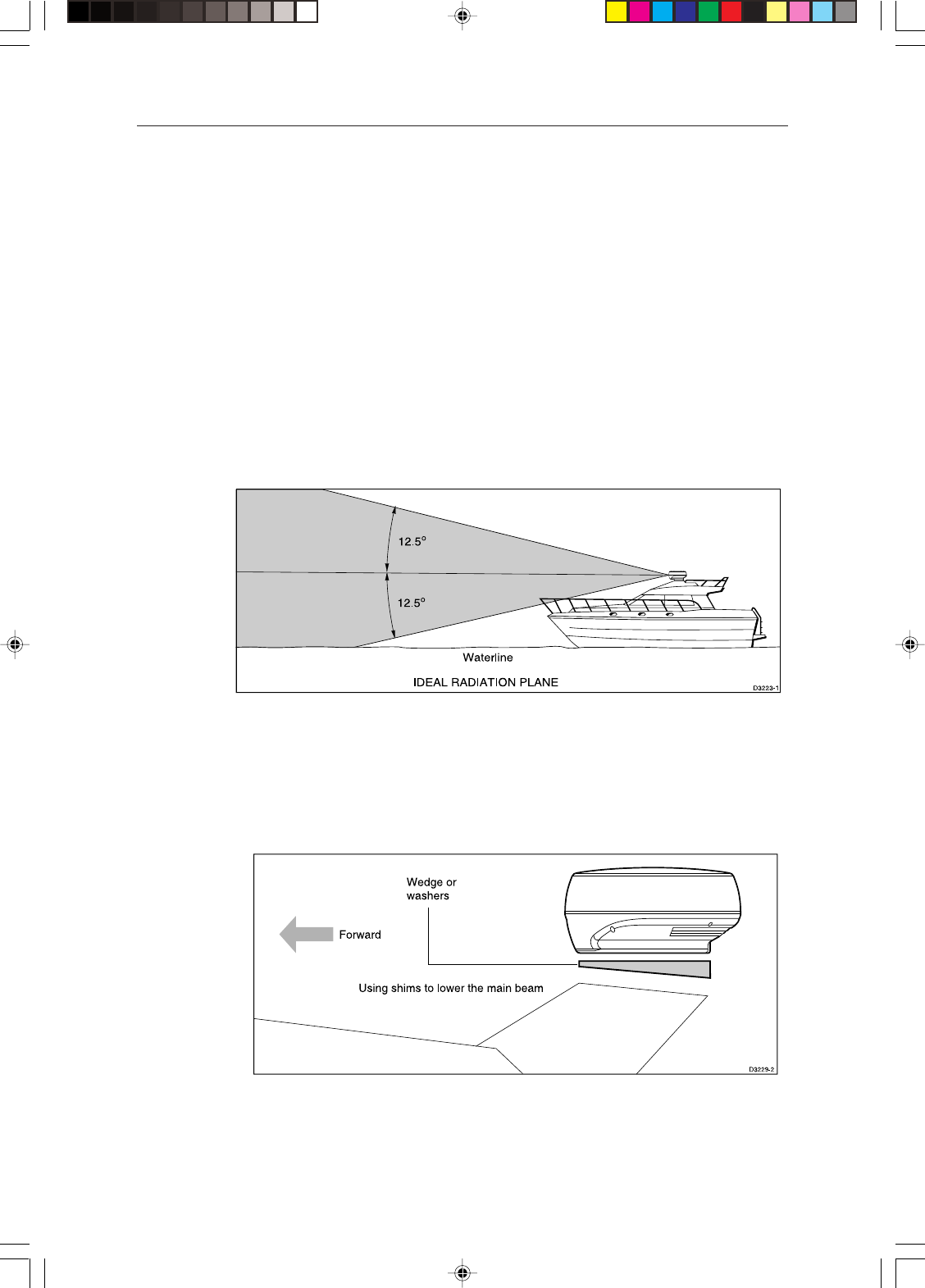
Setting the radiation plane
The scanner unit should be mounted so that the array rotates parallel to the
waterline. The radar beam is approximately 25° wide in the vertical direction,
providing good target detection during the vessel’s pitching and rolling.
Planing hull vessels, and some displacement hull vessels, adopt a higher bow
angle when the vessel is at its cruising speed. In many cases this substantially
alters and raises the radar’s main radiation plane, and can cause poor detection
of nearby targets. It may be helpful to lower the radar beam back towards the
parallel, by shimming the rear of the radar, so that the beam points slightly
downwards with respect to the waterline when the vessel is at rest.
The shims may be made from aluminium plate wedges, simple flat washers, or
an angled wooden block. For thick shims, you may need longer securing bolts
than the M8x40 bolts supplied with the radome scanner, or the M10 studding
supplied with the open array scanners.
154_2c1.p65 13/05/99, 13:179

10 Pathfinder Radar Scanners
1.4 Cable runs
You need to consider the following before installing the system cables:
– You need to fit the inter-unit cable and the power cable.
– All cables should be adequately clamped and protected from physical
damage and exposure to heat - avoid running cables through bilges or
doorways, or close to moving or hot objects.
– Acute bends must be avoided
– Where a cable passes through an exposed bulkhead or deckhead, a
watertight gland or swan neck tube should be used.
– Avoid cutting and re-joining cables (if necessary, refer to the notes below)
You need to run the following cables:
CAUTION
Do not pull the cable through bulkheads using a cord attached to the
connector. This could damage the connections.
•Inter-unit cable . A vinyl-covered and shielded cable is supplied with the
radome scanner unit. The cable has a connector plug at one end for
connecting to the display unit or extension cable; the other end of the radome
scanner cable is fitted with an 8-way plug and power cores (covered by a
clear protective sleeve) for connecting to the scanner.
For open array scanners, various length cables are available. These cables
have a connector plug at one end for connecting to the display unit or
extension cable; the other end is prepared ready to fit to the power and signal
connectors (see Section 2.2)
• Power cable, the scanner receives power via the display unit. The power
cable is supplied with the display unit. However, cable details are provided in
this section.
Rejoining Cables
You should avoid cutting and re-joining cables. If this is necessary you must:
• Fit a ferrite on each side of the join. The specific ferrite to use depends on the
cable type - contact Raytheom Marine for details.
• Take care not to damage any of the wires. Make sure that all the wires and, in
particular, the screen are reconnected correctly.
If you are mounting the scanner on the mast of a sailboat, and will need to
unstep the mast, you should install a suitable junction box inside the boat.
On a radome scanner, the junction box should provide an 11- or 13-way
terminal strip, depending on the number of power cores in your cable, with a
10 A rating. Also, you should keep the length of the un-screened coaxial cores
to less than 30 mm to maintain EMC conformance.
154_2c1.p65 13/05/99, 13:1710

Chapter 1: Overview 11
On an open array scanner, the junction box should provide a 13-way terminal
strip with a 20 A rating for power cores. It is essential that all 4 power cores are
connected and that the connection is of very low resistance as considerable
power passes through this connection. Also, you should keep the length of the
un-screened coaxial cores to less than 30 mm to maintain EMC conformance.
Inter-unit cable
The inter-unit cable entrance is at the rear of the scanner unit. If the unit is
mounted on a hollow mast the cable may be run inside the mast and then fed
through the radar’s cable entrance. Make sure that the cable does not chafe
where it enters and exits the mast.
Note: Route the cable from the display up to the scanner, since this will require
the smallest clearance hole.
CAUTION
The display connector on the inter-unit cable is a moulded plug that
cannot be replaced. DO NOT remove this moulded plug.
The inter-unit cable, for connecting the scanner to the display unit, depends on
your scanner package as follows:
Scanner PackageScanner Package
Scanner PackageScanner Package
Scanner Package Inter-Unit CableInter-Unit Cable
Inter-Unit CableInter-Unit Cable
Inter-Unit Cable
2D (US) 10 m light (2 power cores)
2DE (European) 15 m light (2 power cores)
4D 15 m heavy (4 power cores)
5S 5 m, 15 m or 5 m + 10 m extension
25 m heavy (24/32 V systems only)
The minimum bends permitted are:
Minimum bend, light cable 60 mm (~2.5 in) radius
Minimum bend, heavy cable 82 mm (~3.75 in) radius
Radome scanner cable
The length of the supplied cable should be sufficient to complete the cable run
required on most small vessels. For longer runs, additional or replacement
cables are available, which have 4 power cores to minimise voltage drops over
the longer cable run: these optional cables include 5 m and 10 m extension
cables, and a 25 m replacement cable.
The maximum inter-unit cable length is limited by the minimum supply
voltage, the scanner type (18" radome or 24" radome), and the cable type (2 or 4
154_2c1.p65 13/05/99, 13:1711

12 Pathfinder Radar Scanners
power cores): if a mix of light and heavy cables is used, only 2 power cores are
connected through.
Note: For vessels with 24 V power systems, any combination of inter-unit
cables can be used.
For vessels with 12 V power systems, the recommended cable(s) for different
run lengths are given in the following table, which assumes a minimum supply
voltage of 10.7 V (the lowest voltage likely to be reached by a 12 V battery in
normal marine use). Do not use cable combinations that are not included in
the table.
Recommended Radome Inter-Unit Cable(s) for Vessels with 12 V Power
Systems
Inter-Unit Cable Scanner Package
Length Required (m) 2D (US) 2DE (Eur) 4D
10 Std 10 m light N/A N/A
15 Std + 5 m ext Std 15 m light Std 15 m heavy
20 Std + 10 m ext 25 m assembly Std + 5 m ext
25 25 m assembly 25 m assembly Std + 10 m ext
30 25 m + 5 m ext 25 m + 5 m ext 25 m + 5 m ext
35 25 m + 10 m ext 25 m + 10 m ext 25 m + 10 m ext
Refer to the packing list in Section 1.2 for cable part numbers
Note: This table applies to systems using the standard 1.5 m power cable. If you
extend the power cable you may need to select different inter-unit cable(s), as
discussed in the following section Power Cable.
Open array scanner cable
Heavy duty cables are available in 5 m, 15 m and 25 m lengths which should be
sufficient to complete the cable run required on most small vessels. For longer
runs, 5 m and 10 m extension cables are available, both have 4 power cores to
minimise voltage drops over the cable run and incorporate in-line moulded
plugs .
The maximum inter-unit cable length is limited by the minimum supply
voltage and the scanner type.
154_2c1.p65 13/05/99, 13:1712

Chapter 1: Overview 13
12 V Systems
For vessels with 12 V power systems, the recommended cable(s) for different
run lengths are given in the following table, which assumes a minimum supply
voltage of 10.7 V (the lowest voltage likely to be reached by a 12 V battery in
normal marine use). Do not use cable combinations that are not included in
the table.
Recommended Open Array Inter-Unit Cable(s) for Vessels with 12 V Power
Systems
Inter-Unit Cable 4 kW Scanners
Length Required (m)
5 5m heavy
15 15 m heavy
15 5 m heavy + 10 m extension
Note: This table applies to systems using the standard 1.5 m power cable. If you
extend the power cable you may need to select different inter-unit cable(s), as
discussed in the following section Power Cable.
Refer to the packing list in Section 1.2 for cable part numbers
24 V and 32 V Systems
For vessels with 24 V and 32 V power systems, any combination of inter-unit
cable up to a maximum length of 35 m can be used.
Power cable - radome scanners
The radome radar systems are intended for use on ships’ DC power systems
operating in the 10.7 to 32 V DC range (that is, 12 V and 24 V systems, not 32 V
systems). A 1.5 m (5 ft) power cable is supplied (with the display unit) for
connecting the ship’s DC power to the radar scanner via the display unit. Refer
to the HSB Series Display Owner’s Handbook for details on connecting this
cable. This section provides details for extending the length of the power cable.
If a longer power cable run is required, use the supplied power cable to connect
to the display unit. Then use a suitable connector block to connect the free end
to the extension cable. The supplied power cable has a cross-section of
2.0 mm2.
Note: For vessels with 24 V power systems, the power cable may be extended
by up to 20 m using a wire gauge of 1.5 mm2 (AWG 16) or greater, irrespective
of the inter-unit cable length.
154_2c1.p65 13/05/99, 13:1713

14 Pathfinder Radar Scanners
For vessels with 12 V power systems, longer power cable runs may require
larger wire gauges to minimise any voltage drop in the cable. The scanner type
and the length and type of the inter-unit cable (see tables) also affect the wire
gauge required for the extension power cable. In order to determine the correct
supply cable size if the power cable must be extended, estimate the length of
cable between the ship’s main power source and the connector block, and then
select the wire size indicated by the distance and inter-unit cable in the
appropriate table following.
For example, you might have a 24" scanner, with 20 m between the scanner and
display unit, that you plan to connect by extending the supplied 15 m heavy
inter-unit cable with a 5 m extension cable. In addition, your 12 V power supply
might be 10 m from the display unit, requiring an extension of 8.5 m. To
determine the wire gauge required for the power cable extension, refer to the
table for the 24" scanner, go to the row labelled 15 m Heavy + 5 m ext, and read
across until you come to a maximum cable length greater than 8.5 m. This is the
10 m entry, in the column for 4.0 mm2 wire gauge.
Maximum Extension Power Cable Lengths (m), 12 V Systems with 18"
Radome Scanner
Inter-Unit Cable(s) Power Cable Core
mm2: 1.5 2.0 2.5 4.0 6.0 10.0
AWG: 16 15 14 11 10 7
10 m Light 5.0 7.0 9.0 14.0 20.0 35.0
10 m Light + 5 m ext 1.0 2.0 3.0 4.5 7.0 12.0
10 m Light + 10 m ext Do NOT extend the power cable
15 m Light 1.0 2.0 3.0 4.5 7.0 12.0
15 m Heavy 7.0 10.0 13.0 20.0 30.0 50.0
15 m Heavy + 5 m ext 5.0 7.0 10.0 15.0 25.0 40.0
25 m Heavy 4.5 6.0 8.0 12.0 20.0 35.0
25 m Heavy + 5 m ext 3.5 4.5 6.0 9.0 15.0 25.0
25 m Heavy + 10 m ext 2.0 3.0 4.0 6.0 9.0 15.0
Note: If you have an 18" radome scanner, and the wire gauge required for
your extended power cable is unacceptably large, you should replace the
supplied light (2 power core) inter-unit cable with the 25 m heavy (4 power
core) inter-unit cable assembly (see table).
154_2c1.p65 13/05/99, 13:1714

Chapter 1: Overview 15
Maximum Extension Power Cable Lengths (m), 12 V Systems with 24"
Radome Scanner
Inter-Unit Cable(s) Power Cable Core
mm2: 1.5 2.0 2.5 4.0 6.0 10.0
AWG: 16 15 14 11 10 7
15 m Heavy 5.0 7.0 9.0 14.0 20.0 35.0
15 m Heavy + 5 m ext 4.0 5.0 6.0 10.0 15.0 25.0
15 m Heavy + 10 m ext 2.0 3.0 4.0 7.0 10.0 17.0
25 m Heavy 2.0 3.0 4.0 7.0 10.0 17.0
25 m Heavy + 5 m ext 1.0 1.5 2.0 3.0 4.0 8.0
25 m Heavy + 10 m ext Do NOT extend the power cable
Power cable - open array scanners
The 48" 4 kW open array scanner is intended for use on ships’ DC power
systems operating in the 10.7 to 44 V DC range (that is, 12 V, 24 V and 32 V
systems). Open array scanners draw considerable power from the vessels
power source, especially in high wind speeds. It is essential for reliable
operation that the unit is supplied with a low resistance power cable system,
especially when operated from a 12 V power system.
CAUTION
Do not use the 48" Open Array Scanner with an SL70 or Autohelm 7”
LCD display unit. Failure to observe this may result in permanent damage
to the display unit.
12 V systems
Extensions to the supplied power cable must be kept to a minimum and the
power should be fed directly from the output of the battery isolator switch via
its own dedicated cable system. It is recommended that no additional power
switch is included in this power cable.
CAUTION
The display unit does not include a fuse for scanner power, so an in-line
fuse or circuit breaker rated at 20 A MUST be included in the power cable.
All power connections must be of high quality to minimise their resistance and
to remove the risk of accidental shorts. Recommended maximum power cable
extensions are given in the table below. These figures relate to the total cable
extension, from the end of the supplied 1.5 m power cable to the system battery
terminals. Do not exceed these lengths as unreliable operation may result.
154_2c1.p65 13/05/99, 13:1715

16 Pathfinder Radar Scanners
Maximum Extension Power Cable Lengths (m),
12 V Systems with 48" 4 kW Scanners
Power Cable Core Size (each core)
mm2: 4.0 6.0 8.0 10.0
AWG: 11 10 8 7
<3.0 4.5 6.0 7.5
Note: If the required extension results in unacceptably large diameter cables,
use two or more smaller gauge wires to achieve the required copper wire cross-
section. For example, using two pairs of 2 mm2 is equivalent to using two single
4.0 mm2 cables.
24 V and 32 V systems
These systems are less sensitive than 12 V systems to voltage loss in the power
cables. However, it is still necessary to use adequate cables to prevent excessive
power loss. The table below gives the recommended wire gauge for different
power cable extension lengths. Raytheon recommends that power is fed
directly from the output of the battery isolator switch via its own dedicated
cable system.
CAUTION
The display unit does not include a fuse for scanner power, so an in-line
fuse or circuit breaker rated at 10 A MUST be included in the power cable.
Maximum Extension Power Cable Lengths (m),
12 V Systems with 48" 4 kW Scanners
Power Cable Core Size (each core)
mm2: 2.0 4.0 6.0 8.0 10.0
AWG: 14 11 10 8 7
<8.0 16.0 24 32 35
Note: If the required extension results in unacceptably large diameter cables,
use two or more smaller gauge wires to achieve the required copper wire cross-
section. For example, using two pairs of 2 mm2 is equivalent to using two single
4.0 mm2 cables.
154_2c1.p65 13/05/99, 13:1716
Chapter 2: Installing the Scanner 17
Chapter 2: Installing the Scanner
2.1 Radome scanner
Securing the radome scanner to the mounting surface
CAUTION
The drain tube must always be used, but may be shortened if necessary
1. Using the paper template supplied with the scanner mounting kit, mark the
flat mounting surface with the mounting holes and drain tube hole, and drill
the holes as indicated on the template.
If it is impractical to drill a hole for the drain tube, then the scanner unit
should be mounted on 4 suitable spacers 10 mm high and the drain tube
length reduced by 10 mm. It will then be clear of the flat surface and can
still perform its function.
Note: If you are using a Raytheon mast mount bracket, the surface is pre-
prepared.
Note: If you are mounting the scanner on a flat surface, you may find it
easier to fit the drain tube, as described in the following section, before
securing the scanner.
2. Position the scanner on the mounting surface, ensuring that the cable inlet is
pointing aft.
3. Locate the bolts and washers supplied with the scanner, grease the bolts,
and secure the scanner to the mounting surface as shown in the following
diagram.
Scanner base
Mounting bracket
or mounting surface
Greased mounting bolt
D3995-2
Bitumen washer
You may need to use longer M8 mounting bolts to secure the scanner if you
have used shims to lower the radar beam.
154_2c2.p65 13/05/99, 13:1717
18 Pathfinder Radar Scanners
Connecting the radome scanner inter-unit cable
CAUTION:
Before wiring the scanner unit, make sure that the inter-unit cable is not
connected and power is not applied to the display unit.
When you have run the inter-unit cable to the scanner location, connect the
cable as follows:
1. Loosen the 4 (18") or 7 (24") screws securing the scanner cover. These
screws are captive and should remain assembled to the lower flange
assembly. Press the radome inwards to release the top. This breaks the seal
and makes removal easier.
2. To avoid losing the scanner cover, tie the cord, attached to the inside of the
base of the scanner, to the eye provided in the cover.
3. If you have a 24" scanner, unscrew and remove the inner cover:
D4006-1
Inner cover
4. Remove the drain tube from inside the base of the scanner, and insert it into
the drain hole as shown in the following diagram. Pull the tube gently from
outside the scanner so that it clips into place.
154_2c2.p65 13/05/99, 13:1818
Chapter 2: Installing the Scanner 19
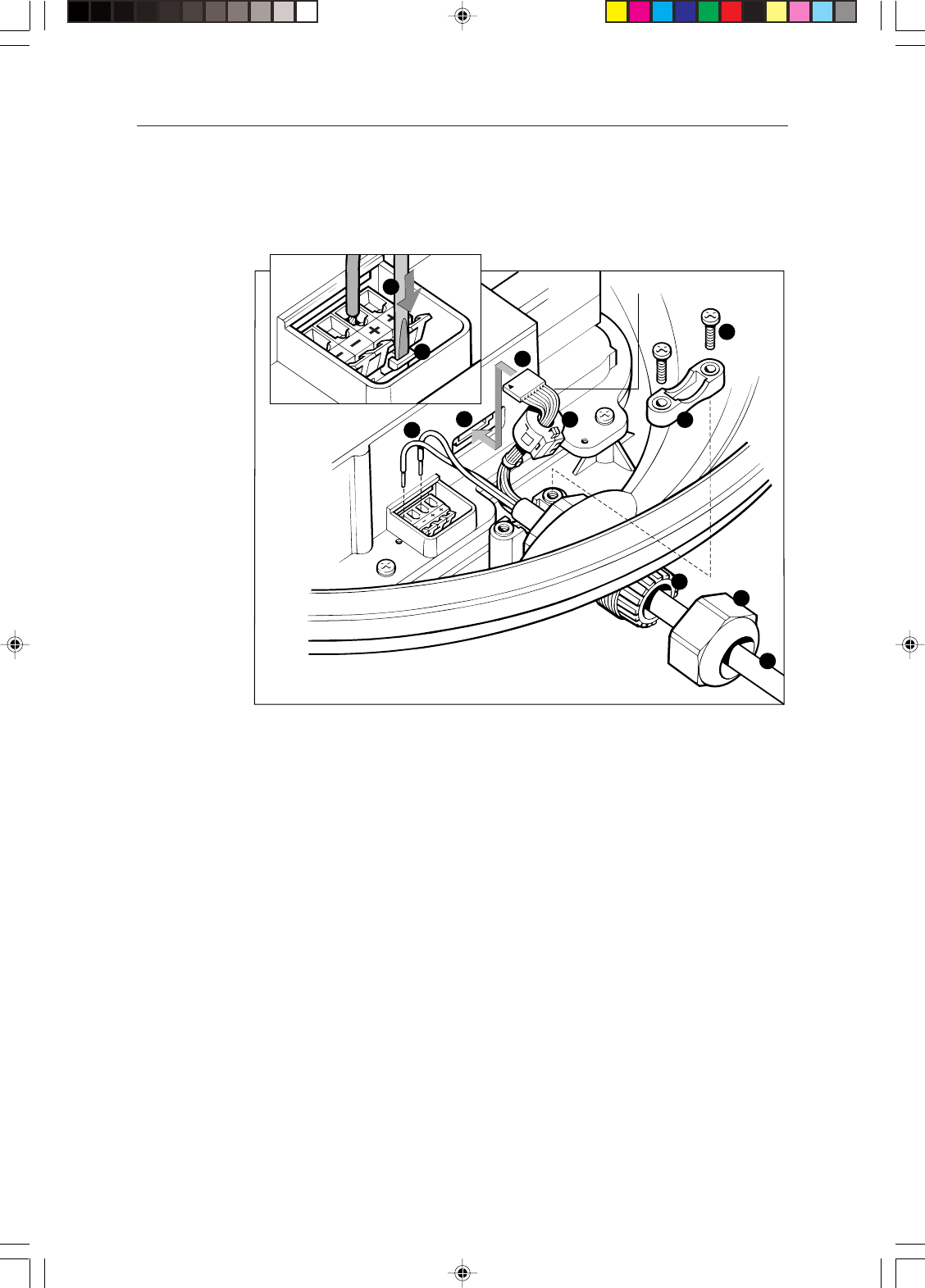
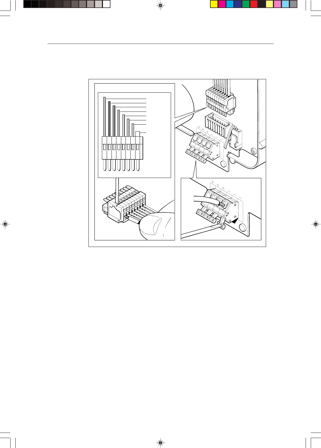
5. Referring to the following illustration, remove the securing nut (1) from the
watertight gland and grommet (2), where the inter-unit cable (3) will enter
the base.
D3230-3
10
4
59
White wire
6
3
1
2
11
7
8
1 Securing nut 2 Gland 3 Inter-unit cable 4 Eight-way plug 5 Eight-way socket 6 Power
cores (2 or 4) 7 Terminal clamp 8 Screwdriver 9 Cable clamp 10 Cable clamp screws 11
Ferrite clamp
6. Slide the gland nut onto the inter-unit cable (3), and insert the cable, still
covered by its protective sleeve, through the gland into the base.
7. Cut and remove the protective sleeve to expose the 8-way plug (4) and
power cores (6).
8. If the scanner is connected to an HSB Series Pathfinder Radar display, fit
the ferrite clamp (11), supplied loose with the display unit, as follows:
CAUTION
If any wires are damaged when the clamp is fitted, the scanner unit will
not function correctly.
- the ferrite clamp is supplied open. If the clamp has been closed, insert a
small, flat-blade screwdriver into the slots at the end of the clamp
opposite the hinge and twist gently.
- Position one-half of the clamp around the eight cores of the inter-unit
cable between the 8-way plug (4) and the cable clamp, as close to the 8-
way plug as possible. (It may be necessary to fit the clamp over the
154_2c2.p65 13/05/99, 13:1819

20 Pathfinder Radar Scanners
cable tie closest to the 8-way plug – this will not affect the ferrite
clamp’s function).
Note: on the 24" scanner, the clamp must be contained inside the inner
cover.
- With the clamp positioned correctly, close the clamp ensuring none of
the cores are trapped by the hinge, latch or the ferrite itself.
9. Connect the 8-way plug (4) to the connector (5). The correct fitting is with
the small arrow marked on the body of the plug facing upwards and to the
left hand side. The grey wire will then be at the left hand side and the white
wire will be at the right hand side.
10. Connect the red and black power cores (6).
If you have a 10 m or light 15 m inter-unit cable, there is one pair of cores.
Connect the red cable lead to one of the terminal sockets marked “+”, and
the black cable lead to one of the sockets marked “-”.
If you have a heavy 15 m inter-unit cable, there are two pairs of cores.
Connect the red cable leads to the terminal sockets marked “+”, and the
black cable leads to the terminal sockets marked “-”, with one lead in each
socket.
The terminal clamps (7) are operated using a screwdriver (8), as shown in
the inset diagram on the previous page.
CAUTION:
Do not earth the cable screen to the scanner. The radar system is earthed
via the display unit.
11. Secure the nut (1) on the watertight gland, making sure that it grips the
cable’s outer sheath.
12. Secure the cable with the cable clamp (9), using the two screws (10)
provided. The clamp can be installed either way up, depending on the
thickness of the cable: use the position that matches the profile of the cable.
CAUTION
It is essential that the drain tube is fitted and that the nut on the watertight
gland is adequately tightened. If this is not done, water could become
trapped in the scanner and cause irrepairable damage.
13. Tighten the securing nut (1) again to ensure a waterproof seal.
14. If you have a 4D scanner, replace the inner cover over the connectors.
15. Untie the cord from the scanner cover, and coil it up in the base of the
scanner unit so that it cannot foul the rotating antenna.
16. Replace the scanner cover, aligning the mark on the cover with the mark on
the scanner base above the cable gland, and tighten the 4 or 7 captive
screws. Do not over-tighten these screws.
154_2c2.p65 13/05/99, 13:1820

Chapter 2: Installing the Scanner 21
2.2 Open array scanner
Installation of the open array scanner should only be undertaken by a competent
installer. If you have any difficulty with the installation, please contact your
local Raytheon Marine dealer.
The open array scanner is supplied in two sections; the pedestal unit and the
antenna. The pedestal unit is secured from below the mounting platform. The
open array is then secured to the pedestal. Full details for mounting the scanner
are given below.
CAUTION
The pedestal unit has a protective cap fitted over the open array mounting
shaft. This cap must be left in place until the open array is fitted to the
pedestal in order to protect the co-axial pin which protrudes from the
pedestal.
WARNING
The open array scanner weighs 30 kg. For safety reasons it is
recommended that the unit is not lifted by one person.
The unit is fitted with lifting eyes (maximum SWL. 40 kg) to facilitate the
use of standard lifting accessories, e.g. rope, chain or strop. The safe
working load (SWL) of the lifting accessories should be 150 kg. Suitable
lifting equipment could include a crane, hoist, or an appropriate rigid,
overhead structure.
Alternatively, the unit is suitable for a two person lift. Care should be
taken to ensure that each person is standing on a stable surface, and that
the pedestal is held carefully to esure it cannot slip.
The T-bar beneath the open array antenna can be used to aid lifting.
You should never lift the scanner by holding onto the open array antenna.
Securing the pedestal to the mounting platform
1. Using the paper template supplied with the scanner mounting kit, mark the
flat mounting surface with the holes and drill as indicated on the template.
Refer to Section 1.2 when selecting the scanner unit site.
2. Stick the four self-adhesive bitumen washers over the mounting holes.
3. Ensure the lifting eyes are securely fitted to the top of the pedestal, and the
yellow protective cap is in place.
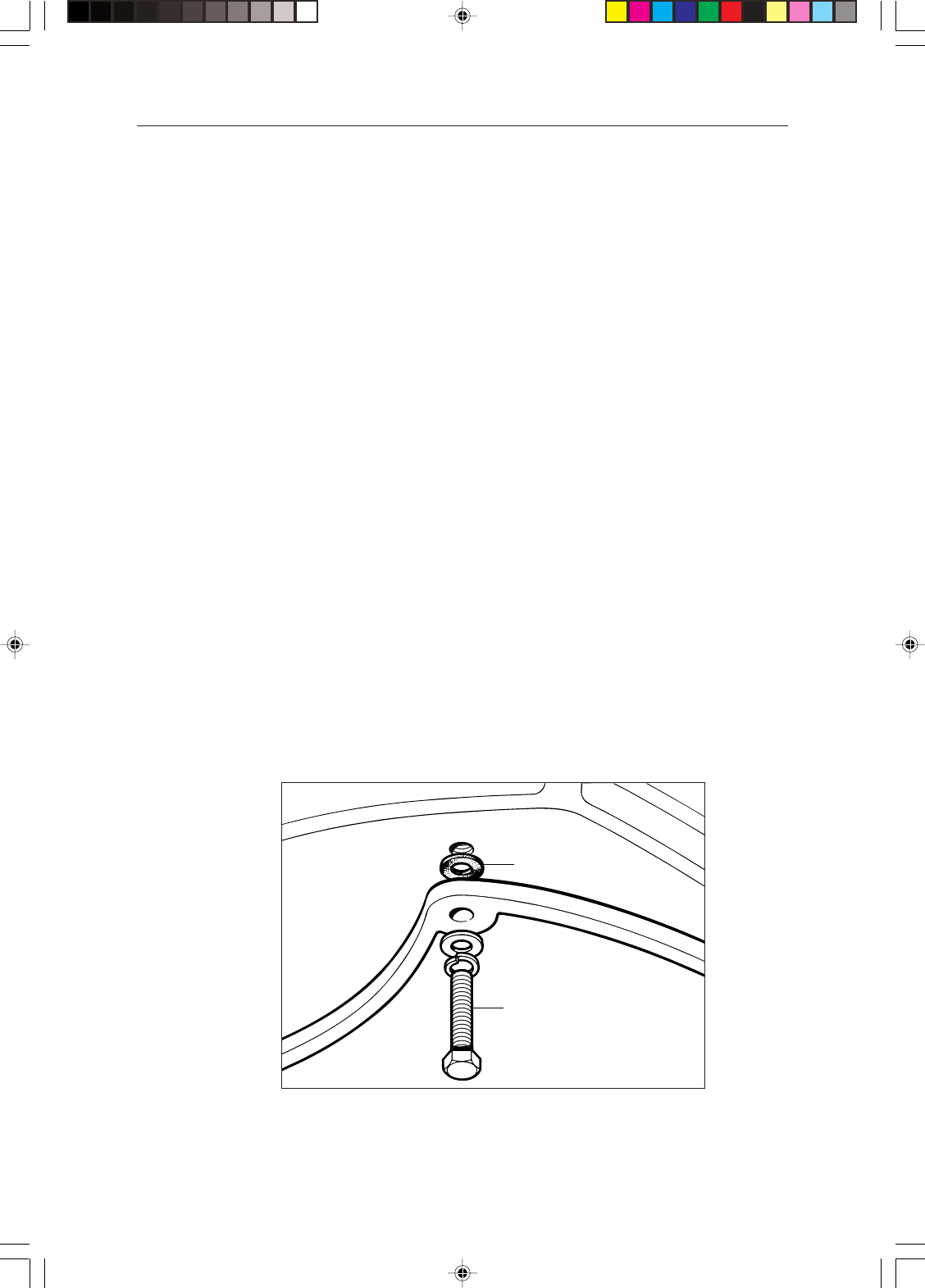
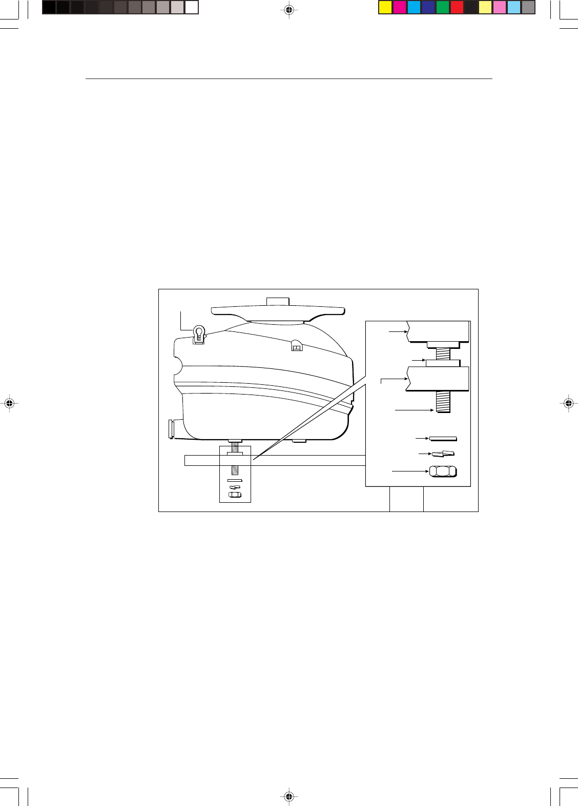
4. Grease the studs. Using two nuts locked together on the stud, screw each
studs into the pedestal until they bottom out. Remove these two nuts and
secure the studs with the fixings as shown in the following illustration.
Note: If the studding supplied is not long enough, use M10 stainless steel, grade
A4 studding of a suitable length. Refer to the following illustration for details.
154_2c2.p65 13/05/99, 13:1821
22 Pathfinder Radar Scanners
5. Using suitable lifting equipment, raise the pedestal over the mounting
surface. Carefully lower into position, taking care that the studs pass
through the holes without damaging the threads. Ensure that the cable inlet
is pointing aft.
WARNING
Support the pedestal unit until it has been secured to the mounting
platform. It is important that all four sets of nuts and washers are used to
secure the pedestal to the mounting platform.
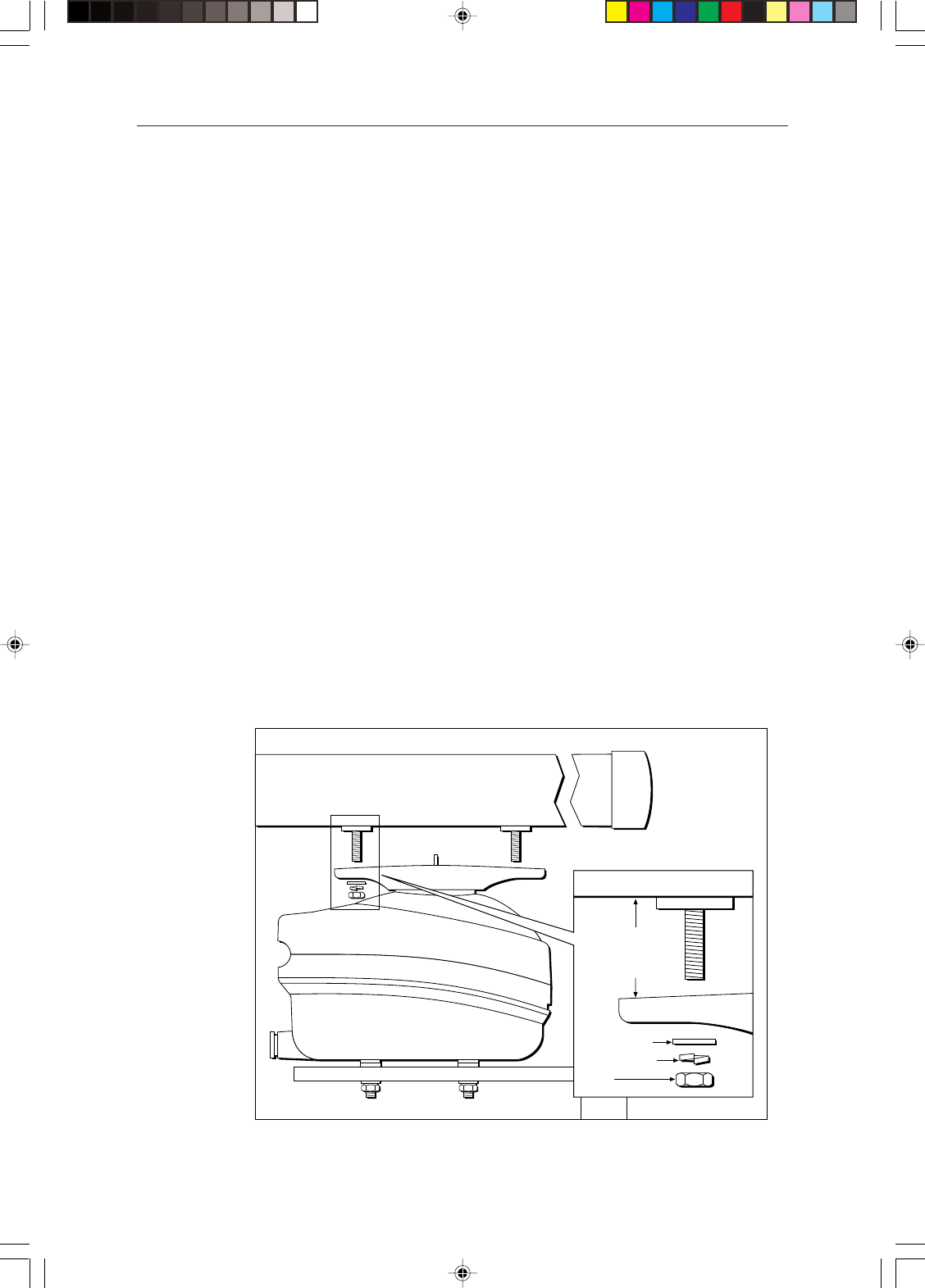
6. Referring to the following illustration, use the four nuts and associated
washers supplied to secure the pedestal.
Grease the nuts.
If required, cut-off any excess stud.
Pedestal
25mm (1in)
Bitumen washer,
sticky side down
on platform
Mounting
platform
Lifting eye
M10 plain washer
M10 spring washer
M10 stud
length = 52 mm
plus platform depth
M10 nut
D4573-1
154_2c2.p65 13/05/99, 13:1822
Chapter 2: Installing the Scanner 23
Connecting the open array scanner inter-unit cable
CAUTION:
Before wiring the scanner unit check that it is securely mounted to the
platform, then make sure that the inter-unit cable is not connected and
power is not applied to the display unit. The scanner switch must be in the
OFF position.
1. Loosen the four self-retaining bolts securing the pedestal lid to the base.
Pull-up and turn the bolts anti-clockwise to lock them in the upright
position. Remove the lifting eyes.
Note: Retain the lifting eyes: they will be required if the scanner is removed
from its platform.
2. Open the pedestal lid. Ensure the securing stay has automatically locked
into position.
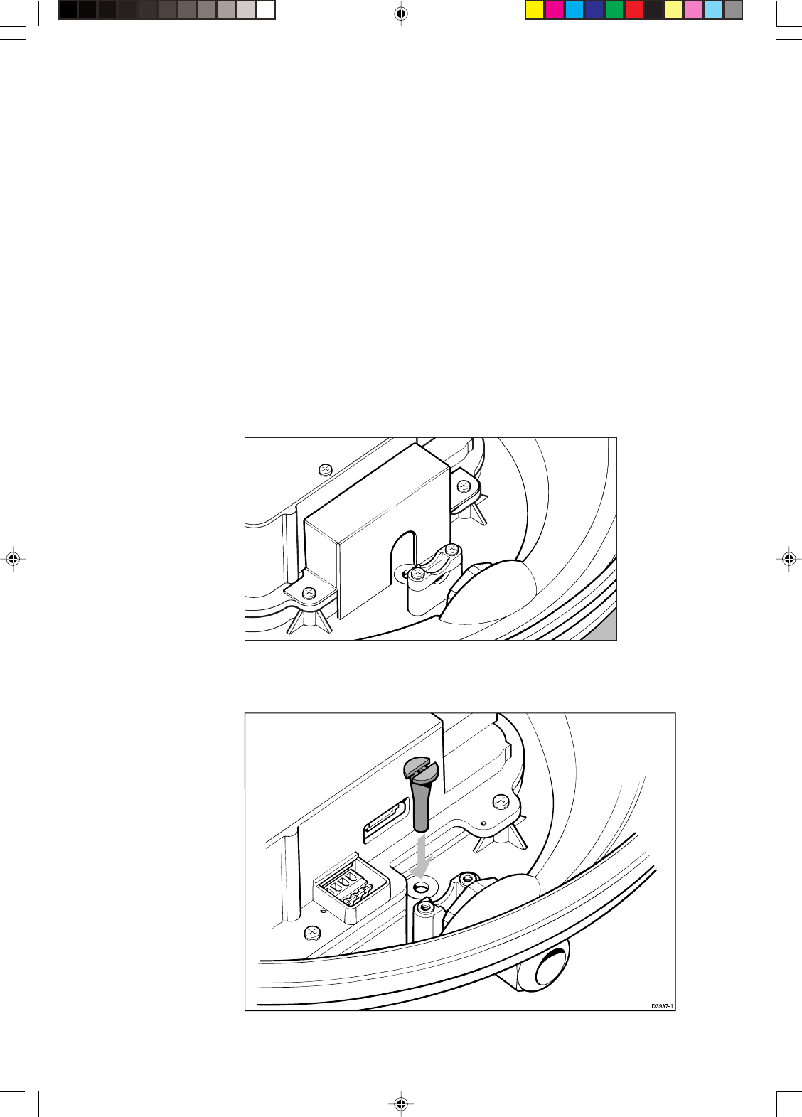
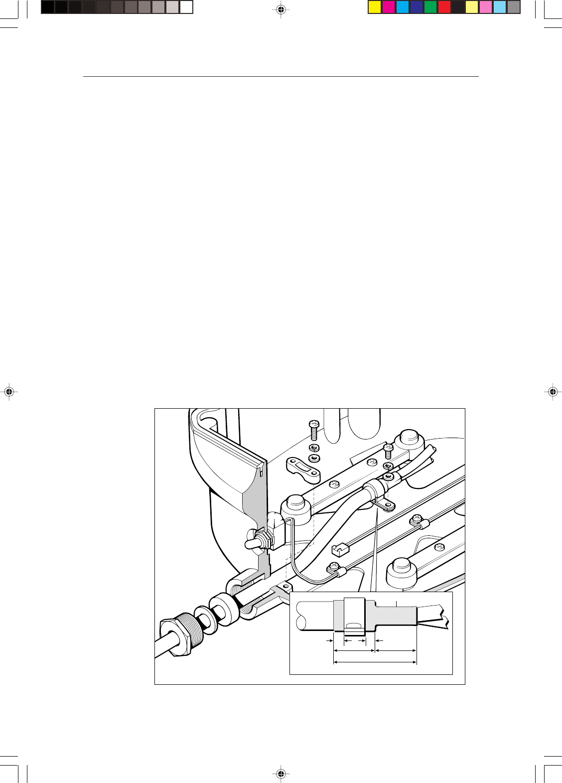
3. Referring to the following illustration, remove the cable gland nut, washer
and grommet from the watertight gland, where the inter-unit cable will
enter the base.
4. Slide the cable through the gland nut, washer and grommet, then into the
base. Clamp into position, ensuring the section of main cable covered in
yellow heatshrink is clamped.
D4575-1
20mm (0.8in)
40mm (1.6in)
20mm (0.8in)
5mm (0.2in) 5mm (0.2in)
Heatshrink
154_2c2.p65 13/05/99, 13:1823
24 Pathfinder Radar Scanners
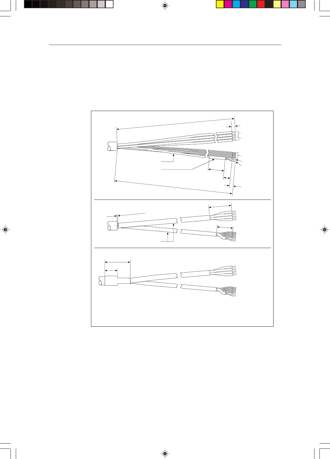
4. The cable is supplied prepared and ready to fit to the signal and power
connectors. If you need to cut the cable to length, strip off the protective
outer sleeve then use the supplied kit to prepare the cable as detailed in the
illustration below.
500mm ± 10mm
500mm ± 10mm
Black power wires
Data wires (6 off)
Coaxial signal
Coaxial screen
Red power wires
25mm
10mm
See Note B
35mm
5mm maximum
25mm
20mm
See Note A
See Note C
40mm
1. Preparation of Wires
2. Heat Shrinking of Wires
3. Heat Shrinking of Cable/Wires
Notes
A. Aluminium screen/polyester tape screen to remain.
B. Heat shrink sleeving fitted to keep the aluminium/polyester tape screen from unwinding
from the coaxial signal insulation.
C. The wires must be formed into two bundles with heat-shrink tubing (one containing the
four power wires and the other containing the eight signal wires).
D4579-1
5-6mm strip length
5-6mm strip length
CAUTION:
If any of the wires are incorrectly fitted, the scanner will not function
correctly.
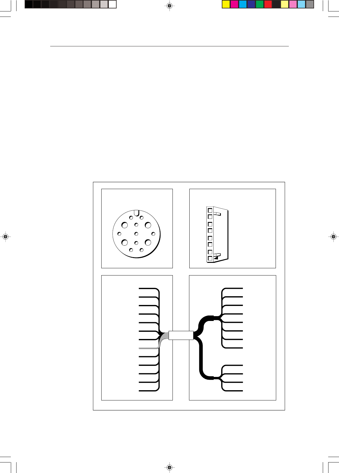
Remove the 8-way plug from the signal connector and fit to the cable as
shown in the following diagram. The terminal clamps are operated using a
screwdriver as shown in the diagram. Alternatively, you can leave the
connector in position whilst connecting the cable, you should then remove
the connector and visually check each wire connection.
154_2c2.p65 13/05/99, 13:1824
Chapter 2: Installing the Scanner 25
Re-connect to the plug. When correctly fitted the white wire (co-axial) will
be at the outer edge of the unit.
Grey
Purple
Blue
Green
Yellow
Orange
Coaxial Screen
(Black)
Coaxial Inner
(White)
Signal connector
Power connector
D4576-1
5. Connect the red and black power cores. Connect the red cable leads to the
terminal sockets marked “+”, and the black cable leads to the terminal
socket marked “-”, with one lead in each socket. The terminal clamps are
operated using a screwdriver as shown in the inset diagram.
CAUTION:
Do not earth the cable screen to the scanner. The radar system is earthed
via the display unit.
6. Using the tie-wrap fitting on the pedestal lid, secure the cable.
7. Close the pedestal lide, ensuring that the cable does not become trapped.
Tighten the four self-retaining bolts.
154_2c2.p65 13/05/99, 13:1825
26 Pathfinder Radar Scanners
Fitting the open array to the pedestal
CAUTION
The pedestal unit has a protective cap fitted over the open array mounting
shaft. This cap must be left in place until the open array is fitted to the
pedestal in order to protect the co-axial pin which protrudes from the
pedestal.
1. Remove the yellow cap from the open array shaft. Retain the cap, it will be
required if the open array is removed from the pedestal.
2. Grease the four securing studs.
CAUTION
If the pin is damaged during the following operation you should contact
your service dealer.
3. Lift the open array into position. Carefully lower the array - to prevent
damage to the mounting pin, ensure the array remains parallel to the
pedestal so that the studs slot into the holes on the pedestal mounting
bracket.
Note: The open array mounting bracket is designed so that the array can only
be fitted to the pedestal in the correct orientation.
4. Use the four nuts and associated washers supplied to secure the array to the
pedestal as shown in the diagram below.
D4580-1
M8 plain washer
M8 spring washer
M8 nut
Array
Pedestal
154_2c2.p65 13/05/99, 13:1826

Chapter 2: Installing the Scanner 27
2.3 System connections
DC power connection
Power is supplied to the scanner via the display unit; the power cable is supplied
with the display unit, refer to your display unit Owner’s Handbook for details
on connecting power. However, you should be aware of the following.
The DC system should be either:
• Negative grounded, with the negative battery terminal connected to the
ship’s ground.
• Floating, with neither battery terminal connected to the ship’s ground.
CAUTION:
This radar is not intended for use on “positive” ground vessels.
The power cable Earth screen connections must be connected to the ship’s
ground.
Grounding the radar system
It is important that an effective RF ground is connected to the radar system. You
must ground the radar by connecting the drain wire (screen) of the Power/
NMEA Input cable to the nearest ground point of the ship’s RF ground system.
Refer to your display unit Owner’s Handbook for details.
Note: Use only this ground connection.
Radome systems
The Radome radar system is intended for use on ships’ DC power systems
operating in the 10.7 to 32 V dc range (12 V and 24 V systems, not 32 V
systems). The connections should be made at a DC power distribution panel,
through an isolation switch or circuit breaker that is fused or trips at not greater
than 10 A. Check that all connection terminals are clean.
CAUTION:
If you do not have a breaker in your power circuit, you must fit an in-line
6.3 A quick-blow fuse to the positive (red) lead of the power cable.
Open array systems
The 5S 48" open array radar system is intended for use on ships’ DC power
systems operating in the 10.7 to 44 V DC range (that is, 12 V, 24 V and 32 V
systems). Raytheon recommends that power is fed directly from the output of
the battery isolator switch via its own dedicated cable system.
CAUTION
The display unit does not include a fuse for scanner power so an in-line
fuse or circuit breaker, rated at 20 A for 12 V systems or 10 A for 24 V and
32 V systems, MUST be included in the positive supply lead (red) of the
power cable.
154_2c2.p65 13/05/99, 13:1827
28 Pathfinder Radar Scanners
The open arrray scanner has a power switch fitted to the pedestal. This switch
can normally be left ON. However, if the scanner is being serviced or if any
personnel are in the vicinity of the open array, the switch should be set to OFF.
Scanner connection
The inter-unit cable is connected to the scanner as described in Sections 2.1 and
2.2. If you are using an inter-unit extension cable, connect this to the display
unit, and connect the supplied cable to the extension cable. The scanner
connector pins are shown in the following diagram, together with the
connections and core colours.
CAUTION
The display connector on the inter-unit cable is a moulded plug that
cannot be replaced. DO NOT remove this moulded plug.
1
2
35 4
7
10
11
86
9
13 12
White
Black
Orange
Black
Black
Green
Yellow
Shield
Red
Red
Violet
Blue
Grey
Video
Video RTN
*Battery --ve
Tx Trigger +
Battery --ve
Data I/O +
Tx Trigger --
Battery +ve
Data I/O --
*Battery +ve
Azimuth +
Azimuth --
1
2
3
4
5
6
7
8
9
10
11
12
13
White
Black
Orange
Yellow
Green
Blue
Violet
Grey
Red
Red
Black
Black
8
7
6
5
4
3
2
1
Video
Video Rtn
Tx Trigger +
Tx Trigger --
Data I/O +
Data I/O --
Azimuth +
Azimuth --
Battery +ve
*Battery +ve
*Battery --ve
Battery --ve
Not fitted
on Open Array Scanners
(refer to Section 2.2)
D4290-2
Front view of
Display Cable Connector Front view of Radome
Scanner Cable Connector
2
1
4
3
6
5
8
7
Display Scanner
* Not present on 'light', 11 core cables.
Battery +ve/--ve = 12 or 24v.
154_2c2.p65 13/05/99, 13:1828
Chapter 2: Installing the Scanner 29
Display unit connection
CAUTION
Do not use the 48" open array scanner with an SL70 or Autohelm 7” LCD
display unit. Failure to observe this may result in permanent damage to
the display unit.
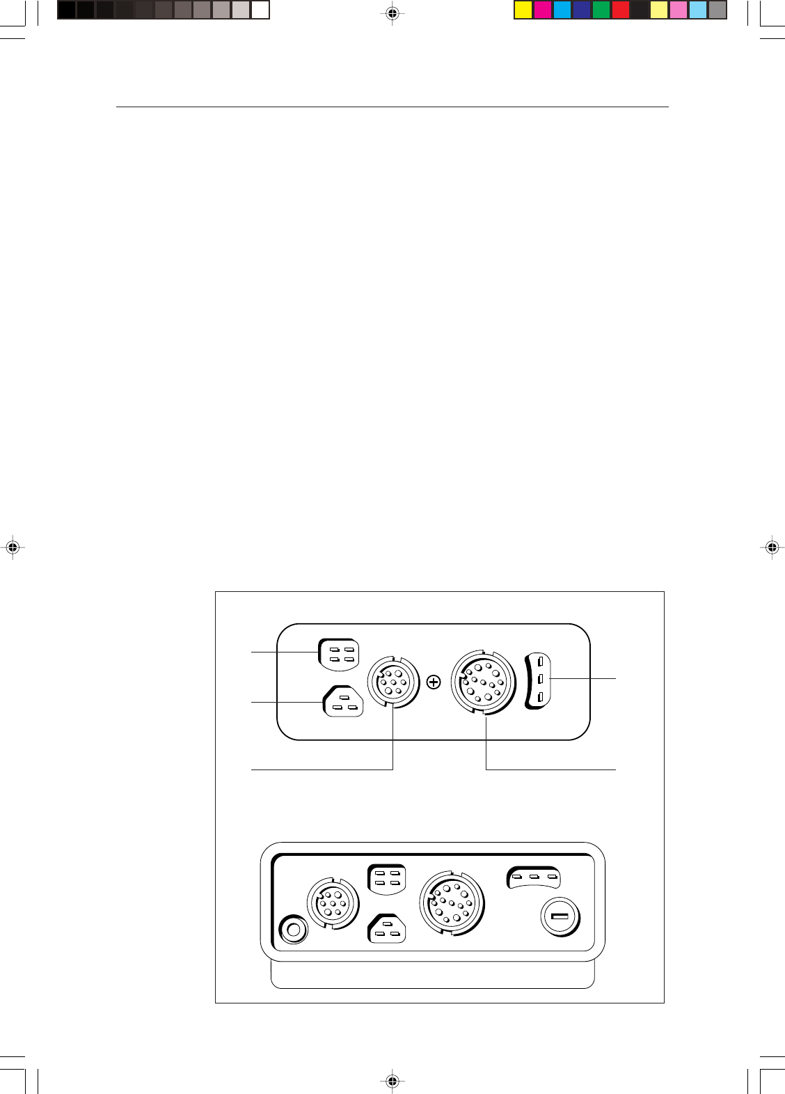
The rear of the Pathfinder display provides the following connection sockets:
•Scanner connection
•HSB, for connecting to another HSB Series display (such as a chartplotter or
second radar display) – not available on SL70 display
•SeaTalk, for SeaTalk data input and output and connecting to another HSB
Series display (such as a chartplotter or second radar display)
•NMEA Output – not available on SL70 display:
Note: For the SL70 display, NMEA OUT can be selected instead of SeaTalk.
•Power/NMEA Input, for 12 V, 24 V or 32 V (open array) DC power
connection, two NMEA 0183 inputs and one RF ground (screen)
connection.
Connect the scanner cable to the scanner connector (5) and power to the power/
NMEA input connector (3).
Power and all other connector details are supplied in the display unit Owner’s
Handbook.
POWER/
NMEA ANTENNA/
TRANSDUCER
NMEA SeaTalk
DISPLAY
FUSE
HSB
1
2
3
4
5
LCD Display Connector Panel
CRT Display Connector Panel
D4597_1
1 NMEA Output 2 HSB 3 Power and NMEA Input 4 SeaTalk 5 Scanner
154_2c2.p65 13/05/99, 13:1829

30 Pathfinder Radar Scanners
154_2c2.p65 13/05/99, 13:1830

Chapter 3: Systems Test and Post Installation Alignment 31
Chapter 3:
System Tests and Post Installation Alignment
Once you have installed your radar scanner and display unit, and made all the
connections, you need to check your installation. You can then set up the radar
system, align the scanner and check the display timing.
Set up, alignment and timing checks are performed from the radar system
display unit. The procedures are outlined below; full details are provided in the
display unit Owner’s Handbook. You should read the Pathfinder radar display
unit Owner’s Handbook and familiarise yourself with the operation of the
radar.
System check
Before performing the functional test, check the following:
• All securing bolts are fully tightened and mechanical locking arrangements
as specified are in place
• All connections have been made
• All connecting wires are secured and protected as necessary
Note: If you are the boat owner and have performed the installation yourself,
ask your authorised installation dealer to check the installation before going to
sea.
Set up, alignment and timing checks
Switch on and initial set up
On the 48" open array scanner, ensure the power switch on the pedestal is set to
ON.
To switch on the display unit, press and hold the POWER key until the unit
beeps. The magnetron warm-up sequence should start, after which the unit
should enter Standby mode.
If necessary, adjust the lighting and contrast.
If required, change the default language settings.
Checking transmission
WARNING:
The radar scanner transmits electromagnetic energy. Ensure that the
scanner has been installed according to the recommendations given in
Chapter 1, and that all personnel are clear of the scanner, before switching
to transmit mode.
154_2c3.p65 13/05/99, 13:1831

32 Pathfinder Radar Scanners
Run through the radar operations described in the display unit Owner’s
Handbook and check that all the expected data is displayed.
Bearing alignment
When the system is correctly installed, you must check the bearing alignment to
ensure that targets appear at their correct bearing relative to the ship’s bow, and
adjust the alignment if necessary.
Display timing adjustment
The display timing can be affected by the length of the cable used to connect the
scanner to the display unit. This in turn affects the short range accuracy shown
on the display.
If you have extended your inter-unit cable, you will need to check the display
timing before using the system for navigation.
154_2c3.p65 13/05/99, 13:1832

Appendix 1: Specification 33
Appendix A: Specification
2D 18" Radome Scanner Unit
General
Approvals
CE - conforms to 89/336/EEC (EMC), EN60945:1997
FCC - conforms to Part 80 (47CFR) and Part 2 (47CFR)
Dimensions Φ468 x 227 mm (18.4 x 8.9 in)
Weight 6.5 kg (14.3 lbs)
Input Voltage 8.7 - 32 V DC (from display unit)
Power Consumption 28 W (9 W Standby)
Environmental Waterproof to CFR46
Temperature range: -10° to +55°C
Humidity limit: up to 95% at 35°C
Maximum wind speed for satisfactory operation: 100 Kts
Maximum Range Scale 24 nm
Transmitter
Transmitter Frequency 9410 +/– 30 MHz
Peak Power Output 2.0 kW (nominal)
Transmitter Solid-state modulator driving Magnetron
Pulse Length/PRF 0.08µs/2250Hz (0.75 nm or less)
0.25 µs/1500 Hz (above 0.75 nm and less than 6 nm)
0.70 µs/750 Hz 6 nm or greater)
Standby Mode Magnetron heater and control left on, all other services off
Duplexer Circulator
Antenna
Antenna Type Patch array
Beam Width (nominal) 5.1° horizontal, 25° vertical
Polarisation Horizontal
Antenna Side lobes Less than -22 dB
Rotation Rate 24 rpm (nominal)
154_2ap1.p65 13/05/99, 13:1833

34 Pathfinder Radar Scanners
Receiver
IF Frequency 60 MHz (nominal)
Receiver Characteristic Semi-log
Receiver Noise Figure Less than 5 dB (including Low Noise Converter/Limiter)
Receiver Bandwidth Bandwidth 12/3/1 MHz
4D 24" Radome Scanner Unit
General
Approvals
CE - conforms to 89/336/EEC (EMC), EN60945:1997
FCC - conforms to Part 80 (47CFR) and Part 2 (47CFR)
Dimensions Φ599 x 227 mm (23.6 x 8.9 in)
Weight 7.5 kg (16.5 lbs)
Input Voltage 8.7 - 32 V DC (from display unit)
Power Consumption 34 W (10 W Standby)
Environmental Waterproof to CFR46
Temperature range: -10° to +55°C
Humidity limit: up to 95% at 35°C
Maximum wind speed for satisfactory operation: 100 Kts
Maximum Range Scale 48 nm
Transmitter
Transmitter Frequency 9410 +/– 30 MHz
Peak Power Output 4.0 kW (nominal)
Transmitter Solid-state modulator driving Magnetron
Pulse Length/PRF 0.08µs/2250Hz (0.75 nm or less)
0.25 ms/1500 Hz (above 0.75 nm and less than 6 nm)
0.70 ms/750 Hz (6 nm or greater)
Standby Mode Magnetron heater and control left on, all other services off
Duplexer Circulator
154_2ap1.p65 13/05/99, 13:1834

Appendix 1: Specification 35
Antenna
Antenna Type Patch array
Beam Width (nominal) 3.9° horizontal, 25° vertical
Polarisation Horizontal
Antenna Side lobes Less than -22dB
Rotation Rate 24 rpm (nominal)
Receiver
IF Frequency 60 MHz (nominal)
Receiver Characteristic Semi-log
Receiver Noise Figure Less than 5 dB (including Low Noise Converter/Limiter)
Receiver Bandwidth 12/3/1 MHz
5S 48" Open Array Scanner Unit
General
Approvals
CE - conforms to 89/336/EEC (EMC), EN60945:1997
FCC - conforms to Part 80 (47CFR) and Part 2 (47CFR)
Dimensions Pedestal: 427 x 296 x 406 mm (16.8 x 10.5 x 16 in)
Array: 1306 mm (51.4 in) length
Weight Pedestal: 24 kg
Array: 6 kg
Input Voltage 7 - 44 V DC (from display unit)
Power Consumption 9.2 W Standby
46 W Typical operation in light winds
61 W Max. operation in 50 Kt winds
96 W Max. operation in 100 Kt winds
Environmental Waterproof to CFR46
Operating Temperature range: -10° to +55°C
Humidity limit: up to 95% at 35°C
Maximum wind speed for satisfactory operation: 100 Kts
Maximum Range Scale 72 nm
154_2ap1.p65 13/05/99, 13:1835

36 Pathfinder Radar Scanners
Transmitter
Transmitter Frequency 9410 +/– 30 MHz
Peak Power Output 4 kW (nominal)
Transmitter Solid state modulator driving magnetron
Pulse Length/PRF 0.06 µs/3,000 Hz (0.125 nm, 0.25 nm)
0.09 µs/3,000 Hz (0.50 nm, 0.125 nm exp, 0.25 exp)
0.15 µs/3,000 Hz (0.75 nm, 0.50 nm exp)
0.25 µs/3,000 Hz (0.75 nm exp)
0.35 µs/2,000 Hz (1.5 nm)
0.45 µs/1,600 Hz (3.0 nm, 1.5 nm exp)
0.60 µs/1,200 Hz (3.0 nm exp)
1.00 µs/740 Hz (6.0 nm or greater)
Note:Note:
Note:Note:
Note:
If the scanner is bought to use with an existing display, contact your dealer/service agent for the latest software.
Standby Mode Magnetron heater and control left on, all other services off
Duplexer Circulator
Antenna
Antenna Type Slotted waveguide array
Beam Width (nominal) 1.85°
Polarisation Horizontal
Antenna Side lobes Less than -22 dB
Rotation Rate 24 rpm (nominal)
Receiver
IF Frequency 60 MHz (nominal)
Receiver Characteristic Semi-log
Receiver Noise Figure Less than 5 dB
(including Low Noise Converter/Inverter & IF Receiver)
Receiver Bandwidth 12/3/0.7/0.5 MHz
154_2ap1.p65 13/05/99, 13:1836

Index 37
Index
Symbols
18" Radome
Specification 33
24" Radome
Specification 34
48" Open Array
Specification 35
A
Alignment 31
Bearing 32
B
Bearing Alignment 32
C
Cable Runs 10
Cables
Extension 3, 4
Extension - 18" Radome 14
Extension - 24" Radome 15
Extension - Open Array 13, 16
Extension - Radome 11, 12
Inter-unit 3, 4, 10
Inter-unit - Open Array 13, 24
Inter-unit - Radome 11, 12, 18
Power 10
Power - Open Array 15
Power - Radome 13
Connections
Display Unit 29
Open Array Scanner 23
Power 29
Radome Scanner 18
Scanner 28
System 27
D
Display Timing Adjustment 32
E
Electromagnetic Energy i, 31
EMC iii
Conformance iii
Installation Guidelines 2
F
Ferrite 2, 3, 19
G
Grounding the System 27
H
High Voltage i
L
Location 5
M
Mounting
Open Array Scanner 21
Radome Scanner 17
Scanner
on Power Boats 9
on Sailboats 8
N
Navigation Aid i
O
Open Array Scanner
48" iii, 1, 4
Connecting 23
Mounting 21
Power Connection 27
154_2idx.p65 13/05/99, 13:1837

Pathfinder Radar Scanners
38
P
Power
Cable 10
Cable - Open Array 15
Cable - Radome 13
Connection - Open Array 27
Connection - Radome 27
Connections 29
R
Radar System
Connections 27
Grounding 27
Item List 3
Typical System Diagram 1
Radome Scanner
18" iii, 1, 3
24" iii, 1, 3
Connecting 18
Mounting 17
Power Connection 27
S
Safety i
Electromagnetic Energy i
High Voltage i
Navigation Aid i
Scanner i.
See also
Open Array
Scanner; Radome Scanner
Connections 28
Location 5
Mounting
on Power Boats 9
on Sailboats 8
Set Up 31
Specification 33
18" Radome 33
24" Radome 34
48" Open Array 35
System Check 31
System Test 31
T
Timing Adjustment 32
Timing Checks 31
Transmission Check 31
W
Warranty iii
154_2idx.p65 13/05/99, 13:1838

Limited Warranty Certificate
Raytheon Marine Company warrants each new Light Marine/Dealer Distributor Product to be of good materials
and workmanship, and will repair or exchange any parts proven to be defective in material and workmanship
under normal use for a period of 2 years/24 months from date of sale to end user, except as provided below.
Defects will be corrected by Raytheon Marine Company or an authorized Raytheon dealer. Raytheon Marine
Company will, except as provided below, accept labor cost for a period of 2 years/24 months from the date of sale
to end user. During this period, except for certain products, travel costs (auto mileage and tolls) up to 100 round
trip highway miles and travel time of 2 hours, will be assumed by Raytheon Marine Company only on products
where proof of installation or commission by authorised service agents, can be shown.
Warranty Limitations
Raytheon Marine Company Warranty policy does not apply to equipment which has been subjected to accident,
abuse or misuse, shipping damage, alterations, corrosion, incorrect and/or non-authorized service, or equipment
on which the serial number has been altered, mutilated or removed.
Except where Raytheon Marine Company or its authorized dealer has performed the installation, it assumes no
responsibility for damage incurred during installation.
This Warranty does not cover routine system checkouts or alignment/calibration, unless required by replacement
of part(s) in the area being aligned.
A suitable proof of purchase, showing date, place, and serial number must be made available to Raytheon Marine
Company or authorized service agent at the time of request for Warranty service.
Consumable items, (such as: Chart paper, lamps, fuses, batteries, styli, stylus/drive belts, radar mixer crystals/
diodes, snap-in impeller carriers, impellers, impeller bearings, and impeller shaft) are specifically excluded from
this Warranty.
Magnetrons, Cathode Ray Tubes (CRT), hailer horns and transducers are warranted for 1 year/12 months from
date of sale. These items must be returned to a Raytheon Marine Company facility.
All costs associated with transducer replacement, other than the cost of the transducer itself, are specifically
excluded from this Warranty.
Overtime premium labor portion of services outside of normal working hours is not covered by this Warranty.
Travel cost allowance on certain products with a suggested retail price below $2500.00 is not authorized. When/
or if repairs are necessary, these products must be forwarded to a Raytheon Marine Company facility or an
authorized dealer at owner’s expense will be returned via surface carrier at no cost to the owner.
Travel costs other than auto mileage, tolls and two (2) hours travel time, are specifically excluded on all products.
Travel costs which are excluded from the coverage of this Warranty include but are not limited to: taxi, launch
fees, aircraft rental, subsistence, customs, shipping and communication charges etc..
Travel costs, mileage and time, in excess to that allowed must have prior approval in writing.
TO THE EXTENT CONSISTENT WITH STATE AND FEDERAL LAW:
(1) THIS WARRANTY IS STRICTLY LIMITED TO THE TERMS INDICATED HEREIN, AND NO
OTHER WARRANTIES OR REMEDIES SHALL BE BINDING ON RAYTHEON MARINE COMPANY
INCLUDING WITHOUT LIMITATION ANY WARRANTIES OF MERCHANTABLE OR FITNESS FOR
A PARTICULAR PURPOSE.
(2) Raytheon Marine Company shall not be liable for any incidental, consequential or special (including punitive
or multiple) damages.
All Raytheon Marine Company products sold or provided hereunder are merely aids to navigation. It is the
responsibility of the user to exercise discretion and proper navigational skill independent of any Raytheon
equipment.
44592-4
9th November 1998
warranty.p65 13/05/99, 13:1839

Purchased from Purchase date
Dealer Address
Installed by Installation date
Commissioned by
Owner’s name
Mailing address
This portion of card should be completed and retained by the owner.
Factory Service Centers
United States of America
Raytheon Marine Company
address as above
UK, Europe, Middle East, Far East
Raytheon Marine Company
address as above
United States of America
Raytheon Marine Company Tel 603-647-7530
Recreational Products Fax 603-634-4756
676 Island Pond Road
Manchester, NH 03109-5420
U.S.A.
UK, Europe, Middle East, Far East
Raytheon Marine Company Tel (44) 1705 693611
Recreational Products Fax (44) 1705 694642
Anchorage Park, Portsmouth Fax Customer support (44) 1705 661228
PO3 5TD, England
Commissioning date
Stick barcode label here
warranty.p65 13/05/99, 13:1840
Attn: Warranty Department
Raytheon Marine Company
Recreational Products
676 Island Pond Road
Manchester NH 03109-9953
USA
BUSINESS REPLY MAIL
FIRST CLASS MAIL PERMIT NO. 369 MANCHESTER NH
POSTAGE WILL BE PAID BY ADDRESSEE
NO POSTAGE
NECESSARY
IF MAILED
IN THE
UNITED STATES
Raytheon Marine Company
Recreational Products
Freepost PT 1127
Portsmouth
PO3 5BR
England
Note: This information is held by Raytheon Marine only
and shall not be made available to any other companies.
Raytheon Marine may send you mailshots/details of any
new products.
Please tick this box
❐
if you do not wish to receive any
further information from Raytheon Marine.
NO STAMP REQUIRED IF POSTED IN THE UK.
warranty.p65 13/05/99, 13:1841
Purchased from
Dealer address
Installed by Installation date
Owner’s name
Mailing address
North and South America
Detach and mail this portion within 48 hours.48 hours.
48 hours.48 hours.
48 hours.
To validate the warranty, the customer or dealer must fill in
the requested information below and mail to address shown
on front.
Retain other portion for your records.
Commissioned by Commissioning date
Purchase date
Purchased from
Dealer address
Installed by Installation date
Owner’s name
Mailing address
UK, Europe, Middle East and Far East
Detach and mail this portion within 48 hours.48 hours.
48 hours.48 hours.
48 hours.
To validate the warranty, the customer or dealer must fill in
the requested information below and mail to address shown
on front.
Retain other portion for your records.
Commissioned by
Boat’s name/Boat type/Location
Commissioning date
Purchase date
Stick barcode label here
Stick barcode label here
Owner’s occupation
Boat’s name/Boat type/Location
Owner’s occupation
warranty.p65 13/05/99, 13:1842

warranty.p65 13/05/99, 13:1843

warranty.p65 13/05/99, 13:1844