Raytheon Anschuetz High Seas RAY53 VHF-FM Marine Band Transceiver with DSC User Manual ray53 Manu
Raytheon Anschuetz GmbH High Seas Products VHF-FM Marine Band Transceiver with DSC ray53 Manu
Manual
1. OPERATION
1.1 INTRODUCTION
Your RAY53 has the capability to transmit and receive on all available US,International
and Canada Marine VHF radiotelephone channels. There are channels that are FCC
approved but may only be used by authorized stations for specific purposes, depending
on the type of vessel (commercial or noncommercial.) Refer to Table 1-1 . These table
list all of the marine VHF channels available in your RAY53 for Canada,International and
U.S. radiotelephone use. Full familiarization with this table is essential when selecting
your channels. The International frequencies were agreed upon by the attending
countries at the 1968 International Telecommunication Union meeting in Geneva and are
in active use around the world. The US channels are those channels authorized for use in
the U.S.A. by the FCC.
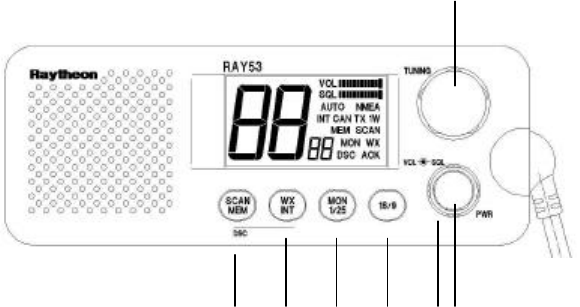
1.2 CONTROLS AND LCD DISPLAY
1)
4) 5) 6) 7) 2) 3)
1.2.1 Controls
1) Channel Selection (Knob)
-. Turning to the right can increase the channel number and it can be
decreased by turning to the left.
-. When the Channel Selection Knob is rotated to the right at “88CH”, the channel
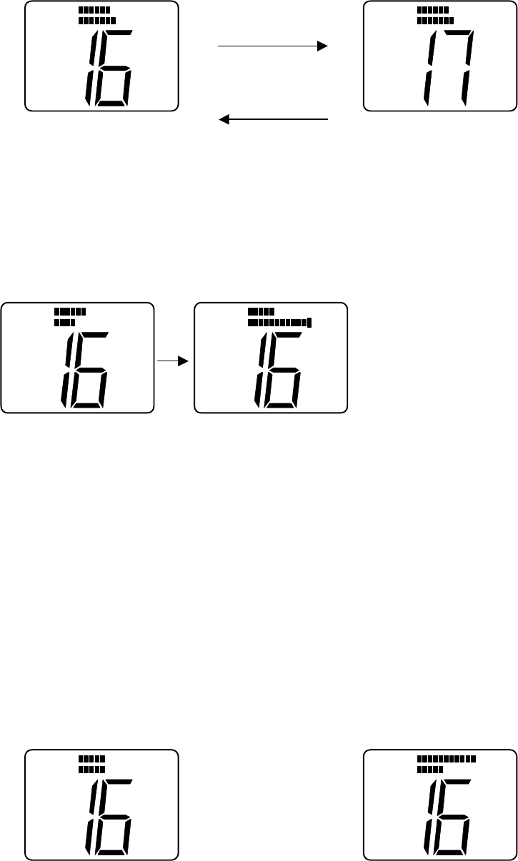
number becomes “01CH”.
-. When the Channel Selection Knob is rotated to the left at “01CH”, the channel
number becomes “88CH”.
(UP)
Rotate clockwise
(DOWN)
Rotate counter clockwise
2) Squelch Knob
-. When Squelch knob is rotated, the squelch level is adjusted. If the knob is rotated
completely clockwise,all bars will illuminate.
Rotate
Clockwise
3) Volume Knob
-. The volume knob controls the audio volume and is also switched to turn power on
and off. When the knob is rotated clockwise from the “OFF” position,the power
becomes “Turned On”. Being rotated clockwise,the audio volume will be
increased. Being rotated counterclockwise,the audio volume will be decreased.
(Volume UP)
NMEA
VOL
SQL
NMEA
VOL
SQL
NMEA
VOL
SQL
NMEA
VOL
SQL
NMEA
VOL
SQL
NMEA
VOL
SQ
L

Rotate clockwise
(Volume DOWN)
Rotate counter clockwise
-. When the power is turned on, the receiving mode is in use after the following
initial setting.
Initial setting at power on.
Frequency mode--------: the frequency mode at power OFF
Channel --------: 16 CH (Working CH)
Priority CH --------: Priority CH at power OFF
Weather CH --------: Weather CH at power OFF
Transmitter Power---- : 25 Watt
-. When the power is turned on with pushing on SCAN/MEM key,all the memory
can be clear.
4) SCAN/MEM key
-. When SCAN/MEM key is pressed and released, Alarm 1 is heard and Scan
starts/stop. (To cancel the scan mode, press and release while radio is scanning.
To start the scan mode, press and release while radio is not scanning.)
-. If one or more channels are stored in memory, the radio will begin Memory Scan.
If no channels are stored in memory,the radio will begin All Scan.
-. To begin All Scan while memory are being stored in,All Scan can be begun by
pressing once more during flashing on the LCD.
-. When SCAN/MEM key is continuing to be pressed for more than three
seconds, Alarm 1 is heard and Memory of the current channel can be
stored/canceled.(When the current channel is stored,the current channel will be
canceled. When no other channel is stored, the current channel will be stored.
5) WX/INT key
-. When WX/INT key is pressed and released, Alarm 1 is heard and Working CH
/Weather CH are toggled each other.
-. When WX/INT key is continued to be pressed for more than 2 seconds, Alarm 1 is
heard and frequency selection mode(US,International or Canadian) can be
changed. There are 3 types of frequencies selection modes,US,International and
Canadian. The frequencies selection mode is changed like USA--àCAN--àINT.
-. While the monitor operation is in use,Dual monitor and Triple monitor can be
changed.
6) MON/ 1/25 Key
-.When MON/ 1/25 is pressed and released, Alarm 1 is heard and Monitor operation
start.(Dual Monitor)
-. When MON/ 1/25 continues to be pressed for more than 2 seconds, Alarm 1 is
heard and Transmitter power can be changed. When transmitter power is 25W, it
can be 1 W. When transmitter power is 1 W, it can be 25 W.
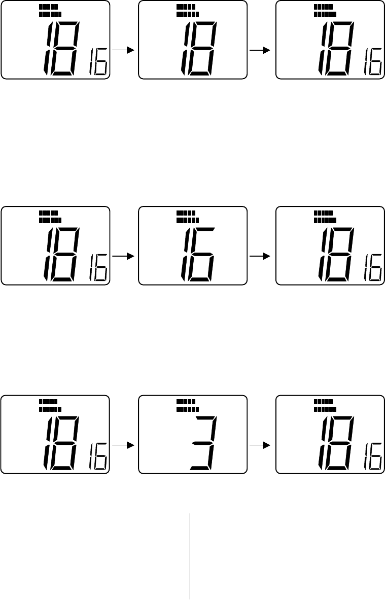
7) 16/9 Key
-. When 16/9 key is pressed and released, Alarm 1 is heard and Channel can be
changed as follows.
The current channel is Working CH---------------à Becomes Priority CH
The current channel is Weather CH---------------à Becomes Priority CH
The current channel is Priority CH ---------------à Becomes Working CH
-. When 16/9 key continues to be pressed for more than 2 seconds, Alerm 1 is heard and
priority CH can be toggled. When the private channnel is 16CH,it can be changed to
9CH and when the private channel is 9CH,it can be changed to 16CH.
8) PTT Key(Microphone)
-. When pressed,puts the radio into the transmit mode
If the current channel is Weather CH or the channel prohibitted from TX, Alerm 2 is
heard and PTT key cannot be used. If the PTT key is pressed continuously for over
five minutes,transmission is forcibly inhibited and Alarm 2 is heard until the PTT key
is released.
9) UP key(Microphone)
-. The UP key is used to move the channel numbers up(+1).
If the UP key is continuously pressed for over 0.5 seconds,the channel numbers can be
continuously up every 100msec.
10)DOWN key(Microphone)
-. The DOWN key is used to move the channel numbers down(+1)
If the DOWN key is continously pressed for over 0.5 seconds,the channel numbers
can be continueously down every 100msec.
11) 16/9 key(Microphone)
-. When 16/9 key is pressed and released, Alarm 1 is heard and Channel can be
changed as follows.
The current channel is Working CH---------------à Becomes Priority CH
The current channel is Weather CH---------------à Becomes Priority CH
The current channel is Priority CH ---------------à Becomes Working CH
-. When 16/9 key continues to be pressed for more than 2 seconds in Priority CH mode,
Alerm 1 is heard and priority CH can be toggled. When the private channnel is 16CH,it
can be changed to 9CH and when the private channel is 9CH,it can be changed to
16CH.
12) DISTRESS key
-. DISTRESS key is used to send a DSC Distress Call when pressed and held for 4
seconds.
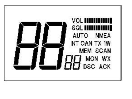
1.2.2 LCD Display
The items of LCD display on the Front panel are described as follows
1) DSC display: Will be displayed when DSC mode is entered.
2) WX display : Will be displayed when Weather CH is entered.
Will be displayed when Tri monitor mode is entered.
3) INT display : Will be displayed when International channels are programmed for
use. “INT” is not displayed when US or Canadian channels are
programmed for use.
4) CAN display: Will be displayed when Canadian channels are programmed for use.
“CAN” is not displayed when US or International channels are
programmed for use.
5) MEM display: Will be displayed when displayed CH is memory-registered.
Will blink at Scan Stand-by and be displayed at Memory Scan.
6) SCAN display: Will be displayed at Scan mode
Will blink at Scan at Scan mode and be displayed with “MEM” at
Memory Scan.
7) ACK display : Will be displayed at DSC mode when the response to individual calls
are received after DSC call is transmitted.
8) MON display: Will be displayed at Monitor mode
(Dual monitor or Triple monitor)
9) TX display : Will be displayed when transmitter power is detected at transmitter
mode.
10) 1 W display: Will be displayed when the transmitter circuits are providing 1 Watt
of power to the antenna. When the transmitter is supplying 25 Watt
to the antenna, “1 W” will be extinguished.
11)VOL, Bar
Graph display: The Vol. bar graph shows the level of volume of the audio output
to the speaker.
The volume means to be larger when the dot of the bar graph
become increased to the right.
12) SQL,AUTO : The Squelch bar graph shows the depth of squelch.
Bar graph “AUTO” will be displayed when Auto-Squelch is activate.
display The number of dot of SQL Bar graph will be increased when SQL
knob is turned to the right to make Squelch deeper.
(When SQL knob is furthermore turned to right from the
maximum squelch, the squelch becomes AUTO Squelch and
“AUTO” will be displayed.
13) NMEA display: will be displayed at all of the modes while valid NMEA data is
being received.
When NMEA data is invalid or is not received,”NMEA” is
extinguished.
Applicable data: GLL,GGA,RMA,RMC,APA,APB
14) Channel display: Will display channel number in use.
(Large) When Own Ship’s MMSI ID is entered,etc,Channel
display(Large) shows its situation.
15) Channel display: Will display Priority CH number in use.
(Small) When Own Ship’s MMSI ID is entered,etc, Channel
display(Small) shows its situation.
1.3 OPERATING PROCEDURES
1.3.1 Turning the Power On
1) Rotate the VOLUME knob clockwise to turn the radio on.
1.3.2 Setting the Volume
1) Rotate the VOLUME knob for the disired volume level.
1.3.3. Setting the Power Output
1) Simply press the “MON 1/25” key for two seconds to toggle between 1 Watt output
and 25 Watt output. When “1 WATT” is displayed,the output power is 1 Watt.
If “1 WATT” is extinguished, 25watts is being output. The choice of power output is
dependent upon the distance of transmission and transmitting conditions. In certain
US harbors and on certain channels, the FCC requires the power to be limited to
1 Watt. On these “required “ channels,the radio automatically selects 1 Watt power
output when the channel is selected.
1.3.4 Selecting the Channel
1) To select the appropriate channel, rotate CHANNEL SELECTION Knob clockwise /
counterclockwise or also press UP/DOWN key of the microphone.
2) The channels which are not set on the frequency mode are skipped .
3) When UP/DOWN key is continuously pressed for over 0.5 seconds,the channel is
continuously changed(+1 or – 1) every 100msec during pressing UP/DOWN key.
1.3.5 To select the frequency mode
1) The frequency mode(group) can be selected from US mode, International mode and
Canadian Mode.
The frequency mode can be shown on the LCD as follows.
USA frequency mode----------------------------à “INT” and “CAN” are eliminated
CANADIAN frequency mode------------------à “CAN” is displayed and “INT” is
eliminated.
INTERNATIONAL frequency mode----------à “INT” is displayed and “CAN” is
eliminated.
When WX/INT key is pressed and held for over 2 seconds, one frequency mode
can be changed to the other frequency mode and Alerm 1 is heard.:
For example:
When USA mode is in use,it can be changed to CANADIAN mode by doing above
operation.
When Canadian mode, it can bew changed to International mode. When
International mode,it can be changed to USA mode. The last changed frequency
mode can be memorized.
When the power is turned on,the last memorized frequency mode can be
used.(Channel number is16CH at that time.)
1.3.6 To Transmit
1) Press the Push-To-Talk switch(PTT switch) and speak into the microphone using a
clear normal voice.
2) If the current channel is Weather CH or the Tx prohibited channel, PTT switch cannot
be used and Audible beep sound 2 is heard.
3) RAY53 is designed to meet the new FCC Rules Part 80.203, which states,if the PTT
switch is pressed continuously for over five minutes,transmission is forcibly inhibited.
If this occurs,audible beep sound 2 will be heard until the PTT switch is released.
1.3.7 To select a Weather Channel
1) Simply press the WX/INT,then use Channel Selection Knob or UP/DOWN key to
select the desired Weather Channel from 0 to 9. When this mode is selected,the
transmitter is always inhibited.
2) When the Weather CH is finished by pressing WX/INT key,the last used Weather CH
number is memorized
3) When the power is re-turned on,the memorized Weather CH number can be
activate on the Weather CH mode.
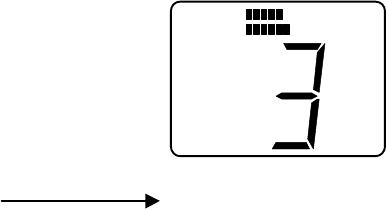
1.3.8 Priority Channel
1)When 16/9 is pressed and released, Alarm 1 is heard and Priority Channel is in use then
Channel Display(Small) shows “P” on the LCD.(“P” display means “Priority CH”.)
2) When 16/9 key is pressed and released again during “P” is diplayed, Alerm 1 is heard
and the channel will be returned to the privious Working CH. When the channel is
changed by UP/DOWN key during Priority CH is displayed, “P” display will be
eliminated and Workimg CH will be in use.
3) When 16/9 is continueously pressed for over 2 seconds, Alerm 1 is heard and Priority
channel can be changed either 16CH or 9CH.(When Priority CH is 16CH, it can be
changed to 9CH and when Priority CH is 9CH,it can be changed to 16CH.)
1.3.8 Channel Memory
1) The RAY53 has the capability of memorizing all US,International and Canadian
Channels. The channels memorized will be scanned in the Memory Scan mode.
2) Channel Memory: When SCAN/MEM key is pressed and held for over 3 seconds,the
audible beep sound 1 is heard and the selected current channel can
be put into memory.
When the displayed channel on the LCD is memorized, “MEM” is
displayed on the LCD.
Memory Clear : To press and hold for 3 seconds when the memory channel is
stored, the audible beep sound 1 is heard and the channel can be
cleared
When the displayed channel is not memorized,”MEM” is not
displayed on the LCD.
1.3.9 Scan Modes
The RAY53 is equipped with two types of scan options, All-scan and Memory Scan. How
these options are accessed is dependent upon whether there are any channels stored in
memory.
1) All-Scan mode
If no channels are stored in memory,when the SCAN/MEM key is pressed and
released, the audible beep sound 1 is heard and ”SCAN” will begin to flash on the LCD for
three seconds. If no other keys are pressed in these three seconds,the radio will begin
scanning all channels(except weather channels) as long as no signal is received. If a
signal is received,the scan will stop on the receiving channel. If the signal is lost for five
seconds, the radio will resume scanning. While the radio is scanning ALL-Scan,”SCAN” is
displayed on the LCD.
To cancel the scan mode,press the SCAN/MEM key while the radio is scanning.
2) Memory Scan mode
If one or more channels are stored in memory,when the SCAN/MEM key is pressed and
released, the audible beep sound 1 is heard and “SCAN” and “MEM” will begin to flash
simultaneously on the LCD for 3 seconds. If no other key is pressed in these three
seconds, the radio will begin scanning all channels currently in memory.(Begin Memory
scanning) As with All-Scan, If a signal is received,the scan will stop on the receiving
channel until the signal is lost for five seconds, the radio will resume scanning.
While the radio is scanning Memory Scan, “SCAN” and “MEM” are displayed on the LCD.
To cancel memory scan,press the SCAN/MEM key while the radio is scanning.
When SCAN/MEM key is pressed again during “MEM” flashing within these three
seconds, the audible beep sound 1 is heard and “SCAN” will flash on the LCD and the
radio will begin ALL Scan mode. “MEM” will disaprear from the LCD leaving only “SCAN”
flashing.
1.3.10 Monitor operations
1) The RAY53 is equiped with 2 types of monitor operations, Dual Watch opeartion and
Tri Watch operation.
Working CH and Priority CH can be monitored alternately in Dual Watch operation.
Working CH, Priority CH and Weather CH can be monitored by turns in Tri Watch
operation.
2)Dual Watch and Tri Watch can be changed each other by using WX/INT key.
When WX/INT key is pressed and released in the monitor mode, Alerm 1 is heard
and Dual Watch and Tri Watch can be changed each other alternately.
WX
MON
WX
Dual Monitor Tri Monitor
Dual Watch operation
-. “MON” is displayed on the LCD.
-. Working CH number is displayed at Channel Display(Large) on the LCD.
-. Priority CH(16CH or 9CH) number is displayed at Channel Display(Small) on the
LCD.
. If the signal of Working CH is detected, the Channel Display(Small) will be
extinguished and the monitor will stop temporarily. Then the Receiver will be done for
7 seconds.( Even if there is no carrier for these 7 seconds, the monitor will stop for 7
seconds.) After 7 seconds is passed,the radio will monitor Priority CH.
-. If the carrier of Private CH is detected , the Priority CH number is displayed at the
Channel Display(Large) and the Channel Display(Small) will be extinguished and the
monitor will stop temporarily.
Tri Watch operation
-. “MON” is displayed on the LCD.
-. Working CH number is displayed at Channel Display(Large) on the LCD.
-. Priority CH(16CH or 9CH) number is displayed at Channel Display(Small) on the
LCD.
NMEA
VOL
SQL
NMEA
VOL
SQL
M O N
NMEA
WX
VOL
SQL
M O N
-. “WX” is displayed on the LCD
-. If the carrier of Working CH is detected, the Channel Display(Small) will be
extinguished and the monitor will stop temporarily. Then the Receiver will be done
for 7 seconds.( Even if there is no carrier for thse 7 seconds, the monitor will stop for 7
seconds.) After 7 seconds is passed,the radio will monitor Priority CH.
-. If the carrier of Private CH is detected, the Priority CH number is displayed at the
Channel Display(Large) and the Channel Display(Small) will be extinguished and the
monitor will stop temporarily.
7 seconds has been passed after the carrier is eliminated, the radio will monitor
Weather CH.
-. If the carrier or the alert of Weather CH is detected, the monitor operation will stop
and Weather CH will become in use with “WX” flashing every 0.5 sec and Alerm 3 is
heard for 5 seconds.
The Variation by carrier detection during Monitor operation
Carrier Detection at Working CH
Carrier is detected 7 seconds is passed
at Working CH after the carrier is OFF
Carrier Detection at Priority CH
Carrier is detected 7 seconds is passed
at Priority CH after the carrier is OFF
Carrier Detection at Weather CH (Alert is received)
Carrier is detected Alert is not detected
NMEA
VOL
SQL
M O N
NMEA
VOL
SQL
M O N
NMEA
VOL
SQL
M O N
NMEA
VOL
SQL
M O N
NMEA
VOL
SQL
M O N
NMEA
VOL
SQL
M O N
NMEA
WX
VOL
SQL
M O N
NMEA
WX
VOL
SQ
L
M O N
NMEA
WX
VOL
SQL
M O N
at Weather CH
Alert is detected
"WX" flash
Exit Monitor mode
1.3.11 The key opeartion during the monitor operation.
-. When PTT key is pressed,the monitor will stop and the transmission will be done at
the stopped channel. While detecting the carrier of Weather CH or detecting Weather
Alert, the transmission will be done at Workimg CH.
NMEA
WX
VOL
SQL
Press PTT key
at Priority CH
Priority CH is transmitted
Press PTT key at Working CH
Press PTT key at Weather CH
Working CH is transmitted
-. When SCAN/MEM key , MON/1/25 key or UP/DOWN key is pressed, Alerm 1 is heard
and the monitor will stop and then Workimg CH will be in use.
Stop monitor mode
Switch to
Working CH
-. When 16/9 key is pressed, Alerm 1 is heard and Scan operation will stop and then Priority
CH will be in use.
Stop monitor mode
Switch to
Priority CH
NMEA
VOL
TX
SQL
NMEA
VOL
SQL
M O N
NMEA
VOL
SQL
NMEA
VOL
SQL
NMEA
VOL
SQL
M O N
NMEA
VOL
TX
SQL
NMEA
WX
VOL
SQL
M O N
-. Even if the Channel Selection knob is operated,there is no change.
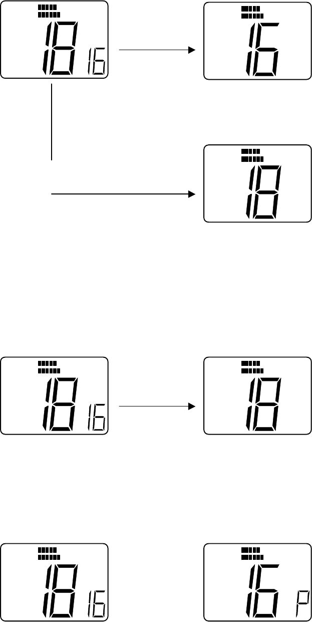
1.3.12 The operation for Weather Alert detection(Alert Tone : 1050 Hz)
Alert detection checks the output power from Alert detection IC as following timing.
100msec 10msec 25msec
0 2 4 6 8 10 11 12 13 14 15 16 17 18
-. When the alert is ready to be detected(when the carrier is detected), the detection
will start to be checked after 100msec.
-. The detection is checked 11 times per every 10msec and then the detection is
checked 8 times per every 25msec. If the alert is detected at all the checking points,
it means that Weather Alert can be detected.
The detection are checked with timing changed during total 300msec.
-. If none of detection is detected between 0 and 18 with the above timing, re-start at
first 100msec.
-. If the alerts are not detected at some of the above timing between 0 and 18,the
following scanning will be done.
When alert tone is detected at Tri Watch monitor, “WX” display flashes every
sec and Alarm 3 is heard for 5 seconds.
Alert tone is detected
"WX" flash and
Alarm 3 is heard
2. When alert tone is detected at Weather CH, “WX” display flashes every 0.5sec.
NM
EA
WX
VOL
SQL
M O N
NMEA
WX
VOL
SQL

(Alarm 3 is not heard)
Alert tone is detected
"WX" is flashing
NMEA
WX
VOL
SQL
NMEA
WX
VOL
SQL
The operation by any keys after alert detection.
-. When either PTT key,SCAN/MEM key or MON/1/25 key is pressed, Alarm 2 is
heard to prohibit keys from using.
-. When WX/INT key, 16/9 key or UP/DOWN key is pressed, “WX” display will be
eliminated and the key operation will be in use.
-. Even if the Channel Selection knob is operated,there are no changes.
1.3.13 DSC (Digital Selective Calling)
The DSC mode enables you to contact or be contacted by another vessel digitally,without
voice communications. DSC can be used to replace the normal routine of verbally contacting
another vessel on CH16,then proceeding to a working channel for further communications.
Your radio must be set to CH70 to transmit or receive DSC calls. The three DSC call modes
are described in the following section.
1) Own Ship’s ID Entry(Own Ship’s MMSI Entry)
To operate the RAY53 in the DSC mode,Own Ship’s ID must be registered in advance. The
registration procedure is as follows.
1. * If the former ID has been entered, Own Ship’s ID cannot be entered and Alarm 2 is
heard. There should be no MMSI number in the unit when shipped.
It is necessary for re-enter Own ship’s ID to delete the former ID by Own Ship’s ID
Clear.
*If there is no former ID, Alarm 1 is heard and Own Ship’s ID can be entered.
2. To enter DSC setting mode, press and hold the SCAN/MEM and WX/INT keys
simultaneously for 2 seconds.
----à “DSC” is displayed, which means the unit is in DSC mode.
----à “MEM” is displayed, which means OwnShip’s MMSI can be entered in DSC
mode.
3. MMSI number can be put by the following operation
-. “0” is displayed at Channel Display(Large) on the LCD and “1” is displayed at
Channel Display(Small) on the LCD.
Channel Display(Large) is representative the MMSI number itself and Channel
Display(Small) is representative of the position in the 9 digit.
-. When the Channel Selection knob is rotated, Channel Display(Large) shows the
MMSI number is increased/decreased as “0” base.( 0 to 9 can be selected)
-. MMSI number is selected by knob being rotated. When DSC key is pressed,
the audible beep sound 1 is heard and the selected number can be memorized.(“2” is
displayed at Channel Display(Small) on the LCD which means that 2nd(second) digit is
ready to be input. And the rest of the digits are entered in the same manner.
-. Once all of the digits have been entered, the unit will redisplay ID numbers every
1 second.
-. If the number was entered incorrectly, the customer perform the entry again by
pressing and releasing DSC key. At that time “0” is displayed at Channel
Display(Large) and “1” is displayed at Channel Display(Small).
-. If the number is entered correctly, the entered number becomes Own Ship’s
MMSI by pressing DSC key for 2 seconds and the audible beep sound 1 is heard,then
the DSC mode is exited and returned to Working CH.
4. Entry of number is done by Channel Selection knob. The number cannot be input by
UP/DOWN key on the Microphone.
The stored data can be memorized only by DSC key
The stored data cannot be memorized by the other key operations and cannot be done
when the power is turned off on the way.
5. The way to CLEAR Own ship’s ID No.
To turn the unit on with pressing and holding SCAN/MEM + 16/9 key simultaneously.
The audible beep sound 1 is heard and “CL” is displayed at Channel Display(Large).
2) Individual Ship’ Call”
1. “Individual Ship’s Call” specifies other Ship’s Number and the channel number.
Unless Own Ship’s MMSI ID is entered, Individual Ship’s Call cannot be used.
2. When SCAN/MEM key and WX/INT key are simultaneously pressed and
released, Individual Ship’s Call will be in use.
---à “DSC” is displayed on the LCD which means the unit is in DSC mode.
---à Channel 70 is displayed at Channel Display(Large)
(Programming for PLL data of 70CH.)
---à “In” is displayed at Channel Display(Small) which means the unit is in
Individual Ship’s Call mode.
3. When SCAN/MEM key (“DSC” key) is pressed and released, the audible beep sound 1
is heard and the other ship’s Number can be set.
-. “0” is displayed at Channel Display(Large) on the LCD and “1” is displayed at
Channel Display(Small) on the LCD.
Channel Display(Large) is representative of the MMSI number itself and Channel
Display(Small) is representative of the position in the 9 digit.
-. When the Channel Selection knob is rotated, Channel Display(Large) shows the
MMSI number is increased/decreased as “0” base.( 0 to 9 can be selected)
-. MMSI number is selected by knob being rotated. When SCAN/MEM key(DSC key) is
pressed, the audible beep sound 1 is heard and the selected number can be
memorized.(“2” is displayed at Channel Display on the LCD, which means that 2nd
(second) digit, is ready to be input. And the rest of the digits are entered in the same
manner.
-. Once all of the digits have been entered, the unit will redisplay ID numbers
every 1 second.
-. If the number was entered incorrectly, the customer can perform the entry again by
pressing and releasing SCAN/MEM key(DSC key). At that time “0” is displayed at
Channel Display(Large) and “1” is displayed at Channel Display(Small).
4. Entry of number is done by Channel Selection knob. UP/DOWN key on the
Microphone does not enter the number.
5. If the number is entered correctly, the entered number becomes “Other Ship’s
Number” by pressing SCAN/MEM key(DSC key) for 2 seconds and the audible beep
sound 1 is heard.
The stored data can be memorized only by SCAN/MEM key(DSC key).
The stored data cannot be memorized by the other key operations and cannot be done
when the power is turned off on the way.
6. After entry of “Other Ship’s number”, Other Ship’s Channel Number is ready to be
entered.
---à ”--- ---“ is displayed at Channel Display(Large) which means Channel number
is ready to be entered.
---à “W” is displayed at Channel Display(Small) which means the working channel
is to be selected.
6’ If the operator would like to resistor Other ship’s MMSI No.only without attempt of
transmission, the last used(before registration of MMSI) CH will be displayed by
pressing 16/9 key at this stage.
7. -. Working Channel can be selected by rotating Channel Selection knob.
-. When SCAN/MEM key(“DSC” key) is pressed and released, the audible beep sound
is heard and the selected number can be memorized as Working Channel number.
8. If the operator would like to resistor Other ship’s MMSI No.only without attempt of
transmission, the last used(before registration of MMSI) CH will be displayed by pressing
16/9 key at
9. After entry of “Channel number”, “Individual Ship’s Call” is ready to transmit.
----à “TX” is flashing on the display(Instruction to be ready to transmit)
----à Channel 70 is displayed at Channel Display(Large)
(Programming for PLL data of 70CH.)
----à “In” is displayed at Channel Display(Small) (Instruction for Individual Ship’s
Call)
-. While “TX” is flashing,Individual Ship’s Call can transmit at 70CH by pressing
PTT key.
-. After transmission, when an acknowledgement from the target ship is
received, the audible beep sound is heard and “ACK” is displayed on the LCD.
-. When 2 seconds is passed after receipt of acknowledge, the unit will switch to
selected Channel number and “DSC” mode will be exited.
When DSC mode is exited,”DSC” and “ACK” will be eliminated.
Channel Display(Large) displays the selected Channel number.
Channel Display(Small) is eliminated.
-. If an acknowledge from the target ship is not received, “Individual Ship’s Call” at
70CH is still remaining in use.
(“Individual Ship’s Call” can transmit again by pressing PTT key)
10. The way to CLEAR Other ship’s MMSI No.
There are two ways to clear Other Ship’s MMSI No.
1) To turn the unit on with pressing and holding SCAN/MEM key simultaneously.
Alarm 1 is heard and “CL” is displayed at Channel Display(Large).
Or
2) To turn the radio on with pressing and holding SCAN/MEM key and 16/9 key
Simultaneously. Alarm 1 is heard and “CL” is displayed at Channel Display(Large).
(Own Ship’s ID No. is also CLEAR by doing this operation.)
3) Other ship’s MMSI previously entered.
When the other ship MMSI number has been entered,the operator does not have to
register the other ship’s MMSI number by doing the following procedure.
1. Press SCAN/MEM key and WX/INT key simultaneously
2. Then “MEM”, “DSC”, “70” (Large channel display), “In”(Small channel display) are
displayed on LCD.
-“MEM” means that the other ship’s MMSI number has been registered.
-.”DSC” means that the unit is in DSC mode.
-.”In” means that the unit is in DSC mode.
3. Press and release DSC key.
4. “MEM”,”DSC” “0”(Large channel display) and “1”(Small channel display) are displayed on
the LCD.
5. Press and release MON key if you would like to check the MMSI number.
6. The MMSI number of each digit is displayed every 1 sec from 1st digit to 9th digit.
MMSI number itself is displayed on the Large Channel Display.
The number of digit is displayed on the Small Channel Display.
7. After all MMSI number(total 9 digits) are displayed, to press DSC key for 2 second,
the LCD displays “DSC”, “ --- ---“,(Large Channel Display) and “w”(Small Channel
Display) which means the unit is ready and waiting for input of Calling CH .
5’ Press and release WX/INT key if you do not have to check the MMSI number again ,
6’ the LCD displays “DSC”, “ --- ---“,(Large Channel Display) and “w”(Small Channel
Display) which means the unit is ready and waiting for input of Calling CH .
8. (If you would like to enter the different Other Ship’s MMSI number manually),
1. To rotate channel selection knob from the stage of the above 4(“MEM”,”DSC”,”0” and
“1”) ,then the different other ship’s MMSI number can be set. The LCD displays “DSC” ,
“3”(Large Channel display) and “1” (Small Channel display) which means that the number
of 1st digit is 3.
2. To press and release DSC key for confirmation,Alerm 1 is heard and the MMSI number of
2nd digit will be ready to be input. “MEM”, “DSC”,”0”(Large Channel Display) and
“2”(Small Channel display) are displayed on the LCD. To rotate Channel Selection
Knob,the MMSI number of 2nd digit is selected.
3. The rest of the digits are entered in the same manner.
4. Once all of the digits have been entered,the unit re-display MMSI Number every 1 sec
from 1st digit to 9th digit. When the operator confirmed MMSI number, “DSC”
“--- ---“ and “w” are displayed on the LCD by pressing and holding DSC key for 2
seconds.
If the operator would like to double check the MMSI number again or to change the MMSI
number, the LCD displays “MEM”,”DSC”,”0” and “1” by pressing and releasing DSC key.
4) Receiving Individual Ship’s Call Response
1. The receivable Channel is only 70CH. It can be done even in working CH, Monitor
mode and Scan mode.
2. When the unit receive the signal, the unit will become automatically “DSC” mode.
If the received signal is for the unit itself,the unit will respond the signal.
If the received signal is not for the unit itself, the unit will not respond and Monitor
Mode or Scan mode will continue to be in use.
3. The operation when the received signal is for the unit itself.
When the unit receives “Individual Ship’s Call” at 70CH, Alarm tone will sound.
----à “DSC” is displayed which means the unit is in DSC mode.
----à Channel Display(Large) displays 70CH.
----à “In” is flashing at Channel Display(Small) which means the unit is ready to
receive Individual Ship’s Call.
----à “TX” is flashing, which means the unit is ready to receive Individual Ship’s Call.
4. To transmit the response by pressing PTT key.
After transmission,the unit will switch to instructed Channel number and DSC
mode will be exited.
----àWhen DSC mode is exited, “DSC” is eliminated.
----àChannel Display(Large) display the selected Channel number.
----àChannel Display(Small) is eliminated.
5. The transmitter/receiver can be done at the selected channel number.
5) “All Ship’s Call”
1. “All Ship’s Call” does not specify the other ship.
“All Ship’s Call is general call to any ship to initiate contact on channel 16.
Unless “Own Ship’s ID” is entered,”All Ship’s Call” cannot be done.
2. When SCAN/MEM key and WX/INT key are simultaneously pressed and
released, “All Ship’s Call” will be in use.
----à “DSC” is displayed on the LCD which means the unit is in DSC mode.
----à Channel 70 is displayed at Channel Display(Large)
(Programming for PLL data of 70CH.)
----à “In” is displayed at Channel Display(Small) which means the unit is in
Individual Ship’s Call mode.
3. “All Ship’s Call” can be selected by rotating Channel Selection Knob.
Channel Display(Small) displays “AS”.
Whether “Individual Ship’s Call” or “All Ship’s Call” can be selected by Channel
Selection Knob.
When “Individual Ship’s Call” is selected, Channel Display(Small) displays “In”.
When “All Ship’s Call” is selected, Channel Display(Small) displays “AS”.
5. After selection of All Ship’s Call”,when SCAN/MEM key(“DSC” key) is pressed,
the audible beep sound 1 is heard and the unit is ready to transmit “All Ship’s Call”
----à “TX” is flashing on the LCD which means that Transmission is ready.
----à Channel 70 is displayed at Channel Display(Large).
----à “AS” is displayed at Channel Display(Small) which means that the unit is in
All ship’s Call mode.
6. While “TX” is flashing, All Ship’s Call can transmit at 70CH by pressing
and releasing PTT key. Transmitter output power is limited to 1W.
7. After transmission,the unit will switch to 16CH of Working CH and DSC mode will
be exited.
When DSC mode is exited, ”DSC” will be eliminated.
Channel Display(Large) displays 16CH of Working CH..
Channel Display(Small) is eliminated.
(“Individual Ship’s Call” can transmit again by pressing PTT key)
5) Receiving All Ship’s Call
The receivable Channel is only 70CH. It can be done even in working CH, Monitor
mode and Scan mode.
When the unit receive the signal, the unit will become automatically “DSC” mode
1. When the unit receives “All Ship’s Call” at 70CH, Alarm tone will sound.
----à “DSC” is displayed which means the unit is in DSC mode.
----à Channel Display(Large) displays 70CH.
----à “As” is flashing at Channel Display(Small) which means the unit is ready to
receive All Ship’s Call.
2. After the unit received “All Ship’s Call”, when SCAN/MEM key(“DSC” key) is
pressed, the audible beep sound 1 is heard and the unit will switch to the 16CH of
Working CH and then “DSC” mode will be exited.
----à When “DSC” mode is exited, “DSC” is eliminated from the LCD.
----à Channel display(Large) displays 16CH of Working CH.
----à Channel Display(Small) is eliminated.
6) “ Distress Call”
The “Distress Call” is to be initiated by pressing and holding the “DISTRESS” key
on the rear of the microphone for 4 seconds.The Distress call has highest priority of
all the operations.
Unless Own Ship’s MMSI ID is entered, Distress Call is not available.
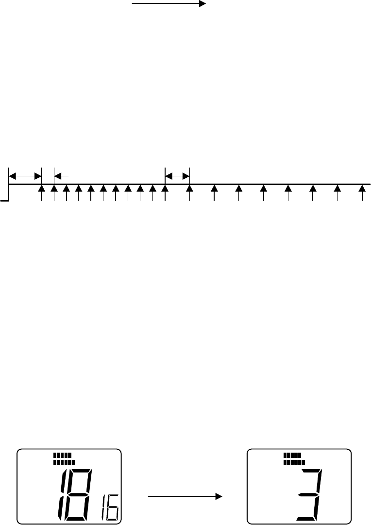
1. When Distress key is continuously pressed, “Distress Call” can start to operate.
----à “DSC” is displayed which means the unit is in DSC mode.
----à Channel Display(Large) displays Counts down time(4,3,2,1).
Counts down will be shown every 1 second on Channel Display(Large)
----à “d” is displayed at Channel Display(Small)
2. “Distress” key has to be pressed continuously for over 4 seconds.
While Distress key is being pressed, Channel Display(Large) is showing Count
down times like 4à3à2à1.
If “Distress” key is released on the way before 4 seconds, “Distress Call”
operation will be cancelled.
3. After Count down is finished,”Distress Call” can start to be transmitted.
----à Channel Display(Large) displays 70CH.
----à “d ” is displayed at Channel Display(Small) which means the unit is in
Distress Call mode.
----à Distress signal can be automatically transmitted.( “TX” is displayed on the
LCD during transmitting.)
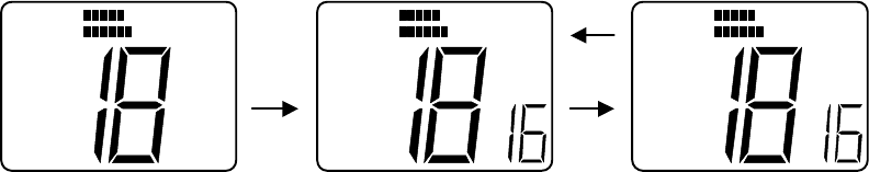
4. After transmitting Distress signal,the unit will wait for an acknowledgement from
the other ship.
----à Channel Display(Large) displays 70CH.
----à Channel Display(Small) displays “16” which means the channel after
receipt of an acknowledgement will be 16CH.
----à “TX” will be eliminated.
5. If the unit does not receive any acknowledgement from the other ships for Distress
Call even after Distress Call was transmitted, Distress signal can be
transmitted automatically randomly every 3.5 – 4 sec until receiving
acknowledgement from the others.
When the acknowledgement is received,the automatic transmission will not be
necessary.
6. Once an acknowledgement is received from the other ship, Alerm tone will sound
and “Distress Call” mode will be exited and the unit automatically select 16CH.
----à”ACK” is displayed by receiving acknowledgement. (“ACK” will be eliminated
after 16CH is selected.)
----à”DSC” is eliminated.
----à Channel Display(Large) displays 16CH of Working CH.
----à Channel Display(Small) is eliminated.
7) Receiving “Distress Call”
The receivable Channel is only 70CH. It can be done even in working CH, Monitor
mode and Scan mode.
When the unit receive the signal, the unit will become automatically “DSC” mode
(1)When the unit receives “Distress Call” at 70CH.
----à “DSC” is displayed which means the unit is in DSC mode.
----à Channel Display(Large) displays 70CH.
----à “d ” is flashing at Channel Display(Small) which means the unit is ready to
receive Distress Call.
After the unit received “Distress Call”, when “DSC” key is pressed and released,
Alarm 1 is heard and the unit will switch to the 16CH of Working CH and then
“DSC” mode will be exited.
---à When “DSC” mode is exited, “DSC” is eliminated from the LCD.
---à Channel Display(Small) is eliminated3. DSC Watch mode can be activate by doing
following operat.
8) DSC WATCH Mode/ON OFF operation
1. DSC WATCH operation is defined that the radio is searching for CH70(DSC Channel) in
Receiving Working Channel , Scan Operation mode, and Monitor Operation mode.
2. DSC Watch operation can be selected with ON/OFF by panel operation. DSC WATCH
should be OFF when the unit is ex-factoried.
1) Press and hold SCAN/MEM key and WX/INT key simultaneously for 2 seconds.
2) “DSC” , “70” (Large CH display) and ‘In”(Small CH display) are displayed on the LCD.
The unit is in the selection mode for Individual Ship’s Call.
3) Rotate Channel Selection Knob to the right.
4) “DSC” , “70”(Large CH display) and “As”(Small CH display) are displayed on the
LCD. The unit is in the selection mode for All Ship’s Call.
5) Rotate Channel Selection Knob to the right.
6) “DSC”, “70”(Large CH display) , and “0F”(Small CH display) are displayed on the
LCD. At this stage, DSC Watch mode can be selected. “0F” on the Small CH
display means that DSC Watch is OFF.
Further to rotate CH selection Knob to the right,the unit repeat to be displayed from
the above 2) . The display will be done as 6)à 2) à 4) à 6).
To rotate Channel Selection Knob to the left, the unit will be displayed back to the
Above 4). The display will be done as 6) à 4) à 2) à 6).
7) By pressing SCAN/MEM key, DSC Watch mode can be selected either ON or OFF.
8) To press SCAN/MEM key and WX/INT key simultanously, the unit return to the last
Used display before the above 1) display.
9) When Power is re-activate on, the unit will start in the mode last used.(On or OFF).

2.
SPECIFICATIONS
Transmitter
Channels All available US,International and Canada VHF Marine band
Frequency Stability +/- 10PPM(+/- 0.001%)
(-20° C ° C
Frequency Range 156.025 to 157.425MHz
Channel Spacing 25 kHz Increments
Power Output 25 Watts switchable to 1 Watt into 50 Ohms at 13.6 VDC
Modulation Frequency modulated 16F3
(+/-4.5kHz at 1000Hz)
Modulation Audio Response Shall not vary +1/-3 dB from true 6 dB pre-emphasis from 300
to 2500Hz, reference 1000Hz. Audio frequencies 3-20 kHz
shall be attenuated(at 1 kHz by 60 log f/3 dB. Above 20kHz
by 50dB)
FM Hum & Noise level Less than –40dB below audio
Audio Distortion Less than 10% at 1kHz for 3kHz deviation
Spurious & Homonic Attenuated at least 43+10log Po(below ratd radiated carrier
Emissions power) per FCC Rules Part 2 & 80
Antenna Impedance 50 Ohm
Transmitter Protection Shall survive open or short circuit of anttena system without
damage(10 min.test)
Receiver
Channels All available US,International,Canada VHF Marine Band

Frequency Range 156.025 to 163.275 MHz in 25 kHz increments
Frequency Stability +/- 10 PPM(+/- 0.001%) from -20° °
Usable Sensitivity 0.3µV for 12dB(SINAD)
Squelch Sensitivity 0.2µV or better
Threshold 1.0µ full squelch
Adjacent CH Rejection 70dB
Spurious Image Rejection 70dB
Intermodulation Rejection 70dB
Audio Output 2 Watt or more at 10% or less distortion into 8 Ohm
load(INTERNAL)
Hum & Noise in Audio Less than –40dB
Operating Requirement
Input Voltage 13.6 VDC +/- 15%(11.6 to 15.6 VDC)
Current Required Less than 5.8 amp at 25 Watts
Transmit Less than 1.5 amp at 1 Watt
Operating Temperature -20 °C to +50°C
Duty Cycle Continuous, 80% receive, 20% transmit
(max 10 min, @25° C )
Humidity 100% at 50°C for 8 hours
Radio Dimensions
Height 55 mm(2.17 inches)
Width 145mm(5.7 inches)
Depth 160mm(6.3 inches)
Weight Approx. 868g
3. TECHNICAL DESCRIPTION
10.1 General
The RAY53 can be considered as consisting of two major sections.
-. The control section(consisting of the front panel controls ,LCD display,and
CPU
-. The transmitter/Receiver/PLL section.
10.2 The Control Section
. The heart of the control section is the CPU,which is IC201 located on the
CNTL PCB. The CPU controls all of the following items:
-. Controls the Squelch circuit by detecting a busy signal from the 2nd IF
circuit IC3 on the RF PCB.
-. Generates a beep tone when a key is activated on the keyboard.
-. Mutes the transmitter modulation circuit when receiving.
-. Controls the output power of the transmitter High/Low.
-. Controls the dividing ratio N of the PLL circuit.
-. Switches On/Off the transmitter power.
-. Mutes AF audio.
-. Detects a weather alert signal(when in Monitor Mode)
-. Controls the LCD display.
3. 3 The transmitter/Receiver/PLL Sections
In reading through the following circuit descriptions, it may be helpful to
refer to Block Diagram of the TX/RX/PLL circuits.
10.3 1. PLL(Phase Lock Loop) Circuit
PLL circuit of this radio is PLL IC(IC2) and is composed of VCO circuit which is for
Transmitter and for Receiver independently. PLL IC(IC2) generates the setting
frequency based on the control data of CPU(IC201).
The reference oscillating frequency of the PLL circuit is 21.25MHz and is consisting of
crystal resonator X1 and IC2. This oscillating frequency 21.25MHz is divided into 1/850
to make 25KHz-reference frequency.
Transmit frequency is generated on the Inductor and Capacitor circuit with connected
to IC2 pin 4,5.
The frequency control voltage, which is output from IC2 pin 7, will be input into Variable
Capacitance Diode(D6) on Inductor and Capacitor circuit.
The receiver local frequency is generated on the Inductor and Capacitance circuit with
connected to IC2 pin 20, 21.
The frequency control voltage, which is output from IC2 pin 18, will be input into
Variable Capacitance Diode(D5) composed on
The oscillating frequency 21.25MHz which is output from IC2 pin 11 will be used for the
second local frequency of Receiver and it will be input into IF IC(IC2) pin 1.
10.4 Transmitting Circuit Operation
3.4.1 Microphone Amplifier Circuit:
Voice signal from the mocrophone goes through pre-emphasis circuit consisting of
C147 ,R104 and is amplified in MIC AMP IC8(A).
Pre-emphasis can be output by Diode(D10). The level of the signal is limited by D7
and adjusted in the VR4.
Limiter output is amplified by IC8(B),then it goes through the active 4-stage LPF
consisting of IC8(C) and IC8(D). 4-stage LPF output goes into Variable Capacitance
Diode(D7) and then it makes Frequency modulation.
3.4.2 Transmit Frequency Power Amplifier Circuit
RF signal from the PLL IC(IC2) pin 1 goes through the 10dB attenuator consisting of
R37,R38,R39 and will be amplified by Q11. Output from Q11 will amplify drive power
necessary for the Q4 and Q3. power module(IC5) will be amplified and the RF signal
will be output to the antenna switching circuit. 4-stage LPF consisting of L21 and
L1-L3 is used to improve the level of Transmission Spurious Emission. RF output
from the power module(IC5) can be changed by changing the voltage of IC5 pin2.
3.4.3 APC Circuit
Diode D4 is monitoring a part of the power module’s(IC5) output. The monitoring
signal will be output to IC5 via switching transistor Q8 and display the “TX ON” and
the LCD.
The output voltage from IC5 controls the RF power to keep the RF output at a
constant level.
3.4.4 DSC Signal Treatment
In DSC mode at CH70,a sequence signal from CPU is input to MODEM IC(IC11) and
converted to an analog signal. As a MODEM TX signal,this signal switches the analog
switch(Q20) from microphone input position to DSC position. Then DSC signal is sent
out to the transmitter microphone amplifier.
If NMEA information are input to P501 connector through GPS or other devices
connected to it,these information are taken into CPU through photo-coupler of Q22
and can be transmitted with DSC to provide information such as position and time.
3.5 RECEIVER CIRCUIT
3.5.1 Antenna Switching Circuit
A signal received at the antenna connector J501 goes to high frequency amplifier circuit
via 4-stage low pass filter consisting of coils L1-L3 and L21.
3.5.2 High Frequency Amplifier Circuit
RF signal goes to the 1st mixer circuit through 2-stage BPF(consisting of coil L5,6) and
will be high frequency amplified by Q1 and then 3-stage BPF(consisting of L8,L10,and
T3) . The 1st image spurious frequency will be rejected to the adequate level in the
5-stage BPF inside the high frequency amplifier circuit.
3.5.3 1st Intermediate Frequency Amplifier Circuit.
A double balanced mixer(DBM) of IC1 is used for 1st mixer of Receiver.
RF signal from RF Amplifier circuit input to IC1 pin 6. Receiver local frequency input from
PLL IC(IC2) pin 20 to IC1 pin3 and then converts the frequency.
The converted 1st IF signal(the frequency of 1st IF is 21.7MHz) goes through 1-stage
crystal filter(F1) and is amplified in transistor(Q2)
3.5.4 2nd Intermediate Frequency Circuit
The 1st IF signal is added to IC3 and converted to 2nd IF signal. The 2nd IF signal goes
through F2 and amplified in the IC3 and then through discriminator CD1 and the
demodulated AF signal is output from IC3.
3.5.5 Low Frequency Circuit
The AF signal demodulated in the IC3 goes through the de-emphasis circuit consisting of
operational amplifier IC4(A) and R127 and C45. A 3 stage active HPF consisting of
IC4(B) ,C48,C49 C50,R23,R24 and R25 is used to reject AF signal below 300Hz. The AF
signal from the 3-stage HPF goes through AF Volume VR301 and is input to the speaker
amplifier circuit IC9.
3.5.6 Audio Muting Circuit
The Q18 to mute the audio is controlled by input of squelch’s BUSY signal and the
mute output of the CPU(IC201).
3.5.7 WX Alert Detection
The tone selector IC10 detects the 1050Hz alert tine if it is contained in the
re-modulated AF and WX alert tone will be output from the speaker.
3.5.8 DSC Signal Treatment
If the re-modulated signal arriving is a DSC signal, it is input to MODEM IC(IC11) as an
RX MODEM signal, and converted to digital signal. Undergoing the treatment in the CPU
circuit, this digital signal changes the operation state to DSC mode.
4. ALIGNMENT for RAY53
4.1 PLL Adjustment(Receiver)
1.1 Connect the power supply(13.6V, 10) to the power line.
1.2 Set the radio on CH16(156.800MHz) and set it to Receiver mode.
1.3 Connect the reed terminal of a digital voltmeter or high impedance tester to Test
point(TP2) on RF PCB and set it to DC voltage range.
1.4 Adjust variable coil (T1) in the RF PCB(in the VCO shield case) and set the DC
voltage to 1.3V+/-0.1V.
4.2 PLL Adjustment(Transmitter)
Connect the power supply (13.6V,10A) to the power line.
Connect RF Power Meter(40W 50 ohm, 150-200MHz) to antenna connector.
Set the radio on CH16(156.800MHz) and set it to Transmitter mode.
Connect the reed terminal of a digital voltmeter or high impedance tester to Test
point(TP3) on RF PCB and set it to DC voltage range.
Adjust variable coil (T2) in the RF PCB(in the VCO shield case) and set the DC voltage to
2.0V+/-0.1V.
4.3. Frequency Adjustment(Transmitter)
4.3.1 Connect the power supply (13.6V,10A) to the power line.
4.3.2 Connect RF Power Meter(40W 50 ohm, 150-200MHz) to antenna connector.
Use Coupler in order to divide the transmitter output power and then connect to
frequency counter.
4.3.3 Set the radio on CH16(156.800MHz) and set it to Transmitter mode.
4.3.4 Adjust Trimmer Capacitor(TC1) in the RF PCB(in the VCO shield case) and set
the Frequency Counter to 156800.000Hz+/-100Hz.
4.4 Modulation Adjustment(Transmitter)
4.4.1 Connect the power supply (13.6V,10A) to the power line.
4.4.2 Connect RF Power Meter(40W 50 ohm, 150-200MHz) to antenna connector. Use
Coupler in order to divide the transmitter output power and then connects to FM
linear detector.
4.3.3 Connect the audio oscillator and PTT test Assy to Connector (J203) No.1 pin in
CNTL PCB. Set the audio oscillator to –18dBm and set the frequency to 1KHz
And then set it to transmitter mode.
4.4.4 Adjust Variable Resistor(VR4) in the RF PCB to set the deviation displayed on FM
linear detector to 4.2kHz+/-0.1kHz.
4.4.5 Set the audio oscillator to –38dBm and set the frequency to 1kHz. Confirm that the
deviation on FM linear detector should be 3.0kHz+/-0.5kHz.
4.5 Output Power Adjustment(Transmitter)
4.5.1 Connect the power supply (13.6V 10A) to the power line.and connect Power
Meter(40W, 50 ohm, 150-200MHz) to antenna connector.
4.5.2 Set the radio on CH 16(156.800MHz) and to be transmitter mode at Low power
mode.
4.5.3 Adjust the output power to 1.0W+/-0.1W by Variable Resistor (VR2) on the RF PCB.
4.5.4 Change the transmitter output selector Switch into Hi Power mode.
4.5.5 Adjust the output power to 2.5W +/-1W by Variable Resistor(VR3) on the RF PCB.
4.6 RF Sensitivity Adjustment(Receiver)
4.6.1 Connect a RF signal generator to the antenna connector and a SINAD meter to
the External speaker line.
4.6.2 Select the Weather Channel .
4.6.3 Set RF generator as follows:
Frequency : 163.275 MHz.
Modulation: 1.0 kHz
Deviation : 3.0kHz
4.6.4 Adjust T3 on RF board and make the best of SINAD sensitivity
5. ELECTRICAL CONNECTIONS
5.1 DC Power, External Speaker Connections and NMEA Input
The 6 feet long power cable assembly consists of the DC power cable and the
external speaker cable. The DC power cable is composed of RED(+) and
BLACK(-) wires, and the external speaker cable has YELLOW(+) and
GREEN THICK(-) wires and NMEA Input has GREEN THIN(+) and BROWN(-). The
RED(+) wire with an in-line fuse(10 amps.) and the BLACK(-) wire of the 6 pin
connector cable are used for connecting the RAY53 to the ship’s 13.6 VDC power
system.
In most cases this length should be adequate enough to reach the DC power
source.
If additional wire length is required,the cable can be extended by adding more
cable as necessary. However,for power cable runs longer than 15 feet,larger
wire diameter size should be used to prevent voltage line loss.
Your RAY53 radio should be connected to the nearest primary source of
ship’s DC power. A typical source may be a circuit breaker on the power
panel or a fuse block near the unit. When connecting to either of these
sources, the circuit breaker or other in-line fuse should be rated at 10 amps.
It is recommended that lugs be used to connect the power cable to the DC
supply and the lug connections should be both crimped and soldered. This is
very important in order to insure adequate currect draw to the equipment.
intermittent operation may result if an insufficient connection is made to the
power source. the connection terminal should be clean, with no sigh of
corrosion.
The RED(+) wire is connected to the positive terminal of the power source or
battery. The BLACK(-) wire is connected to the negative(ground) of the power
source or battery. Should the power connections be inadvertently reversed,the
10 amp.in-line fuse located in the RED(+) wire will open. Check the input
power leads for correct polarity with a VOM(volt/ohm meter),reconnect the
leads observing correct polarity,and replace the fuse. Use the same rate and
type fuse.
-The RAY53 accepts NMEA 0183 data from a GPS or Loran navigator to provide
Lat/Lon position information that is transmit during DSC Distress Call mode. The
NMEA sentences that could provide positional data,by order of priority are:
GGA.RMC,RMA,and GLL.
5.2 Antenna Connections
The coaxial cable to your VHF antenna is intended to be connected to the antenna
jack on the rear panel using a PL259 VHF type connector. The antenna cable may be
cut to the required length at installation. If a longer cable length is required, RG-58 50
ohm coaxial cable or equivalent cable may be used for runs up to a maximum of 50
feet. If the distance required is even greater,then we recommend using low loss
RG-213 or equivalent cable for the entire run in order to avoid excessive losses in
power output.
If the antenna RF connector is likely to be exposed to the marine environment, a
protective coating of grease(similar to Dow Corning DC-4) can be applied to the
connetor before connecting it to the radio. Any other extensions or adapters in the
cable run should also be protected by silicon grease and then wrapped with a
waterproofing tape.
5.3 Antenna Mouting Suggestions
The best radio in the world is useless without a good antenna location. Mounting the
VHF antenna properly is very important because it will directly affect the performance
of your VHF radio. A standard VHF antenna which is designed to use aboard boats
should be used.
-. Since VHF transmission are essentially Line-of-Sight,mount the antenna at the
highest possible location on the vessel and free of obstruction in order to
obtain maximum range.
-. Use an antenna with highest possible gain characteristics.
-. If you must extend the length of the coaxial cable between the antenna and the
Radio, use a coaxial cable designed for the least amount of power loss over

the entire cable length.
-. Keep the coaxial cable between the radio and antenna as short as possible.
5.4 Grounding
While special grounding is not generally required for VHF radiotelephone
installations, it is good marine practice to properly ground all electronic equipment to
the ship’s ground system. The RAY53 can be connected to ground by attaching a
wire to one of the screws on the unit’s rear panel and then to the nearest ship’s
ground connection point. The recommended wire to be used or such grounding is
#10 AWG.
RAY53’s cabinet was specially designed and die-cast from aluminum to insure
maximum noise rejection from external sources
USA Frequency DATA
CH
TX Frequency
RX
Frequency PWR
CH
TX Frequency
RX
Frequency PWR
1
1
56.050
156.050
73
156.675
156.675
2
74
156.725
156.725
3
156.150
156.150
75
156.775
1
4
76
156.825
1
5
156.250
156.250
77
156.875
156.875
3
6
156.300
156.300
78
156.925
156.925
7
156.350
156.
350
79
156.975
156.975

8
156.400
156.400
80
157.025
157.025
9
156.450
156.450
81
157.075
157.075
10
156.500
156.500
82
157.125
157.125
11
156.550
156.550
83
157.175
157.175
12
156.600
156.600
84
157
.225
161.825
13
156.650
156.650
2
85
157.275
161.875
14
156.700
156.700
86
157.325
161.925
15
156.750
1
87
157.375
161.975
16
156.800
156.800
88
157.425
157.425
17
156.850
156.850
3
18
156.900
15
6.900
19
156.950
156.950
WX Frequency DATA
20
157.000
157.000
21
157.050
157.050
CH
RX Frequency
22
157.100
157.100
0
163.275
23
157.150
157.150
1
162.550
24
157.200
161.800
2
162.400
25
157.250
161.850
3
162.475
26
157.300
161.900
4
162.425
27
157.350
161.950
5
162.450
28
157.400
162.000
6
162.500
60
7
162.525
61
156.075
156.075
8
161.650
62
9
161.775
63
156.1
75
156.175
64
156.225
156.225
65
156.275
156.275
66
156.325
156.325
67
156.375
156.375
2
68
156.425
156.425
69
156.475
156.475
70
156.525
156.525
4
71
156.575
1
56.575
72
156.625
156.625
INT Frequency DATA
CH
TX Frequency
RX
Frequency PWR
CH TX Frequency
RX Frequency
PWR
1
156.050
160.650
73
156.675
156.675
2
156.100
160.700
74
156.725
156.
725
3
156.150
160.750
75
156.775
1
4
156.200
160.800
76
156.825
1
5
156.250
160.850
77
156.875
156.875
3
6
156.300
156.300
78
156.925
156.875
7
156.350
160.950
79
156.975
156.875
8
156.400
156.400
80 1
57.025
156.875
9
156.450
156.450
81
157.075
156.875

10
156.500
156.500
82
157.125
156.875
11
156.550
156.550
83
157.175
156.875
12
156.600
156.600
84
157.225
156.875
13
156.650
156.650
2
85
157.275
156.875
14
156.700
156.700
86
157.325
156.875
15
156.750
1
87
157.375
156.875
16
156.800
156.800
88
157.425
156.875
17
156.850
156.850
3
18
156.900
161.500
19
156.950
161.550
20
157.000
161.600
21
157.050
161.650
22
157.100
161.700
23
157.150
161.750
24
157.200
161.800
25
157.250
161.850
26
157.300
161.900
27
157.350
161.950
28
157.400
162.000
60
156.02
5
160.625
61
156.075
160.675
62
156.125
160.725
63
156.175
160.775
64
156.225
160.825
65
156.275
160.875
66
156.325
160.925
67
156.375
156.375
2
68
156.425
156.425
69
156.475
156.475
70
156.525
156.525
4
71
156.575
156.575
72
156.625
156.625
CAN Frequency DATA
CH
TX Frequency
RX
Frequency PWR
CH TX Frequency
RX Frequency
PWR
1
156.050
156.050
73
156.675
156.675
2
156.100
156.100
74
156.725
156.725
3
156.150
156.150
75
156.775
1
4
156.200
156.200
76
156.825
1
5
156.250
156.250
77
156.875
156.875
3
6
156.300
156.300
78
156.925
156.925
7
156.350
156.350
79
156.975
156.975
8
156.400
156.400
80
157.025
157.025
9
156.450
156.450
81
157.075
157.075
10
156.500
156.500
82
157.125
157.125

11
156.550
156.550
83
157.175
157.175
12
156.600
15
6.600
84
157.225
161.825
13
156.650
156.650
2
85
157.275
161.875
14
156.700
156.700
86
157.325
161.925
15
156.750
1
87
157.375
161.975
16
156.800
156.800
88
157.425
157.425
17
156.850
156.850
3
18
156
.900
156.900
19
156.950
156.950
20
157.000
157.000
21
157.050
157.050
22
157.100
157.100
23
157.150
157.150
24
157.200
161.800
25
157.250
161.850
26
157.300
161.900
27
157.350
161.950
28
157.400
162.000
60
156.025
156.025
61
156.075
156.075
62
156.125
156.125
63
156.175
156.175
64
156.225
156.225
65
156.275
156.275
66
156.3
25
156.325
67
156.375
156.375
2
68
156.425
156.425
69
156.475
156.475
70
156.525
156.525
4
71
156.575
156.575
72
156.625
156.625
NOTE:
1. Transmitter is automatically disable on channel 15,75 and 76 in all modes.
2. 1 Watt initially. User can override to 25Watts via front panel controls.
3. 1 Watt Only
4. Channel 70 is now used for Digital Selective Calling only.