Raytheon IIS 60020-2 User Manual
Raytheon Company (OL) Users Manual
UserManual.wiki
>
Raytheon IIS
>
60020 2 User Manual
Users Manual
Navigation menu
Upload a User Manual
Namespaces
Wiki Guide
HTML
PDF
Info
Views
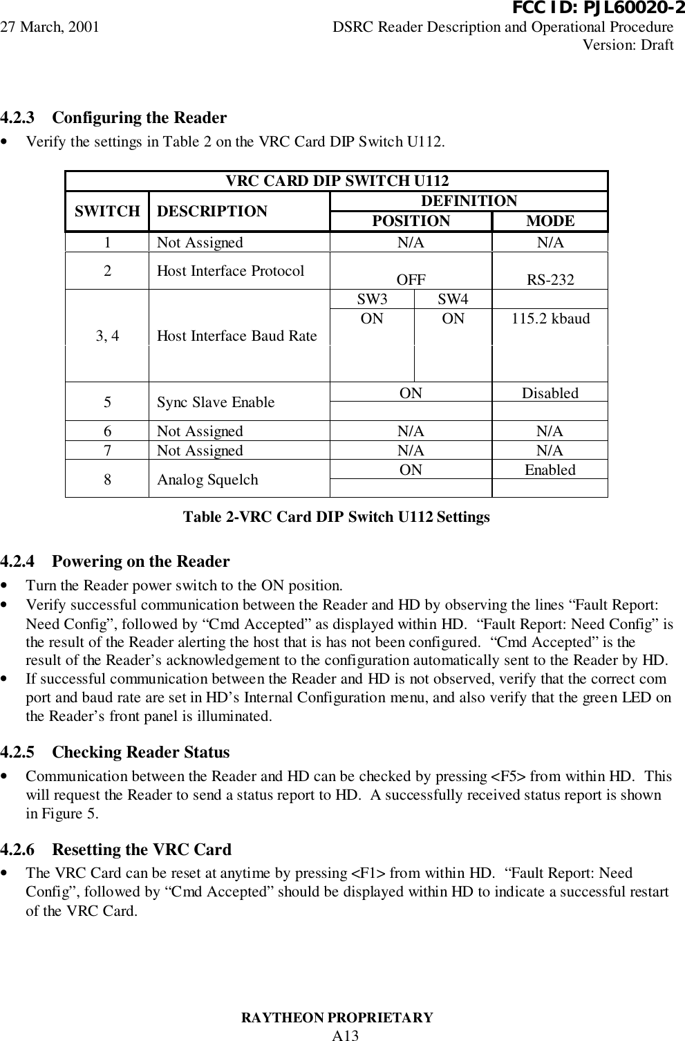
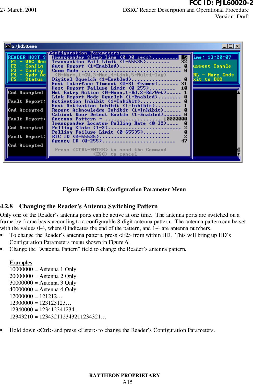
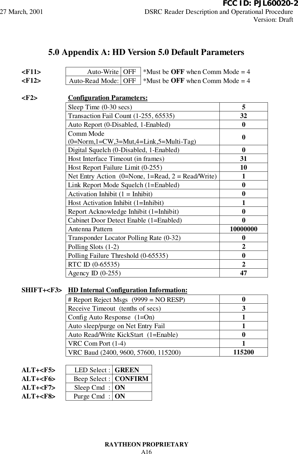
User Manual
Discussion / Help
Navigation