Raytheon IIS 60020-2 User Manual
Raytheon Company (OL) Users Manual
Users Manual
FCC ID: PJL60020-2
RAYTHEON PROPRIETARY
A1
Appendix A

FCC ID: PJL60020-2
RAYTHEON PROPRIETARY
A2
DSRC Reader Description and Operational
Procedure
Version: Draft
27 March, 2001

FCC ID: PJL60020-2
27 March, 2001 DSRC Reader Description and Operational Procedure
Version: Draft
RAYTHEON PROPRIETARY
A3
Revisions
Version Date Description
Draft 03/27/2001
FCC ID: PJL60020-2
27 March, 2001 DSRC Reader Description and Operational Procedure
Version: Draft
RAYTHEON PROPRIETARY
A4
Table of Contents
1.0 Introduction ................................................................................................................................6
1.1 Scope................................................................................................................................... 6
1.2 Purpose................................................................................................................................ 6
1.3 Definitions, Abbreviations, & Acronyms................................................................................ 6
2.0 Reader Description...................................................................................................................... 7
3.0 Reader Controls and Indicators..................................................................................................... 8
3.1 Reader Power Indicator......................................................................................................... 8
3.2 Reader Power Switch............................................................................................................ 8
3.3 Vehicle-to-Roadside Communications (VRC) Card DIP Switch U112 Configuration................ 8
3.4 VRC Card Reset Indicator.....................................................................................................8
3.5 Reset Switch......................................................................................................................... 8
3.6 Squelch Adjustment Potentiometer R13 ................................................................................. 8
3.7 VRC Card Drive Adjustment Potentiometer R41 .................................................................... 9
3.8 Reader Transmit Output Power Adjustment............................................................................ 9
4.0 Reader Operation Using HD Version 5.0 .................................................................................... 10
4.1 Required Equipment ...........................................................................................................10
4.1.1 Host Driver (HD) Version 5.0 ........................................................................................ 10
4.1.2 PC (Host Computer) (486 or better) ................................................................................ 10
4.1.3 Serial Cable .................................................................................................................. 10
4.1.4 +12V DC Power Supply................................................................................................. 10
4.2 Reader Operation Procedure Using HD Version 5.0.............................................................. 11
4.2.1 Connecting the System................................................................................................... 11
4.2.2 Configuring HD Version 5.0 .......................................................................................... 11
4.2.3 Configuring the Reader.................................................................................................. 13
4.2.4 Powering on the Reader ................................................................................................. 13
4.2.5 Checking Reader Status ................................................................................................. 13
4.2.6 Resetting the VRC Card................................................................................................. 13
4.2.7 Changing the Reader’s Communication Mode................................................................. 14
4.2.8 Changing the Reader’s Antenna Switching Pattern........................................................... 15
5.0 Appendix A: HD Version 5.0 Default Parameters.......................................................................... 1
FCC ID: PJL60020-2
27 March, 2001 DSRC Reader Description and Operational Procedure
Version: Draft
RAYTHEON PROPRIETARY
A5
Index of Figures
Figure 1-Class A/B Reader Functional Block Diagram......................................................................... 7
Figure 2-Reader Operational Setup Using HD Version 5.0.................................................................. 11
Figure 3-HD Version 5.0 Startup Screen............................................................................................ 12
Figure 4-HD 5.0: Internal Configuration Menu .................................................................................. 12
Figure 5-Successful Reader Status Report Received by HD 5.0........................................................... 14
Figure 6-HD 5.0: Configuration Parameter Menu............................................................................... 15
Index of Tables
Table 1-VRC Card DIP Switch U112 Configuration............................................................................. 8
Table 2-VRC Card DIP Switch U112 Settings ................................................................................... 13
FCC ID: PJL60020-2
27 March, 2001 DSRC Reader Description and Operational Procedure
Version: Draft
RAYTHEON PROPRIETARY
A6
1.0 Introduction
1.1 Scope
This document applies to the DSRC Reader, hereafter called the Reader, part of the Dedicated Short
Range Communications (DSRC) for use in the Integrated Roadside Unit, an element of the Electronic
Tolling System.
1.2 Purpose
This document describes the Reader, and provides information on operating the Reader using Host Driver
(HD) Version 5.0 as the host.
1.3 Definitions, Abbreviations, & Acronyms
DSRC Dedicated Short Range Communications
HD Host Driver
PC Personal Computer
REM Range Extension Module
RF Radio Frequency
VRC Vehicle to Roadside Communications
FCC ID: PJL60020-2
27 March, 2001 DSRC Reader Description and Operational Procedure
Version: Draft
RAYTHEON PROPRIETARY
A7
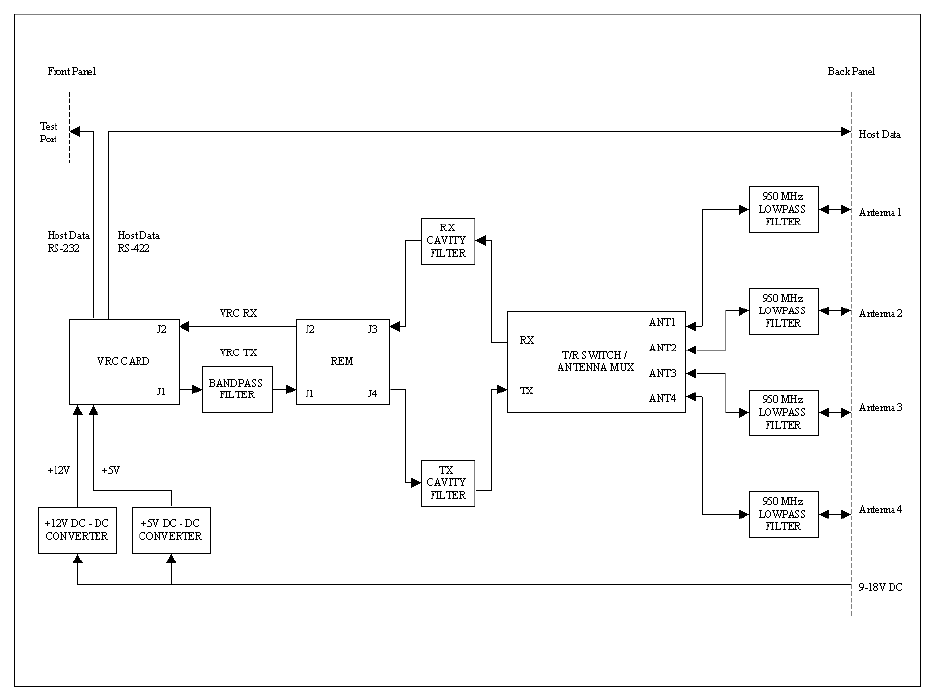
2.0 Reader Description
The Reader is an automatic vehicle identification systems that transmits and receives radio frequency
(RF) data to/from transponder-equipped vehicles or assemblies. The Reader works in conjunction with a
host computer system to identify a passing transponder, verify its operating credentials (if applicable),
communicate to the driver whether the vehicle is cleared or not (if applicable), and transmit the
transponder’s data package to the next appropriate station (dependent of the type of system connected to
the Reader). The Reader’s functional block diagram, shown in Figure 1, illustrates the interconnections
between the assemblies in the Reader’s sealed chassis.
Figure 1-Class A/B Reader Functional Block Diagram

FCC ID: PJL60020-2
27 March, 2001 DSRC Reader Description and Operational Procedure
Version: Draft
RAYTHEON PROPRIETARY
A8
3.0 Reader Controls and Indicators
3.1 Reader Power Indicator
A green LED on the front panel of the Reader is lit when the Reader is powered ON.
3.2 Reader Power Switch
A rocker switch on the front panel of the Reader is used to power the Reader ON and OFF.
3.3 Vehicle-to-Roadside Communications (VRC) Card DIP Switch U112 Configuration
The configuration for DIP Switch U112 on the VRC Card is illustrated in Table 1.
VRC CARD DIP SWITCH U112
DEFINITION
SWITCH DESCRIPTION POSITION MODE
1 Not Assigned N/A N/A
ON RS-422
2 Host Interface Protocol OFF RS-232
SW3 SW4
ON ON 115.2 kbaud
ON OFF 57.6 kbaud
OFF ON 38.4 kbaud
3, 4 Host Interface Baud Rate
OFF OFF 9.6 kbaud
ON Disabled
5 Sync Slave Enable OFF Enabled
6 Not Assigned N/A N/A
7 Not Assigned N/A N/A
ON Enabled
8 Analog Squelch OFF Disabled
Table 1-VRC Card DIP Switch U112 Configuration
3.4 VRC Card Reset Indicator
The red LED (DS1) on the VRC Card lights for approximately 1-2 seconds, then remains OFF when the
reset switch (S100) on the VRC Card is pressed, or when the Reader is powered ON.
3.5 Reset Switch
The microprocessor (U100) on the VRC Card is reset when the reset switch on the VRC Card (S100) is
pressed.
3.6 Squelch Adjustment Potentiometer R13
Potentiometer R13 (closest to the DB-37 connector) on the VRC Card is used to adjust the sensitivity and
communication range of the Reader. When the potentiometer adjustment screw is turned clockwise, the
Reader is more sensitive to transponders and the communication range increases. When the
potentiometer adjustment screw is turned counterclockwise, the Reader is less sensitive to transponders
and the communication range decreases. This potentiometer adjustment should only be performed by
qualified, trained technicians.
FCC ID: PJL60020-2
27 March, 2001 DSRC Reader Description and Operational Procedure
Version: Draft
RAYTHEON PROPRIETARY
A9
3.7 VRC Card Drive Adjustment Potentiometer R41
Potentiometer R41 (furthest from the DB-37 connector) on the VRC Card is to be used only by a
qualified technician to adjust the transmit power output drive level of the VRC Card. Clockwise rotation
of the potentiometer adjustment screw increases the transmit power drive; counterclockwise rotation
decreases the transmit power drive.
NOTE: The Reader output power should not be adjusted using this method. See section 3.8 for correct
output power adjustment.
3.8 Reader Transmit Output Power Adjustment
Potentiometer R5 on the REM is to be used only by a qualified technician to adjust the transmit output
power output level of the Reader. Clockwise rotation of the potentiometer adjustment screw increases the
transmit power level output; counterclockwise rotation decreases the transmit power level output.
FCC ID: PJL60020-2
27 March, 2001 DSRC Reader Description and Operational Procedure
Version: Draft
RAYTHEON PROPRIETARY
A10
4.0 Reader Operation Using HD Version 5.0
4.1 Required Equipment
4.1.1 Host Driver (HD) Version 5.0
Test program designed to simulate a Reader host system.
4.1.2 PC (Host Computer) (486 or better)
Used to run HD Version 5.0. Interface to the Reader is to be either RS-232, or RS-422, which would
require an RS-422 to RS-232 adapter between the Host Computer and the Reader. When the interface is
selected to be RS-232, the PC is connected to the Test Port (RS-232) port. When the interface is selected
to be RS-422, the PC is connected to an RS-232-to-RS-422 converter, and the converter is connected to
the Host Data (RS-422) port.
4.1.3 Serial Cable
DB-9 Female to DB-9 Male RS-232 serial adapter cable used to connect the Reader and the PC.
4.1.4 +12V DC Power Supply
Used to provide power to the Reader. A minimum rating of 3.5A is required.
FCC ID: PJL60020-2
27 March, 2001 DSRC Reader Description and Operational Procedure
Version: Draft
RAYTHEON PROPRIETARY
A11
4.2 Reader Operation Procedure Using HD Version 5.0
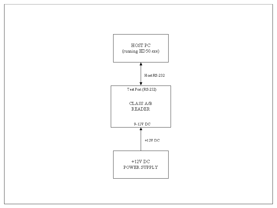
4.2.1 Connecting the System
• Turn the Reader Power switch to the OFF position.
• Connect the system per Figure 2.
Figure 2-Reader Operational Setup Using HD Version 5.0
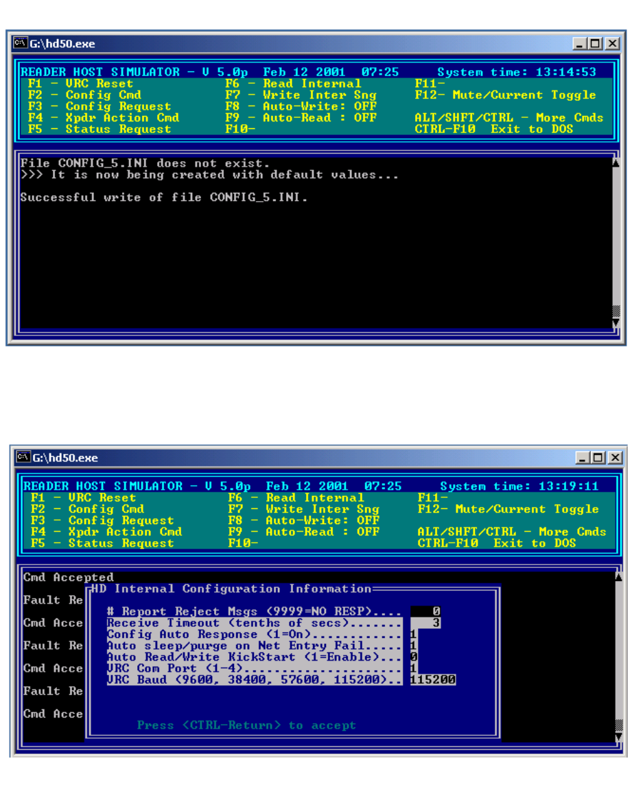
4.2.2 Configuring HD Version 5.0
• Run HD 5.0 (HD50.exe) on the PC. Figure 3 is a screenshot of the HD Version 5.0 application upon
startup.
• Within HD 5.0, hold down <Shift>, and press <F3>. This will bring up HD’s Internal Configuration
menu shown in Figure 4.
• In the field “VRC Com Port (1-4)”, enter the number of the serial port that HD will be using to
communicate with the Reader.
• Verify that the field “VRC Baud (9600, 38400, 57600, 115200)” is set to 115200.
• Hold down <Ctrl>, and press <Enter> to change the Internal Configuration.
FCC ID: PJL60020-2
27 March, 2001 DSRC Reader Description and Operational Procedure
Version: Draft
RAYTHEON PROPRIETARY
A12
Figure 3-HD Version 5.0 Startup Screen
Figure 4-HD 5.0: Internal Configuration Menu

FCC ID: PJL60020-2
27 March, 2001 DSRC Reader Description and Operational Procedure
Version: Draft
RAYTHEON PROPRIETARY
A13
4.2.3 Configuring the Reader
• Verify the settings in Table 2 on the VRC Card DIP Switch U112.
VRC CARD DIP SWITCH U112
DEFINITION
SWITCH DESCRIPTION POSITION MODE
1 Not Assigned N/A N/A
2 Host Interface Protocol OFF RS-232
SW3 SW4
ON ON 115.2 kbaud
3, 4 Host Interface Baud Rate
ON Disabled
5 Sync Slave Enable
6 Not Assigned N/A N/A
7 Not Assigned N/A N/A
ON Enabled
8 Analog Squelch
Table 2-VRC Card DIP Switch U112 Settings
4.2.4 Powering on the Reader
• Turn the Reader power switch to the ON position.
• Verify successful communication between the Reader and HD by observing the lines “Fault Report:
Need Config”, followed by “Cmd Accepted” as displayed within HD. “Fault Report: Need Config” is
the result of the Reader alerting the host that is has not been configured. “Cmd Accepted” is the
result of the Reader’s acknowledgement to the configuration automatically sent to the Reader by HD.
• If successful communication between the Reader and HD is not observed, verify that the correct com
port and baud rate are set in HD’s Internal Configuration menu, and also verify that the green LED on
the Reader’s front panel is illuminated.
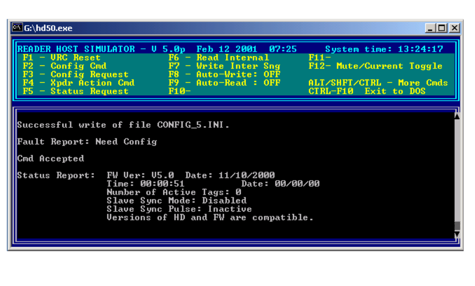
4.2.5 Checking Reader Status
• Communication between the Reader and HD can be checked by pressing <F5> from within HD. This
will request the Reader to send a status report to HD. A successfully received status report is shown
in Figure 5.
4.2.6 Resetting the VRC Card
• The VRC Card can be reset at anytime by pressing <F1> from within HD. “Fault Report: Need
Config”, followed by “Cmd Accepted” should be displayed within HD to indicate a successful restart
of the VRC Card.
FCC ID: PJL60020-2
27 March, 2001 DSRC Reader Description and Operational Procedure
Version: Draft
RAYTHEON PROPRIETARY
A14
Figure 5-Successful Reader Status Report Received by HD 5.0
4.2.7 Changing the Reader’s Communication Mode
Normal and Mute mode are two of the Reader’s communication modes that are useful for this
implementation of the Reader. Normal mode is the Reader’s normal modulated mode of operation. Mute
mode places the Reader’s transmitter is a disabled state. The Reader starts up in Mute mode and will
remain in this mode until it is successfully configured. When the Reader is powered ON and is informing
the host that it is not configured, HD will automatically (depending on the state of the “Config Auto
Response” in HD’s Internal Configuration menu) configure the Reader. The default parameters for HD
5.0 are listed in Appendix A.
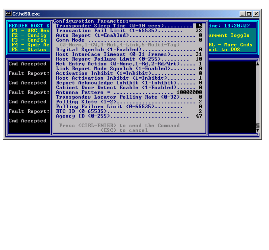
• To change the Reader’s communication mode, press <F2> from within HD. This will bring up HD’s
Configuration Parameters menu shown in Figure 6.
• Change the “Comm Mode” field to change the Reader’s communication mode.
0 = Normal Mode
3 = Mute Mode
• Hold down <Ctrl> and press <Enter> to change the Reader’s Configuration Parameters.
FCC ID: PJL60020-2
27 March, 2001 DSRC Reader Description and Operational Procedure
Version: Draft
RAYTHEON PROPRIETARY
A15
Figure 6-HD 5.0: Configuration Parameter Menu
4.2.8 Changing the Reader’s Antenna Switching Pattern
Only one of the Reader’s antenna ports can be active at one time. The antenna ports are switched on a
frame-by-frame basis according to a configurable 8-digit antenna pattern. The antenna pattern can be set
with the values 0-4, where 0 indicates the end of the pattern, and 1-4 are antenna numbers.
• To change the Reader’s antenna pattern, press <F2> from within HD. This will bring up HD’s
Configuration Parameters menu shown in Figure 6.
• Change the “Antenna Pattern” field to change the Reader’s antenna pattern.
Examples
10000000 = Antenna 1 Only
20000000 = Antenna 2 Only
30000000 = Antenna 3 Only
40000000 = Antenna 4 Only
12000000 = 121212…
12300000 = 123123123…
12340000 = 123412341234…
12343210 = 123432112343211234321…
• Hold down <Ctrl> and press <Enter> to change the Reader’s Configuration Parameters.
FCC ID: PJL60020-2
27 March, 2001 DSRC Reader Description and Operational Procedure
Version: Draft
RAYTHEON PROPRIETARY
A16
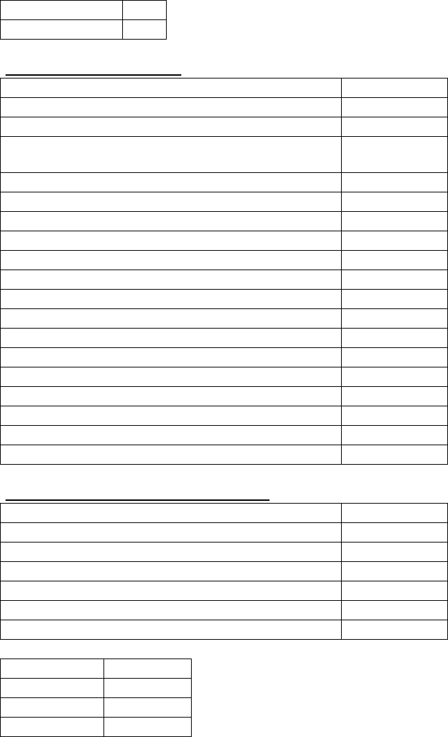
5.0 Appendix A: HD Version 5.0 Default Parameters
<F11> Auto-Write OFF *Must be OFF when Comm Mode = 4
<F12> Auto-Read Mode: OFF *Must be OFF when Comm Mode = 4
<F2> Configuration Parameters:
Sleep Time (0-30 secs) 5
Transaction Fail Count (1-255, 65535) 32
Auto Report (0-Disabled, 1-Enabled) 0
Comm Mode
(0=Norm,1=CW,3=Mut,4=Link,5=Multi-Tag) 0
Digital Squelch (0-Disabled, 1-Enabled) 0
Host Interface Timeout (in frames) 31
Host Report Failure Limit (0-255) 10
Net Entry Action (0=None, 1=Read, 2 = Read/Write) 1
Link Report Mode Squelch (1=Enabled) 0
Activation Inhibit (1 = Inhibit) 0
Host Activation Inhibit (1=Inhibit) 1
Report Acknowledge Inhibit (1=Inhibit) 0
Cabinet Door Detect Enable (1=Enabled) 0
Antenna Pattern 10000000
Transponder Locator Polling Rate (0-32) 0
Polling Slots (1-2) 2
Polling Failure Threshold (0-65535) 0
RTC ID (0-65535) 2
Agency ID (0-255) 47
SHIFT+<F3> HD Internal Configuration Information:
# Report Reject Msgs (9999 = NO RESP) 0
Receive Timeout (tenths of secs) 3
Config Auto Response (1=On) 1
Auto sleep/purge on Net Entry Fail 1
Auto Read/Write KickStart (1=Enable) 0
VRC Com Port (1-4) 1
VRC Baud (2400, 9600, 57600, 115200) 115200
ALT+<F5> LED Select : GREEN
ALT+<F6> Beep Select : CONFIRM
ALT+<F7> Sleep Cmd : ON
ALT+<F8> Purge Cmd : ON