Realtek Semiconductor RTU7010-DWAV31 DWA User Manual 1
Realtek Semiconductor Corp. DWA 1
User manual rev

Realtek DWA User Guide.doc
Realtek DWA User’s Guide
Revision A
Author : Robert Teng
Date : 06/03/2007
Realtek Corp.
1
All Rights Reserved by Realtek Corp.

Realtek DWA User Guide.doc
Table of Contents
1. Introduction .............................................................................. 3
2. System Description................................................................... 3
2.1. UWB PHY....................................................................... 4
2.2. NEC MAC....................................................................... 4
2.3. EEPROM......................................................................... 4
3. Hardware Interfaces.................................................................. 5
3.1. USB Interface.......................................................................................... 5
4. Document History……………………………………………...5
5. Radiation Exposure Statement…………………………………5
6. Interference Statement …………………………………………6
7. Coordination Requirements………………………………….6
2
All Rights Reserved by Realtek Corp.
Realtek DWA User Guide.doc
1. Introduction
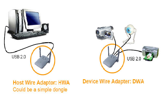
This document describes the operations, interfaces, schematic and layout of
Rev. 2.1 of the NEC DWA Demo Board. The DWA is the hub function device
to connect wired USB device with wireless USB host controller. If the
upstream port is connected to host PC with USB cable, DWA worked as wired
USB Hub device. If DWA upstream port isn’t connected to host PC, DWA
can worked as wireless USB Hub device.
2. System Description
The DWA supports the following functions:
Compliant with USB2.0(max. data rate=480 Mbps)
Supports for 4 downstream facing ports.
Support full speed and low speed transaction on downstream facing.
Supports switches to select associated hosts and LEDs to indicate
connecting host.
Support 53.3M, 80M, 106.7M, 160M, 200M, 320M, 400M, 480Mbps.
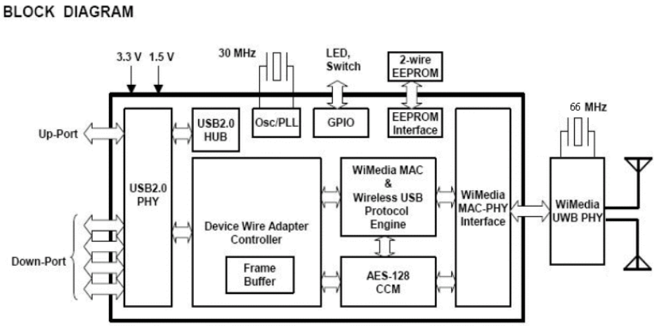
The DWA system mainly consists of two main chips – (i) UWB
PHY(RTU7010), (ii) NEC MAC(UPD720180). Up to two antennas can be
supported by the UWB PHY for performance improvement. A serial
EEPROM(256K) is required to store proper data/commands for the PHY chip
and MAC chip. To make the system work properly, the EEPROM should be
loaded with proper content by using the EEPROM utility provided by NEC.
3
All Rights Reserved by Realtek Corp.
Realtek DWA User Guide.doc
The RF performance can also be tested using the test utility provided by NEC.
Two basic clock frequencies are used in the system – 30MHz for MAC and
66MHz for PHY. Some more details of the components are shown in the
following sections. The system block diagram is shown below.
Figure 1 System Block Diagram
2.1. UWB PHY
This chip integrates the RF and baseband functions of a UWB PHY defined
by the standard. This version of PHY chip is packaged in 48-pin QFN form
factor. The analog/RF section requires 1.8V and 3.3V to operate. The digital
core operates with 1.5V and the I/O voltage can support a range of 1.8V~3.3V.
2.2. NEC MAC
This MAC chip is from NEC which has a standard MPI interface to
communicate with a standard UWB PHY, as well as a high speed USB
interface(the upstream port) to connect directly to a PC. This chip requires
voltages of 1.5V and 3.3V.
2.3. EEPROM
This chip is a serial EEPROM from Atmel with a capacity of 256Kb. It is used
by the MAC to store the initialization data and command sequence required
by the MAC and PHY on start up. This chip requires 3.3V only.
4
All Rights Reserved by Realtek Corp.

Realtek DWA User Guide.doc
3. Hardware Interfaces
3.1. USB Interface
Table 1 USB series “Mini-B” connector termination assignment
Pin# Pin Name Description
1 VBUS See USB specification
2 D- See USB specification
3 D+ See USB specification
4 NC See USB specification
5 GND See USB specification
6 SHELL See USB specification
4. Document History
Date Revision Description Author
06/03/07 A Initial Release Robert Teng
5. Radiation Exposure Statement
This equipment complies with FCC radiation exposure limits set forth
for an uncontrolled environment. This equipment should be installed
and operated with minimum distance 20cm between the radiator &
your body.
This transmitter must not be co-located or operating in conjunction
with any other antenna or transmitter.
This device may only be operated indoors. Operation outdoors is in
violation of 47 U.S.C. 301 and could subject the operator to serious
legal penalties.
5
All Rights Reserved by Realtek Corp.
Realtek DWA User Guide.doc
6. Interference Statement
This equipment has been tested and found to comply with the limits
for a Class B digital device, pursuant to Part 15 of the FCC Rules.
These limits are designed to provide reasonable protection against
harmful interference in a residential installation. This equipment
generates, uses and can radiate radio frequency energy and, if not
installed and used in accordance with the instructions, may cause
harmful interference to radio communications. However, there is no
guarantee that interference will not occur in a particular installation.
If this equipment does cause harmful interference to radio or
television reception, which can be determined by turning the
equipment off and on, the user is encouraged to try to correct the
interference by one of the following measures:
- Reorient or relocate the receiving antenna.
- Increase the separation between the equipment and receiver.
- Connect the equipment into an outlet on a circuit different
from that
to which the receiver is connected.
- Consult the dealer or an experienced radio/TV technician for
help.
CAUTION: Any changes of modifications not expressly approved by
the grantee of this device could void the user’s authority to operate
the equipment.
7. Coordination Requirements
For real application, the transmitter will only be active when
communicating with the specific receiver through handshaking,
acknowledgement and other mechanisms over the wireless channel.
6
All Rights Reserved by Realtek Corp.