Redline Communications AN100UA Wireless Access Base Station User Manual 70 00058 01 01
Redline Communications Inc. Wireless Access Base Station 70 00058 01 01
UserManual.wiki
>
Redline Communications
>
AN100UA User Manual
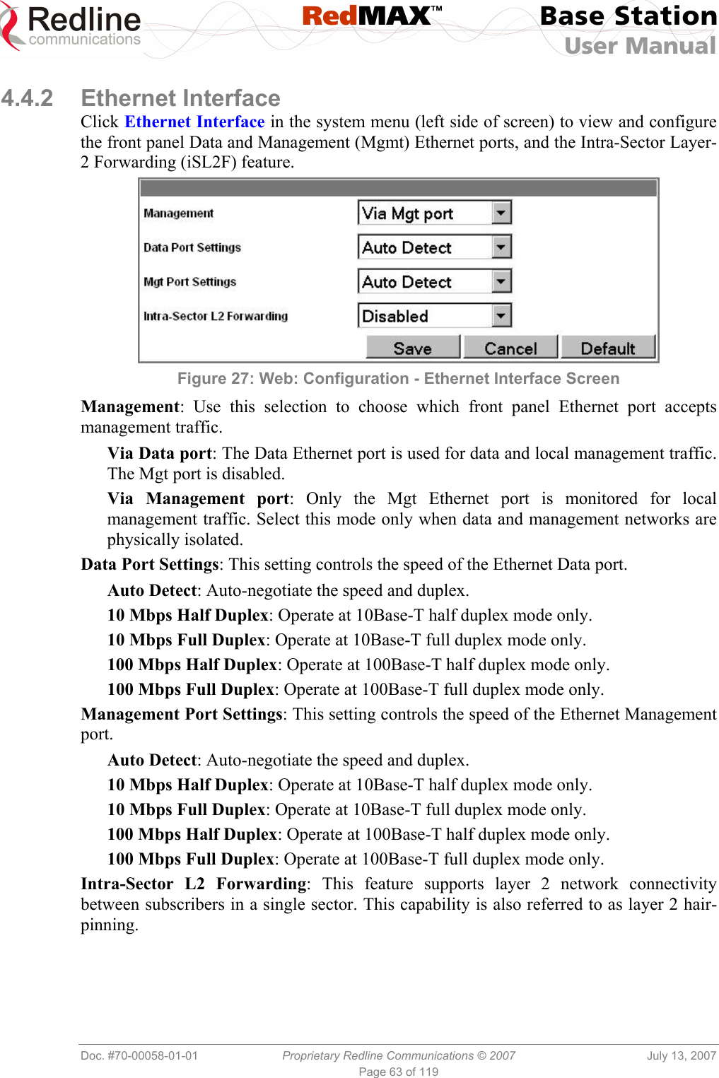
User Manual
Navigation menu
Upload a User Manual
Namespaces
Wiki Guide
HTML
PDF
Info
Views
User Manual
Discussion / Help
Navigation

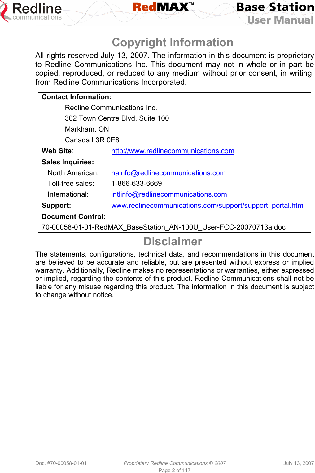
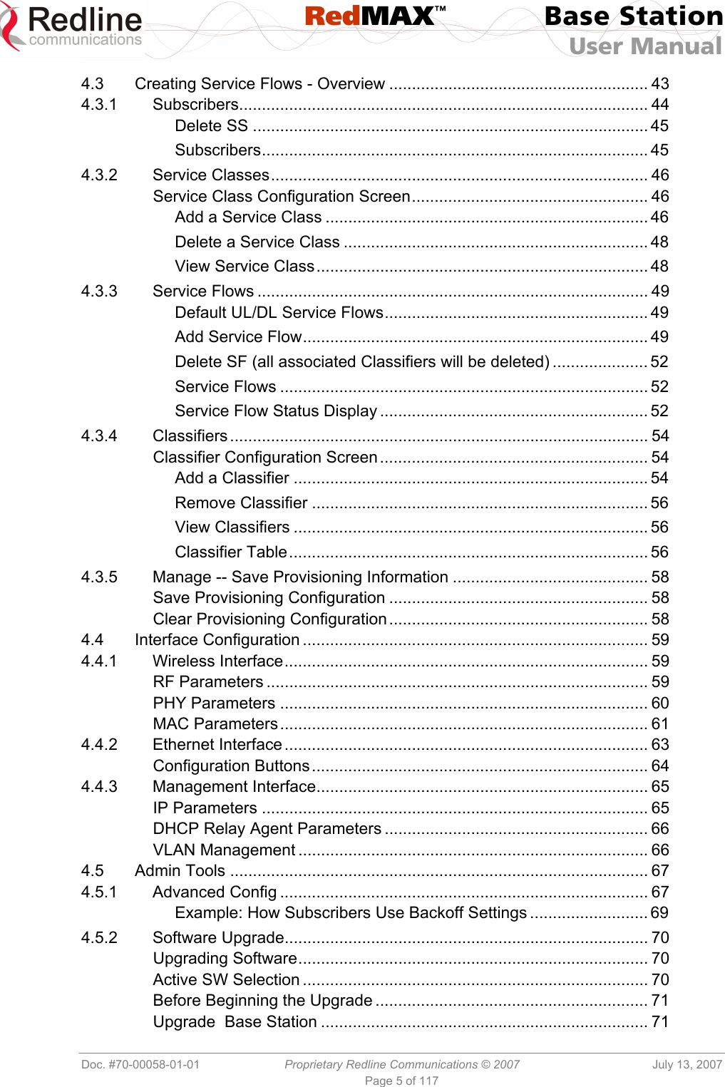
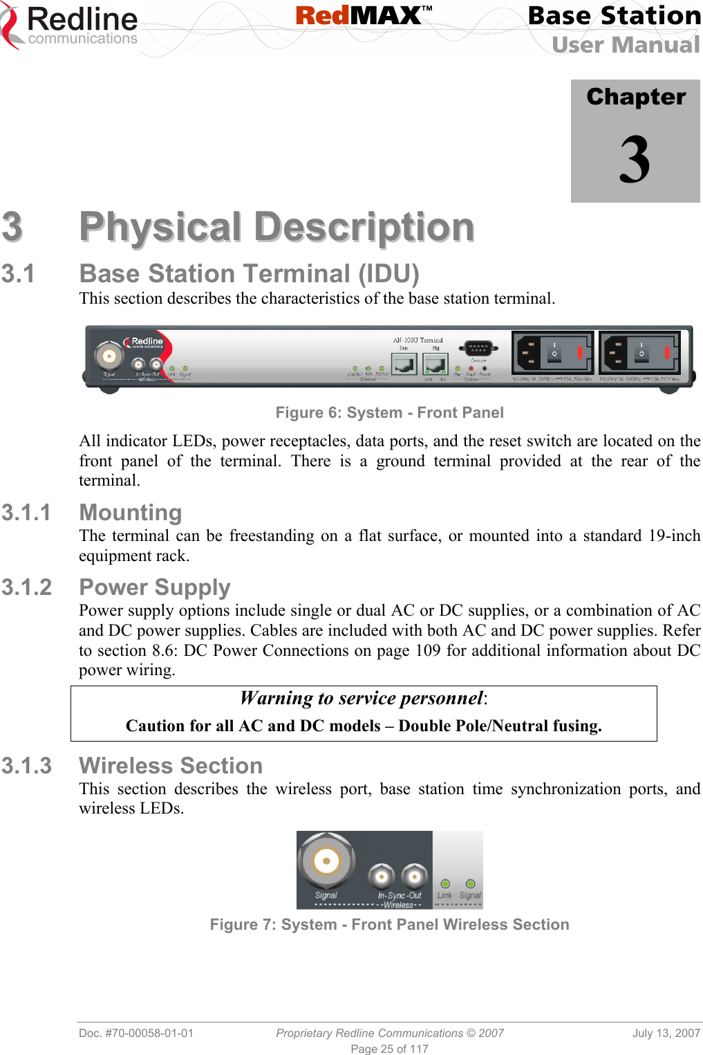
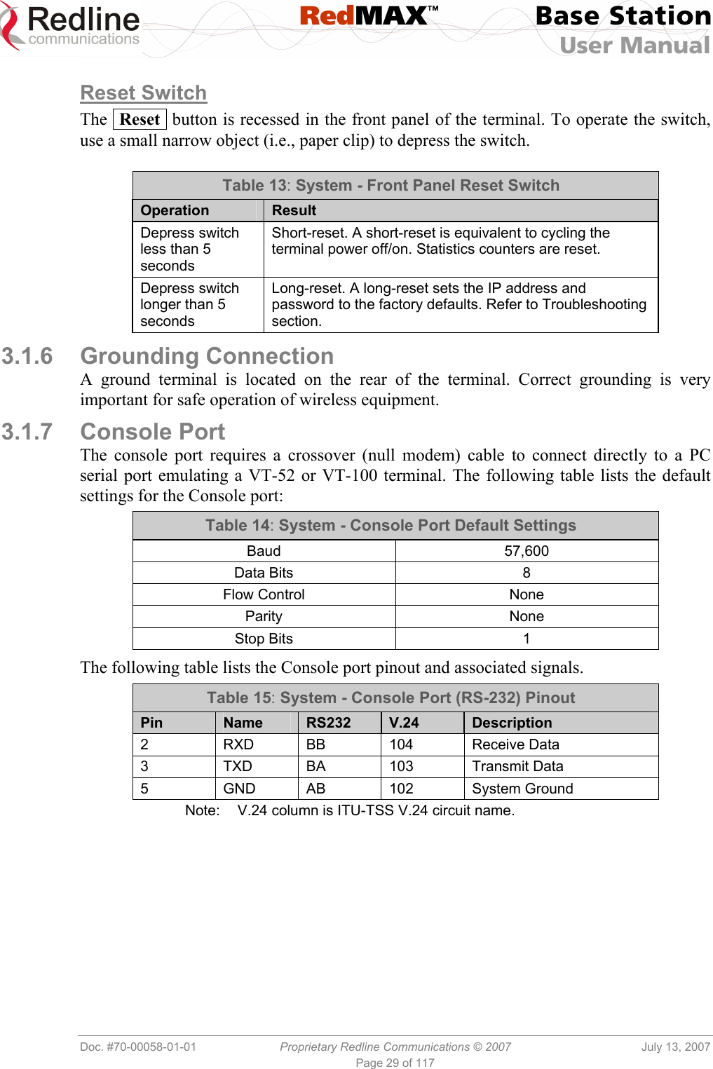
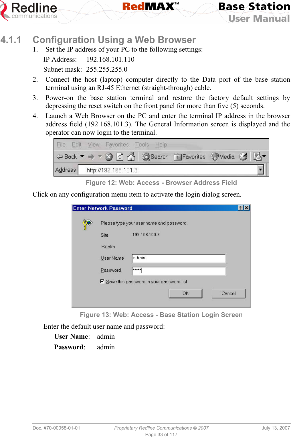
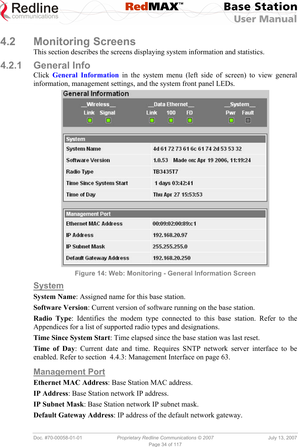
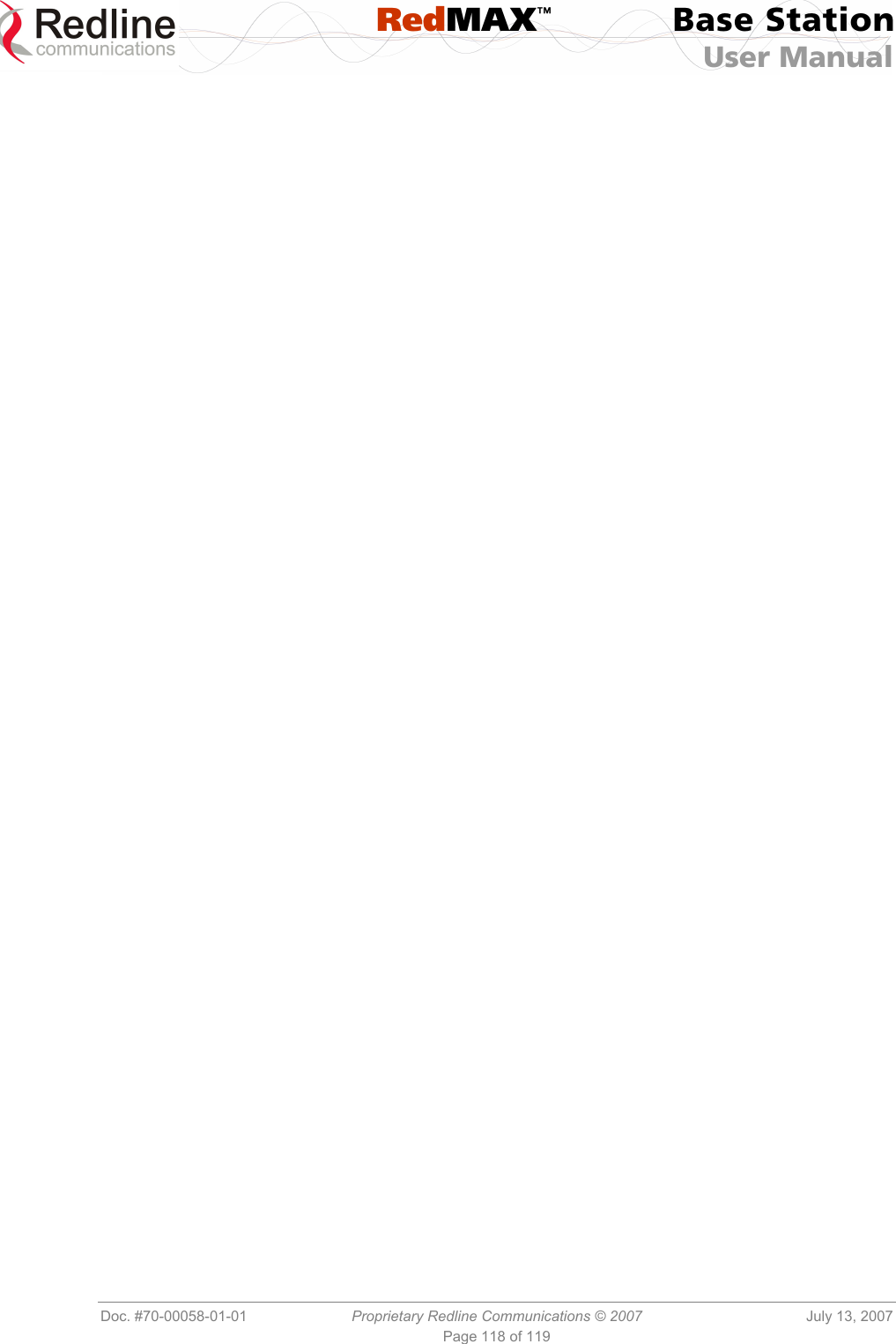
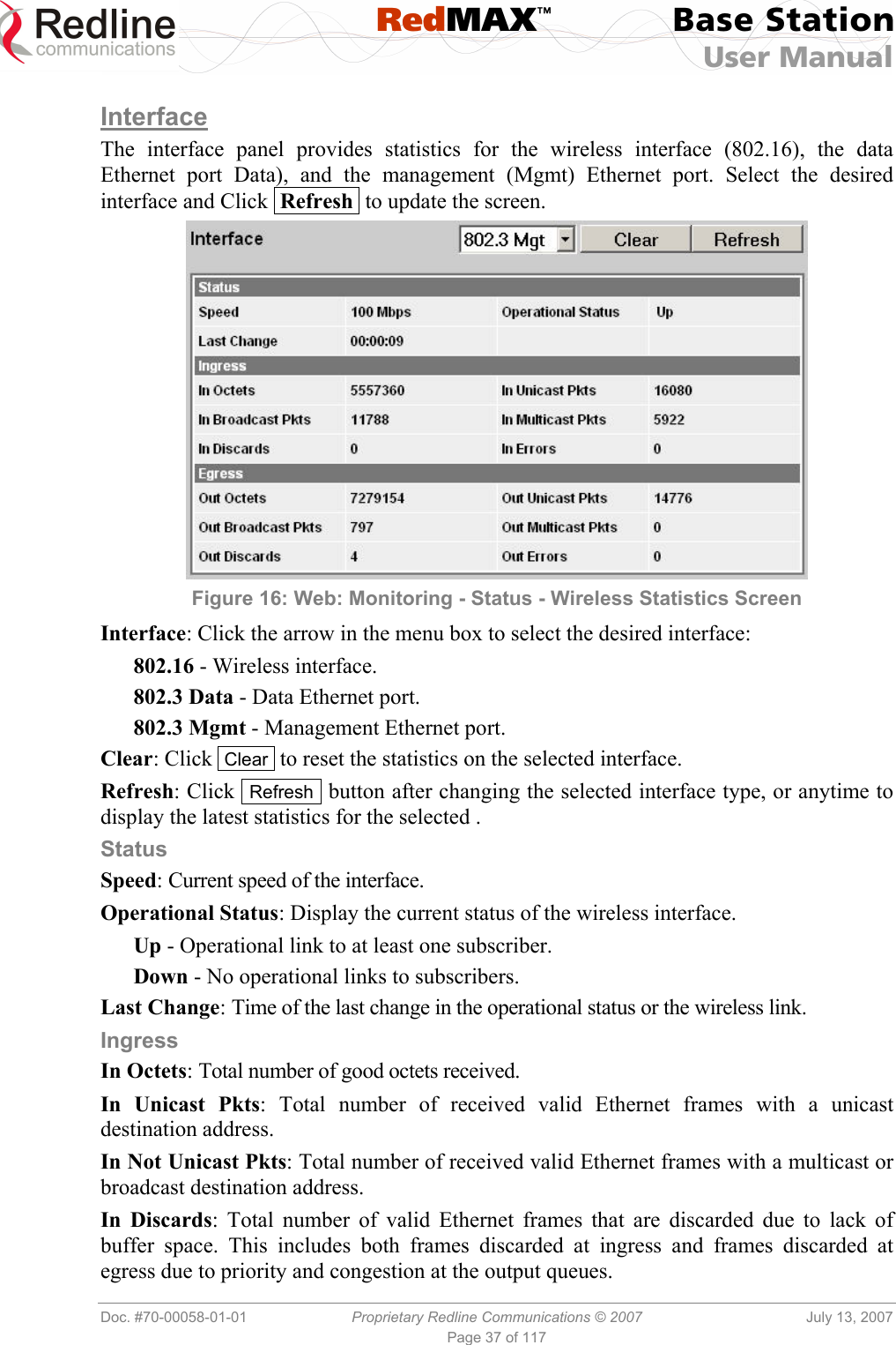
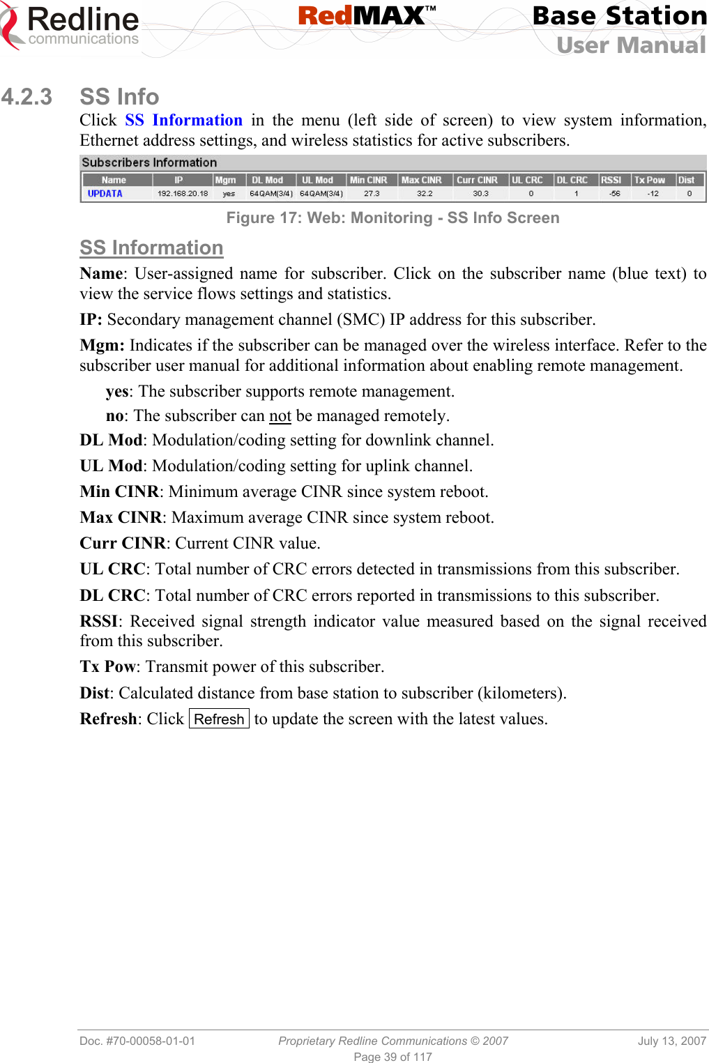
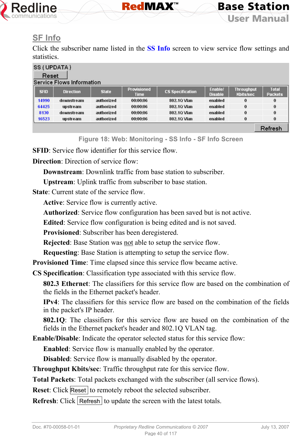
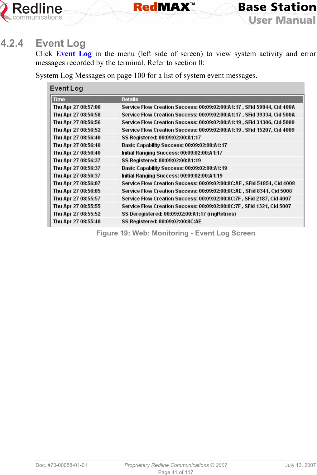
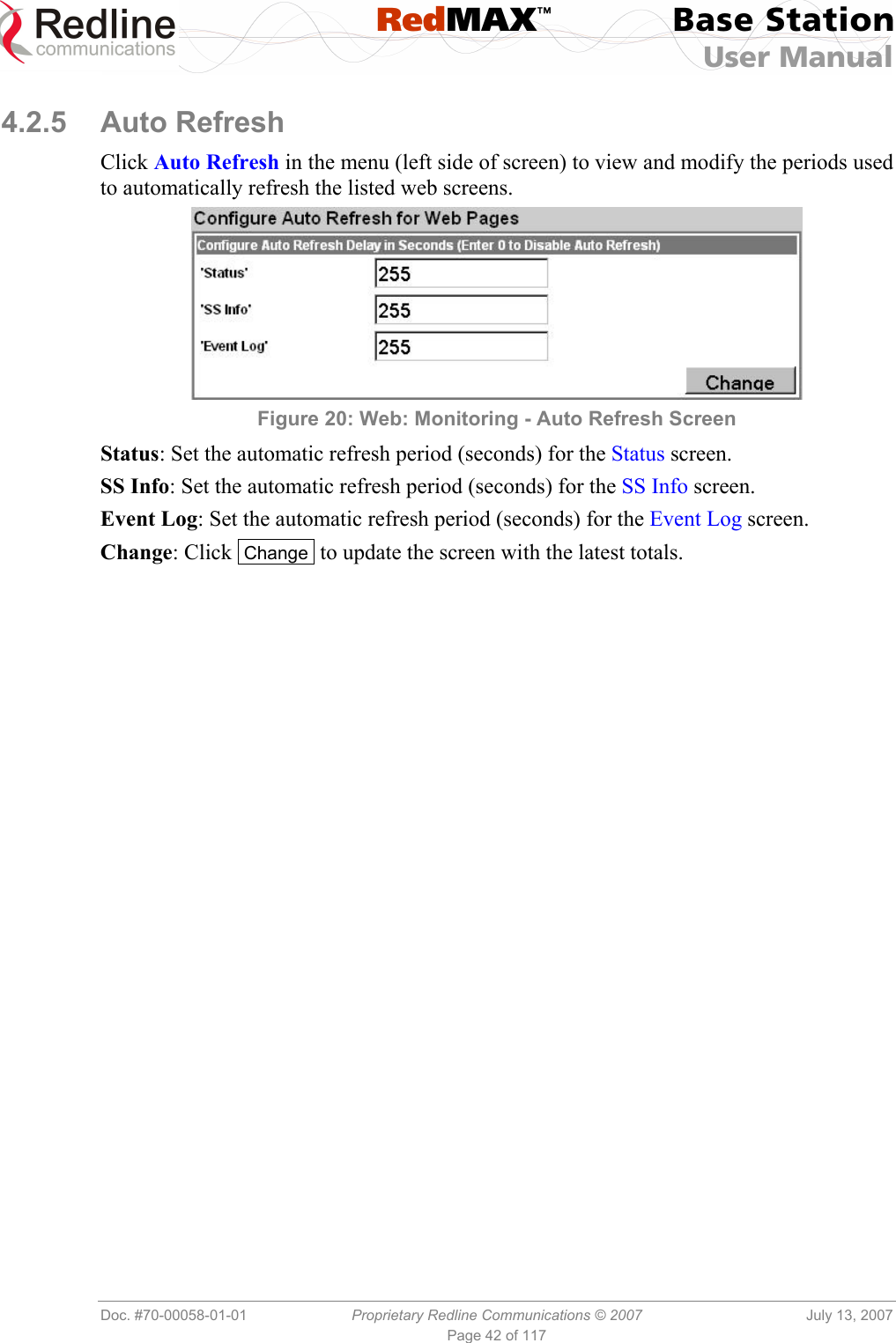
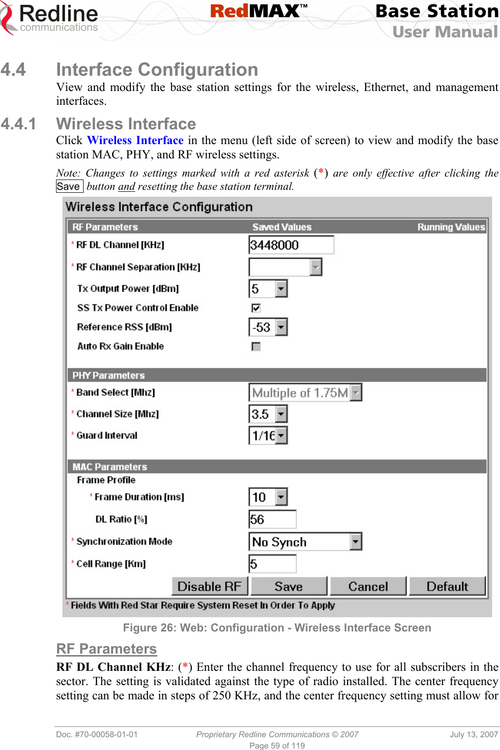
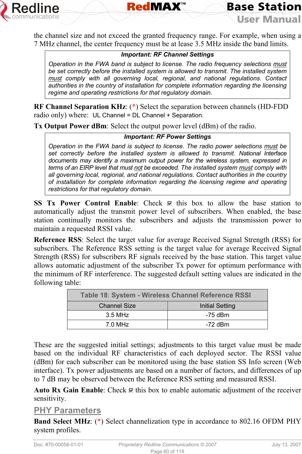
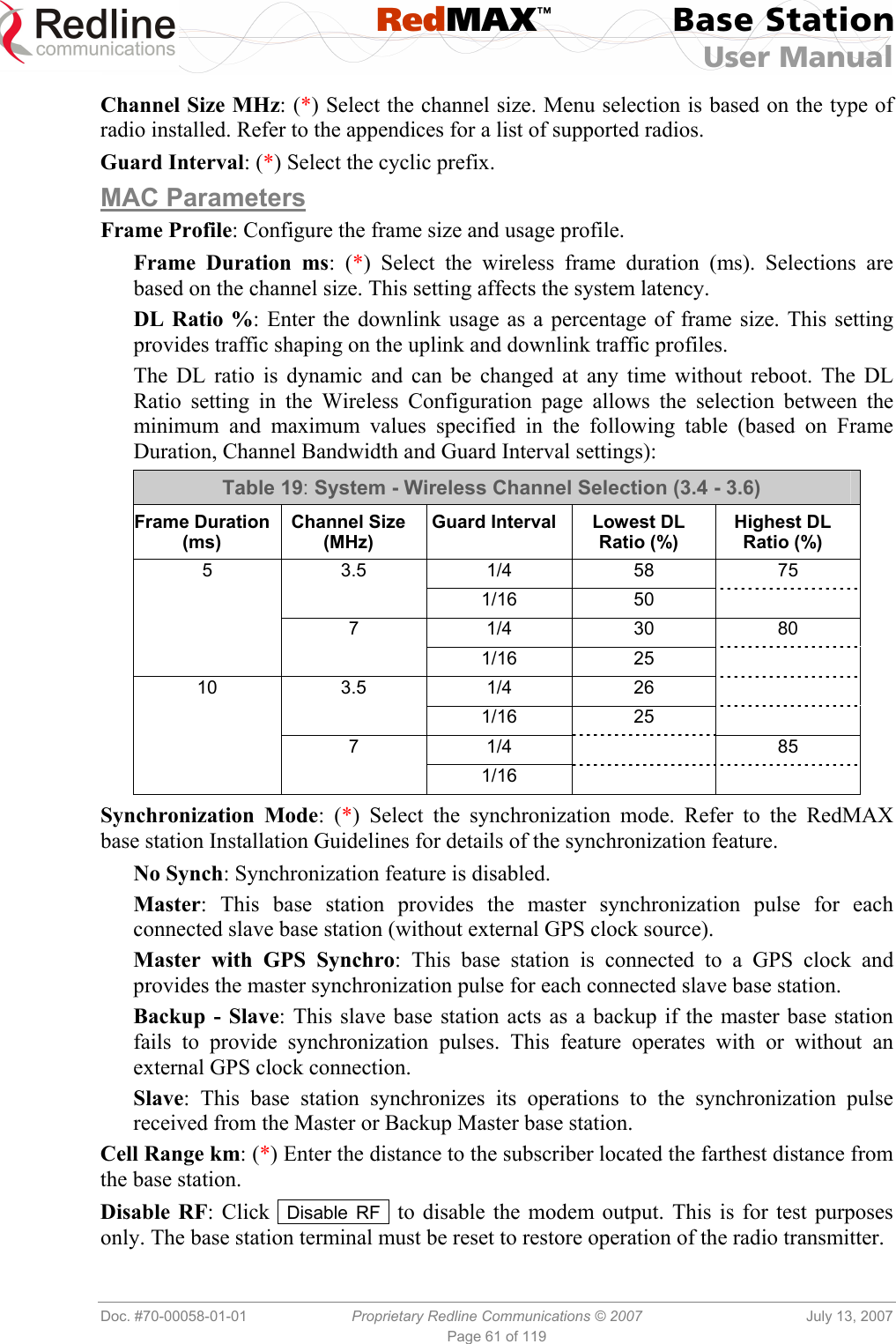
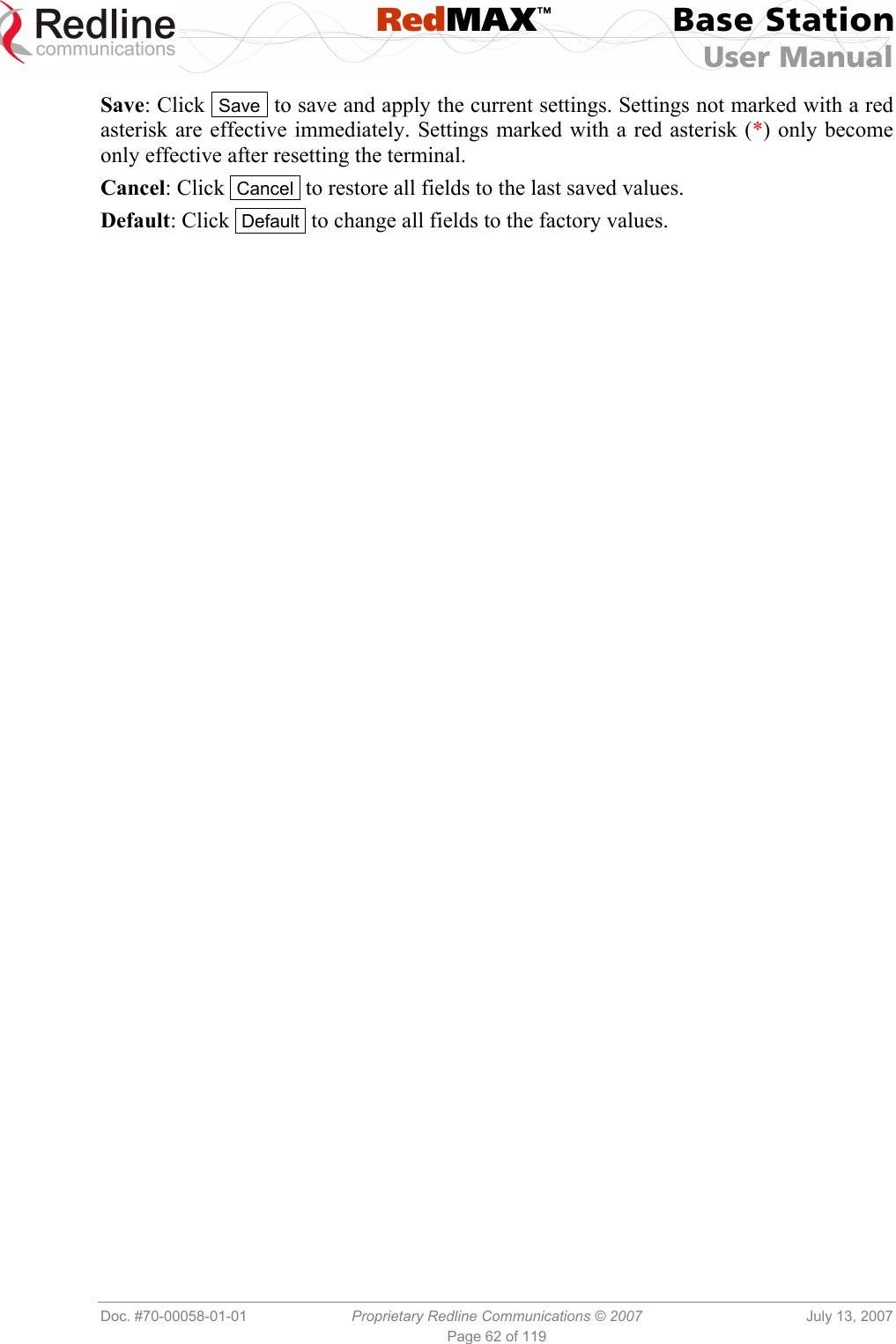
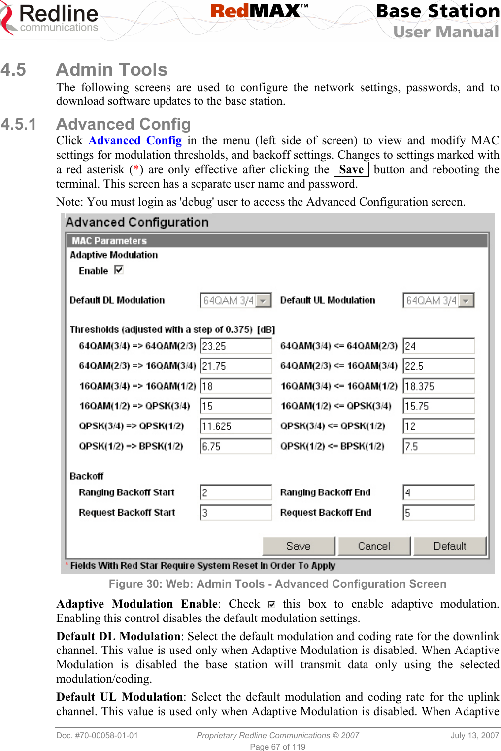
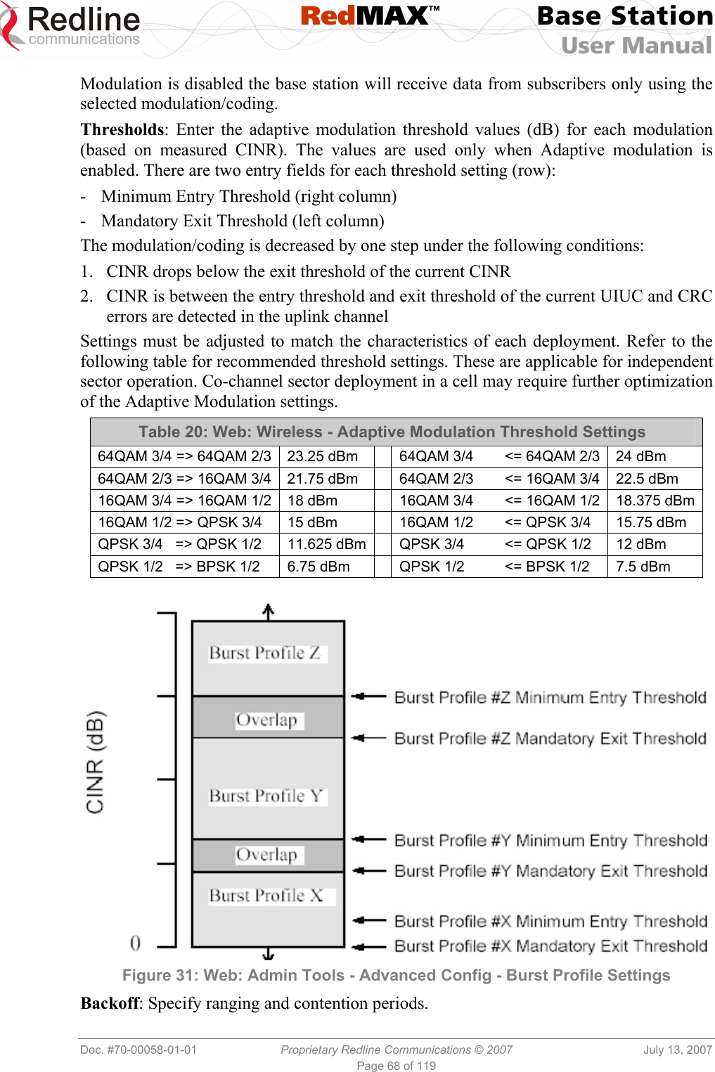
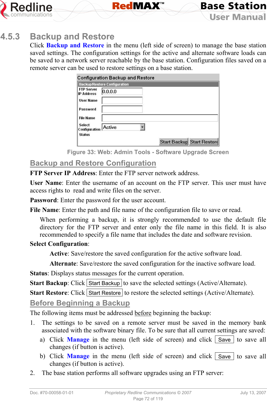
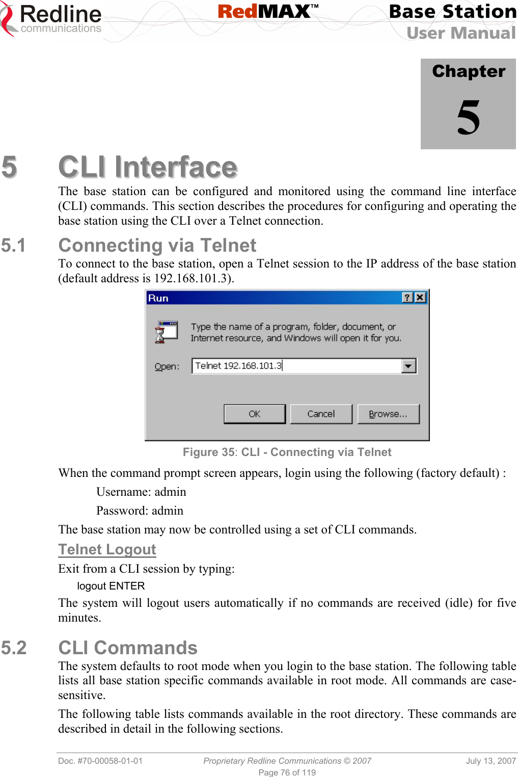
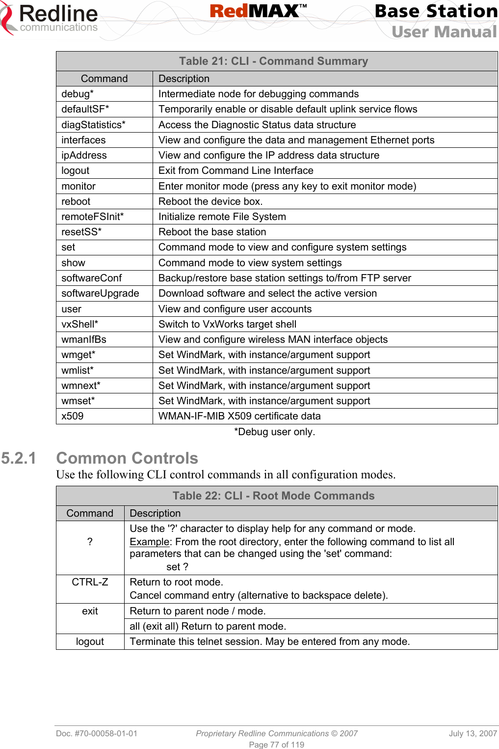
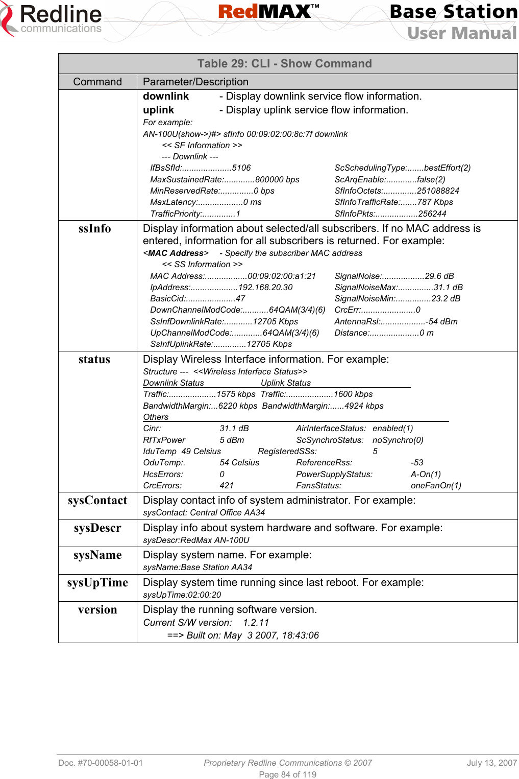
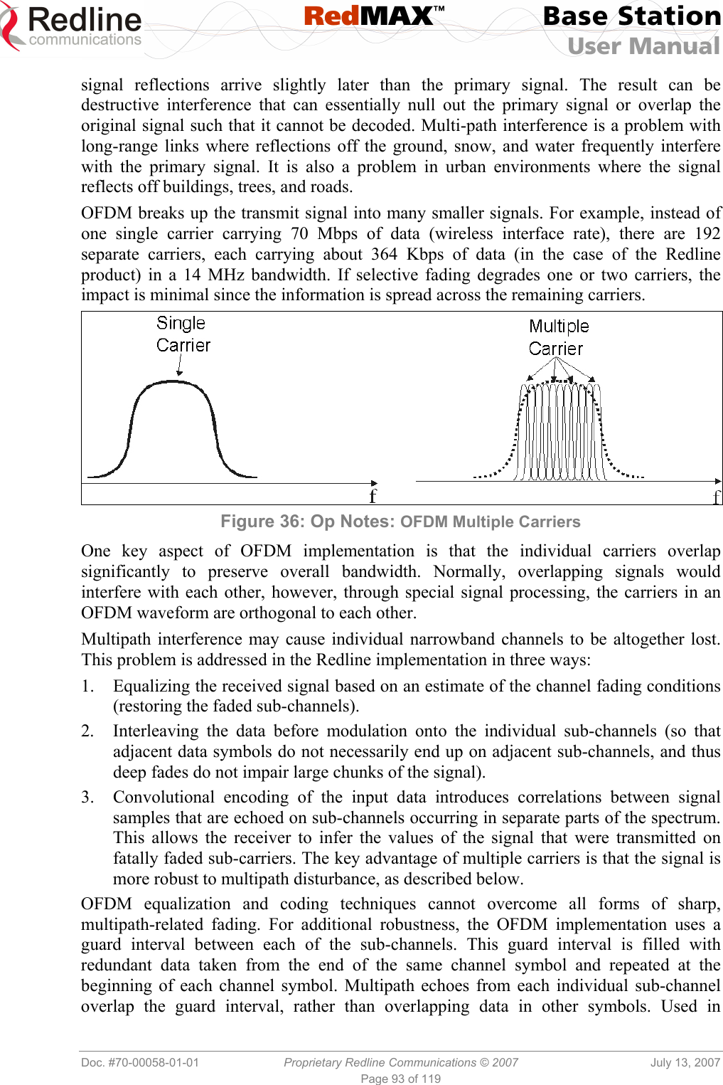
![RedMAX™ Base Station User Manual Doc. #70-00058-01-01 Proprietary Redline Communications © 2007 July 13, 2007 Page 35 of 117 4.2.2 Status Click Status in the system menu (left side of screen) to view status information about the wireless interface and Ethernet management interface. Values are updated according to the screen refresh rate. Figure 15: Web: Monitoring - Status - Wireless Status Screen Wireless Status CINR [dB]: Mean Carrier/(Interference + Noise) ratio. The CINR value is calculated and displayed for each automatic screen refresh. The CINR measured by the base station is based on the signal from the subscriber. Based on this value, the base station may request that the subscriber change modulation rate. Traffic Downlink [kbps]: Rate of traffic transmitted to subscribers. BW Margin Downlink [kbps]: Downlink bandwidth available that can be scheduled by the base station (based on the minimum traffic rate settings for all active service flows). CRC Errors: Number of CRC errors detected on packets received from subscribers. This counter is reset when an base station is rebooted. Note: The CRC Errors counter in the SS Info screen is reset when a subscriber is registered. Air Interface Status: Status of the base station modem: Enabled - Transceiver is operating normally. Disabled - Transceiver is disconnected, disabled, or defective. IDU Temperature [Celsius]: Internal temperature of the indoor terminal. Power Supply Status: Display the status of the power circuits. A-On - Terminal is equipped with AC circuits only. D-On - Terminal is equipped with DC circuits only. A-D - Terminal is equipped with AC and DC circuits. Active DL Service Flows: Number of currently active downlink service flows. DL SMC Rate [kbps]: Data rate for downlink channel.](https://usermanual.wiki/Redline-Communications/AN100UA/User-Guide-818393-Page-35.png)
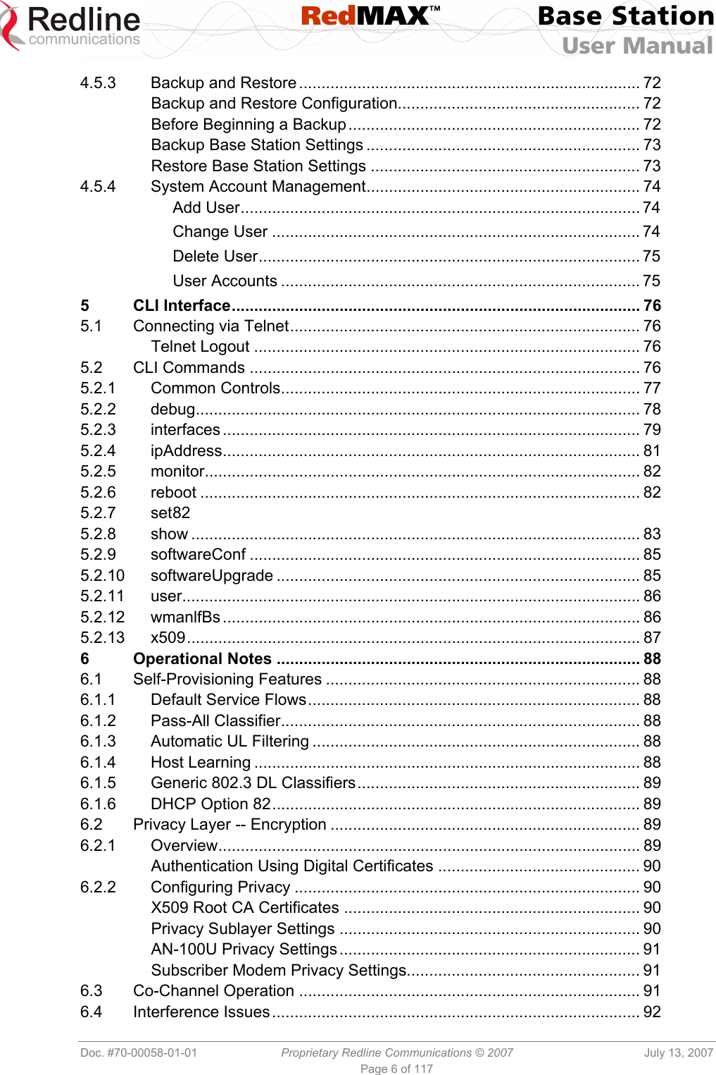
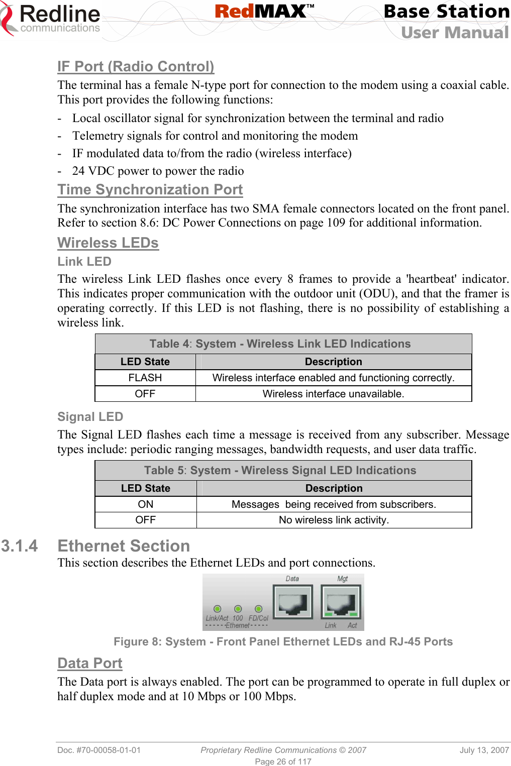
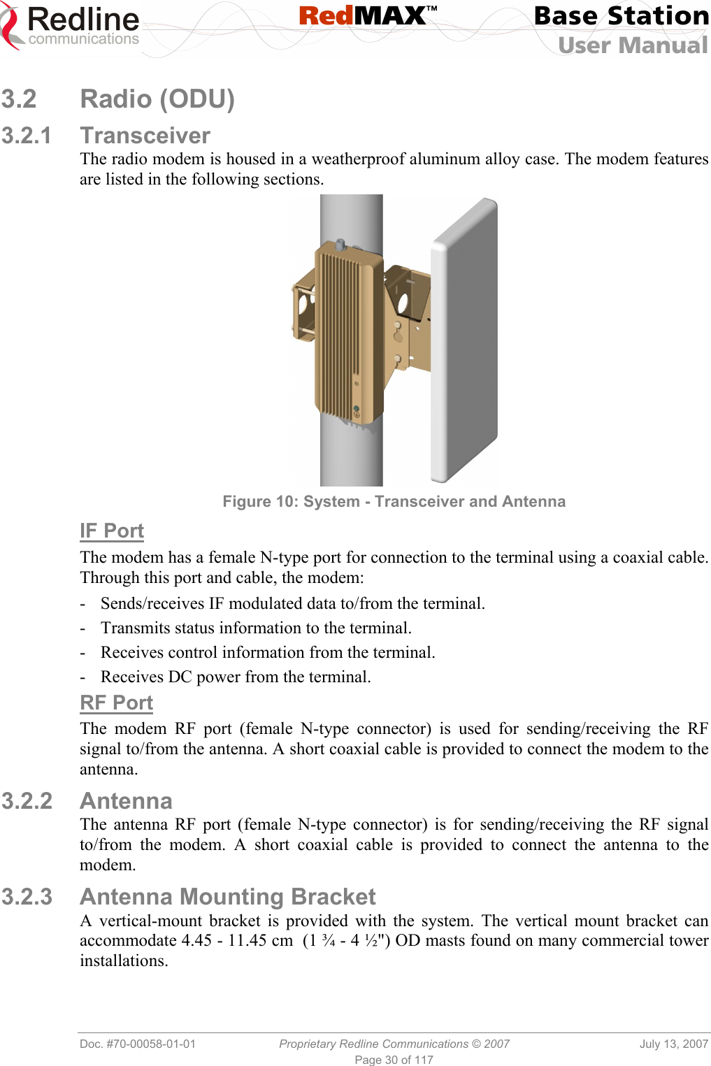
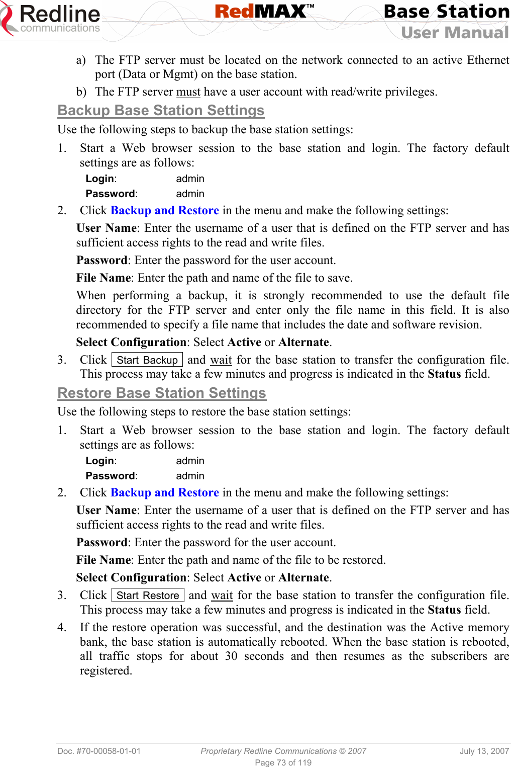
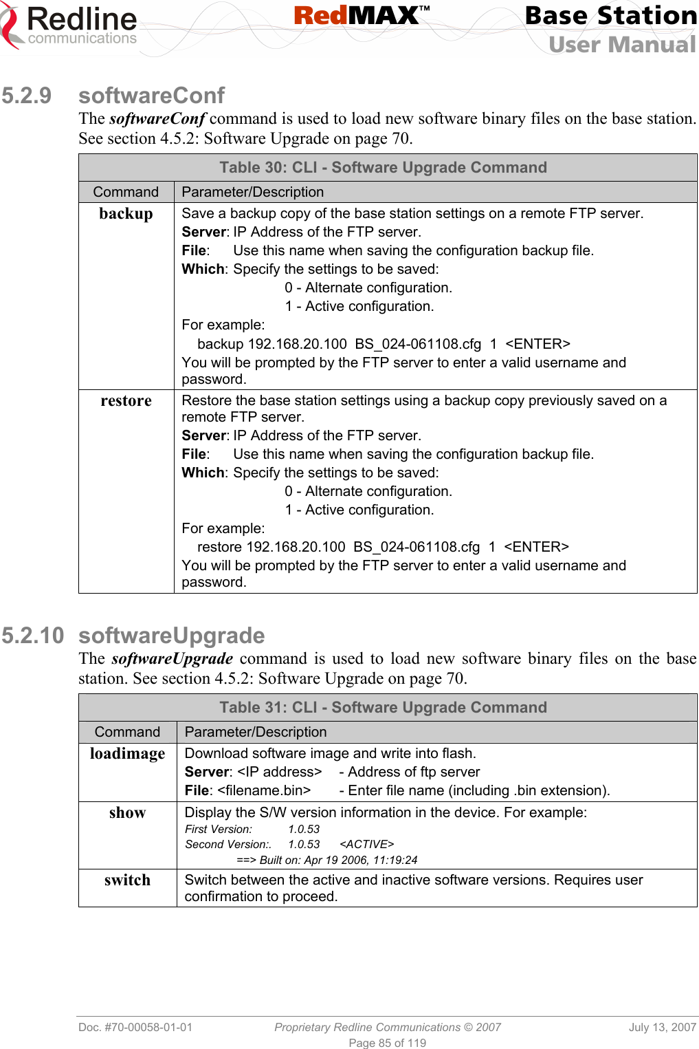
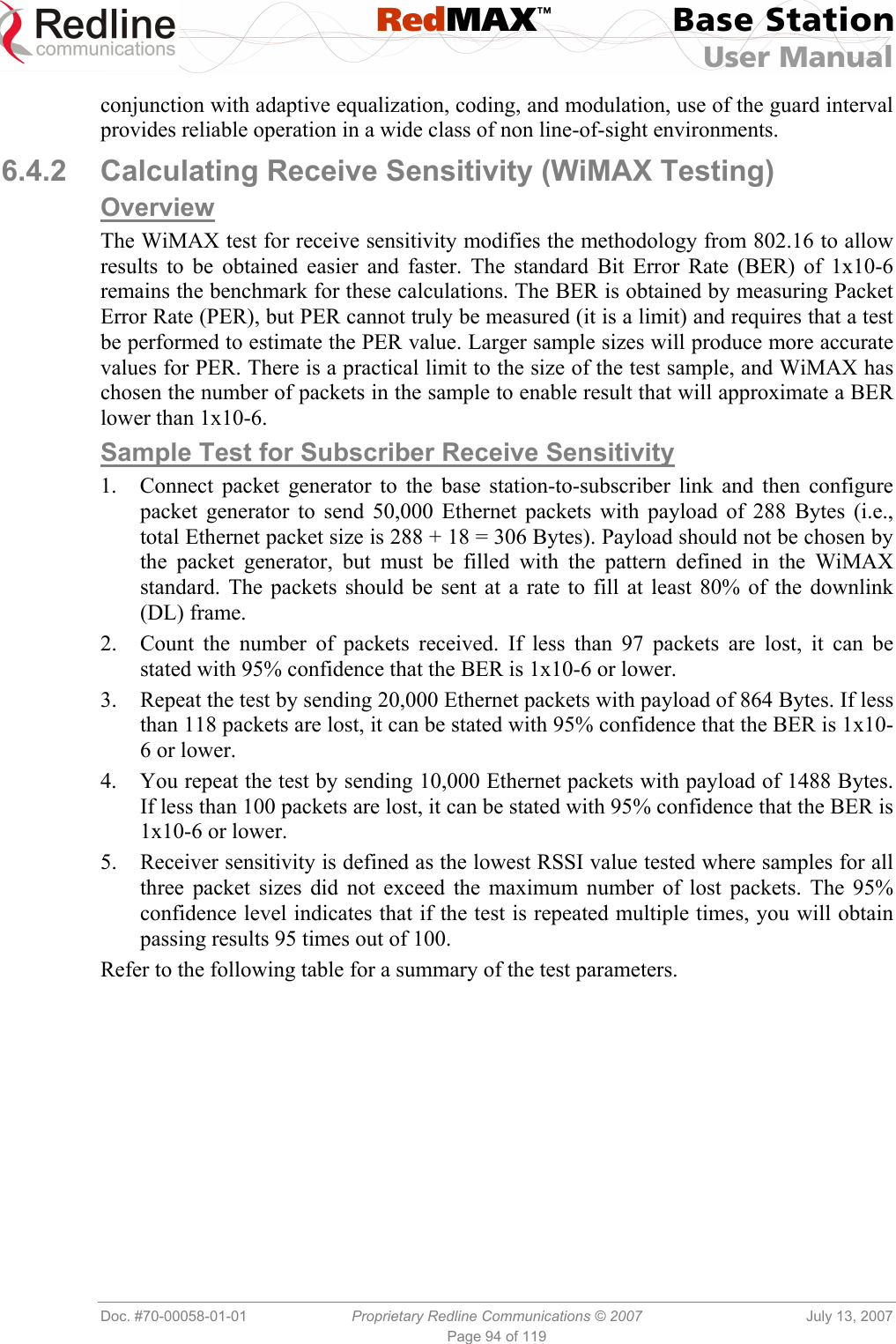
![RedMAX™ Base Station User Manual Doc. #70-00058-01-01 Proprietary Redline Communications © 2007 July 13, 2007 Page 36 of 117 DL Bandwidth Usage [%]: Current usage of downlink channel. Reference RSS [dBm]: The Reference RSS setting is the target value for average Received Signal Strength (RSS) for subscribers RF signals received by the base station. This target value allows automatic adjustment of the subscriber Tx power for optimum performance with the minimum of RF interference. The suggested default setting for the Reference RSS value is: Channel Size Initial Setting 3.5 MHz -75 dBm 7.0 MHz -72 dBm These are the suggested initial settings; adjustments to this target value must be made based on the individual RF characteristics of each deployed sector. The RSSI value (dBm) for each subscriber can be monitored using the base station SS Info screen (Web interface). Tx power adjustments are based on a number of factors, and differences of up to 7 dB may be observed between the Reference RSS setting and measured RSSI. RF Tx Power [dBm]: Radio transmission output power level. Traffic Uplink [kbps]: Rate of traffic received from subscribers. BW Margin Uplink [kbps]: Uplink bandwidth available that can be scheduled by the base station (based on the minimum traffic rate settings for all active service flows). Registered SS's: Number of subscribers currently registered with the base station. SC Synchro Status: Status of the base station time synchronization. Refer to the RedMAX Base Station Installation Guidelines for complete details of the synchronization feature. No Synch - base station is not using synchronization. Master with GPS Synchro - base station is Master and is synchronized to an external GPS clock. Master - base station is Master and is using internal clock. Slave - base station is Slave. Backup Slave - base station is Backup Slave and will assume Master operations if Master is unavailable. ODU Temperature [Celsius]: Internal temperature of the modem. Fans Status: Display the status of the system cooling fans. oneFanOn - A single cooling fan is operating. twoFansOn - Both cooling fans are operating. Active UL Service Flows: Number of currently active uplink service flows. UL SMC Rate [kbps]: Data rate for uplink channel. UL Bandwidth Usage [%]: Current usage of uplink channel. Noise Level [dBm]: Indicates the noise level. This value is measured by sampling the radio receiver input during idle periods (base station and subscribers are not transmitting) and provides an indication of the average level of interference in the sector.](https://usermanual.wiki/Redline-Communications/AN100UA/User-Guide-818393-Page-36.png)
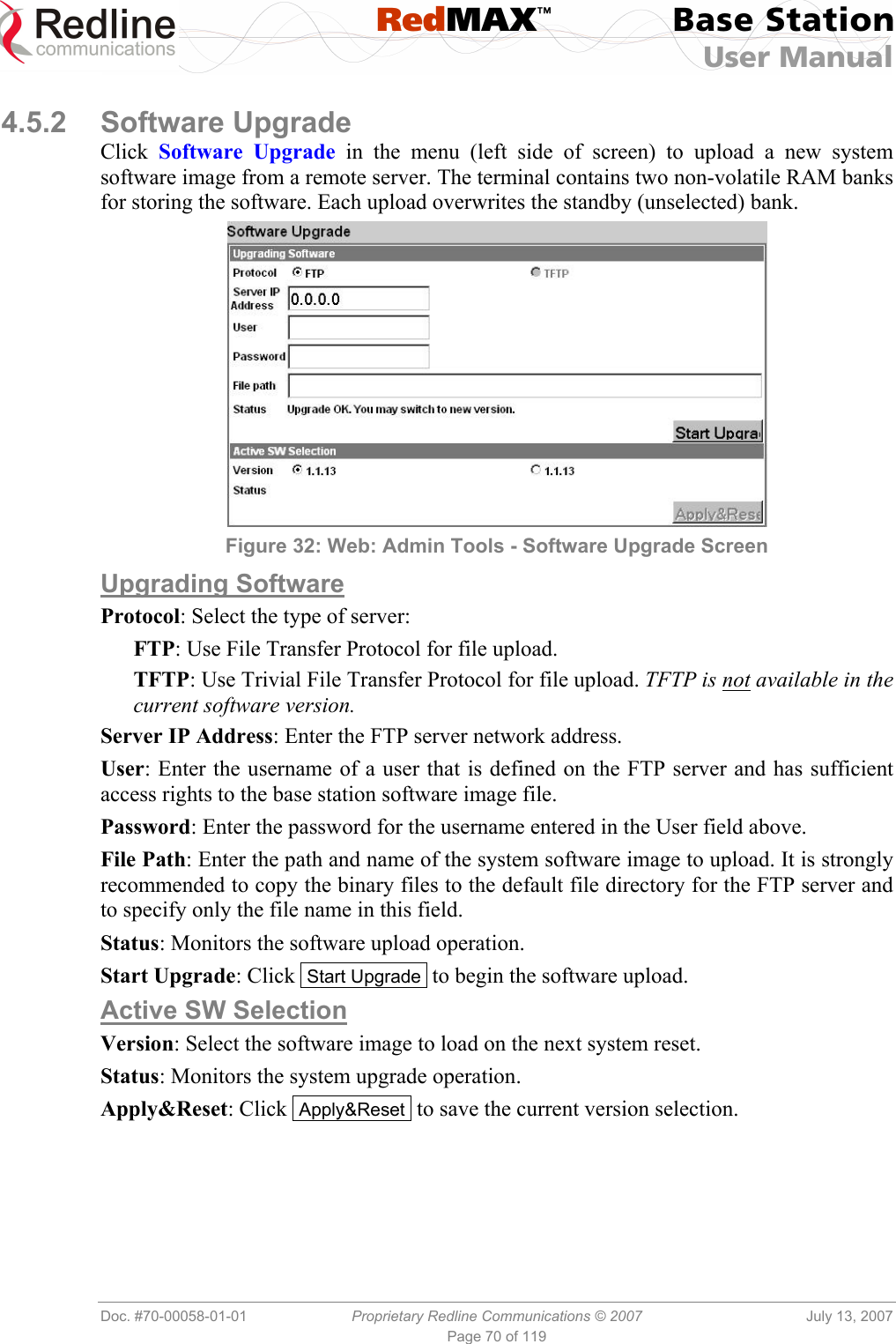
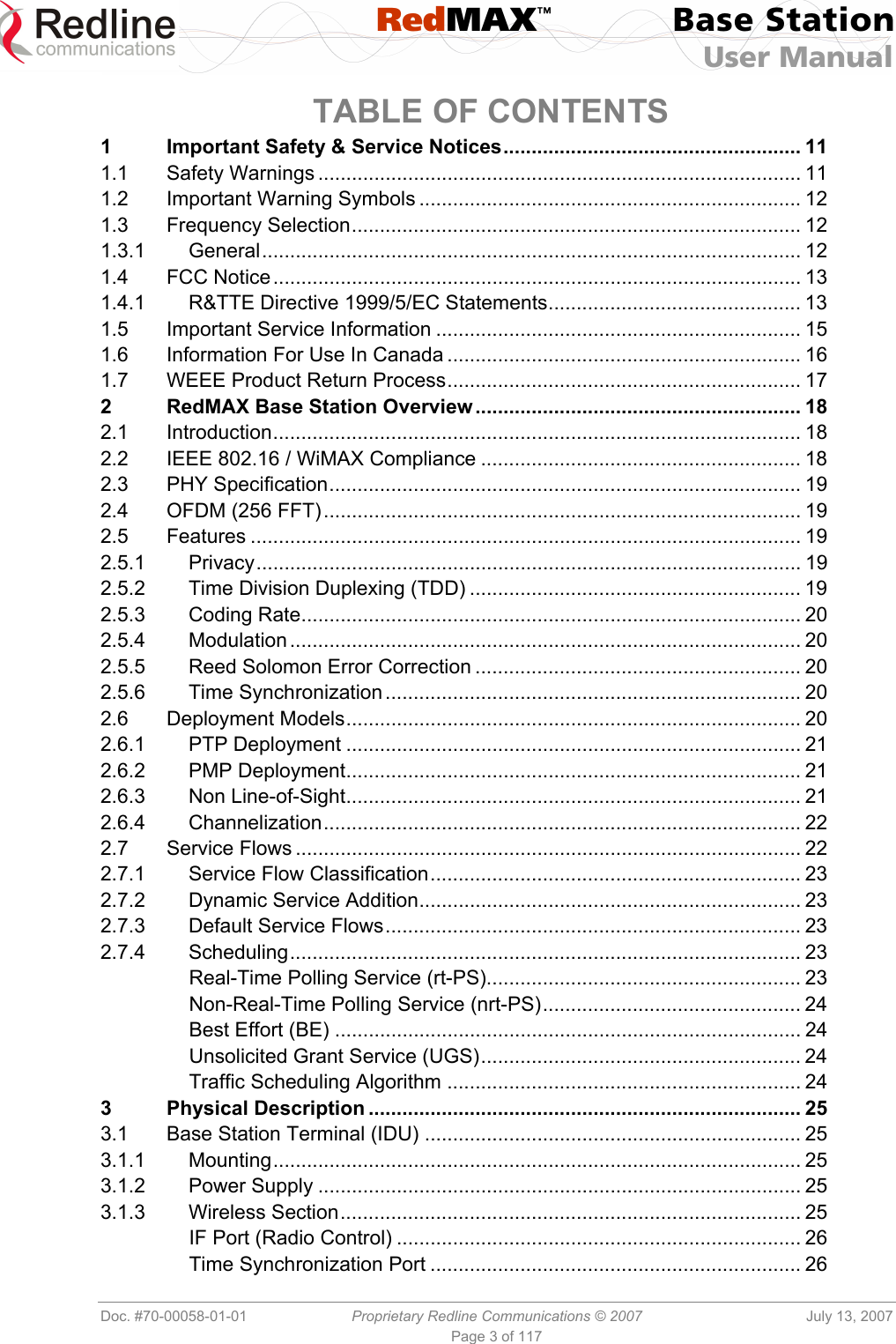
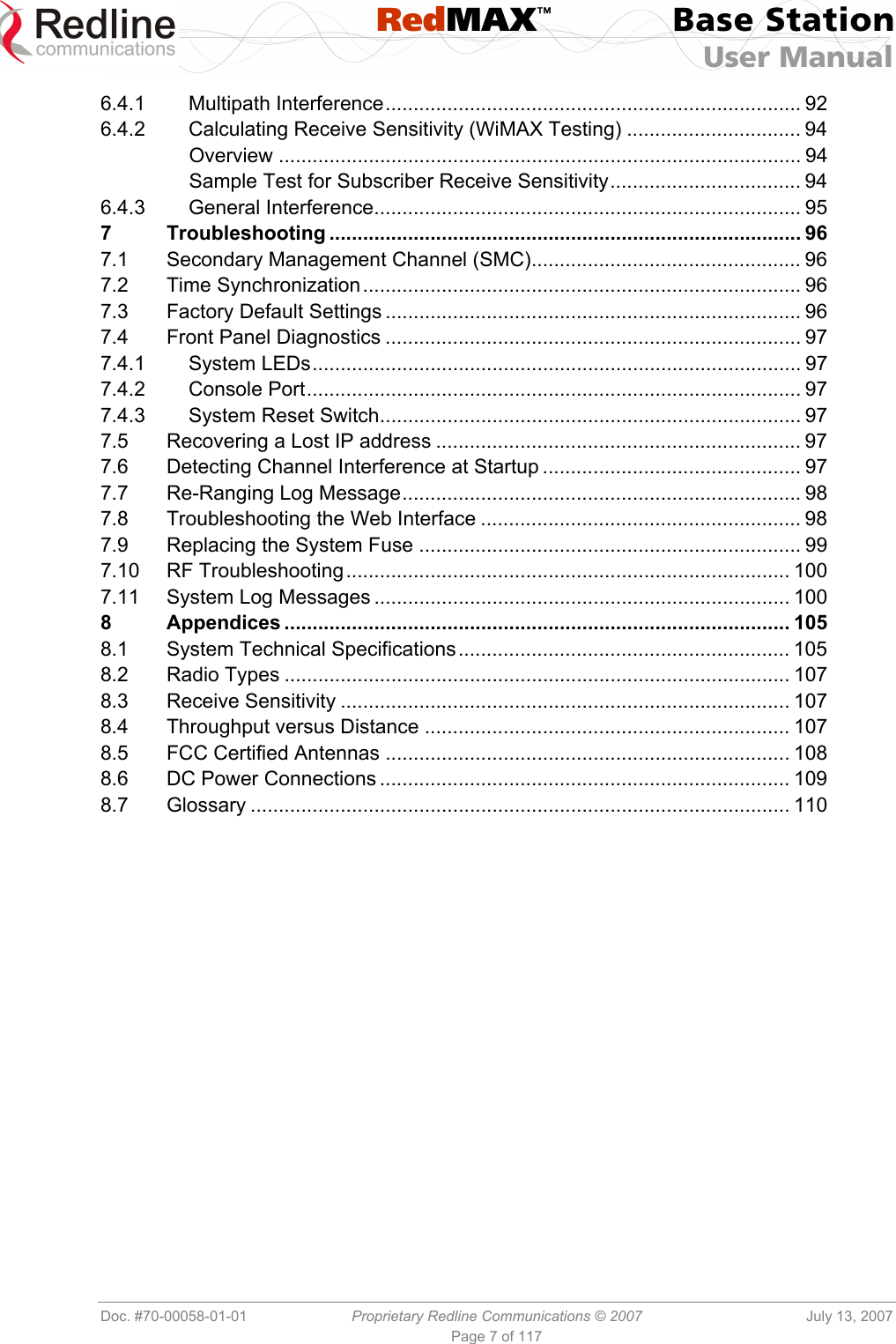
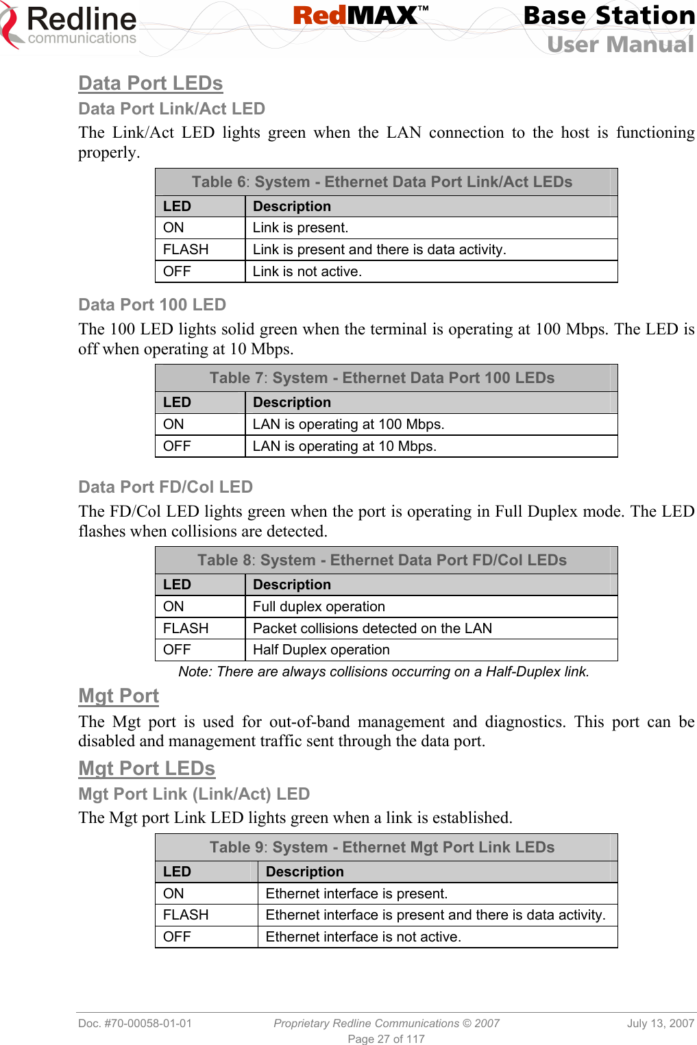
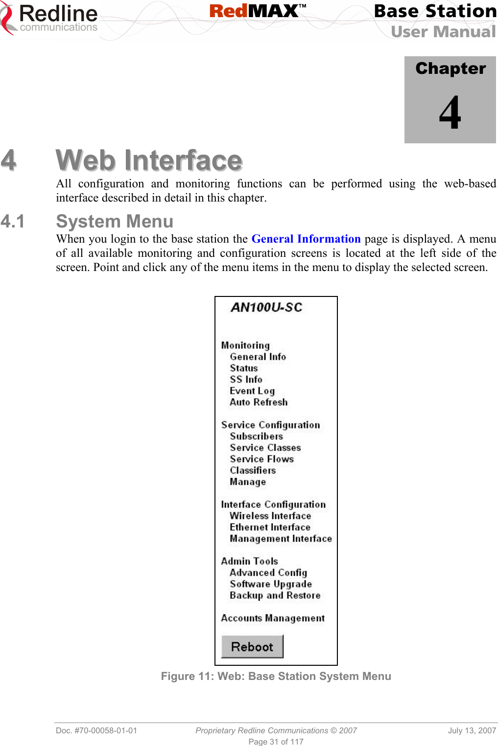
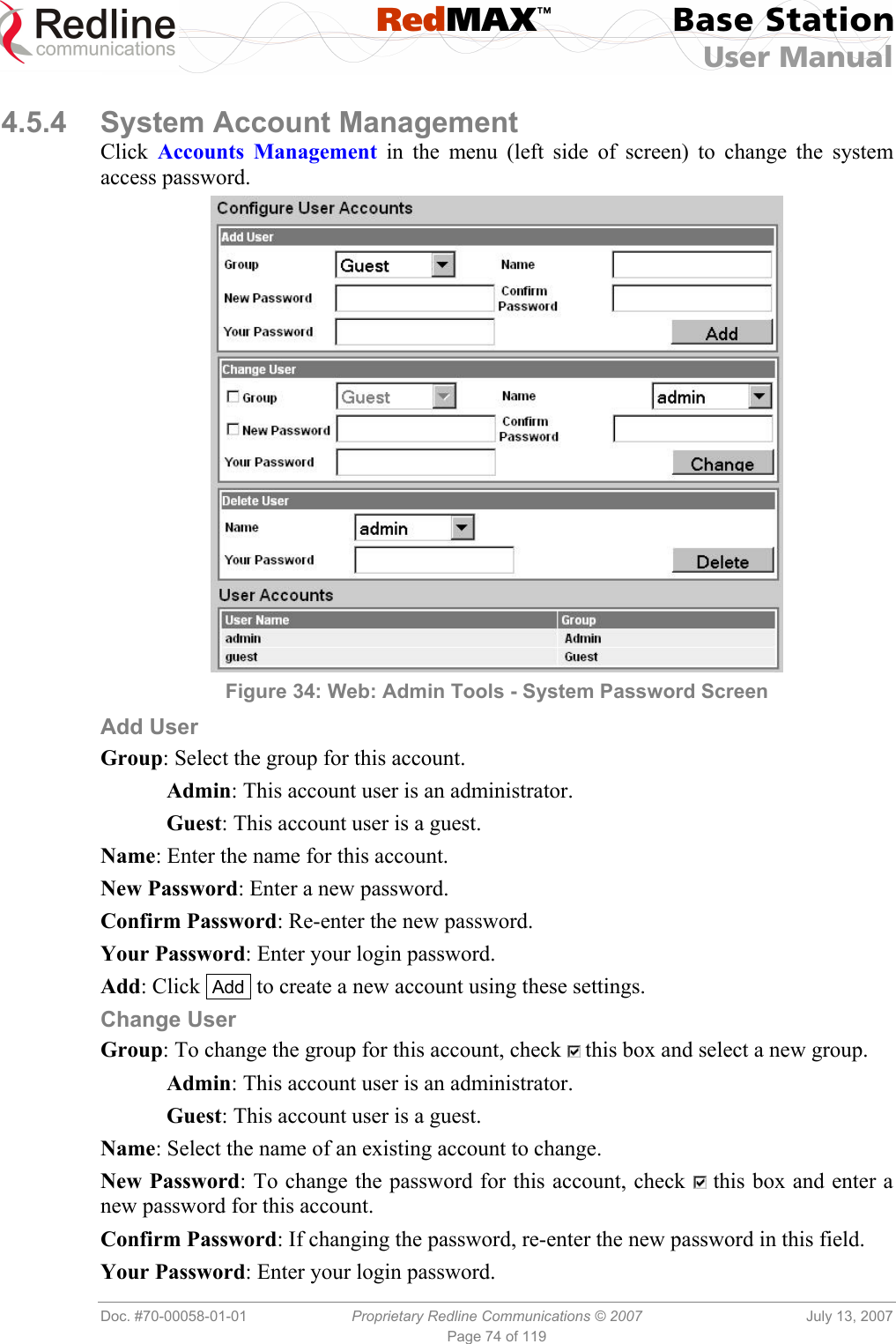
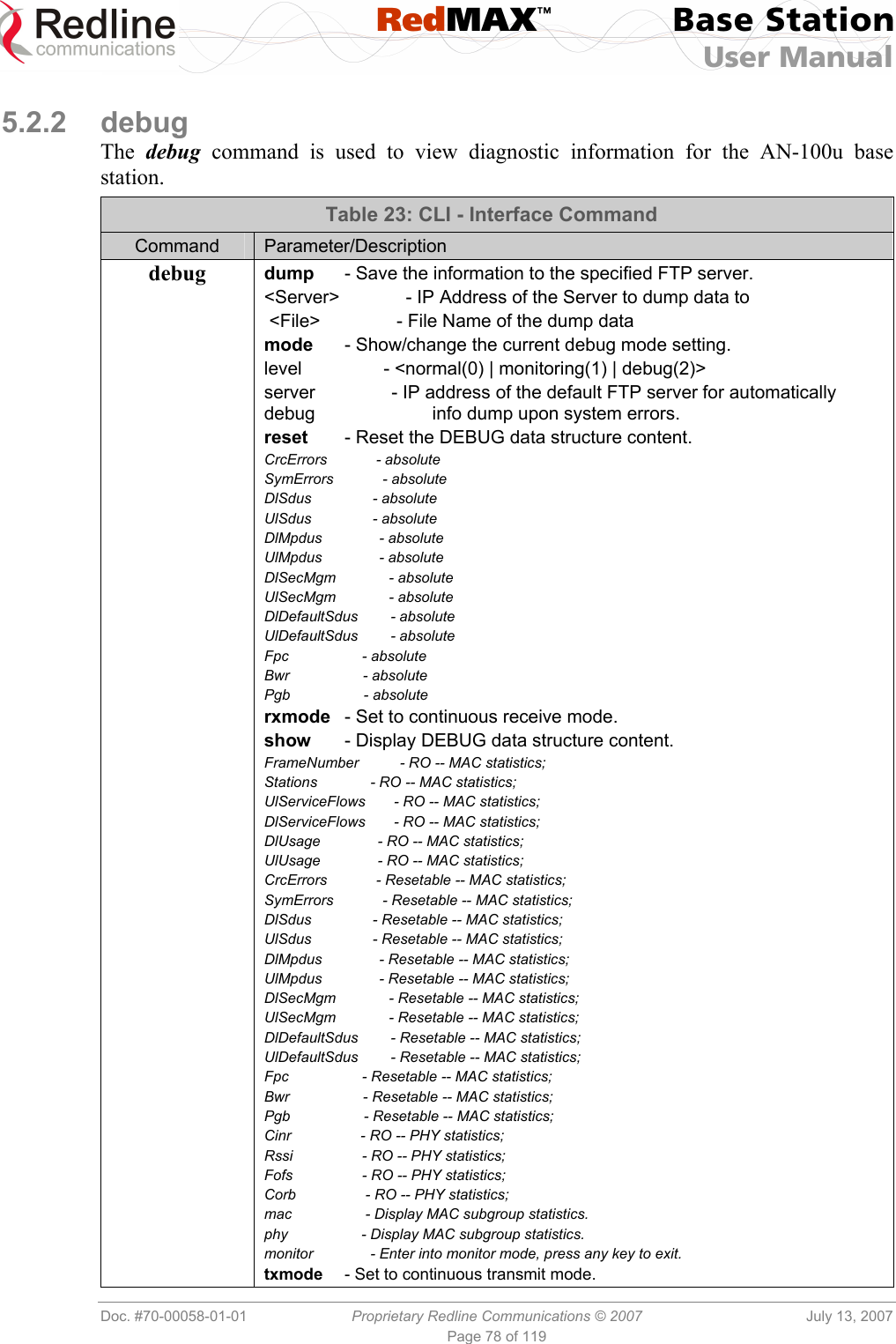
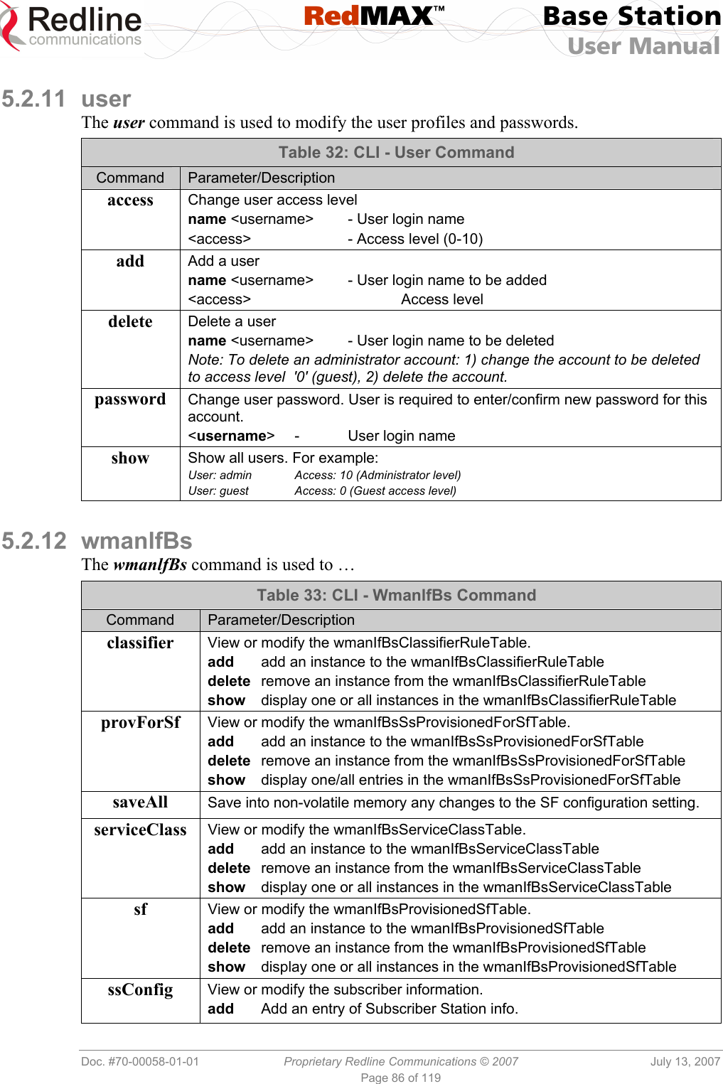
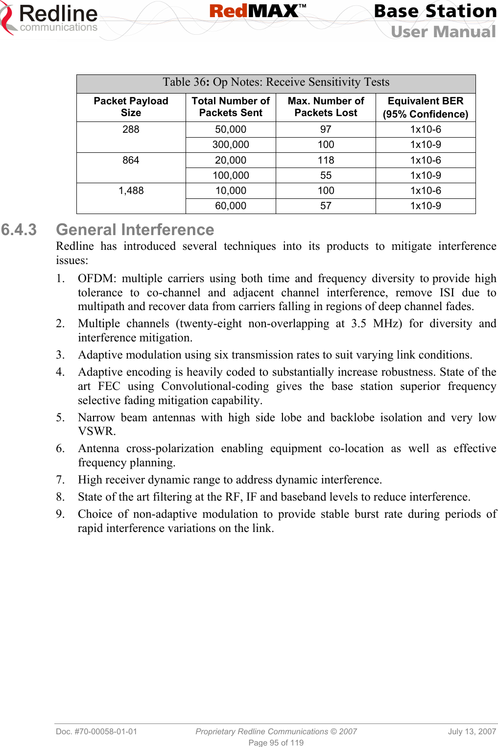
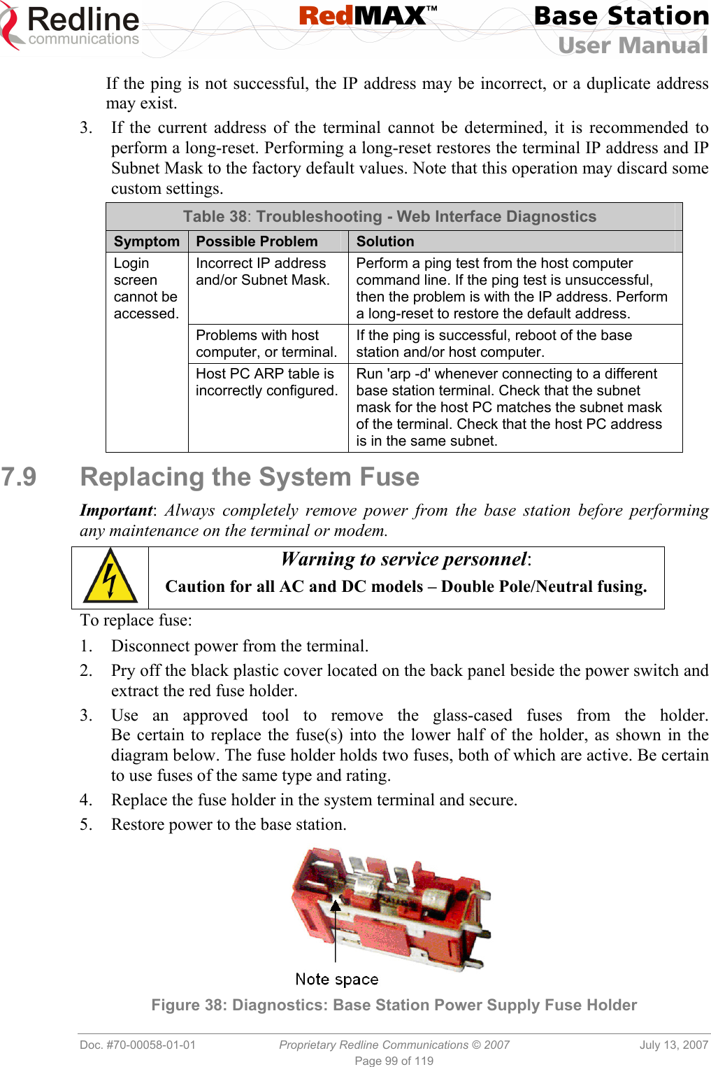
![RedMAX™ Base Station User Manual Doc. #70-00058-01-01 Proprietary Redline Communications © 2007 July 13, 2007 Page 71 of 119 Before Beginning the Upgrade Use the following procedures to upgrade the base station. The following items must be addressed before beginning the upgrade: 1. You must obtain the latest base station binary files. You must copy the binary files into the default file location for the FTP server. You can not specify a 'path' in the upgrade dialog. 2. The base station performs all software upgrades using an FTP server: a) The FTP server must be located on the network connected to an active Ethernet port (Data or Mgmt) on the base station. b) The FTP server must have a user defined as follows: username: target password: secret Upgrade Base Station 1. Start a Web browser session to the base station and login. The factory default settings are as follows: Login: admin Password: admin 2. Click Software Upgrade in the left-hand menu and make the following settings: Protocol: FTP Server IP address: [enter address of FTP server] User: target Password: secret File Path: [Enter binary file name -- including .bin extension] 3. Click Upgrade button and wait for the base station to download and save the binary file. This process may take a few minutes. Progress is indicated in the Status field. The Status Screen displays 'Update OK' when the upgrade is complete. 4. In the Software Upgrade screen, Click radio to select the new version of software. Click Apply&Reset to activate the new software. Click Yes in the confirmation dialog. Note: When the base station is reset, all traffic stops for about 30 seconds and then resumes as the subscribers are registered.](https://usermanual.wiki/Redline-Communications/AN100UA/User-Guide-818393-Page-71.png)
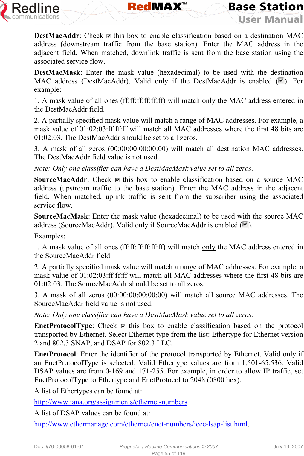
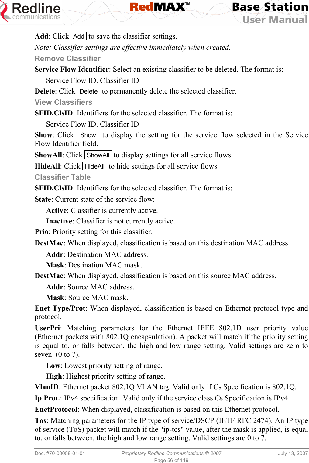
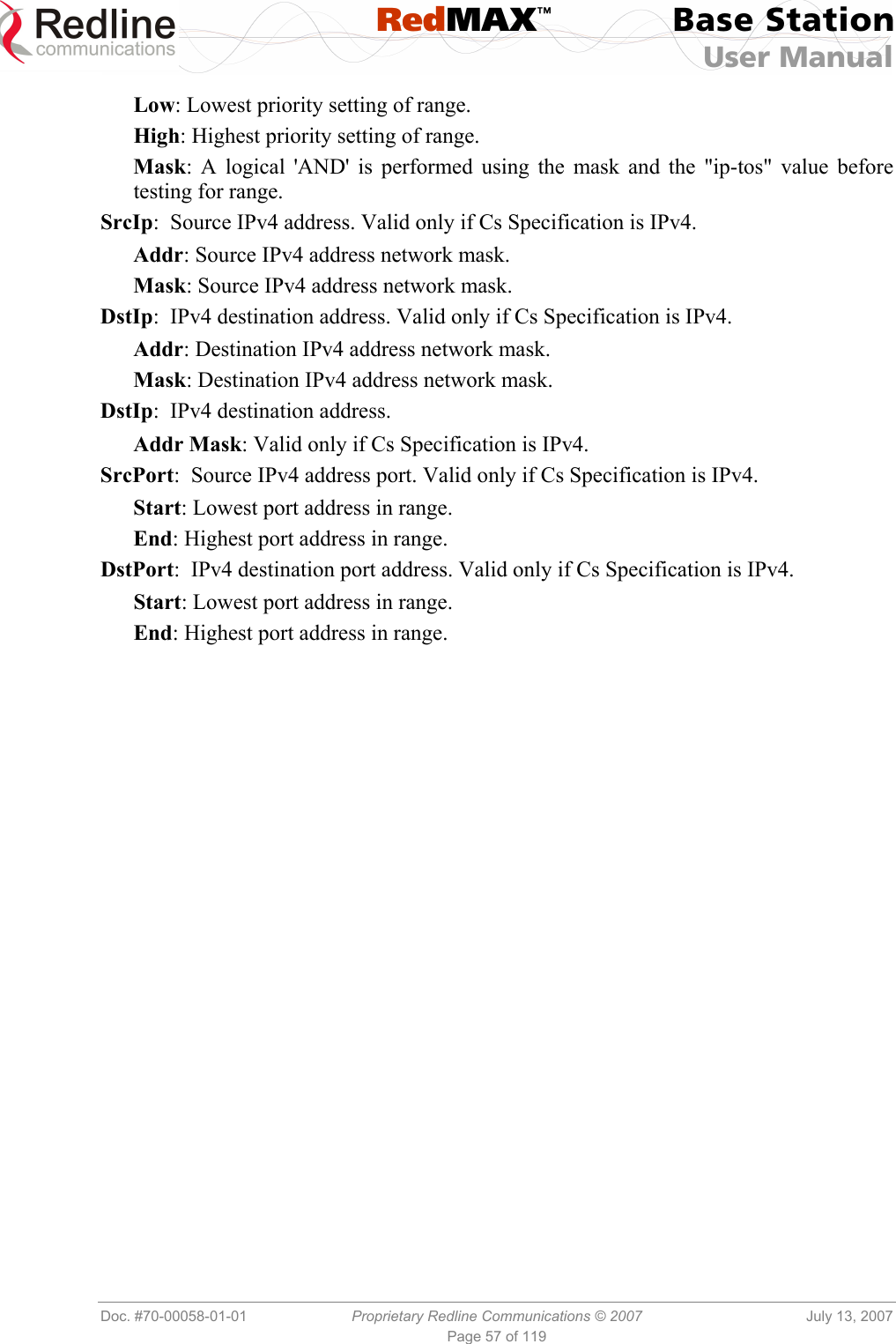
![RedMAX™ Base Station User Manual Doc. #70-00058-01-01 Proprietary Redline Communications © 2007 July 13, 2007 Page 89 of 119 6.1.5 Generic 802.3 DL Classifiers When host learning is enabled, 802.3 classifiers created for downlink service flows will be 'generic' type. The generic type 802.3 classifier allows all downlink Ethernet traffic addressed to any of the learned hosts on the associated subscriber. Only the priority may be adjusted on generic 802.3 classifiers. 6.1.6 DHCP Option 82 The DHCP option 82 support can be used by equipment upstream of the RedMAX base station to uniquely identify when customer equipment located behind a subscriber issues a request for network access (DHCP request for an IP address). This information, used in combination with other network notification messages, allows network operators to be informed when customers activate self-install CPEs. Operations can then take manual or automated actions to authorize and activate the services for this subscriber. The format of Relay Agent Option 82 option is as follows: Circuit ID: MAC address of base station. Remote ID: MAC address of subscriber. GiAddr: Management IP address of base station (if added by upstream equipment). Note: The subscriber CLI control 'dhcpRelayAgent' must be enabled prior to using the Option 82 feature. 6.2 Privacy Layer -- Encryption 6.2.1 Overview All RedMAX equipment is hardware enabled to support the privacy sub-layer as defined in 802.16-2004. The process of modem authentication and message exchange for user traffic encryption is described fully in the 802.16-2004. The Privacy Sub-layer can be enabled on a individual subscribers. This release supports user traffic encryption through the DES cryptographic suite only, with the Traffic Encryption Key secured to a 3DES level. Encryption must be enabled separately for the AN-100U and each participating subscriber. Authentication and registration are part of the 802.16 MAC common part sublayer. Authentication is based on the use of PKI technology-based X.509 digital certificates. Each wireless subscriber access modem will contain one built-in certificate for itself and another for its manufacturer. These certificates allow the customer modem to uniquely authenticate itself with the base station. The base station can then verify that the customer modem is authorized to receive service. If the database lookup succeeds, the base station sends the customer modem an encrypted authorization key, using the customer modem’s public key. This authorization key is used to encrypt and protect any transmissions that follow. The authentication process ensures the subscriber modem is an authentic device and not a rogue that was brought into the wireless sector area. For authentication the devices use X.509 digital certificates [IETF RFC 3280] together with RSA public-key encryption algorithm. At the end of the authentication, process the device has a shared key with its peer known as AK (Authentication Key). This Key is used to derive the TEK.](https://usermanual.wiki/Redline-Communications/AN100UA/User-Guide-818393-Page-89.png)
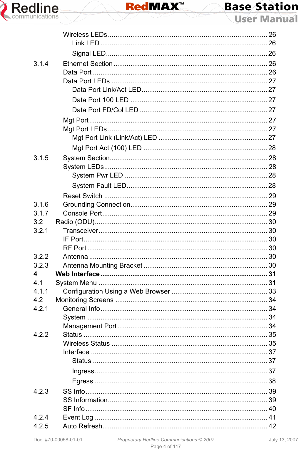
![RedMAX™ Base Station User Manual Doc. #70-00058-01-01 Proprietary Redline Communications © 2007 July 13, 2007 Page 97 of 119 7.4 Front Panel Diagnostics Figure 37: Diagnostics: Base Station Front Panel View 7.4.1 System LEDs The front panel of the terminal includes a number of LEDs to monitor operation of the system and assist troubleshooting. Refer to section 3: Physical Description on page 25. 7.4.2 Console Port The front panel includes the Console port. Use the CLI commands to interrogate the base station status and program most system settings. 7.4.3 System Reset Switch Throughout this section, reference is made to the reset switch, which is a micro-switch recessed in the front panel in the system block. Use a small narrow object, such as a paper clip, to access the switch. Depressing the reset switch for less than five seconds activates a short-reset. This is equivalent to turning the terminal off and on. Statistical values are reset. The selected system software image is loaded. Depressing the front panel reset switch for more than five seconds activates a long-reset. A long-reset reloads the factory defaults for the IP Address, IP subnet mask, and password and then resets the system. Statistical values are reset. The selected system software image is loaded. 7.5 Recovering a Lost IP address Use a DB-9 serial cable to access the base station serial console. The configuration of the serial port should be 57,600 bps, no parity, 8 data bits, 1 stop bit. Once connected, type in the command ifShow and read the value of inet under the idt interface. 7.6 Detecting Channel Interference at Startup Following a power-cycle or reboot, the base station monitors the RF Channel to detect interference on the uplink channel. The transceiver is set to receive mode and the PHY is programmed to receive a long preamble from a WiMAX base station. If no preamble is detected during the one-second interval, the channel is considered free of interference from other WiMAX equipment. If a long preamble is received, the base station continues to monitors the channel for an additional three seconds. If an 802.16d DL-Map is received, the following message will be entered into the event log: WARNING: RF Channel Conflict with [BS Id] This message in the event log indicates that another base station has been detected using the following RF-PHY characteristics:](https://usermanual.wiki/Redline-Communications/AN100UA/User-Guide-818393-Page-97.png)
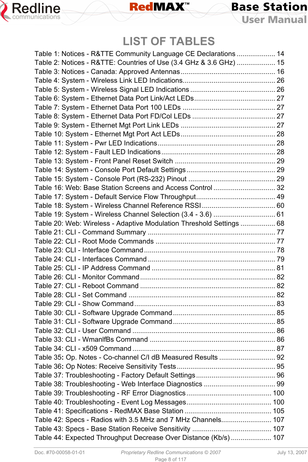
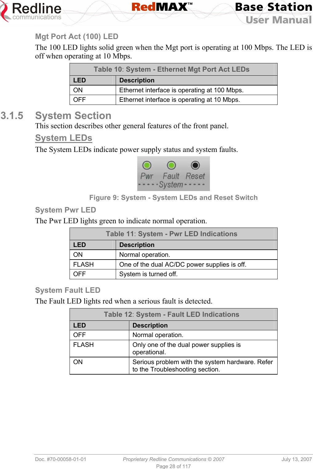
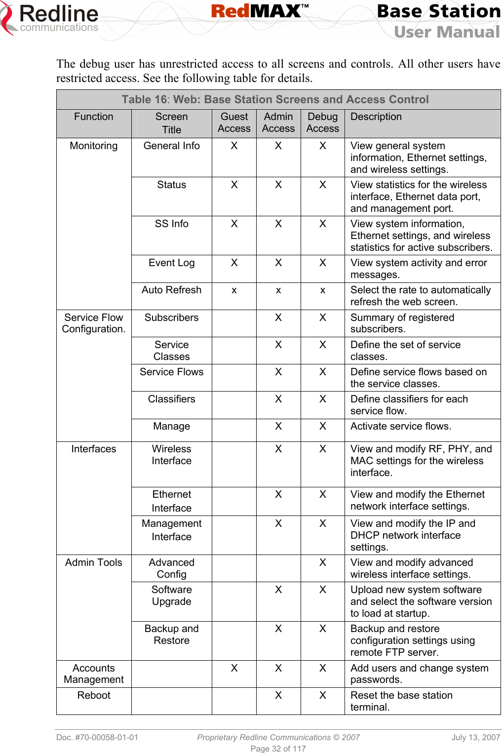
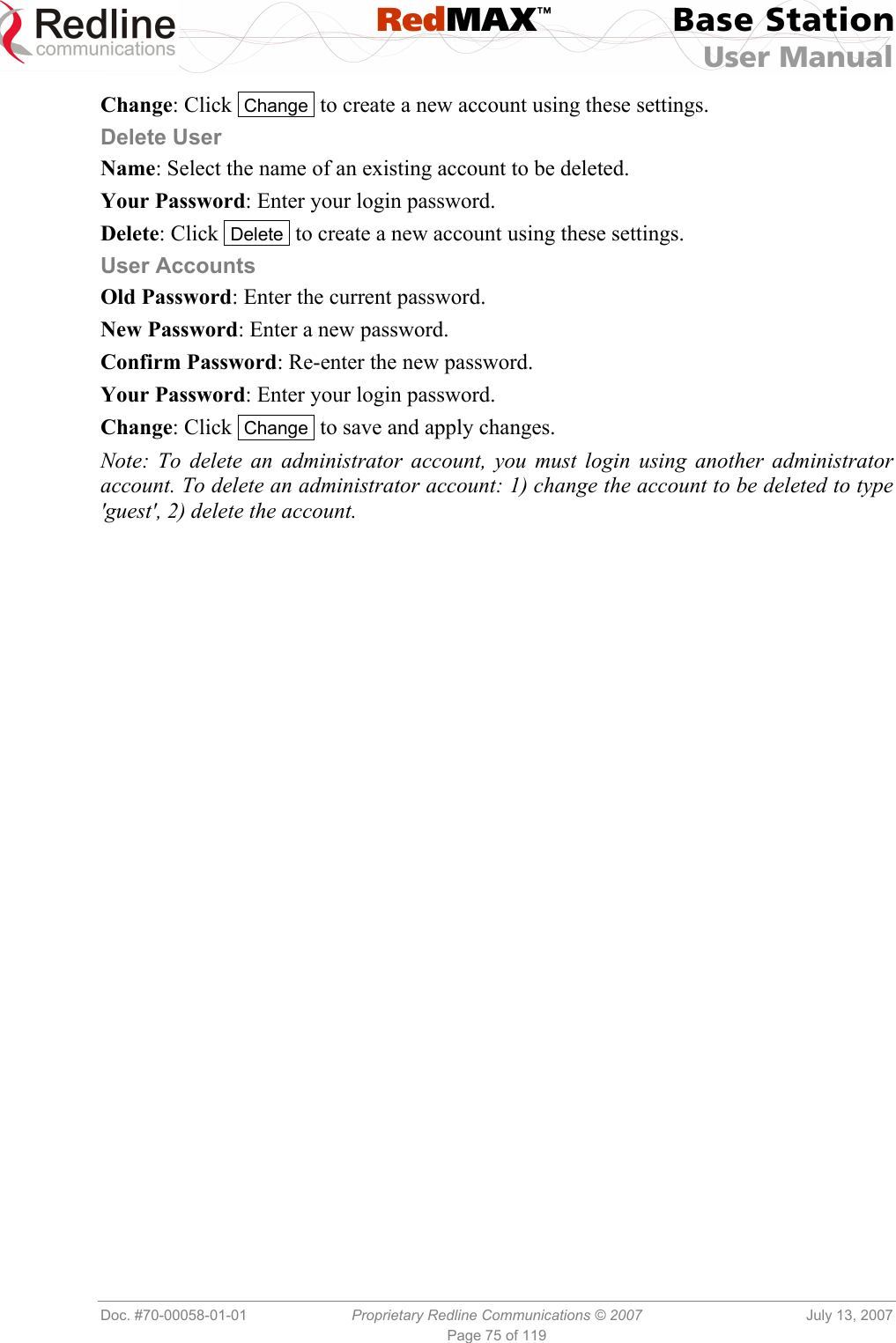
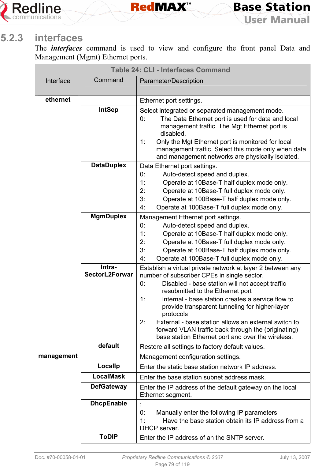
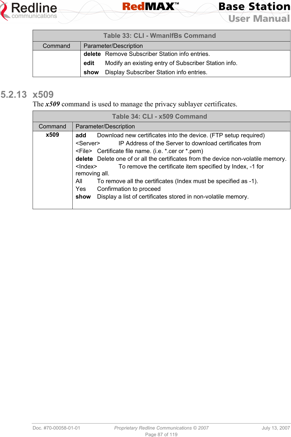
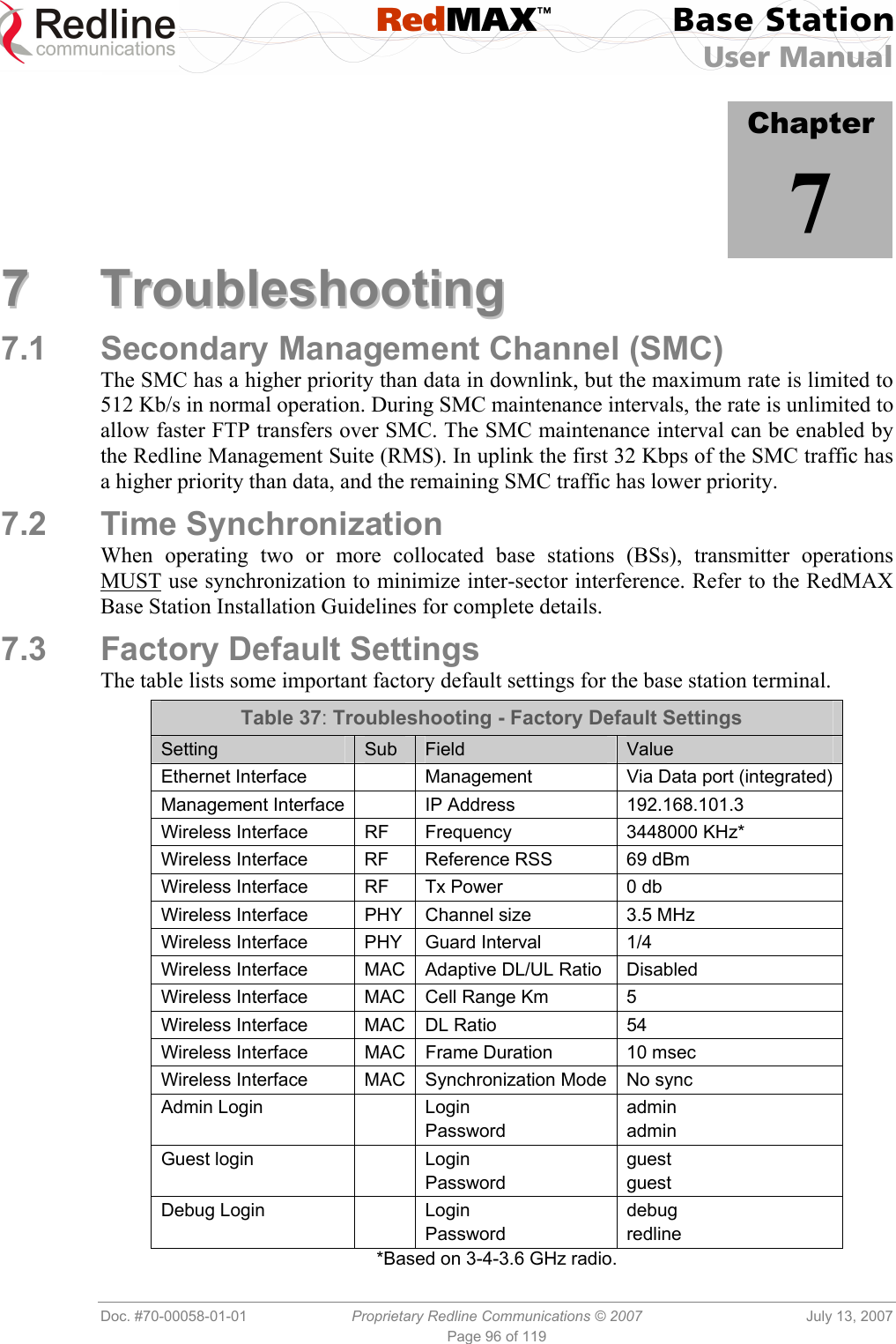
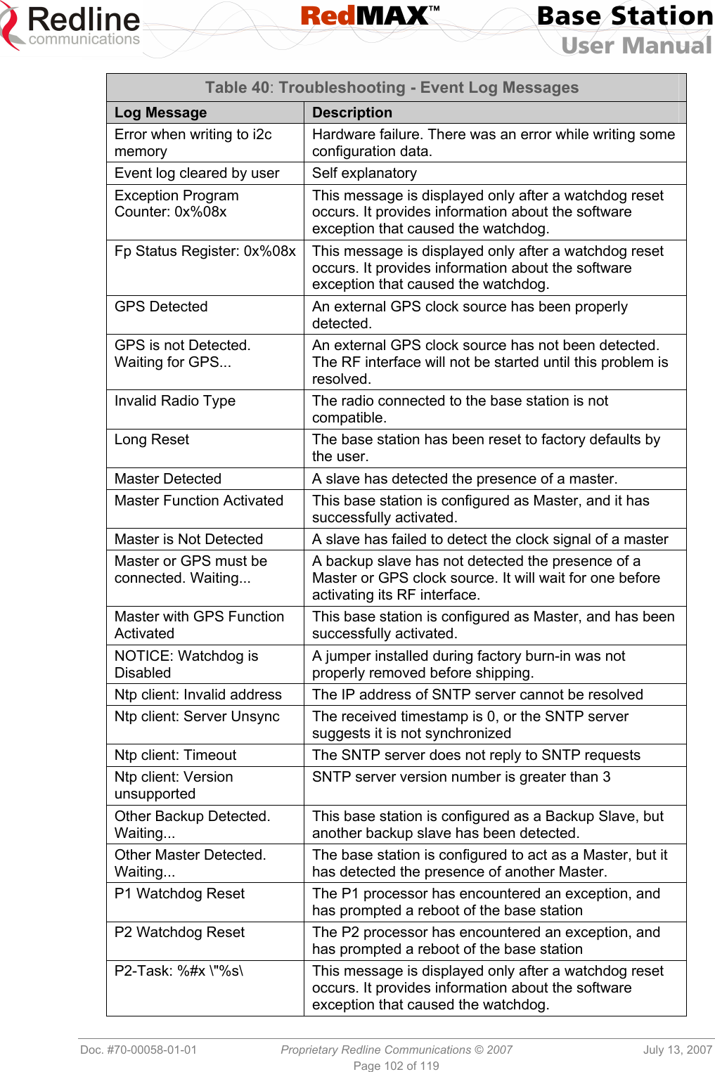
![RedMAX™ Base Station User Manual Doc. #70-00058-01-01 Proprietary Redline Communications © 2007 July 13, 2007 Page 100 of 119 7.10 RF Troubleshooting The terminal monitors the status of the outdoor modem unit and reports any fault conditions in the system event log. The following table lists the general fault conditions reported by the terminal. Table 39: Troubleshooting - RF Error Diagnostics Error Type Description IF PLL Unlocked The PLL (Phase Locked Loop) section within the terminal experienced an error. The System Fault LED may light. Try resetting the unit. Communication Error Over IF Cable Communication between the terminal and the modem failed. Check the IF cable and connectors. Outdoor Unit Temperature is too High. Air Interface Disabled for 15 Minutes The internal temperature of the modem is above 82C (180°F). The modem shuts down to allow cooling. Outdoor Unit Power Supply Error Displays a fault in the modem power supply. This error could be due to a problem with the internal power supply or with the power source from the terminal. If the 'Low DC Voltage At Radio' error is also indicated, (see below) check the IF cable and connectors. If the 'Low DC Voltage At Radio' error is not indicated, the modem requires servicing. Outdoor Unit 24V Error The DC voltage at the modem (carried by the IF cable from the terminal) is lower than the required 24 VDC. Check the IF cable and connectors. The minimum required voltage for operation is 12 VDC. Air Interface Disabled The radio is disabled. Cable Compensation Failed The measured IF cable compensation is out of specification. Invalid Radio The attached radio is not compatible with this terminal/configuration. Outdoor Unit 3.3V Error The modem internal power supply is lower than the required 3.3 VDC. 7.11 System Log Messages Table 40: Troubleshooting - Event Log Messages Log Message Description Access Address : 0x%08x This message is displayed only after a watchdog reset occurs. It provides information about the software exception that caused the watchdog. Air Interface is Disabled The RF interface has been disabled by the user. Air Interface is Enabled The RF interface has been enabled by the user. Another Upgrade operation is currently running. Skip SNMP[CLI,WEB] upgrade The user has tried to initiate an upgrade while another upgrade is already in progress. The command has been ignored.](https://usermanual.wiki/Redline-Communications/AN100UA/User-Guide-818393-Page-100.png)
![RedMAX™ Base Station User Manual Doc. #70-00058-01-01 Proprietary Redline Communications © 2007 July 13, 2007 Page 101 of 119 Table 40: Troubleshooting - Event Log Messages Log Message Description Another Upgrade operation is currently running. Skip SNMP[CLI,WEB] synchronization The user has tried to synchronize the active and alternate images while a software upgrade is in progress. The command has been ignored. Another Upgrade operation is currently running. Skip SNMP[CLI,WEB] backup The user has tried to backup the active image to the alternate while a software upgrade is in progress. The command has been ignored. Another Upgrade operation is currently running. Skip SNMP[CLI,WEB] restore The user has tried to apply a configuration file to either the active or alternate images while a software upgrade is in progress. The command has been ignored. Another Upgrade operation is currently running. Skip switchover The user has tried to switch software versions while an upgrade is in progress. The command has been ignored. Backup Detected This base station is configured as Master, and it has detected the presence of a Backup Slave Backup Function Activated This base station is configured as a Backup Slave, and has been successfully activated Cable Compensation Ok. Value = [v] The attenuation of the IF cable is within operating parameters. Cause Register: 0x%08x This message is displayed only after a watchdog reset occurs. It provides information about the software exception that caused the watchdog. CRITICAL: Cable Compensation Failed The attenuation of the IF cable to the ODU is too high. CRITICAL: IF Cable Disconnected The IF cable between the base station IDU and ODU has been disconnected. CRITICAL: IF PLL Error The IF chain has encountered a PLL error. Communication with the ODU has been interrupted. CRITICAL: LO[X] Error There has been a hardware problem with Local Oscillator [X]. CRITICAL: ODU Temperature is too High The operating temperature of the base station ODU is too high to continue operation. The IDU will temporarily suspend operation to avoid damage. CRITICAL: Radio Reference Frequency Error There has been a hardware problem with the synchronization of the ODU’s reference frequency. CRITICAL: Rx IF PLL Error The IF chain has encountered a PLL error. Communication with the ODU has been interrupted. Eep Configuration checksum error. Parameters are reset to factory defaults. Force WD reset... Self explanatory Error address: 0x%08x, Error ID: 0x%04x This message is displayed only after a watchdog reset occurs. It provides information about the software exception that caused the watchdog. Error when reading from i2c memory Hardware failure. There was an error while reading some configuration data.](https://usermanual.wiki/Redline-Communications/AN100UA/User-Guide-818393-Page-101.png)
![RedMAX™ Base Station User Manual Doc. #70-00058-01-01 Proprietary Redline Communications © 2007 July 13, 2007 Page 103 of 119 Table 40: Troubleshooting - Event Log Messages Log Message Description Parameters are reset to factory defaults This message appears after the user has initiated a long-reset to factory defaults Power Supply [X] is On Where X is either A or B. This signifies that the relevant power supply has been detected and is properly supplying power to the base station Radio Type [XX]: TBXXXXFX This message is simply a confirmation of the type of radio connected to the IDU. It should match with the radio type printed on the ODU’s sticker. RedMax base station Ver. X.X.X started System startup message. Reference Clock Calibration Done The reference clock calibration procedure initiated by the user has been completed. Reference Clock Calibration Failed The reference clock calibration procedure initiated by the user has failed. Restore configuration into active image The user-provided configuration file has been applied to the active image Restore configuration into alternate image The user-provided configuration file has been applied to the alternate (non-active) image RF capabilities are changed. Check RF and PHY parameters and activate again the RF interface Self explanatory Status Register: 0x%08x This message is displayed only after a watchdog reset occurs. It provides information about the software exception that caused the watchdog. Synchronization Failed. Waiting for Synchronization Signal... A base station configured as Slave has detected the Master on reboot, but synchronization failed. It will wait and try again. Synchronization Lost A slave has previously synchronized with a Master, but since lost the signal and drifted out of phase. Synchronization of alternate completed successfully Software image and configuration have been applied to the alternate image, overwriting its previous contents. Synchronization of configurations not possible The synchronization of software and configuration from the active image to the alternate has failed. Synchronization Ok Synchronization with a Master or Backup Slave was successful. Synchronization Signal not Detected. Waiting... A base station configured as Slave cannot detect the synchronization Master. Synchronization with Backup Failed This base station is configured as Master. It has recently rebooted, detected the presence of a Backup Slave, but it has failed to resume control of the base station’s clock. Synchronization with Backup Ok This base station is configured as Master. It has recently rebooted, detected the presence of a Backup Slave, and successfully resumed control of the base station’s clock. Synchronization with GPS is Lost Synchronization with a previously detected external clock source has been lost](https://usermanual.wiki/Redline-Communications/AN100UA/User-Guide-818393-Page-103.png)
![RedMAX™ Base Station User Manual Doc. #70-00058-01-01 Proprietary Redline Communications © 2007 July 13, 2007 Page 104 of 119 Table 40: Troubleshooting - Event Log Messages Log Message Description Synchronization with GPS Ok Synchronization with an external GPS clock has been successfully completed. Synchronization with Master is Lost A backup slave has previously detected the presence of a master clock signal, and synchronized. It has since lost this signal. Synchronization with Master Ok A slave has successfully synchronized with a master’s clock signal Synchronization Signal Detected A Slave has detected the clock signal of a Master. Synchronization Signal not Detected A slave has previously synchronized with a Master, but has since lost the signal. WARNING: Clock Offset Close to End of Scale The reference clock calibration procedure initiated by the user has been completed, but the clock offset is at the boundaries of the base station’s capabilities WARNING: DL aggregated Guaranteed Rate exceeds Capacity The aggregate guaranteed minimum rates configured for service flows using RTPS and UGS scheduling exceeds the downlink capacity of the sector. WARNING: Indoor Unit Temperature > 65 Celsius The base station indoor unit has exceeded the recommended operating temperature. WARNING: ODU Temperature is [c] Celsius The operating temperature of the base station ODU is nearing the limit of its operating temperature. No action is taken. WARNING: Power Supply [X] is Off Where X is either A or B. This signifies that the relevant power supply has been detected, but it is not supplying power to the base station. WARNING: UL aggregated Guaranteed Rate exceeds Capacity The aggregate guaranteed minimum rates configured for service flows using RTPS and UGS scheduling exceeds the uplink capacity of the sector. WRONG CRC over I2C The stored interface configuration data has failed integrity check. WARNING: Unknown Interference was detected on the UL channel During startup, a long preamble was received but no DL-Map was detected the UL channel. See section 7.6: Detecting Channel Interference at Startup on page 97. WARNING: RF Channel Conflict with [BS Id] During startup, a long preamble and DL-Map were both detected on the UL channel. See section 7.6: Detecting Channel Interference at Startup on page 97.](https://usermanual.wiki/Redline-Communications/AN100UA/User-Guide-818393-Page-104.png)