Redline Communications AN100UA Wireless Access Base Station User Manual 70 00058 01 01
Redline Communications Inc. Wireless Access Base Station 70 00058 01 01
User Manual
Doc. #70-00058-01-01 Proprietary Redline Communications © 2007 July 13, 2007
Page 1 of 117
RedMAXTM
AN-100U Single Sector
Wireless Access Base Station
User Manual
RedMAX™
Base Station
User Manual
Doc. #70-00058-01-01 Proprietary Redline Communications © 2007 July 13, 2007
Page 2 of 117
Copyright Information
All rights reserved July 13, 2007. The information in this document is proprietary
to Redline Communications Inc. This document may not in whole or in part be
copied, reproduced, or reduced to any medium without prior consent, in writing,
from Redline Communications Incorporated.
Contact Information:
Redline Communications Inc.
302 Town Centre Blvd. Suite 100
Markham, ON
Canada L3R 0E8
Web Site: http://www.redlinecommunications.com
Sales Inquiries:
North American: nainfo@redlinecommunications.com
Toll-free sales: 1-866-633-6669
International: intlinfo@redlinecommunications.com
Support: www.redlinecommunications.com/support/support_portal.html
Document Control:
70-00058-01-01-RedMAX_BaseStation_AN-100U_User-FCC-20070713a.doc
Disclaimer
The statements, configurations, technical data, and recommendations in this document
are believed to be accurate and reliable, but are presented without express or implied
warranty. Additionally, Redline makes no representations or warranties, either expressed
or implied, regarding the contents of this product. Redline Communications shall not be
liable for any misuse regarding this product. The information in this document is subject
to change without notice.

RedMAX™
Base Station
User Manual
Doc. #70-00058-01-01 Proprietary Redline Communications © 2007 July 13, 2007
Page 3 of 117
TABLE OF CONTENTS
1 Important Safety & Service Notices..................................................... 11
1.1 Safety Warnings ...................................................................................... 11
1.2 Important Warning Symbols .................................................................... 12
1.3 Frequency Selection................................................................................ 12
1.3.1 General................................................................................................ 12
1.4 FCC Notice.............................................................................................. 13
1.4.1 R&TTE Directive 1999/5/EC Statements............................................. 13
1.5 Important Service Information ................................................................. 15
1.6 Information For Use In Canada ............................................................... 16
1.7 WEEE Product Return Process............................................................... 17
2 RedMAX Base Station Overview .......................................................... 18
2.1 Introduction.............................................................................................. 18
2.2 IEEE 802.16 / WiMAX Compliance ......................................................... 18
2.3 PHY Specification.................................................................................... 19
2.4 OFDM (256 FFT)..................................................................................... 19
2.5 Features .................................................................................................. 19
2.5.1 Privacy................................................................................................. 19
2.5.2 Time Division Duplexing (TDD) ........................................................... 19
2.5.3 Coding Rate......................................................................................... 20
2.5.4 Modulation........................................................................................... 20
2.5.5 Reed Solomon Error Correction .......................................................... 20
2.5.6 Time Synchronization.......................................................................... 20
2.6 Deployment Models................................................................................. 20
2.6.1 PTP Deployment ................................................................................. 21
2.6.2 PMP Deployment................................................................................. 21
2.6.3 Non Line-of-Sight................................................................................. 21
2.6.4 Channelization..................................................................................... 22
2.7 Service Flows .......................................................................................... 22
2.7.1 Service Flow Classification.................................................................. 23
2.7.2 Dynamic Service Addition.................................................................... 23
2.7.3 Default Service Flows.......................................................................... 23
2.7.4 Scheduling........................................................................................... 23
Real-Time Polling Service (rt-PS)........................................................ 23
Non-Real-Time Polling Service (nrt-PS).............................................. 24
Best Effort (BE) ................................................................................... 24
Unsolicited Grant Service (UGS)......................................................... 24
Traffic Scheduling Algorithm ............................................................... 24
3 Physical Description ............................................................................. 25
3.1 Base Station Terminal (IDU) ................................................................... 25
3.1.1 Mounting.............................................................................................. 25
3.1.2 Power Supply ...................................................................................... 25
3.1.3 Wireless Section.................................................................................. 25
IF Port (Radio Control) ........................................................................ 26
Time Synchronization Port .................................................................. 26

RedMAX™
Base Station
User Manual
Doc. #70-00058-01-01 Proprietary Redline Communications © 2007 July 13, 2007
Page 4 of 117
Wireless LEDs..................................................................................... 26
Link LED ......................................................................................... 26
Signal LED...................................................................................... 26
3.1.4 Ethernet Section.................................................................................. 26
Data Port ............................................................................................. 26
Data Port LEDs ................................................................................... 27
Data Port Link/Act LED................................................................... 27
Data Port 100 LED ......................................................................... 27
Data Port FD/Col LED .................................................................... 27
Mgt Port............................................................................................... 27
Mgt Port LEDs ..................................................................................... 27
Mgt Port Link (Link/Act) LED .......................................................... 27
Mgt Port Act (100) LED .................................................................. 28
3.1.5 System Section.................................................................................... 28
System LEDs....................................................................................... 28
System Pwr LED ............................................................................ 28
System Fault LED........................................................................... 28
Reset Switch ....................................................................................... 29
3.1.6 Grounding Connection......................................................................... 29
3.1.7 Console Port........................................................................................ 29
3.2 Radio (ODU)............................................................................................ 30
3.2.1 Transceiver.......................................................................................... 30
IF Port.................................................................................................. 30
RF Port ................................................................................................ 30
3.2.2 Antenna ............................................................................................... 30
3.2.3 Antenna Mounting Bracket .................................................................. 30
4 Web Interface......................................................................................... 31
4.1 System Menu .......................................................................................... 31
4.1.1 Configuration Using a Web Browser ................................................... 33
4.2 Monitoring Screens ................................................................................. 34
4.2.1 General Info......................................................................................... 34
System ................................................................................................ 34
Management Port................................................................................ 34
4.2.2 Status .................................................................................................. 35
Wireless Status ................................................................................... 35
Interface .............................................................................................. 37
Status ............................................................................................. 37
Ingress............................................................................................ 37
Egress ............................................................................................ 38
4.2.3 SS Info................................................................................................. 39
SS Information..................................................................................... 39
SF Info................................................................................................. 40
4.2.4 Event Log ............................................................................................ 41
4.2.5 Auto Refresh........................................................................................ 42

RedMAX™
Base Station
User Manual
Doc. #70-00058-01-01 Proprietary Redline Communications © 2007 July 13, 2007
Page 5 of 117
4.3 Creating Service Flows - Overview ......................................................... 43
4.3.1 Subscribers.......................................................................................... 44
Delete SS ....................................................................................... 45
Subscribers..................................................................................... 45
4.3.2 Service Classes................................................................................... 46
Service Class Configuration Screen.................................................... 46
Add a Service Class ....................................................................... 46
Delete a Service Class ................................................................... 48
View Service Class......................................................................... 48
4.3.3 Service Flows ...................................................................................... 49
Default UL/DL Service Flows.......................................................... 49
Add Service Flow............................................................................ 49
Delete SF (all associated Classifiers will be deleted) ..................... 52
Service Flows ................................................................................. 52
Service Flow Status Display ........................................................... 52
4.3.4 Classifiers............................................................................................ 54
Classifier Configuration Screen........................................................... 54
Add a Classifier .............................................................................. 54
Remove Classifier .......................................................................... 56
View Classifiers .............................................................................. 56
Classifier Table............................................................................... 56
4.3.5 Manage -- Save Provisioning Information ........................................... 58
Save Provisioning Configuration ......................................................... 58
Clear Provisioning Configuration......................................................... 58
4.4 Interface Configuration ............................................................................ 59
4.4.1 Wireless Interface................................................................................ 59
RF Parameters .................................................................................... 59
PHY Parameters ................................................................................. 60
MAC Parameters................................................................................. 61
4.4.2 Ethernet Interface................................................................................ 63
Configuration Buttons.......................................................................... 64
4.4.3 Management Interface......................................................................... 65
IP Parameters ..................................................................................... 65
DHCP Relay Agent Parameters .......................................................... 66
VLAN Management ............................................................................. 66
4.5 Admin Tools ............................................................................................ 67
4.5.1 Advanced Config ................................................................................. 67
Example: How Subscribers Use Backoff Settings .......................... 69
4.5.2 Software Upgrade................................................................................ 70
Upgrading Software............................................................................. 70
Active SW Selection ............................................................................ 70
Before Beginning the Upgrade ............................................................ 71
Upgrade Base Station ........................................................................ 71

RedMAX™
Base Station
User Manual
Doc. #70-00058-01-01 Proprietary Redline Communications © 2007 July 13, 2007
Page 6 of 117
4.5.3 Backup and Restore............................................................................ 72
Backup and Restore Configuration...................................................... 72
Before Beginning a Backup................................................................. 72
Backup Base Station Settings ............................................................. 73
Restore Base Station Settings ............................................................ 73
4.5.4 System Account Management............................................................. 74
Add User......................................................................................... 74
Change User .................................................................................. 74
Delete User..................................................................................... 75
User Accounts ................................................................................ 75
5 CLI Interface........................................................................................... 76
5.1 Connecting via Telnet.............................................................................. 76
Telnet Logout ...................................................................................... 76
5.2 CLI Commands ....................................................................................... 76
5.2.1 Common Controls................................................................................ 77
5.2.2 debug................................................................................................... 78
5.2.3 interfaces............................................................................................. 79
5.2.4 ipAddress............................................................................................. 81
5.2.5 monitor................................................................................................. 82
5.2.6 reboot .................................................................................................. 82
5.2.7 set 82
5.2.8 show .................................................................................................... 83
5.2.9 softwareConf ....................................................................................... 85
5.2.10 softwareUpgrade ................................................................................. 85
5.2.11 user...................................................................................................... 86
5.2.12 wmanlfBs............................................................................................. 86
5.2.13 x509..................................................................................................... 87
6 Operational Notes ................................................................................. 88
6.1 Self-Provisioning Features ...................................................................... 88
6.1.1 Default Service Flows.......................................................................... 88
6.1.2 Pass-All Classifier................................................................................ 88
6.1.3 Automatic UL Filtering ......................................................................... 88
6.1.4 Host Learning ...................................................................................... 88
6.1.5 Generic 802.3 DL Classifiers............................................................... 89
6.1.6 DHCP Option 82.................................................................................. 89
6.2 Privacy Layer -- Encryption ..................................................................... 89
6.2.1 Overview.............................................................................................. 89
Authentication Using Digital Certificates ............................................. 90
6.2.2 Configuring Privacy ............................................................................. 90
X509 Root CA Certificates .................................................................. 90
Privacy Sublayer Settings ................................................................... 90
AN-100U Privacy Settings................................................................... 91
Subscriber Modem Privacy Settings.................................................... 91
6.3 Co-Channel Operation ............................................................................ 91
6.4 Interference Issues.................................................................................. 92

RedMAX™
Base Station
User Manual
Doc. #70-00058-01-01 Proprietary Redline Communications © 2007 July 13, 2007
Page 7 of 117
6.4.1 Multipath Interference.......................................................................... 92
6.4.2 Calculating Receive Sensitivity (WiMAX Testing) ............................... 94
Overview ............................................................................................. 94
Sample Test for Subscriber Receive Sensitivity.................................. 94
6.4.3 General Interference............................................................................ 95
7 Troubleshooting .................................................................................... 96
7.1 Secondary Management Channel (SMC)................................................ 96
7.2 Time Synchronization.............................................................................. 96
7.3 Factory Default Settings .......................................................................... 96
7.4 Front Panel Diagnostics .......................................................................... 97
7.4.1 System LEDs....................................................................................... 97
7.4.2 Console Port........................................................................................ 97
7.4.3 System Reset Switch........................................................................... 97
7.5 Recovering a Lost IP address ................................................................. 97
7.6 Detecting Channel Interference at Startup .............................................. 97
7.7 Re-Ranging Log Message....................................................................... 98
7.8 Troubleshooting the Web Interface ......................................................... 98
7.9 Replacing the System Fuse .................................................................... 99
7.10 RF Troubleshooting............................................................................... 100
7.11 System Log Messages .......................................................................... 100
8 Appendices .......................................................................................... 105
8.1 System Technical Specifications........................................................... 105
8.2 Radio Types .......................................................................................... 107
8.3 Receive Sensitivity ................................................................................ 107
8.4 Throughput versus Distance ................................................................. 107
8.5 FCC Certified Antennas ........................................................................ 108
8.6 DC Power Connections ......................................................................... 109
8.7 Glossary ................................................................................................ 110

RedMAX™
Base Station
User Manual
Doc. #70-00058-01-01 Proprietary Redline Communications © 2007 July 13, 2007
Page 8 of 117
LIST OF TABLES
Table 1: Notices - R&TTE Community Language CE Declarations .................... 14
Table 2: Notices - R&TTE: Countries of Use (3.4 GHz & 3.6 GHz) .................... 15
Table 3: Notices - Canada: Approved Antennas................................................. 16
Table 4: System - Wireless Link LED Indications................................................ 26
Table 5: System - Wireless Signal LED Indications ............................................ 26
Table 6: System - Ethernet Data Port Link/Act LEDs.......................................... 27
Table 7: System - Ethernet Data Port 100 LEDs ................................................ 27
Table 8: System - Ethernet Data Port FD/Col LEDs ........................................... 27
Table 9: System - Ethernet Mgt Port Link LEDs ................................................. 27
Table 10: System - Ethernet Mgt Port Act LEDs................................................. 28
Table 11: System - Pwr LED Indications............................................................. 28
Table 12: System - Fault LED Indications........................................................... 28
Table 13: System - Front Panel Reset Switch .................................................... 29
Table 14: System - Console Port Default Settings.............................................. 29
Table 15: System - Console Port (RS-232) Pinout ............................................. 29
Table 16: Web: Base Station Screens and Access Control ................................ 32
Table 17: System - Default Service Flow Throughput......................................... 49
Table 18: System - Wireless Channel Reference RSSI...................................... 60
Table 19: System - Wireless Channel Selection (3.4 - 3.6) ................................ 61
Table 20: Web: Wireless - Adaptive Modulation Threshold Settings .................. 68
Table 21: CLI - Command Summary .................................................................. 77
Table 22: CLI - Root Mode Commands .............................................................. 77
Table 23: CLI - Interface Command.................................................................... 78
Table 24: CLI - Interfaces Command .................................................................. 79
Table 25: CLI - IP Address Command ................................................................ 81
Table 26: CLI - Monitor Command...................................................................... 82
Table 27: CLI - Reboot Command ...................................................................... 82
Table 28: CLI - Set Command ............................................................................ 82
Table 29: CLI - Show Command......................................................................... 83
Table 30: CLI - Software Upgrade Command..................................................... 85
Table 31: CLI - Software Upgrade Command..................................................... 85
Table 32: CLI - User Command .......................................................................... 86
Table 33: CLI - WmanlfBs Command ................................................................. 86
Table 34: CLI - x509 Command .......................................................................... 87
Table 35: Op. Notes - Co-channel C/I dB Measured Results ............................. 92
Table 36: Op Notes: Receive Sensitivity Tests................................................... 95
Table 37: Troubleshooting - Factory Default Settings......................................... 96
Table 38: Troubleshooting - Web Interface Diagnostics ..................................... 99
Table 39: Troubleshooting - RF Error Diagnostics............................................ 100
Table 40: Troubleshooting - Event Log Messages............................................ 100
Table 41: Specifications - RedMAX Base Station ............................................. 105
Table 42: Specs - Radios with 3.5 MHz and 7 MHz Channels.......................... 107
Table 43: Specs - Base Station Receive Sensitivity ......................................... 107
Table 44: Expected Throughput Decrease Over Distance (Kb/s) ..................... 107

RedMAX™
Base Station
User Manual
Doc. #70-00058-01-01 Proprietary Redline Communications © 2007 July 13, 2007
Page 9 of 117
Table 45: Spec. - FCC Certified Antennas: 5.4 GHz Operation........................ 108
Table 46: DC Power Supply Cable Connections .............................................. 109

RedMAX™
Base Station
User Manual
Doc. #70-00058-01-01 Proprietary Redline Communications © 2007 July 13, 2007
Page 10 of 117
LIST OF FIGURES
Figure 1: Notices - WEEE Logo .......................................................................... 17
Figure 2: Intro - Base Station Terminal, Transceiver, and Antenna .................... 18
Figure 3: System - PTP Line of Sight Deployment.............................................. 20
Figure 4: System - Fresnel Zone......................................................................... 21
Figure 5: System - Non-Line of Sight Deployment.............................................. 22
Figure 6: System - Front Panel ........................................................................... 25
Figure 7: System - Front Panel Wireless Section................................................ 25
Figure 8: System - Front Panel Ethernet LEDs and RJ-45 Ports........................ 26
Figure 9: System - System LEDs and Reset Switch ........................................... 28
Figure 10: System - Transceiver and Antenna.................................................... 30
Figure 11: Web: Base Station System Menu ...................................................... 31
Figure 12: Web: Access - Browser Address Field............................................... 33
Figure 13: Web: Access - Base Station Login Screen ........................................ 33
Figure 14: Web: Monitoring - General Information Screen.................................. 34
Figure 15: Web: Monitoring - Status - Wireless Status Screen........................... 35
Figure 16: Web: Monitoring - Status - Wireless Statistics Screen....................... 37
Figure 17: Web: Monitoring - SS Info Screen ..................................................... 39
Figure 18: Web: Monitoring - SS Info - SF Info Screen....................................... 40
Figure 19: Web: Monitoring - Event Log Screen ................................................. 41
Figure 20: Web: Monitoring - Auto Refresh Screen ............................................ 42
Figure 21: Configuration - Service Class Screen ................................................ 44
Figure 22: Configuration - Service Class Screen ................................................ 46
Figure 23: Configuration - Service Flow Screen ................................................. 49
Figure 24: Configuration - Classifier Screen ....................................................... 54
Figure 25: Configuration - Save SF Configuration Screen.................................. 58
Figure 26: Web: Configuration - Wireless Interface Screen................................ 59
Figure 27: Web: Configuration - Ethernet Interface Screen ................................ 63
Figure 28: Intra-Sector Layer 2 Forwarding -- Internal Mode.............................. 64
Figure 29: Web: Configuration - Management Interface Screen......................... 65
Figure 30: Web: Admin Tools - Advanced Configuration Screen........................ 67
Figure 31: Web: Admin Tools - Advanced Config - Burst Profile Settings .......... 68
Figure 32: Web: Admin Tools - Software Upgrade Screen ................................. 70
Figure 33: Web: Admin Tools - Software Upgrade Screen ................................. 72
Figure 34: Web: Admin Tools - System Password Screen ................................. 74
Figure 35: CLI - Connecting via Telnet ............................................................... 76
Figure 36: Op Notes: OFDM Multiple Carriers .................................................... 93
Figure 37: Diagnostics: Base Station Front Panel View...................................... 97
Figure 38: Diagnostics: Base Station Power Supply Fuse Holder ...................... 99
RedMAX™
Base Station
User Manual
Doc. #70-00058-01-01 Proprietary Redline Communications © 2007 July 13, 2007
Page 11 of 117
Chapter
1
1
1
I
Im
mp
po
or
rt
ta
an
nt
t
S
Sa
af
fe
et
ty
y
&
&
S
Se
er
rv
vi
ic
ce
e
N
No
ot
ti
ic
ce
es
s
1.1 Safety Warnings
1. Read this User Manual and follow all operating and safety instructions.
2. Installation of the antenna and modem must be contracted to a professional installer.
3. This product is supplied with a grounding power plug. Do not defeat this important
safety feature.
4. The power requirements are indicated on the product-marking label. Do not exceed
the described limits and do not overload wall outlets.
5. Position the power cord to avoid possible damage.
6. DC power supply connection warning:
DC Power Supply Connections: Warning to Service Personnel
Caution for all
AC and DC models: Double pole/neutral fusing.
Caution for all
DC models:
Units are not equipped with power switches and
activate immediately when connected to a power
source.
7. IF cable connection caution:
IF Cable Connection: Caution to Service Personnel
Connecting or disconnecting the IF cable connector when the base station is
powered-on may damage the base station equipment.
The base station provides DC power to the outdoor modem unit through the IF
cable. Installers must ensure that the base station indoor unit is completely
powered off before connecting or disconnecting the IF cable at the modem or
indoor unit. Technical service personnel must employ the same cautions when
bench-testing equipment prior to field deployment.
8. Do not place this product on or near a direct heat source, and avoid placing objects
on the terminal.
9. Do not operate this device near water or in a wet location.
10. Use only a damp cloth for cleaning. Do not use liquid or aerosol cleaners.
Disconnect the power before cleaning.
11. Protect the unit by disconnecting the power if it is not used for long periods.
RedMAX™
Base Station
User Manual
Doc. #70-00058-01-01 Proprietary Redline Communications © 2007 July 13, 2007
Page 12 of 117
12. Locate terminal on a stable horizontal surface or securely mounted in a 19-inch rack.
13. The radio modem units must not be located near power lines or other electrical
power circuits.
14. The system must be properly grounded to protect against power surges and
accumulated static electricity. It is the user’s responsibility to install this device in
accordance with the local electrical codes: correct installation procedures for
grounding of the modem unit, mast, lead-in wire and discharge unit, location of
discharge unit, size of grounding conductors and connection requirements for
grounding electrodes.
15. The DC input source must be an isolated secondary DC SELV supply (60V DC
max).
16. This equipments must be installed in compliance with relevant articles in National
Electric Code-NEC (and equivalent Canadian Electrical Code CEC) including
chapter 8.
17. Keep all product information for future reference.
1.2 Important Warning Symbols
The following symbols may be encountered during installation or troubleshooting. These
warning symbols mean danger. Bodily injury may result if you are not aware of the safety
hazards involved in working with electrical equipment and radio transmitters. Familiarize
yourself with standard safety practices before continuing.
Electro-Magnetic Radiation High Voltage
1.3 Frequency Selection
1.3.1 General
Operation in the FWA band is subject to license. The radio power and channel frequency
selections must be set correctly before the installed system is allowed to transmit. The
installed system must comply with all governing local, regional, and national regulations.
Contact authorities in the country of installation for complete information regarding the
licensing regime and operating restrictions for that regulatory domain.

RedMAX™
Base Station
User Manual
Doc. #70-00058-01-01 Proprietary Redline Communications © 2007 July 13, 2007
Page 13 of 117
1.4 FCC Notice
1. The Model AN-100U and its antenna must be professionally installed.
2. WARNING -- FCC RF Exposure Warnings
To satisfy FCC RF exposure requirements for RF transmitting devices, a minimum
distance of 20 cm should be maintained between the antenna of this device and
persons during device operation. To ensure compliance, operation at closer than this
distance is not recommended. The antenna used for this transmitter must not be
collocated in conjunction with any other antenna or transmitter.
3. Operation is restricted to the 25 MHz band 3.650-3.675 GHz (restricted contention
based protocol for WiMAX devices).
4. FCC Information to Users @ FCC 15.21 & 15.105:
This equipment has been tested and found to comply with the limits for a Class A
digital device, pursuant to Part 15 of the FCC Rules. These limits are designed to
provide reasonable protection against harmful interference when the equipment is
operated in a commercial environment. This equipment generates, uses, and can
radiate radio frequency energy and, if not installed and used in accordance with the
instruction manual, may cause harmful interference to radio communications.
5. Warning: Changes or modifications not expressly approved by Redline
Communications could void the user’s authority to operate the equipment.
6. Refer to section 8.5: FCC Certified Antennas on page 108 for a list of certified
antennas.
1.4.1 R&TTE Directive 1999/5/EC Statements
Installation
The modem and antenna equipment must be installed by a qualified professional installer
and must be installed in compliance with regional, national, and local regulations. It is the
responsibility of the system installer and/or system operator to ensure the installed system
does not exceed any operational constraints identified by local regulations. Refer to the
product User Guide and Installation Guidelines document for detailed information covering
the correct steps to ensure power and frequency settings are set correctly before connecting the
antenna. Operation in the 3.4-3.6 GHz band is subject to license. Authorities within the
country of installation can provide information regarding the licensing regime and restrictions.
Community Language Declarations
The following table contains community language versions of informal statement in
accordance with Article 6.3 of Directive 1999/5/EC.

RedMAX™
Base Station
User Manual
Doc. #70-00058-01-01 Proprietary Redline Communications © 2007 July 13, 2007
Page 14 of 117
Table 1: Notices - R&TTE Community Language CE Declarations
Danish Undertegnede Redline Communications erklærer herved, at følgende udstyr
RedMAX Base Station (model base station) overholder de væsentlige krav og
øvrige relevante krav i direktiv 1999/5/EF.
Hierbij verklaart Redline Communications dat het toestel RedMAX Base Station
(model base station) in overeenstemming is met de essentiële eisen en de
andere relevante bepalingen van richtlijn 1999/5/EG.
Dutch
Bij deze verklaart Redline Communications dat deze RedMAX Base Station
(model base station) voldoet aan de essentiële eisen en aan de overige
relevante bepalingen van Richtlijn 1999/5/EC.
English Hereby, Redline Communications, declares that this RedMAX Base Station
(model base station) is in compliance with the essential requirements and other
relevant provisions of Directive 1999/5/EC.
Finnish Redline Communications vakuuttaa täten että RedMAX Base Station (model
base station) tyyppinen laite on direktiivin 1999/5/EY oleellisten vaatimusten ja
sitä koskevien direktiivin muiden ehtojen mukainen.
Par la présente Redline Communications déclare que l'appareil RedMAX Base
Station (model base station) est conforme aux exigences essentielles et aux
autres dispositions pertinentes de la directive 1999/5/CE.
French
Par la présente, Redline Communications déclare que ce RedMAX Base Station
(model base station) est conforme aux exigences essentielles et aux autres
dispositions de la directive 1999/5/CE qui lui sont applicables.
Hiermit erklärt Redline Communications, dass sich dieser/diese/dieses RedMAX
Base Station (model base station) in Übereinstimmung mit den grundlegenden
Anforderungen und den anderen relevanten Vorschriften der Richtlinie
1999/5/EG befindet". (BMWi)
German
Hiermit erklärt Redline Communications die Übereinstimmung des Gerätes
RedMAX Base Station (model base station) mit den grundlegenden
Anforderungen und den anderen relevanten Festlegungen der Richtlinie
1999/5/EG. (Wien)
Greek ΜΕ ΤΗΝ ΠΑΡΟΥΣΑ Redline Communications ∆ΗΛΩΝΕΙ ΟΤΙ RedMAX Base
Station (model base station) ΣΥΜΜΟΡΦΩΝΕΤΑΙ ΠΡΟΣ ΤΙΣ ΟΥΣΙΩ∆ΕΙΣ
ΑΠΑΙΤΗΣΕΙΣ ΚΑΙ ΤΙΣ ΛΟΙΠΕΣ ΣΧΕΤΙΚΕΣ ∆ΙΑΤΑΞΕΙΣ ΤΗΣ Ο∆ΗΓΙΑΣ
1999/5/ΕΚ.
Italian Con la presente Redline Communications dichiara che questo RedMAX Base
Station (model base station) è conforme ai requisiti essenziali ed alle altre
disposizioni pertinenti stabilite dalla direttiva 1999/5/CE.
Portuguese Redline Communications declara que este RedMAX Base Station (model base
station) está conforme com os requisitos essenciais e outras provisões da
Directiva 1999/5/CE.
Spanish Por medio de la presente Redline Communications declara que el RedMAX
Base Station (model base station) cumple con los requisitos esenciales y
cualesquiera otras disposiciones aplicables o exigibles de la Directiva
1999/5/CE.
Swedish Härmed intygar Redline Communications att denna RedMAX Base Station
(model base station) står I överensstämmelse med de väsentliga egenskapskrav
och övriga relevanta bestämmelser som framgår av direktiv 1999/5/EG.
RedMAX™
Base Station
User Manual
Doc. #70-00058-01-01 Proprietary Redline Communications © 2007 July 13, 2007
Page 15 of 117
Table 2: Notices - R&TTE: Countries of Use (3.4 GHz & 3.6 GHz)
Country 3400-3600 MHz Country 3400-3600 MHz Country 3400-3600 MHz
Austria 9 Hungary 9 Poland 9
Belgium 9 Iceland 9 Portugal 9
Bulgaria 9 Ireland 9 Romania 9
Cyprus Italy Slovakia
9
Czech Republic 9 Latvia 9 Slovenia 9
Denmark 9 Liechtenstein 9 Spain 9
Estonia 9 Lithuania 9 Sweden 9
Finland 9 Luxembourg 9 Switzerland 9
France 9 Malta 9 United Kingdom 9
Germany 9 Netherlands 9
Greece 9 Norway 9
R&TTE Directive 1999/5/EC - Declarations of conformity are available at the following
web site address:
http://www.redlinecommunications.com/conformance/
1.5 Important Service Information
1. Refer all repairs to qualified service personnel. Removing the covers or modifying
any part of this device, as this voids the warranty.
2. Disconnect the power to this product and return it for service if the following
conditions apply:
- The unit does not function after following the operating instructions outlined in
this manual.
- Liquid has been spilled, a foreign object is inside, or the indoor terminal has been
exposed to rain.
- The product has been dropped or the housing is damaged.
3. Locate and record the serial number of the terminal, antenna, and modem for future
reference. Record the MAC address of the indoor terminal.
4. Redline does not endorse or support the use of outdoor cable assemblies: i) not
supplied by Redline, ii) third-party products that do not meet Redline's cable and
connector assembly specifications, or iii) cables not installed and weatherproofed as
specified in this manual. Refer to the Redline Limited Standard Warranty and
RedCare service agreements.
RedMAX™
Base Station
User Manual
Doc. #70-00058-01-01 Proprietary Redline Communications © 2007 July 13, 2007
Page 16 of 117
1.6 Information For Use In Canada
WARNING: To satisfy IC RF exposure requirements for RF transmitting devices,
where an externally mounted antenna is employed in point-to-multipoint applications,
each antenna must be separated from all persons by a distance of at least 65 centimeters.
To ensure compliance, operations at closer than this distance is not recommended. The
antenna used for this transmitter must not be collocated in conjunction with any other
antenna or transmitter.
Usage of this base station is subject to license within Canada. Operation is restricted to
the 200 MHz band from 3.450-3.650 GHz. More information regarding licensing
requirements is available from Industry Canada (www.ic.gc.ca).
This device has been designed to operate with the antennas listed below, and having a
maximum gain of 17.5 dBi. Antennas having a gain greater than 17.5 dBi are strictly
prohibited for use with this device. The required antenna impedance is 50 ohms.
Table 3: Notices - Canada: Approved Antennas
A11360EAO Omni Antenna: 360 degree, 11 dBi.
A1490MTS Sector Antenna: 90 degree, 14.5 dBi flat panel, vertical polarization.
A2014ARF Sector Antenna: 1 foot, 13.5 degree, 20 dBi, flat panel antenna.
A2408MTF Sector Antenna: 2 foot, 8 degree, 24 dBi, flat panel antenna.
PA14120EAS Sector Antenna: 120 degree, 14 dBi flat panel, vertical polarization.
PA14120EASH Sector Antenna: 120 degree, 14 dBi, flat panel, horizontal polarization.
PA1590EASH Sector Antenna: 90 degree, 15 dBi, horizontal polarization.
PA1660EASH Sector Antenna: 60 degree, 16 dBi, horizontal polarization.
PA1690EAS Sector Antenna: 90 degree, 16 dBi, vertical polarization.
PA1760EAS Sector Antenna: 60 degree, 17 dBi, vertical polarization.

RedMAX™
Base Station
User Manual
Doc. #70-00058-01-01 Proprietary Redline Communications © 2007 July 13, 2007
Page 17 of 117
1.7 WEEE Product Return Process
Figure 1: Notices - WEEE Logo
In accordance with the WEEE (Waste from Electrical and Electronic Equipment)
directive, 2002/96/EC, Redline Communications equipment is marked with the logo
shown above. The WEEE directive seeks to increase recycling and re-use of electrical
and electronic equipment. This symbol indicates that this product should not be disposed
of as part of the local municipal waste program. Contact your local sales representative
for additional information.
RedMAX™
Base Station
User Manual
Doc. #70-00058-01-01 Proprietary Redline Communications © 2007 July 13, 2007
Page 18 of 117
Chapter
2
2
2
R
Re
ed
dM
MA
AX
X
B
Ba
as
se
e
S
St
ta
at
ti
io
on
n
O
Ov
ve
er
rv
vi
ie
ew
w
Congratulations on your purchase of the Redline Communications model Access Node-
100U wireless broadband base station single sector base station. Redline
Communications is a world leader in design and production of Broadband Fixed Wireless
(BFW) systems.
2.1 Introduction
The RedMAX base station is a carrier class IEEE 802.16-2004 compliant wireless device
for deployment of point-to-multipoint (PMP) and point-to-point (PTP) systems.
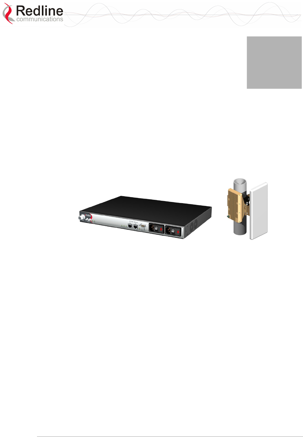
Figure 2: Intro - Base Station Terminal, Transceiver, and Antenna
The base station consists of an indoor terminal (IDU) and outdoor modem and antenna
(ODU). Each operational RedMAX wireless broadband network segment is comprised of
a RedMAX base station and one or more WiMAX Forum Certified subscribers. Each
subscriber registers and establishes a bi-directional data link with the base station sector
controller.
The RedMAX base station is (part of) the 802.16 definition of a base station. A RedMAX
base station functions as a central hub or concentrator, connected to a WAN network
access point, and managing wireless links for remote subscribers. The RedMAX base
station enforces the Quality of Service (QoS) settings by controlling all uplink and
downlink traffic scheduling -- providing non-contention based traffic with predictable
transmission characteristics.
2.2 IEEE 802.16 / WiMAX Compliance
The IEEE 802.16-2004 specifications describe a PMP broadband wireless access
standard for systems operating in the frequency range of 2-11 GHz, and 10-66 GHz. This
standard includes descriptions for both the Media Access Control (MAC) and the
physical (PHY) layers.
The RedMAX base station is compliant to the following IEEE 802.16-2004
WirelessMAN-OFDM and WirelessHUMAN-OFDM Physical Layer Profiles:

RedMAX™
Base Station
User Manual
Doc. #70-00058-01-01 Proprietary Redline Communications © 2007 July 13, 2007
Page 19 of 117
- ProfP3_3.5: WirelessMAN-OFDM PHY profile for 3.5 MHz channelization (Rel. 1.0)
- ProfP3_7: WirelessMAN-OFDM PHY profile for 7 MHz channelization (Rel. 1.1)
Note that the 802.16 standards are subject to amendment, and RedMAX product design
compliance applies to a specific revision of the standard. The RedMAX product does not
support mesh communication (direct subscriber-to-subscriber).
Redline is an active member of the IEEE 802.16 standards committee and has been
instrumental in creating the original 802.16 standards. Redline is also active in
recommending, writing and following-up on new amendments to the 802.16
specifications.
Redline is an active member of the WiMAX Forum™ and is participating in
interoperability testing in the WiMAX Forum.
2.3 PHY Specification
The base station is designed for 2-11 GHz operation based on the WirelessMAN-OFDM
PHY definition in the IEEE 802.16 specification. Refer to the system specifications for
supported frequency ranges.
2.4 OFDM (256 FFT)
The base station uses Orthogonal Frequency Division Multiplexing (OFDM). OFDM is a
multi-carrier transmission technique where the data stream is split and transmitted (at a
reduced rate) in parallel streams on separate sub-carriers. OFDM uses the Fast Fourier
Transform (FFT) algorithm to implement modulation and demodulation functions. Using
adequate channel coding and bit-interleaving, OFDM can perform very well in severe
multipath environments, mitigate frequency selective fading and provide high spectral
efficiency.
2.5 Features
2.5.1 Privacy
The base station is hardware ready to provide encryption for user traffic. The MAC
header of 802.16 contains the information Encryption Control (EC), Encryption Key
sequence (EKS) , and Connection Identifier (CID) necessary to decrypt a payload by the
receiver. Protection of the payload is indicated by the EC bit field. A value of '1' indicates
the payload is cryptographically protected and the EKS field contains meaningful data. A
value of '0' indicates the payload is not cryptographically protected. The EKS field
contains a sequence number used to identify the current generation of keying material.
2.5.2 Time Division Duplexing (TDD)
The base station system uses time division duplexing (TDD) to transmit and receive on
the same RF channel, or using separate RF channels using half-duplex FDD (HD-FDD).
These are both non-contention based methods for providing an efficient and predictable
two-way PTP or PMP cell deployment. All uplink and downlink transmission scheduling
is managed by the base station. The base station sends data traffic to subscribers, polls for
grant requests, and sends grant acknowledgements based on the total of all traffic to all
subscribers.
RedMAX™
Base Station
User Manual
Doc. #70-00058-01-01 Proprietary Redline Communications © 2007 July 13, 2007
Page 20 of 117
2.5.3 Coding Rate
Each burst of data transmitted over the wireless interface is padded with redundant
information, making it more resistant to potential over-the-air errors. The coding rate is
the ratio of user data to the total data transmitted including the redundant error correction
data. The base station supports coding rates of 1/2, 2/3, and 3/4.
2.5.4 Modulation
The modulation technique specifies how the data is coded within the OFDM carriers. The
base station supports BPSK, QPSK, 16 Quadarature Amplitude Modulation (QAM), and
64 QAM modulation.
2.5.5 Reed Solomon Error Correction
Outer Reed-Solomon and inward Convolution Coding (RS-CC) error correction is
enabled for all traffic rates, with the exception of BPSK 1/2 where only inward
Convolution Coding is used. These low-level processes can correct bursts of errors in
received messages and reduce the number of retransmissions.
2.5.6 Time Synchronization
When operating two or more collocated base stations, transmitter operations MUST be
synchronization to minimize inter-sector interference. Each base station has a
synchronization port located on the front panel to receive synchronization pulses.
2.6 Deployment Models
The base station supports point to point (PTP) and point to multipoint (PMP) deployment
scenarios.
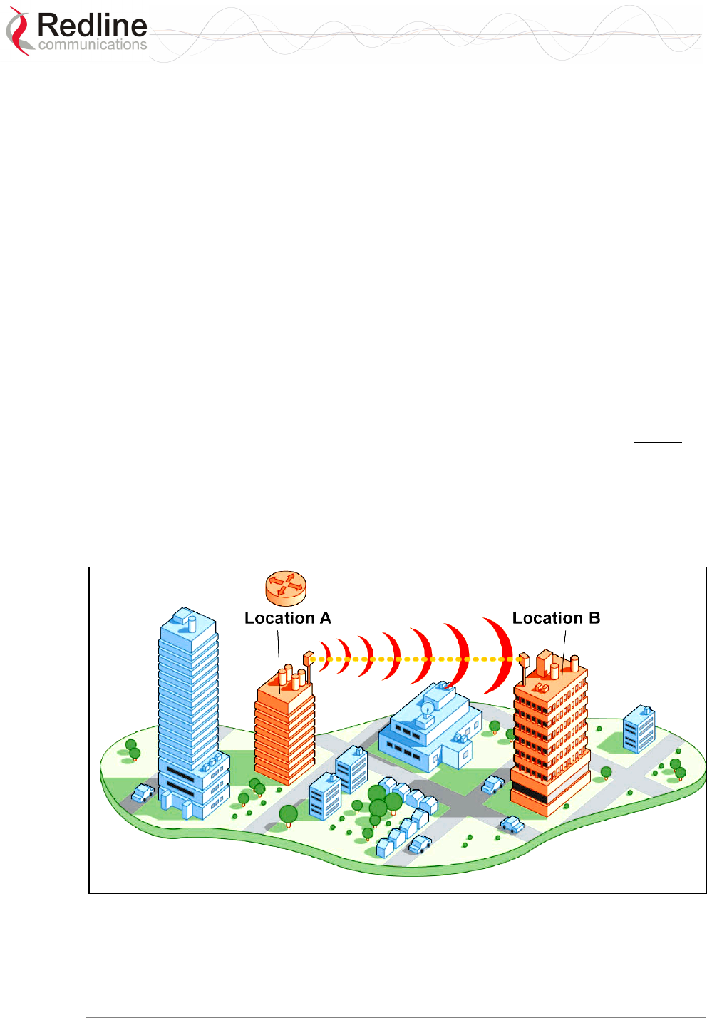
Figure 3: System - PTP Line of Sight Deployment
RedMAX™
Base Station
User Manual
Doc. #70-00058-01-01 Proprietary Redline Communications © 2007 July 13, 2007
Page 21 of 117
2.6.1 PTP Deployment
When deployed in a PTP configuration the base station establishes a dedicated bi-
directional link to a single subscriber. The PTP deployments typically use a directional
narrow beam antenna for both ends of the link.
2.6.2 PMP Deployment
When deployed in a PMP configuration the base station establishes bi-directional links to
more than one subscriber. PMP deployments typically use a wide beam (sector) antenna
at the base station and a narrow beam antenna at the subscriber. Service flows are used to
police service level agreements for each subscriber.
2.6.3 Non Line-of-Sight
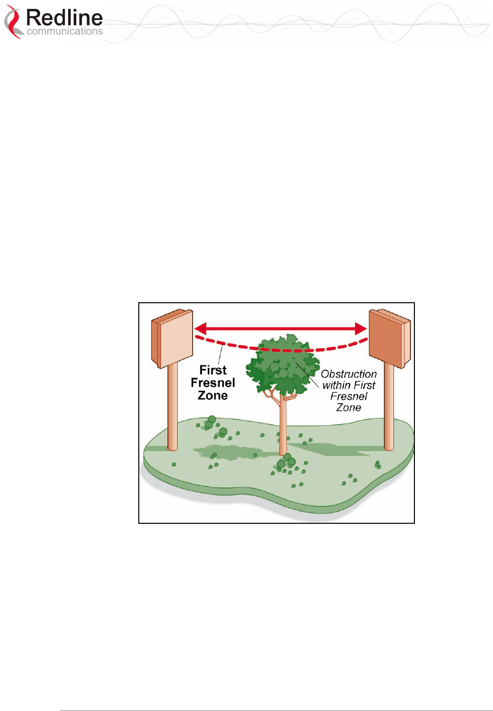
The RedMAX system supports line-of-sight (LOS), optical line-of-sight (OLOS), and
non line-of-sight (NLOS) operation. A clear LOS link has no obstacles within 60% of the
first Fresnel zone of the direct path. An OLOS link has obstructions within 60% of the
first Fresnel zone, but a visible path exists between the base station and subscriber. Refer
to the following illustration.
Figure 4: System - Fresnel Zone
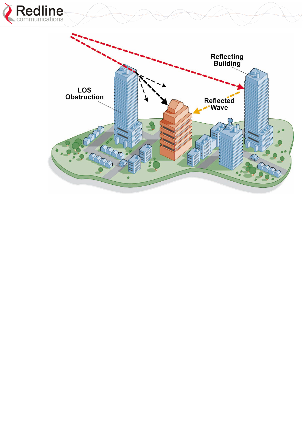
A wireless link is considered non LOS if natural or man-made structures block the visible
path between the base station and the subscriber. In this case, a wireless link can be
established only if a reflective path can be established between the base station and
subscriber.
RedMAX™
Base Station
User Manual
Doc. #70-00058-01-01 Proprietary Redline Communications © 2007 July 13, 2007
Page 22 of 117
Figure 5: System - Non-Line of Sight Deployment
2.6.4 Channelization
The base station is a frequency-specific system, with the frequency band defined by the
modem unit. The use of the operating band must be in accordance with European
Conference of Postal and Telecommunications Administrations (CEPT)
Recommendation 14-03.
The base station divides the available frequency band into channels. Allocation of
channels during deployment is dependent on spectrum availability in the licensed FWA
band and local licensing requirements and conditions. Channel selection allows planners
to obtain the maximum geographic coverage, while avoiding frequency contention in
adjacent sectors.
2.7 Service Flows
Service flows are a key feature of the 802.16 standard.
A service flow represents a unidirectional data flow. Transmitting bidirectional traffic
requires that two service flows be defined: one for the uplink, and another for the
downlink. These service flows can have different QoS settings.
The base station allows multiple service flows to be configured for each subscriber in a
sector. This allows service providers to offer different services, and segregate traffic
flows having different QoS requirements.
A service flow is partially characterized by the following attributes:
1. A 32-bit Service Flow ID (SFID) is assigned to all existing service flows. The SFID
serves as the principal identifier for the Service Flow and has an associated direction.
2. A 16-bit Connection ID (CID) is associated with each active SFID (connection
active).

RedMAX™
Base Station
User Manual
Doc. #70-00058-01-01 Proprietary Redline Communications © 2007 July 13, 2007
Page 23 of 117
3. A set of QoS parameters specifying the required resources. The principal resource is
bandwidth, but the specification may also include latency requirements.
4. A set of QoS parameters defining the level of service being provided.
2.7.1 Service Flow Classification
Data packets are forwarded based on classification rules. Classification rules require
examining each packet for pattern matches such as destination address, source address, or
VLAN tag. All classification is defined at the base station and the classification
parameters are downloaded to the subscriber.
2.7.2 Dynamic Service Addition
Service flows are defined and stored in the base station. For each service flow to be
established, the base station sends a setup message to the subscriber specifying the
required set of QoS parameters. The subscriber responds to each request by accepting or
rejecting the setup message.
A service flow may be pre-provisioned or can be dynamically created and deleted
without service outage. This is useful for supporting multiple subscribers in a single
sector. New subscribers can be added and existing subscribers can be removed or have
service levels modified.
Setup messages are sent by the base station following any subscriber power-cycle, loss
and recovery of the wireless link to a subscriber, or any service flow add/delete operation
at the base station.
2.7.3 Default Service Flows
Default UL/DL service flows are created automatically for each registered subscriber.
These service flows are used to pass all traffic not matching any user-defined service
flow (such as broadcast ARP) between the base station and subscribers. The default
service flow capacity is limited for each subscriber.
2.7.4 Scheduling
The base station enforces QoS settings for each service flow by controlling all uplink and
downlink traffic scheduling. This provides non-contention based traffic model with
predictable transmission characteristics. By analyzing the total of requests of all
subscribers, the base station ensures that uplink and downlink traffic conforms with the
current service level agreements (SLAs). Centralized scheduling increases predictability
of traffic, eliminates contention, and provides the maximum opportunity for reducing
overhead.
A regular period is scheduled for subscribers to register with the base station. These
subscribers may be newly commissioned or have been deregistered due to service outage
or interference on the wireless interface. This is the only opportunity for multiple
subscribers to transmit simultaneously.
Real-Time Polling Service (rt-PS)
The base station schedules a continuous regular series of transmit opportunities for the
subscriber to send variable size data packets. The grant size is based on the current data
transfer requirement. Typical applications include streaming MPEG video or VOIP with

RedMAX™
Base Station
User Manual
Doc. #70-00058-01-01 Proprietary Redline Communications © 2007 July 13, 2007
Page 24 of 117
silence suppression. This is efficient for applications that have a real-time component and
continuously changing bandwidth requirements.
Non-Real-Time Polling Service (nrt-PS)
The base station schedules regular transmit opportunities for the subscriber to send
variable size data packets. Typical applications may include high bandwidth FTP. The
polling period may typically be one second or less, even during periods of network
congestion.
Best Effort (BE)
The base station schedules transmit opportunities for the subscriber to send traffic based
on unused bandwidth after all higher level traffic scheduling requirements are serviced.
Typical applications may include Internet access and email. Best effort service flows can
be assigned a priority of 0 to 7.
Unsolicited Grant Service (UGS)
The base station schedules a continuous series of transmit opportunities for the subscriber
to send fixed size data packets. This schedule supports real-time applications including
VoIP or TDM transport. The UGS pre-scheduled grants guarantee reserved bandwidth
and reduce latency introduced by repetitive grant requests. The service flow will not
transmit packets larger than nominal grant interval.
Traffic Scheduling Algorithm
The base station scheduling algorithm uses two scheduling passes. On the first pass, the
scheduler attempts to allocate bandwidth to meet the minimum rates for all active service
flows. If there is available bandwidth remaining at the end of the first pass, the scheduler
executes a second pass and attempts meet all specified maximum rates. During both
passes, bandwidth allocations are assigned based on the following order of assessment:
1. Priority of the scheduling service type, from highest to lowest (rtPS first, and then
BE).
2. Traffic Priority setting when multiple service flows have the same service type.
Wireless transmission bandwidth is optimized by granting allocations based only on
traffic available for immediate transmission: only the required bandwidth is allocated,
and idle service flow channels do not receive any bandwidth allocation.
RedMAX™
Base Station
User Manual
Doc. #70-00058-01-01 Proprietary Redline Communications © 2007 July 13, 2007
Page 25 of 117
Chapter
3
3
3
P
Ph
hy
ys
si
ic
ca
al
l
D
De
es
sc
cr
ri
ip
pt
ti
io
on
n
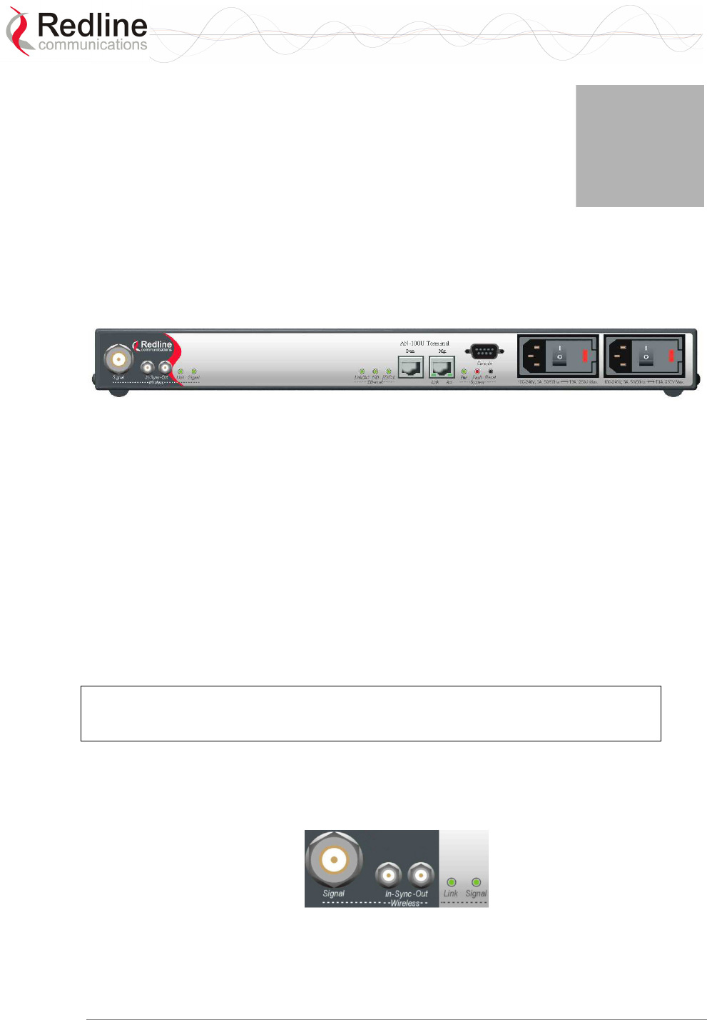
3.1 Base Station Terminal (IDU)
This section describes the characteristics of the base station terminal.
Figure 6: System - Front Panel
All indicator LEDs, power receptacles, data ports, and the reset switch are located on the
front panel of the terminal. There is a ground terminal provided at the rear of the
terminal.
3.1.1 Mounting
The terminal can be freestanding on a flat surface, or mounted into a standard 19-inch
equipment rack.
3.1.2 Power Supply
Power supply options include single or dual AC or DC supplies, or a combination of AC
and DC power supplies. Cables are included with both AC and DC power supplies. Refer
to section 8.6: DC Power Connections on page 109 for additional information about DC
power wiring.
Warning to service personnel:
Caution for all AC and DC models – Double Pole/Neutral fusing.
3.1.3 Wireless Section
This section describes the wireless port, base station time synchronization ports, and
wireless LEDs.
Figure 7: System - Front Panel Wireless Section
RedMAX™
Base Station
User Manual
Doc. #70-00058-01-01 Proprietary Redline Communications © 2007 July 13, 2007
Page 26 of 117
IF Port (Radio Control)
The terminal has a female N-type port for connection to the modem using a coaxial cable.
This port provides the following functions:
- Local oscillator signal for synchronization between the terminal and radio
- Telemetry signals for control and monitoring the modem
- IF modulated data to/from the radio (wireless interface)
- 24 VDC power to power the radio
Time Synchronization Port
The synchronization interface has two SMA female connectors located on the front panel.
Refer to section 8.6: DC Power Connections on page 109 for additional information.
Wireless LEDs
Link LED
The wireless Link LED flashes once every 8 frames to provide a 'heartbeat' indicator.
This indicates proper communication with the outdoor unit (ODU), and that the framer is
operating correctly. If this LED is not flashing, there is no possibility of establishing a
wireless link.
Table 4: System - Wireless Link LED Indications
LED State Description
FLASH Wireless interface enabled and functioning correctly.
OFF Wireless interface unavailable.
Signal LED
The Signal LED flashes each time a message is received from any subscriber. Message
types include: periodic ranging messages, bandwidth requests, and user data traffic.
Table 5: System - Wireless Signal LED Indications
LED State Description
ON Messages being received from subscribers.
OFF No wireless link activity.
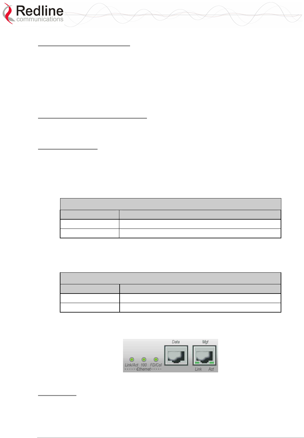
3.1.4 Ethernet Section
This section describes the Ethernet LEDs and port connections.
Figure 8: System - Front Panel Ethernet LEDs and RJ-45 Ports
Data Port
The Data port is always enabled. The port can be programmed to operate in full duplex or
half duplex mode and at 10 Mbps or 100 Mbps.
RedMAX™
Base Station
User Manual
Doc. #70-00058-01-01 Proprietary Redline Communications © 2007 July 13, 2007
Page 27 of 117
Data Port LEDs
Data Port Link/Act LED
The Link/Act LED lights green when the LAN connection to the host is functioning
properly.
Table 6: System - Ethernet Data Port Link/Act LEDs
LED Description
ON Link is present.
FLASH Link is present and there is data activity.
OFF Link is not active.
Data Port 100 LED
The 100 LED lights solid green when the terminal is operating at 100 Mbps. The LED is
off when operating at 10 Mbps.
Table 7: System - Ethernet Data Port 100 LEDs
LED Description
ON LAN is operating at 100 Mbps.
OFF LAN is operating at 10 Mbps.
Data Port FD/Col LED
The FD/Col LED lights green when the port is operating in Full Duplex mode. The LED
flashes when collisions are detected.
Table 8: System - Ethernet Data Port FD/Col LEDs
LED Description
ON Full duplex operation
FLASH Packet collisions detected on the LAN
OFF Half Duplex operation
Note: There are always collisions occurring on a Half-Duplex link.
Mgt Port
The Mgt port is used for out-of-band management and diagnostics. This port can be
disabled and management traffic sent through the data port.
Mgt Port LEDs
Mgt Port Link (Link/Act) LED
The Mgt port Link LED lights green when a link is established.
Table 9: System - Ethernet Mgt Port Link LEDs
LED Description
ON Ethernet interface is present.
FLASH Ethernet interface is present and there is data activity.
OFF Ethernet interface is not active.
RedMAX™
Base Station
User Manual
Doc. #70-00058-01-01 Proprietary Redline Communications © 2007 July 13, 2007
Page 28 of 117
Mgt Port Act (100) LED
The 100 LED lights solid green when the Mgt port is operating at 100 Mbps. The LED is
off when operating at 10 Mbps.
Table 10: System - Ethernet Mgt Port Act LEDs
LED Description
ON Ethernet interface is operating at 100 Mbps.
OFF Ethernet interface is operating at 10 Mbps.
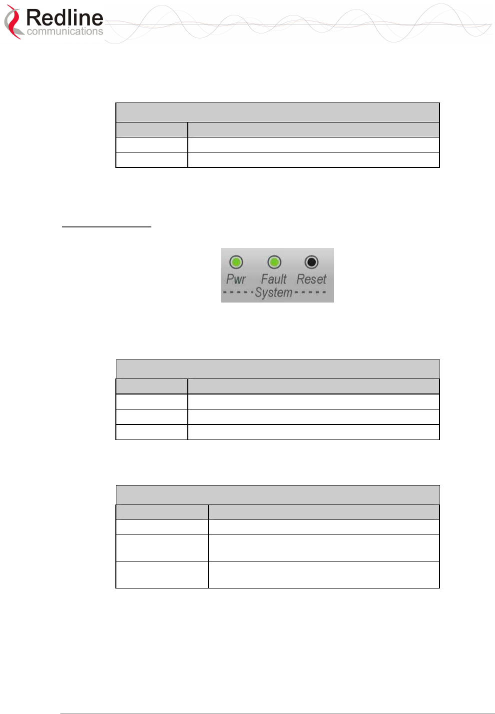
3.1.5 System Section
This section describes other general features of the front panel.
System LEDs
The System LEDs indicate power supply status and system faults.
Figure 9: System - System LEDs and Reset Switch
System Pwr LED
The Pwr LED lights green to indicate normal operation.
Table 11: System - Pwr LED Indications
LED Description
ON Normal operation.
FLASH One of the dual AC/DC power supplies is off.
OFF System is turned off.
System Fault LED
The Fault LED lights red when a serious fault is detected.
Table 12: System - Fault LED Indications
LED Description
OFF Normal operation.
FLASH Only one of the dual power supplies is
operational.
ON Serious problem with the system hardware. Refer
to the Troubleshooting section.
RedMAX™
Base Station
User Manual
Doc. #70-00058-01-01 Proprietary Redline Communications © 2007 July 13, 2007
Page 29 of 117
Reset Switch
The Reset button is recessed in the front panel of the terminal. To operate the switch,
use a small narrow object (i.e., paper clip) to depress the switch.
Table 13: System - Front Panel Reset Switch
Operation Result
Depress switch
less than 5
seconds
Short-reset. A short-reset is equivalent to cycling the
terminal power off/on. Statistics counters are reset.
Depress switch
longer than 5
seconds
Long-reset. A long-reset sets the IP address and
password to the factory defaults. Refer to Troubleshooting
section.
3.1.6 Grounding Connection
A ground terminal is located on the rear of the terminal. Correct grounding is very
important for safe operation of wireless equipment.
3.1.7 Console Port
The console port requires a crossover (null modem) cable to connect directly to a PC
serial port emulating a VT-52 or VT-100 terminal. The following table lists the default
settings for the Console port:
Table 14: System - Console Port Default Settings
Baud 57,600
Data Bits 8
Flow Control None
Parity None
Stop Bits 1
The following table lists the Console port pinout and associated signals.
Table 15: System - Console Port (RS-232) Pinout
Pin Name RS232 V.24 Description
2 RXD BB 104 Receive Data
3 TXD BA 103 Transmit Data
5 GND AB 102 System Ground
Note: V.24 column is ITU-TSS V.24 circuit name.
RedMAX™
Base Station
User Manual
Doc. #70-00058-01-01 Proprietary Redline Communications © 2007 July 13, 2007
Page 30 of 117
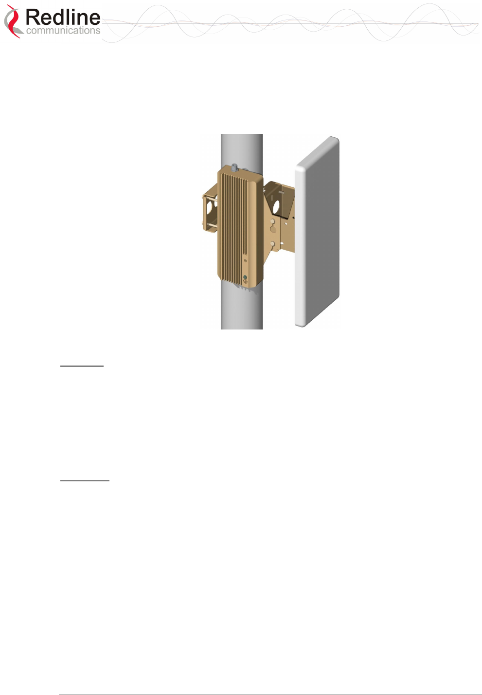
3.2 Radio (ODU)
3.2.1 Transceiver
The radio modem is housed in a weatherproof aluminum alloy case. The modem features
are listed in the following sections.
Figure 10: System - Transceiver and Antenna
IF Port
The modem has a female N-type port for connection to the terminal using a coaxial cable.
Through this port and cable, the modem:
- Sends/receives IF modulated data to/from the terminal.
- Transmits status information to the terminal.
- Receives control information from the terminal.
- Receives DC power from the terminal.
RF Port
The modem RF port (female N-type connector) is used for sending/receiving the RF
signal to/from the antenna. A short coaxial cable is provided to connect the modem to the
antenna.
3.2.2 Antenna
The antenna RF port (female N-type connector) is for sending/receiving the RF signal
to/from the modem. A short coaxial cable is provided to connect the antenna to the
modem.
3.2.3 Antenna Mounting Bracket
A vertical-mount bracket is provided with the system. The vertical mount bracket can
accommodate 4.45 - 11.45 cm (1 ¾ - 4 ½") OD masts found on many commercial tower
installations.
RedMAX™
Base Station
User Manual
Doc. #70-00058-01-01 Proprietary Redline Communications © 2007 July 13, 2007
Page 31 of 117
Chapter
4
4
4
W
We
eb
b
I
In
nt
te
er
rf
fa
ac
ce
e
All configuration and monitoring functions can be performed using the web-based
interface described in detail in this chapter.
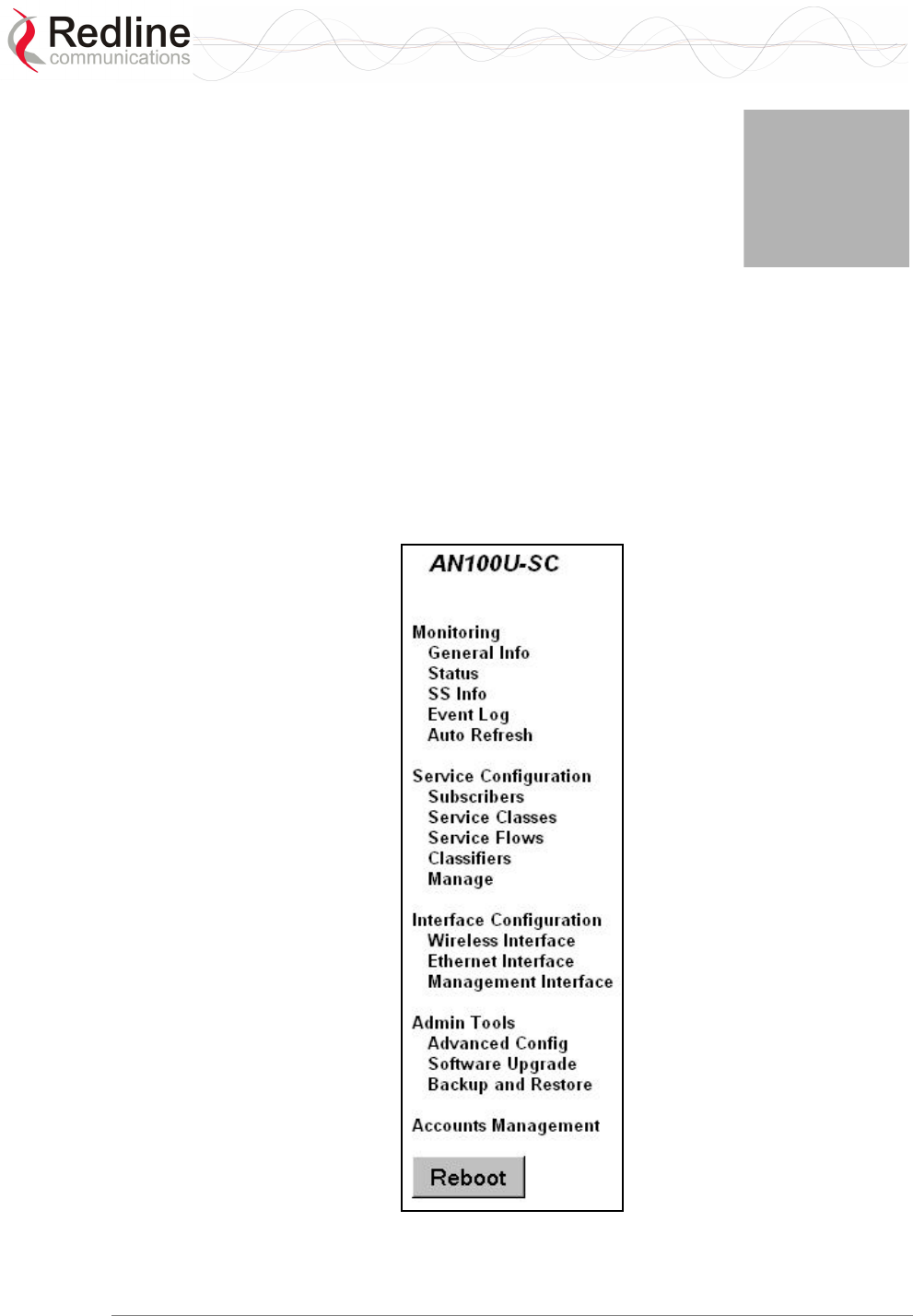
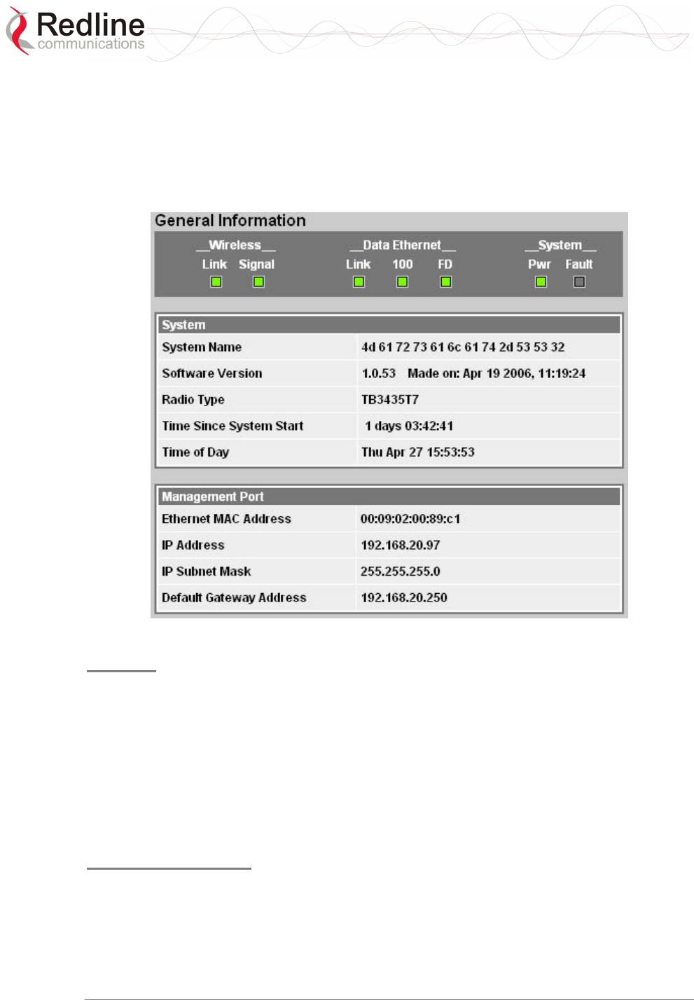
4.1 System Menu
When you login to the base station the General Information page is displayed. A menu
of all available monitoring and configuration screens is located at the left side of the
screen. Point and click any of the menu items in the menu to display the selected screen.
Figure 11: Web: Base Station System Menu

RedMAX™
Base Station
User Manual
Doc. #70-00058-01-01 Proprietary Redline Communications © 2007 July 13, 2007
Page 32 of 117
The debug user has unrestricted access to all screens and controls. All other users have
restricted access. See the following table for details.
Table 16: Web: Base Station Screens and Access Control
Function Screen
Title
Guest
Access
Admin
Access
Debug
Access
Description
Monitoring General Info X X X View general system
information, Ethernet settings,
and wireless settings.
Status X X X View statistics for the wireless
interface, Ethernet data port,
and management port.
SS Info X X X View system information,
Ethernet settings, and wireless
statistics for active subscribers.
Event Log X X X View system activity and error
messages.
Auto Refresh x x x Select the rate to automatically
refresh the web screen.
Service Flow
Configuration.
Subscribers X X Summary of registered
subscribers.
Service
Classes
X X Define the set of service
classes.
Service Flows X X Define service flows based on
the service classes.
Classifiers X X Define classifiers for each
service flow.
Manage X X Activate service flows.
Interfaces
Wireless
Interface
X X View and modify RF, PHY, and
MAC settings for the wireless
interface.
Ethernet
Interface
X X View and modify the Ethernet
network interface settings.
Management
Interface
X X View and modify the IP and
DHCP network interface
settings.
Admin Tools Advanced
Config
X View and modify advanced
wireless interface settings.
Software
Upgrade
X X Upload new system software
and select the software version
to load at startup.
Backup and
Restore
X X Backup and restore
configuration settings using
remote FTP server.
Accounts
Management
X X X Add users and change system
passwords.
Reboot X X Reset the base station
terminal.
RedMAX™
Base Station
User Manual
Doc. #70-00058-01-01 Proprietary Redline Communications © 2007 July 13, 2007
Page 33 of 117
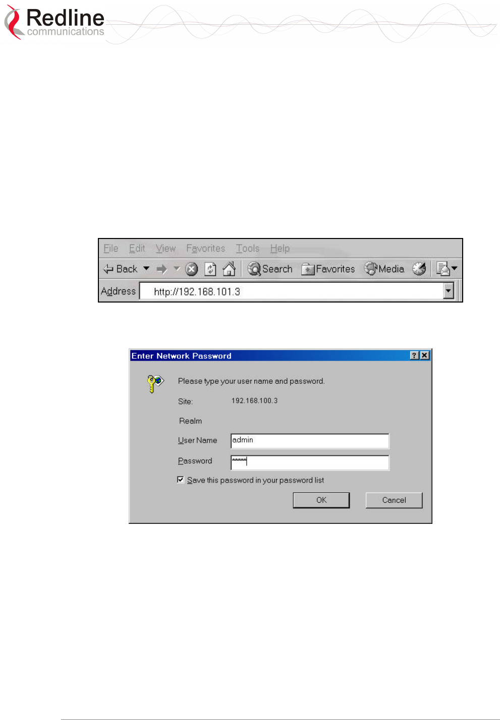
4.1.1 Configuration Using a Web Browser
1. Set the IP address of your PC to the following settings:
IP Address: 192.168.101.110
Subnet mask: 255.255.255.0
2. Connect the host (laptop) computer directly to the Data port of the base station
terminal using an RJ-45 Ethernet (straight-through) cable.
3. Power-on the base station terminal and restore the factory default settings by
depressing the reset switch on the front panel for more than five (5) seconds.
4. Launch a Web Browser on the PC and enter the terminal IP address in the browser
address field (192.168.101.3). The General Information screen is displayed and the
operator can now login to the terminal.
Figure 12: Web: Access - Browser Address Field
Click on any configuration menu item to activate the login dialog screen.
Figure 13: Web: Access - Base Station Login Screen
Enter the default user name and password:
User Name: admin
Password: admin
RedMAX™
Base Station
User Manual
Doc. #70-00058-01-01 Proprietary Redline Communications © 2007 July 13, 2007
Page 34 of 117
4.2 Monitoring Screens
This section describes the screens displaying system information and statistics.
4.2.1 General Info
Click General Information in the system menu (left side of screen) to view general
information, management settings, and the system front panel LEDs.
Figure 14: Web: Monitoring - General Information Screen
System
System Name: Assigned name for this base station.
Software Version: Current version of software running on the base station.
Radio Type: Identifies the modem type connected to this base station. Refer to the
Appendices for a list of supported radio types and designations.
Time Since System Start: Time elapsed since the base station was last reset.
Time of Day: Current date and time. Requires SNTP network server interface to be
enabled. Refer to section 4.4.3: Management Interface on page 63.
Management Port
Ethernet MAC Address: Base Station MAC address.
IP Address: Base Station network IP address.
IP Subnet Mask: Base Station network IP subnet mask.
Default Gateway Address: IP address of the default network gateway.
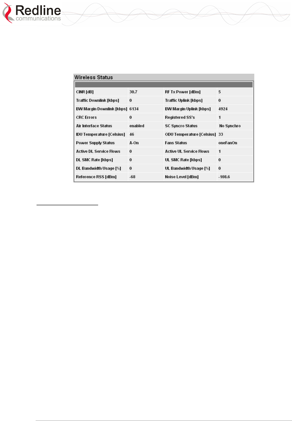
RedMAX™
Base Station
User Manual
Doc. #70-00058-01-01 Proprietary Redline Communications © 2007 July 13, 2007
Page 35 of 117
4.2.2 Status
Click Status in the system menu (left side of screen) to view status information about the
wireless interface and Ethernet management interface. Values are updated according to
the screen refresh rate.
Figure 15: Web: Monitoring - Status - Wireless Status Screen
Wireless Status
CINR [dB]: Mean Carrier/(Interference + Noise) ratio. The CINR value is calculated and
displayed for each automatic screen refresh. The CINR measured by the base station is
based on the signal from the subscriber. Based on this value, the base station may request
that the subscriber change modulation rate.
Traffic Downlink [kbps]: Rate of traffic transmitted to subscribers.
BW Margin Downlink [kbps]: Downlink bandwidth available that can be scheduled by
the base station (based on the minimum traffic rate settings for all active service flows).
CRC Errors: Number of CRC errors detected on packets received from subscribers. This
counter is reset when an base station is rebooted.
Note: The CRC Errors counter in the SS Info screen is reset when a subscriber is
registered.
Air Interface Status: Status of the base station modem:
Enabled - Transceiver is operating normally.
Disabled - Transceiver is disconnected, disabled, or defective.
IDU Temperature [Celsius]: Internal temperature of the indoor terminal.
Power Supply Status: Display the status of the power circuits.
A-On - Terminal is equipped with AC circuits only.
D-On - Terminal is equipped with DC circuits only.
A-D - Terminal is equipped with AC and DC circuits.
Active DL Service Flows: Number of currently active downlink service flows.
DL SMC Rate [kbps]: Data rate for downlink channel.

RedMAX™
Base Station
User Manual
Doc. #70-00058-01-01 Proprietary Redline Communications © 2007 July 13, 2007
Page 36 of 117
DL Bandwidth Usage [%]: Current usage of downlink channel.
Reference RSS [dBm]: The Reference RSS setting is the target value for average
Received Signal Strength (RSS) for subscribers RF signals received by the base station.
This target value allows automatic adjustment of the subscriber Tx power for optimum
performance with the minimum of RF interference. The suggested default setting for the
Reference RSS value is:
Channel Size Initial Setting
3.5 MHz -75 dBm
7.0 MHz -72 dBm
These are the suggested initial settings; adjustments to this target value must be made
based on the individual RF characteristics of each deployed sector. The RSSI value
(dBm) for each subscriber can be monitored using the base station SS Info screen (Web
interface). Tx power adjustments are based on a number of factors, and differences of up
to 7 dB may be observed between the Reference RSS setting and measured RSSI.
RF Tx Power [dBm]: Radio transmission output power level.
Traffic Uplink [kbps]: Rate of traffic received from subscribers.
BW Margin Uplink [kbps]: Uplink bandwidth available that can be scheduled by the
base station (based on the minimum traffic rate settings for all active service flows).
Registered SS's: Number of subscribers currently registered with the base station.
SC Synchro Status: Status of the base station time synchronization. Refer to the
RedMAX Base Station Installation Guidelines for complete details of the synchronization
feature.
No Synch - base station is not using synchronization.
Master with GPS Synchro - base station is Master and is synchronized to an
external GPS clock.
Master - base station is Master and is using internal clock.
Slave - base station is Slave.
Backup Slave - base station is Backup Slave and will assume Master operations if
Master is unavailable.
ODU Temperature [Celsius]: Internal temperature of the modem.
Fans Status: Display the status of the system cooling fans.
oneFanOn - A single cooling fan is operating.
twoFansOn - Both cooling fans are operating.
Active UL Service Flows: Number of currently active uplink service flows.
UL SMC Rate [kbps]: Data rate for uplink channel.
UL Bandwidth Usage [%]: Current usage of uplink channel.
Noise Level [dBm]: Indicates the noise level. This value is measured by sampling the
radio receiver input during idle periods (base station and subscribers are not transmitting)
and provides an indication of the average level of interference in the sector.
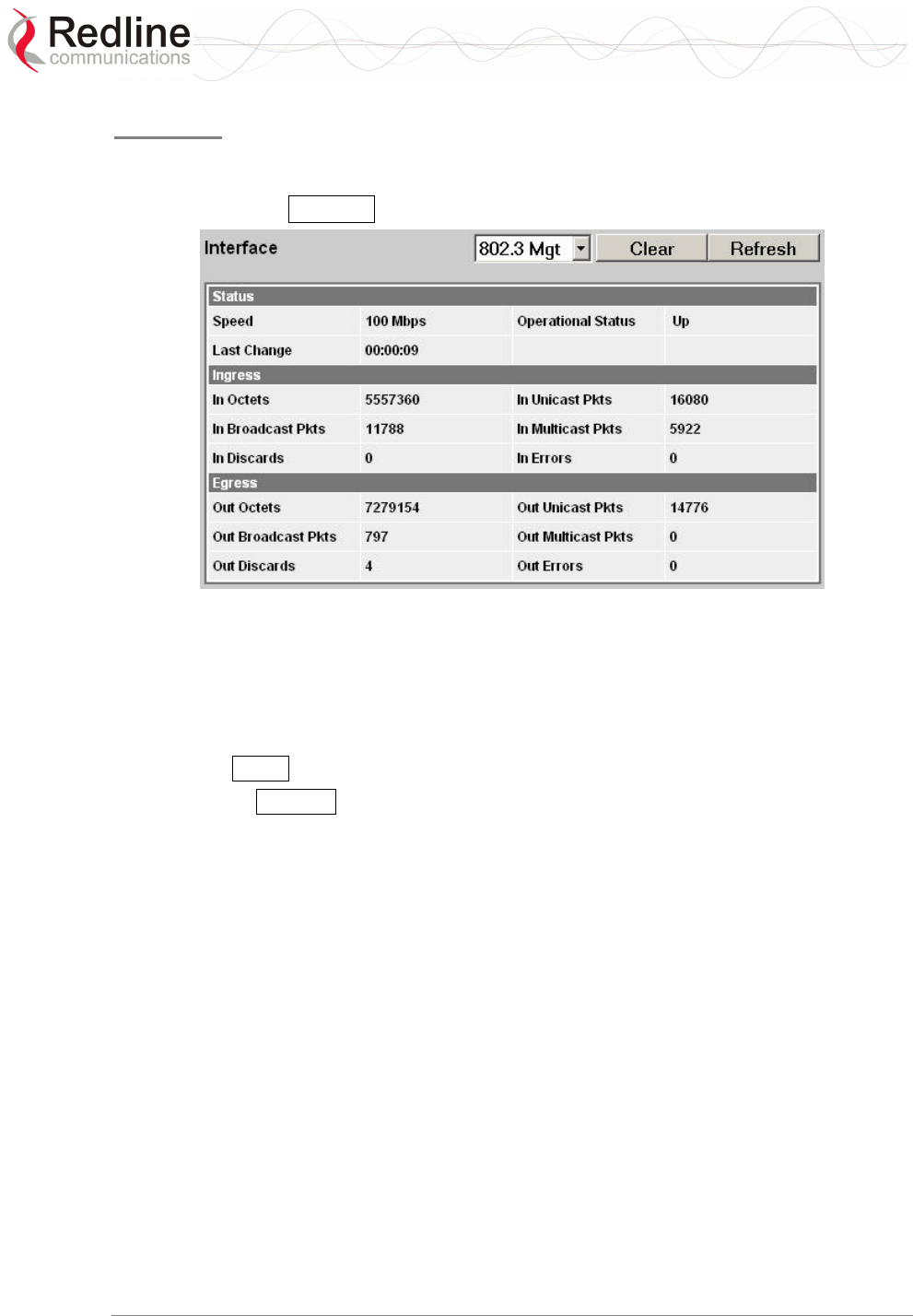
RedMAX™
Base Station
User Manual
Doc. #70-00058-01-01 Proprietary Redline Communications © 2007 July 13, 2007
Page 37 of 117
Interface
The interface panel provides statistics for the wireless interface (802.16), the data
Ethernet port Data), and the management (Mgmt) Ethernet port. Select the desired
interface and Click Refresh to update the screen.
Figure 16: Web: Monitoring - Status - Wireless Statistics Screen
Interface: Click the arrow in the menu box to select the desired interface:
802.16 - Wireless interface.
802.3 Data - Data Ethernet port.
802.3 Mgmt - Management Ethernet port.
Clear: Click Clear to reset the statistics on the selected interface.
Refresh: Click Refresh button after changing the selected interface type, or anytime to
display the latest statistics for the selected .
Status
Speed: Current speed of the interface.
Operational Status: Display the current status of the wireless interface.
Up - Operational link to at least one subscriber.
Down - No operational links to subscribers.
Last Change: Time of the last change in the operational status or the wireless link.
Ingress
In Octets: Total number of good octets received.
In Unicast Pkts: Total number of received valid Ethernet frames with a unicast
destination address.
In Not Unicast Pkts: Total number of received valid Ethernet frames with a multicast or
broadcast destination address.
In Discards: Total number of valid Ethernet frames that are discarded due to lack of
buffer space. This includes both frames discarded at ingress and frames discarded at
egress due to priority and congestion at the output queues.

RedMAX™
Base Station
User Manual
Doc. #70-00058-01-01 Proprietary Redline Communications © 2007 July 13, 2007
Page 38 of 117
In Errors: Total number of Ethernet frames that are discarded because of invalid Frame
Check Sequence (FSC).
Egress
Out Octets: Total number of good octets transmitted.
Out Unicast Pkts: Total number of frames transmitted with a unicast Destination
address.
Out Not Unicast Pkts: Total number of frames transmitted with a Multicast or Broadcast
Destination address.
Out Discards: Total number of valid Ethernet frames that are discarded due to lack of
buffer space. This counter is always 0 (all such discards are already counted in
InDiscards).
Out Errors: Total number of packets that were transmitted with an invalid FCS.

RedMAX™
Base Station
User Manual
Doc. #70-00058-01-01 Proprietary Redline Communications © 2007 July 13, 2007
Page 39 of 117
4.2.3 SS Info
Click SS Information in the menu (left side of screen) to view system information,
Ethernet address settings, and wireless statistics for active subscribers.
Figure 17: Web: Monitoring - SS Info Screen
SS Information
Name: User-assigned name for subscriber. Click on the subscriber name (blue text) to
view the service flows settings and statistics.
IP: Secondary management channel (SMC) IP address for this subscriber.
Mgm: Indicates if the subscriber can be managed over the wireless interface. Refer to the
subscriber user manual for additional information about enabling remote management.
yes: The subscriber supports remote management.
no: The subscriber can not be managed remotely.
DL Mod: Modulation/coding setting for downlink channel.
UL Mod: Modulation/coding setting for uplink channel.
Min CINR: Minimum average CINR since system reboot.
Max CINR: Maximum average CINR since system reboot.
Curr CINR: Current CINR value.
UL CRC: Total number of CRC errors detected in transmissions from this subscriber.
DL CRC: Total number of CRC errors reported in transmissions to this subscriber.
RSSI: Received signal strength indicator value measured based on the signal received
from this subscriber.
Tx Pow: Transmit power of this subscriber.
Dist: Calculated distance from base station to subscriber (kilometers).
Refresh: Click Refresh to update the screen with the latest values.
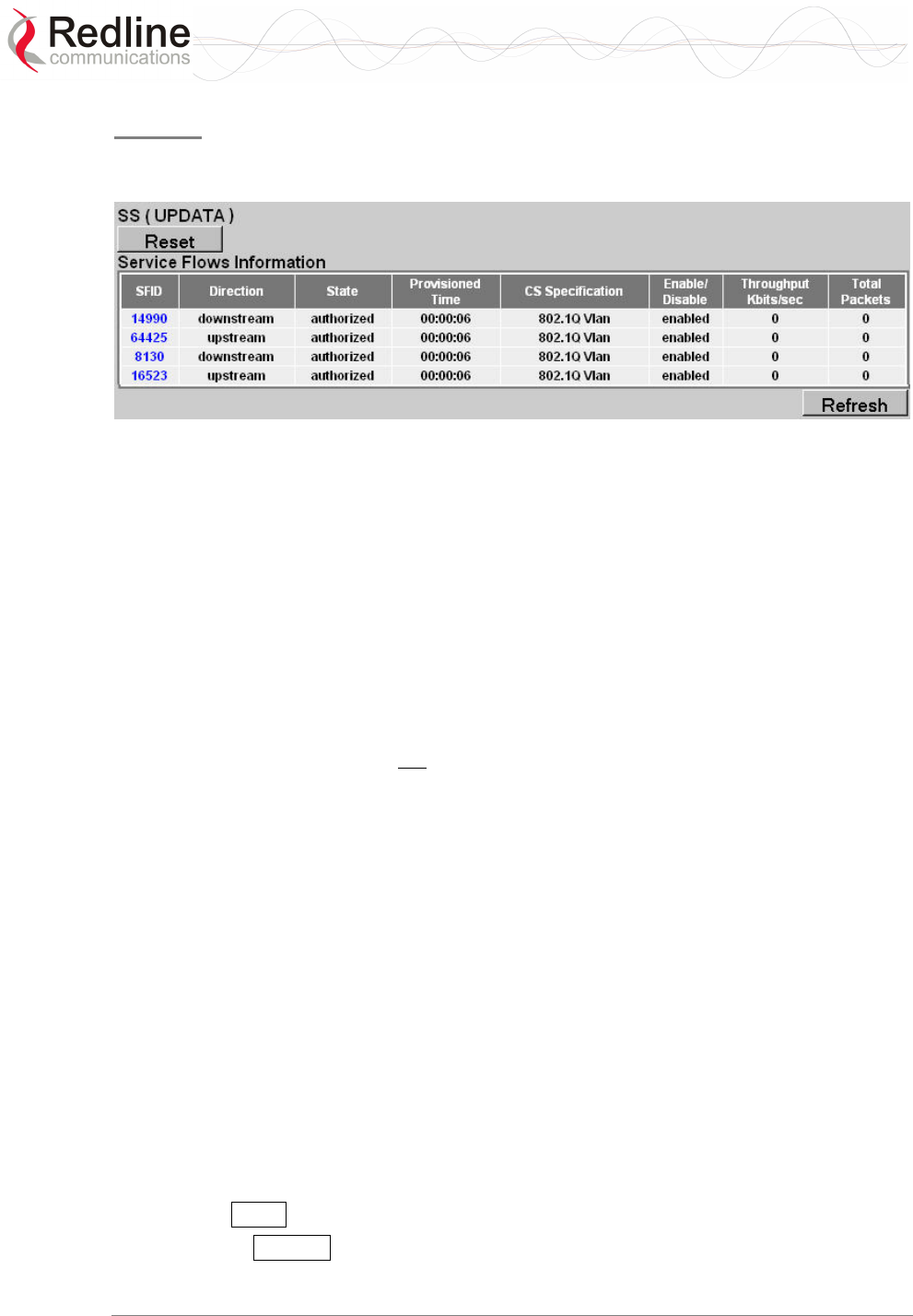
RedMAX™
Base Station
User Manual
Doc. #70-00058-01-01 Proprietary Redline Communications © 2007 July 13, 2007
Page 40 of 117
SF Info
Click the subscriber name listed in the SS Info screen to view service flow settings and
statistics.
Figure 18: Web: Monitoring - SS Info - SF Info Screen
SFID: Service flow identifier for this service flow.
Direction: Direction of service flow:
Downstream: Downlink traffic from base station to subscriber.
Upstream: Uplink traffic from subscriber to base station.
State: Current state of the service flow.
Active: Service flow is currently active.
Authorized: Service flow configuration has been saved but is not active.
Edited: Service flow configuration is being edited and is not saved.
Provisioned: Subscriber has been deregistered.
Rejected: Base Station was not able to setup the service flow.
Requesting: Base Station is attempting to setup the service flow.
Provisioned Time: Time elapsed since this service flow became active.
CS Specification: Classification type associated with this service flow.
802.3 Ethernet: The classifiers for this service flow are based on the combination of
the fields in the Ethernet packet's header.
IPv4: The classifiers for this service flow are based on the combination of the fields
in the packet's IP header.
802.1Q: The classifiers for this service flow are based on the combination of the
fields in the Ethernet packet's header and 802.1Q VLAN tag.
Enable/Disable: Indicate the operator selected status for this service flow:
Enabled: Service flow is manually enabled by the operator.
Disabled: Service flow is manually disabled by the operator.
Throughput Kbits/sec: Traffic throughput rate for this service flow.
Total Packets: Total packets exchanged with the subscriber (all service flows).
Reset: Click Reset to remotely reboot the selected subscriber.
Refresh: Click Refresh to update the screen with the latest totals.
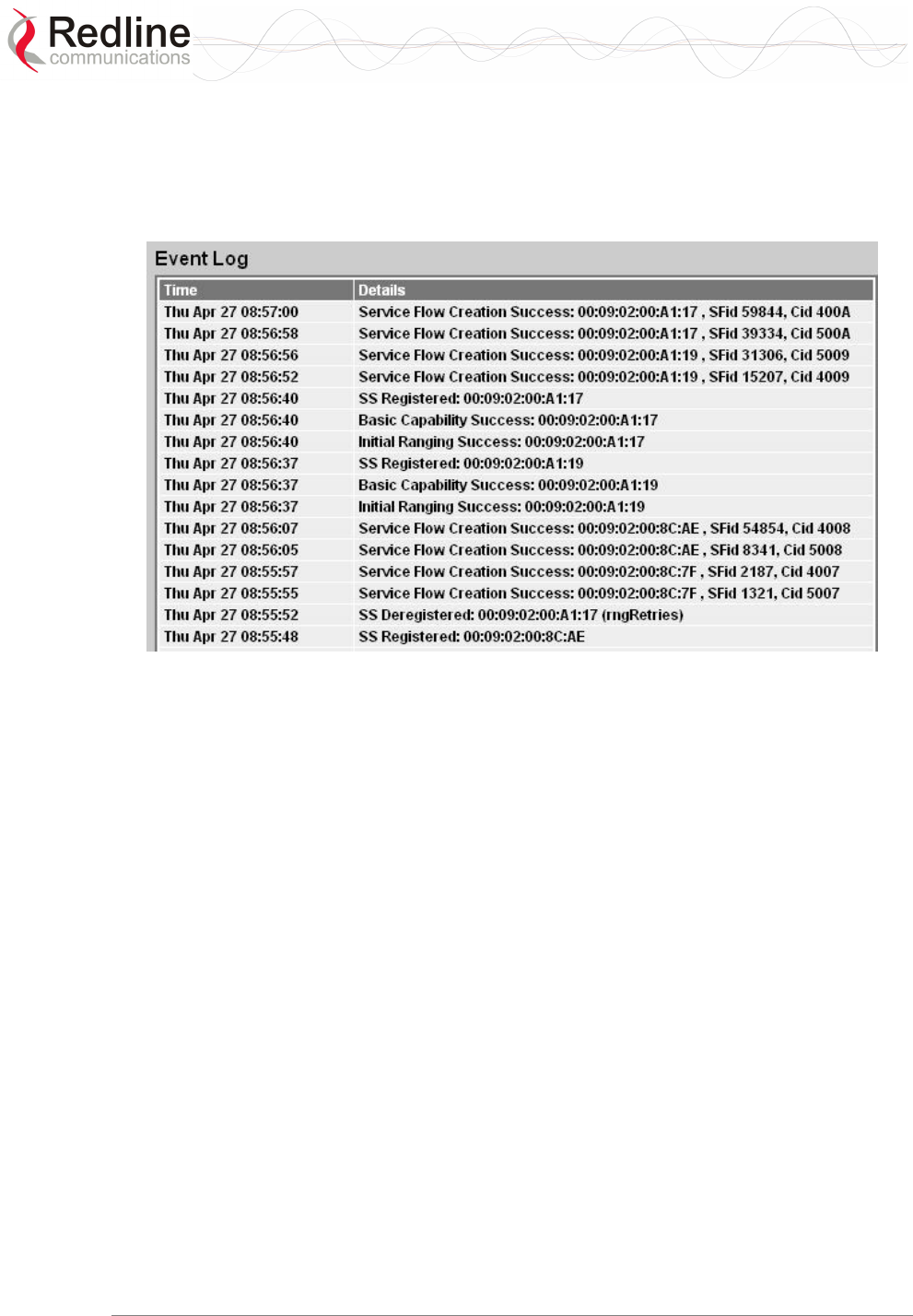
RedMAX™
Base Station
User Manual
Doc. #70-00058-01-01 Proprietary Redline Communications © 2007 July 13, 2007
Page 41 of 117
4.2.4 Event Log
Click Event Log in the menu (left side of screen) to view system activity and error
messages recorded by the terminal. Refer to section 0:
System Log Messages on page 100 for a list of system event messages.
Figure 19: Web: Monitoring - Event Log Screen
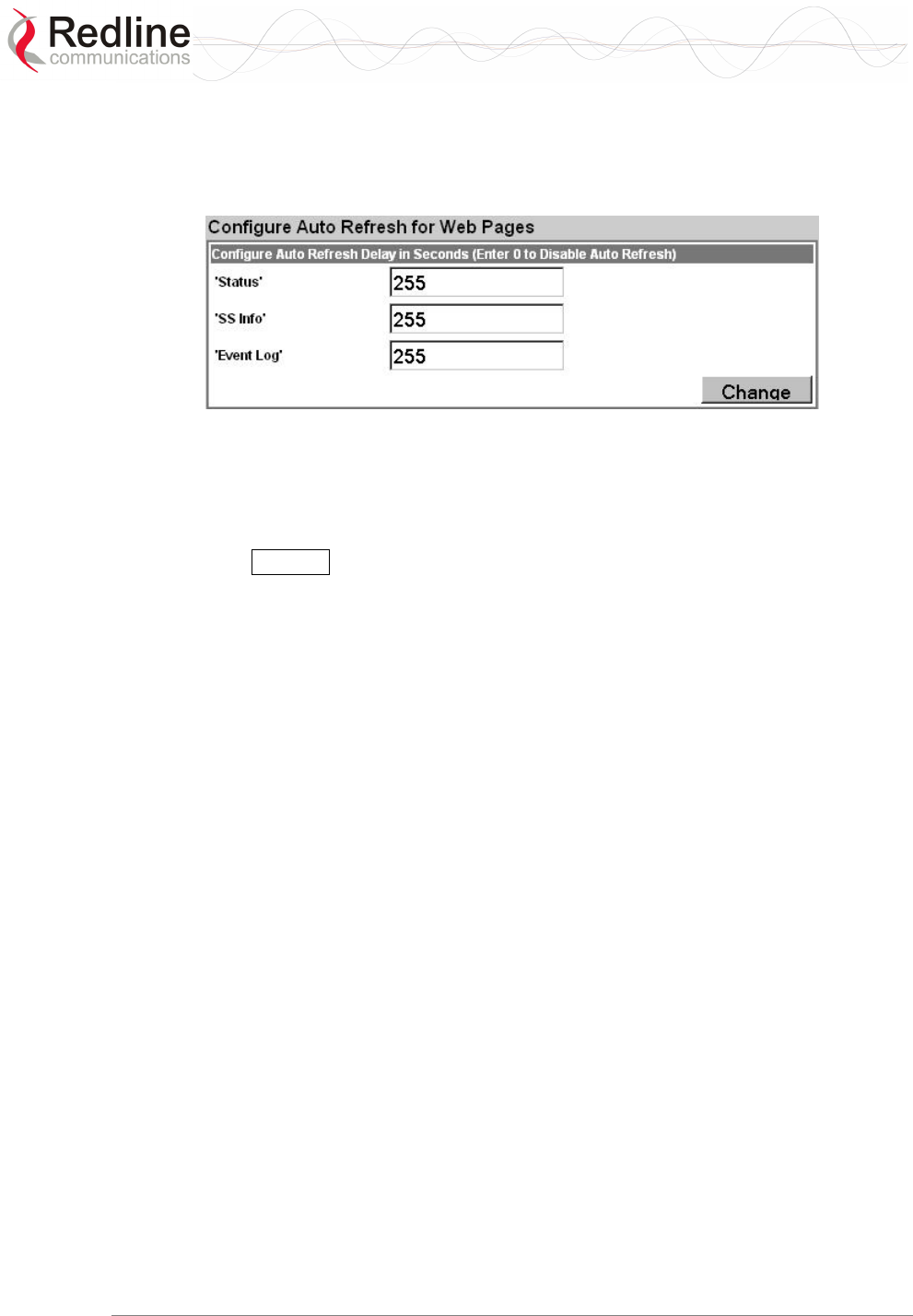
RedMAX™
Base Station
User Manual
Doc. #70-00058-01-01 Proprietary Redline Communications © 2007 July 13, 2007
Page 42 of 117
4.2.5 Auto Refresh
Click Auto Refresh in the menu (left side of screen) to view and modify the periods used
to automatically refresh the listed web screens.
Figure 20: Web: Monitoring - Auto Refresh Screen
Status: Set the automatic refresh period (seconds) for the Status screen.
SS Info: Set the automatic refresh period (seconds) for the SS Info screen.
Event Log: Set the automatic refresh period (seconds) for the Event Log screen.
Change: Click Change to update the screen with the latest totals.

RedMAX™
Base Station
User Manual
Doc. #70-00058-01-01 Proprietary Redline Communications © 2007 July 13, 2007
Page 43 of 117
4.3 Creating Service Flows - Overview
There are four steps associated with creating service flows:
Note: A service class can not be deleted until all provisioned/active service flows
referencing this service class have been deleted.
1. Create service class.
Each service class defines a set of QoS parameters that can be associated with a
service flow. Multiple service class definitions can be added to create a library of
service classes. By creating a set of standardized service classes, new service flows
can be added that conform to pre-defined service level agreements (SLAs). Each
service class definition includes traffic rates, latency settings, priority, and
transmission policy settings.
2. Create service flow.
All service flows are based on existing service class definitions. Separate service
flows are required for downlink and uplink traffic. Each definition requires
identifying the subscriber, flow direction, class of service, and the classifier type.
3. Define classifier.
A unique set of classifier rules can be defined for each service flow, depending on the
classification type (i.e., Packet, 802.3/Ethernet) selected when the service flow is
created. All associated classifiers are deleted when the service flow is deleted.
4. Activate
A new service flow is not activated until a classifier is assigned (click Add in the
Classifier screen).
If the target subscriber is registered a Dynamic Addition Session (DSA) session is
initiated. During a DSA session, the service flow is in Requesting state. If the DSA
session is successful, the state is set to Active. If the DSA session is not successful, the
state is set to Rejected.
If the target subscriber is not registered, the service flow request is stored until the
associated subscriber is registered. The subscriber registration triggers the activation
of all associated service flows.
RedMAX™
Base Station
User Manual
Doc. #70-00058-01-01 Proprietary Redline Communications © 2007 July 13, 2007
Page 44 of 117
4.3.1 Subscribers
Click Subscribers in the menu (left side of screen) to view a summary of the subscribers
currently configured on the base station.
Figure 21: Configuration - Service Class Screen
Subscriber Index: Unique index number to identify this subscriber. This number is
generated automatically by the base station. The user can also specify an index number
(must be unique) when creating a new subscriber entry.
Subscriber MAC: MAC address of the subscriber. You must enter this information
when creating a new subscriber entry.
Subscriber Name: Enter the name for this subscriber. This reference is displayed when
managing service flows and classifiers.
Note: When upgrading from RedMAX v1.0 this field will automatically be populated with
the subscriber MAC address. The name is not imported from the subscriber (set using
SNMP or CLI).
Max Hosts Number: Enter the maximum number of MAC addresses to discover on the
Ethernet interface to this subscriber. Valid only if Learning Enabled=Yes.
Learning Enabled: The MAC learning feature allows the base station to automatically
learn the MAC addresses of up to sixteen hosts (devices) on the Ethernet segment
connected to a subscriber. The learning feature can be enabled individually for any
subscriber.
Yes: Auto-learning is enabled for this subscriber.
No: Auto-learning is disabled for this subscriber.
Only (up to) the first sixteen learned hosts are recorded. The subscriber and base station
do not use 'MAC aging' and each learned host address will remain in the learning table
until the subscriber is rebooted. Reboot the subscriber to clear the MAC address table and
discover the current active hosts.
Add: Click Add to create a new subscriber listing. This button is active only when a new
MAC address has been specified in the Subscriber MAC field. When adding new

RedMAX™
Base Station
User Manual
Doc. #70-00058-01-01 Proprietary Redline Communications © 2007 July 13, 2007
Page 45 of 117
subscribers, the MAC learning feature is enabled by default and the host number is set to
one (1).
Delete SS
Subscriber: Select the name of the subscriber to be deleted.
Delete: Click Delete to deactivate and remove all classifiers and service flows for this
subscriber. The subscriber will be removed from the subscribers list.
Subscribers
Select: Use this field to select the name of the subscriber to be viewed, edited, or used as
a template for creating a new subscriber entry.
Template: Select a subscriber and click Template to display the current settings in the
upper portion of the screen. These settings can be modified and used to create a new
subscriber entry. Click Add to create the new subscriber entry.
Edit: Select a subscriber and click Edit to display the current settings the upper portion
of the screen. These settings for this subscriber can now be modified. Click Modify .to
save changes to this subscriber entry. You can not modify the index number for a
subscriber.
Important: Modifying an existing subscriber will cause the base station to delete and
recreate all service flows and classifiers for this subscriber.
RedMAX™
Base Station
User Manual
Doc. #70-00058-01-01 Proprietary Redline Communications © 2007 July 13, 2007
Page 46 of 117
4.3.2 Service Classes
Click Service Classes in the menu (left side of screen) to view, add, or delete service
class definitions. The base station will guarantee the QoS parameters for service flows
created referencing this service class.
Multiple service class definitions can be created to build a library of service classes. A
service class can not be deleted until all provisioned/active service flows referencing this
service class are deleted.
Figure 22: Configuration - Service Class Screen
Service Class Configuration Screen
Add a Service Class
Service Class Name: Enter a name for this service class. The name can be any
combination of up to 30 letters and numbers.
Traffic Priority: Enter the priority to be used for service flows created using this service
class. The priority is relative only to other service flows on the same subscriber. The
value '7' represents the highest priority.
Note: This is not the Ethernet (802.1p) priority setting.

RedMAX™
Base Station
User Manual
Doc. #70-00058-01-01 Proprietary Redline Communications © 2007 July 13, 2007
Page 47 of 117
Max. Sustained Rate (bps): Enter the maximum sustained wireless reserved rate. A
service flow created using this service class is limited to sustained transmission at this
rate (peak may be higher).
Min. Reserved Rate (bps): Enter the minimum wireless reserved traffic rate. T A service
flow created using this service class is guaranteed sufficient bandwidth for this rate.
Max Latency (ms): Enter the maximum latency allowed when forwarding packets from
the Ethernet port to the wireless interface. A service flow created using this service class
is guaranteed to have latency of less than or equal to this setting.
Fixed Vs. Variable Sdu Ind: Specify if all Ethernet packets are padded to the same
length.
fixedLength: All Ethernet packets is the same length.
variableLength: Ethernet packets is variable lengths.
Sdu Size: Enter the size for Ethernet packets. Enabled only if fixedLength is selected in
Fixed vs. Variable Sdu Ind field.
Scheduling Type: Select the type of scheduling service.
bestEffort: (BE) For applications that do not require a minimum bandwidth
allocation. Required settings are:
Max. Sustained Rate
Traffic Priority.
nonRealTimePollingServices: (nrtPS) For applications requiring variable-sized
SDUs transmitted at a minimum sustained data rate. Required settings are:
Traffic Priority.
Max. Sustained Rate
Min. Reserved Rate
realTimePollingServices: (rtPS) For applications requiring variable-size SDUs
transmitted at regular intervals. Required settings are:
Max. Sustained Rate
Min. Reserved Rate
Max. Latency.
unsolicitedGrantService: (UGS) For applications requiring fixed-length data packets
issued at periodic intervals. Required settings are:
Min. Reserved Rate
Max. Latency
Req Tx Policy: Check items to configure transmission policy features. Selecting a
control inhibits the specified operation:
noBroadcastBwReq(0): Do not broadcast bandwidth requests.
noPiggybackRequest(2): Do not piggyback bandwidth requests.
noFragmentData(3): Do not fragment Ethernet packets.
noPHS(4): Do not support payload header suppression.
noSduPacking(5): Do not pack multiple Ethernet packets in a wireless MAC packet.
noCRC(6): Do not attach the CRC field to the end of a Wireless MAC packet.
Add: Click Add to create a new service flow definition.
Modify: Click Modify to change the service class definition.

RedMAX™
Base Station
User Manual
Doc. #70-00058-01-01 Proprietary Redline Communications © 2007 July 13, 2007
Page 48 of 117
Note: Changing a service class definition will interrupt traffic on referencing service
flows until they have become active again.
Delete a Service Class
Service Class Index: Select an existing service class.
Delete: Click Delete to delete the selected service class definition.
View Service Class
Service Class Index: Select an existing service class.
Select: Click Select to display the selected service class definition.
ShowAll: Click ShowAll to display all service class definitions.
HideAll: Click HideAll to not display any definitions.
CLsIdx: Unique index number assigned to a service class.
SC Name: Name of service class.
Traffic Prio.: Priority setting (relative to other service flows on the same subscriber).
MaxSTR: Maximum sustained traffic rate setting.
MinRR: Minimum reserved rate setting.
MaxLat: Maximum latency setting.
Fixed Vs Var.Sdu: Format for SDU.
Fixed: Variable length SDU's are allowed.
Variable: Only fixed length SDU's are allowed.
SduSize: Size of SDU (if fixed)
SchedType: Scheduling type for this service class.
ReqTxPol: List of enabled transmit policies. Number 4 (representing enabled noPHS)
will always be in the list. If a user, for example, checks noSduPacking checkbox then the
number 5 will also be in the list. Note that number 6 will never be in the list as the
noCRC checkbox cannot be selected.
RedMAX™
Base Station
User Manual
Doc. #70-00058-01-01 Proprietary Redline Communications © 2007 July 13, 2007
Page 49 of 117
4.3.3 Service Flows
Click Service Flows in the menu (left side of screen) to view, add, and delete service
flows. Service flows provide the ability to set up multiple uplink and downlink
connections to each subscriber in a sector, and each service flow may be assigned a
unique service level category and separate QoS settings. A service flow is not fully
activated until at least one classifier is assigned.
Default UL/DL Service Flows
The default service flows are used to pass traffic not matching any user-defined service
flow (such as broadcast ARP) between the base station and subscribers. The default
downlink service flows can not be disabled. A single setting enables or disables (default)
the default uplink service flows for all subscribers in a sector.
Important: When dynamic MAC Learning is enabled (see 4.3.1: Subscribers on page 44)
the default uplink service flows must be enabled (see Error! Reference source not
found.: Error! Reference source not found. Error! Bookmark not defined.).
Table 17: System - Default Service Flow Throughput
Channel Max Throughput*
Downlink 64 Kbps (shared by all subscribers)
Uplink 8 Kbps (per subscriber)
*FIFO operation - all packets exceeding these rates are discarded.
Figure 23: Configuration - Service Flow Screen
Add Service Flow
Next Sfld: This identifier value is assigned to the next new service flow.
SS Name: Name of subscriber associated with this service flow.
Direction: Direction of service flow. Separate service flows are required for upstream
and downstream traffic.
Downstream: Downlink traffic from a base station to a subscriber.

RedMAX™
Base Station
User Manual
Doc. #70-00058-01-01 Proprietary Redline Communications © 2007 July 13, 2007
Page 50 of 117
Upstream: Uplink traffic from a subscriber to the base station.
SC Name: Select the service class definition for this service flow.
Cs Specification: Classification type associated with this service flow.
802.3 Eth: The classifiers for this service flow are based on the combination of fields
in the Ethernet header.
802.1Q VLAN: The classifiers for this service flow are based on the combination of
the fields in the Ethernet header and 802.1Q VLAN tag.
IPv4: The classifiers for this service flow are based on the IPv4 IP header.
IPv4 Over 802.3: The classifiers for this service flow are based on the combination
of fields in the IPv4 header and the Ethernet header.
IPv4 Over 802.1Q: The classifiers for this service flow are based on the combination
of fields in the IPv4 header and the 802.1Q VLAN tag.
Important: Before using IP classification, the base station must be configured to
use the default uplink service flows. Refer to the CLI 'wireless' command settings
in section 0:

RedMAX™
Base Station
User Manual
Doc. #70-00058-01-01 Proprietary Redline Communications © 2007 July 13, 2007
Page 51 of 118
debug
The debug command is used to view diagnostic information for the AN-100u base
station.
Table 23: CLI - Interface Command
Command Parameter/Description
debug dump - Save the information to the specified FTP server.
<Server> - IP Address of the Server to dump data to
<File> - File Name of the dump data
mode - Show/change the current debug mode setting.
level - <normal(0) | monitoring(1) | debug(2)>
server - IP address of the default FTP server for automatically
debug info dump upon system errors.
reset - Reset the DEBUG data structure content.
CrcErrors - absolute
SymErrors - absolute
DlSdus - absolute
UlSdus - absolute
DlMpdus - absolute
UlMpdus - absolute
DlSecMgm - absolute
UlSecMgm - absolute
DlDefaultSdus - absolute
UlDefaultSdus - absolute
Fpc - absolute
Bwr - absolute
Pgb - absolute
rxmode - Set to continuous receive mode.
show - Display DEBUG data structure content.
FrameNumber - RO -- MAC statistics;
Stations - RO -- MAC statistics;
UlServiceFlows - RO -- MAC statistics;
DlServiceFlows - RO -- MAC statistics;
DlUsage - RO -- MAC statistics;
UlUsage - RO -- MAC statistics;
CrcErrors - Resetable -- MAC statistics;
SymErrors - Resetable -- MAC statistics;
DlSdus - Resetable -- MAC statistics;
UlSdus - Resetable -- MAC statistics;
DlMpdus - Resetable -- MAC statistics;
UlMpdus - Resetable -- MAC statistics;
DlSecMgm - Resetable -- MAC statistics;
UlSecMgm - Resetable -- MAC statistics;
DlDefaultSdus - Resetable -- MAC statistics;
UlDefaultSdus - Resetable -- MAC statistics;
Fpc - Resetable -- MAC statistics;
Bwr - Resetable -- MAC statistics;
Pgb - Resetable -- MAC statistics;
Cinr - RO -- PHY statistics;
Rssi - RO -- PHY statistics;
Fofs - RO -- PHY statistics;
Corb - RO -- PHY statistics;
mac - Display MAC subgroup statistics.
RedMAX™
Base Station
User Manual
Doc. #70-00058-01-01 Proprietary Redline Communications © 2007 July 13, 2007
Page 52 of 118
Table 23: CLI - Interface Command
Command Parameter/Description
phy - Display MAC subgroup statistics.
monitor - Enter into monitor mode, press any key to exit.
txmode - Set to continuous transmit mode.
interfaces starting on page 78.
Add (Modify): Click Add to create a new service flow definition using the current
settings. This button is also displayed as Modify after clicking the Template or Edit .
Note: Service flows can be activated only after the requested configuration is validated
and saved. See 4.3.5: Manage -- Save Provisioning Information on page 58.
Delete SF (all associated Classifiers will be deleted)
Service Flow Identifier: Unique index number of the service flow to be deleted.
Delete: Click Delete to delete the selected service flow definition (and all associated
classifiers).
Note: If the subscriber using this service flow is not currently registered, the service flow
is deleted immediately. If the subscriber is registered, a Dynamic Service Deletion (DSD)
session is initiated to delete the service flow. During the DSD session, the service flow is
in Requesting state. The service flow is deleted when the subscriber sends
acknowledgement or becomes deregistered.
Service Flows
Select: Select the unique index number for the service flow to display.
Template: Click Template to modify any field for the selected service flow. Clicking
the Edit button changes in the fields adjacent to the Modify button (top of screen).
Edit: Click Edit to change only the service class associated with this service flow.
ShowAll: Click ShowAll to display settings for all service flows.
HideAll: Click HideAll to hide the settings for all service flows.
Enable: Click Enable to enable this service flow (will be provisioned to active).
Disable: Click Disable to disable this service flow (will not be provisioned).
Service Flow Status Display
Left-click the mouse on the heading for any column to sort the table using that selection.
SFID: Unique index number assigned when this service flow was created. This number is
required when creating a classifier for the service flow (classifier configuration screen).
SS MAC: MAC address of the subscriber associated with this service flow.
SS Name: User-assigned name for the subscriber associated with this service flow.
Direction: Indicates the direction assigned to the service flow.
Downlink: The direction of data traffic is towards the subscriber.
Uplink: The direction of data traffic is from the subscriber.
SC Name: Name of the service class definition associated with this service flow (hover
mouse pointer over name to display service class index number).
Sf State: Current status of the service flow.

RedMAX™
Base Station
User Manual
Doc. #70-00058-01-01 Proprietary Redline Communications © 2007 July 13, 2007
Page 53 of 119
Active: Service flow is currently active.
Authorized: Service flow configuration has been saved but is not active.
Edited: Service flow configuration is being edited and is not saved.
Provisioned: Deregistering a subscriber triggers the automatic transition of all
associated service flows to Provisioned.
Rejected: Base Station was not able to setup the service flow.
Requesting: Base Station is attempting to setup the service flow.
Provisioned Time: Time stamp of when an action was last performed on the service
flow. This time stamp is displayed in hours, minutes, and seconds (hh:mm:ss) relative to
when the base station was rebooted. If required, the absolute time and day of an event can
be determined using the Time Since System Restart on the General Information page:
Current Time - (Time Since System Restart - Provisioned Time)
Note: A value of '00:00:00' indicates that the service flow was created before the base
station was rebooted, and the service flow has not been activated.
Cs Specification: Classifier type associated with this service flow. Refer to section 4.3.4:
Classifiers on page 54 for supported classification types.
Enable/Disable: Displays the current state of the service flow:
Enabled: Service flow is provisioned by the base station.
Disabled: Service flow will not be provisioned by the base station.
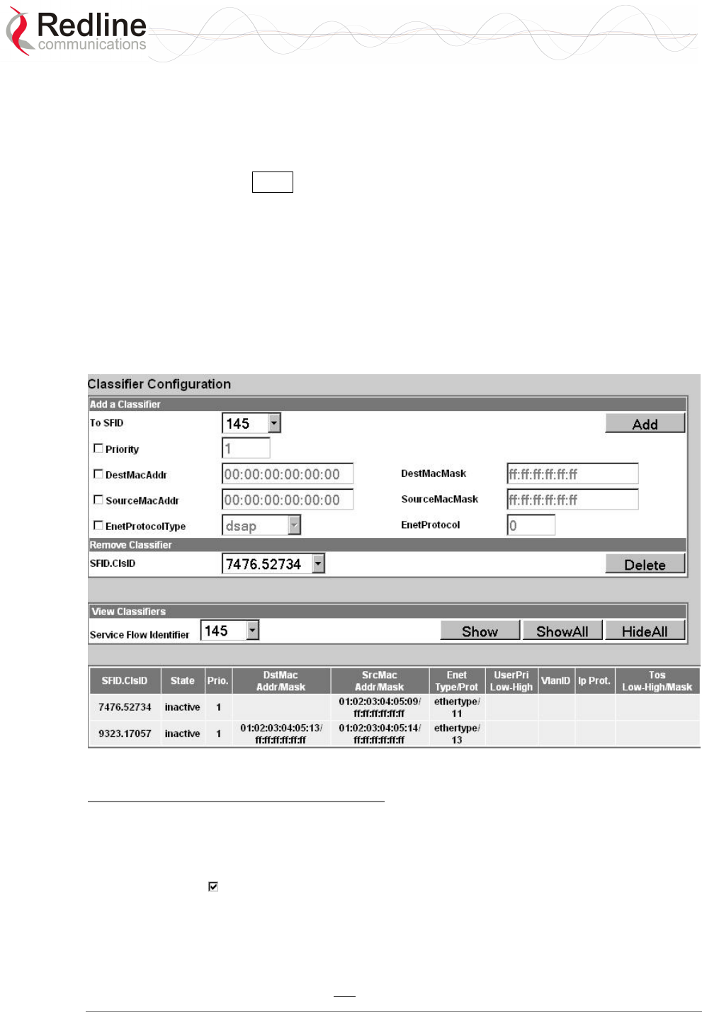
RedMAX™
Base Station
User Manual
Doc. #70-00058-01-01 Proprietary Redline Communications © 2007 July 13, 2007
Page 54 of 119
4.3.4 Classifiers
Click Classifiers in the menu (left side of screen) to view, add and delete service flow
classifiers. Any active service flow must have at least one active classifier. The 802.16
Service Flow can have multiple classifiers (classification rules). New classifiers become
active after clicking the Add button on this screen.
When multiple classifiers are defined for one service flow, the index number is listed in
the form X.Y where:
X == Service Flow index (SfId)
Y == Classifier index number
When a service flow is activated, the classifiers become active by default. A service flow
can have both active and inactive classifiers only when the service flow is already active
and new classifiers are added. New classifiers become active only after they are
successfully implemented on both the base station and the subscriber.
Figure 24: Configuration - Classifier Screen
Classifier Configuration Screen
Add a Classifier
To SFID: Select the index number of the service flow. Refer to the Service Flows
Configuration screen for a list of all service flows.
Priority: Check this box to set a priority for this classifier. When a packet can be
classified by more than one classifier definition, it is classified according to the classifier
with the highest priority setting. Enter a priority value from 0 to 255 (highest priority).
Packets are tested beginning with classifier definition having the highest priority value.
The packet is processed based on the first discovered match. If classifiers have equal
priority, the order of evaluation can not be predicted.

RedMAX™
Base Station
User Manual
Doc. #70-00058-01-01 Proprietary Redline Communications © 2007 July 13, 2007
Page 55 of 119
DestMacAddr: Check this box to enable classification based on a destination MAC
address (downstream traffic from the base station). Enter the MAC address in the
adjacent field. When matched, downlink traffic is sent from the base station using the
associated service flow.
DestMacMask: Enter the mask value (hexadecimal) to be used with the destination
MAC address (DestMacAddr). Valid only if the DestMacAddr is enabled ( ). For
example:
1. A mask value of all ones (ff:ff:ff:ff:ff:ff) will match only the MAC address entered in
the DestMacAddr field.
2. A partially specified mask value will match a range of MAC addresses. For example, a
mask value of 01:02:03:ff:ff:ff will match all MAC addresses where the first 48 bits are
01:02:03. The DestMacAddr should be set to all zeros.
3. A mask of all zeros (00:00:00:00:00:00) will match all destination MAC addresses.
The DestMacAddr field value is not used.
Note: Only one classifier can have a DestMacMask value set to all zeros.
SourceMacAddr: Check this box to enable classification based on a source MAC
address (upstream traffic to the base station). Enter the MAC address in the adjacent
field. When matched, uplink traffic is sent from the subscriber using the associated
service flow.
SourceMacMask: Enter the mask value (hexadecimal) to be used with the source MAC
address (SourceMacAddr). Valid only if SourceMacAddr is enabled ( ).
Examples:
1. A mask value of all ones (ff:ff:ff:ff:ff:ff) will match only the MAC address entered in
the SourceMacAddr field.
2. A partially specified mask value will match a range of MAC addresses. For example, a
mask value of 01:02:03:ff:ff:ff will match all MAC addresses where the first 48 bits are
01:02:03. The SourceMacAddr should be set to all zeros.
3. A mask of all zeros (00:00:00:00:00:00) will match all source MAC addresses. The
SourceMacAddr field value is not used.
Note: Only one classifier can have a DestMacMask value set to all zeros.
EnetProtocolType: Check this box to enable classification based on the protocol
transported by Ethernet. Select Ethernet type from the list: Ethertype for Ethernet version
2 and 802.3 SNAP, and DSAP for 802.3 LLC.
EnetProtocol: Enter the identifier of the protocol transported by Ethernet. Valid only if
an EnetProtocolType is selected. Valid Ethertype values are from 1,501-65,536. Valid
DSAP values are from 0-169 and 171-255. For example, in order to allow IP traffic, set
EnetProtocolType to Ethertype and EnetProtocol to 2048 (0800 hex).
A list of Ethertypes can be found at:
http://www.iana.org/assignments/ethernet-numbers
A list of DSAP values can be found at:
http://www.ethermanage.com/ethernet/enet-numbers/ieee-lsap-list.html.

RedMAX™
Base Station
User Manual
Doc. #70-00058-01-01 Proprietary Redline Communications © 2007 July 13, 2007
Page 56 of 119
Add: Click Add to save the classifier settings.
Note: Classifier settings are effective immediately when created.
Remove Classifier
Service Flow Identifier: Select an existing classifier to be deleted. The format is:
Service Flow ID. Classifier ID
Delete: Click Delete to permanently delete the selected classifier.
View Classifiers
SFID.ClsID: Identifiers for the selected classifier. The format is:
Service Flow ID. Classifier ID
Show: Click Show to display the setting for the service flow selected in the Service
Flow Identifier field.
ShowAll: Click ShowAll to display settings for all service flows.
HideAll: Click HideAll to hide settings for all service flows.
Classifier Table
SFID.ClsID: Identifiers for the selected classifier. The format is:
State: Current state of the service flow:
Active: Classifier is currently active.
Inactive: Classifier is not currently active.
Prio: Priority setting for this classifier.
DestMac: When displayed, classification is based on this destination MAC address.
Addr: Destination MAC address.
Mask: Destination MAC mask.
DestMac: When displayed, classification is based on this source MAC address.
Addr: Source MAC address.
Mask: Source MAC mask.
Enet Type/Prot: When displayed, classification is based on Ethernet protocol type and
protocol.
UserPri: Matching parameters for the Ethernet IEEE 802.1D user priority value
(Ethernet packets with 802.1Q encapsulation). A packet will match if the priority setting
is equal to, or falls between, the high and low range setting. Valid settings are zero to
seven (0 to 7).
Low: Lowest priority setting of range.
High: Highest priority setting of range.
VlanID: Ethernet packet 802.1Q VLAN tag. Valid only if Cs Specification is 802.1Q.
Ip Prot.: IPv4 specification. Valid only if the service class Cs Specification is IPv4.
EnetProtocol: When displayed, classification is based on this Ethernet protocol.
Tos: Matching parameters for the IP type of service/DSCP (IETF RFC 2474). An IP type
of service (ToS) packet will match if the "ip-tos" value, after the mask is applied, is equal
to, or falls between, the high and low range setting. Valid settings are 0 to 7.

RedMAX™
Base Station
User Manual
Doc. #70-00058-01-01 Proprietary Redline Communications © 2007 July 13, 2007
Page 57 of 119
Low: Lowest priority setting of range.
High: Highest priority setting of range.
Mask: A logical 'AND' is performed using the mask and the "ip-tos" value before
testing for range.
SrcIp: Source IPv4 address. Valid only if Cs Specification is IPv4.
Addr: Source IPv4 address network mask.
Mask: Source IPv4 address network mask.
DstIp: IPv4 destination address. Valid only if Cs Specification is IPv4.
Addr: Destination IPv4 address network mask.
Mask: Destination IPv4 address network mask.
DstIp: IPv4 destination address.
Addr Mask: Valid only if Cs Specification is IPv4.
SrcPort: Source IPv4 address port. Valid only if Cs Specification is IPv4.
Start: Lowest port address in range.
End: Highest port address in range.
DstPort: IPv4 destination port address. Valid only if Cs Specification is IPv4.
Start: Lowest port address in range.
End: Highest port address in range.
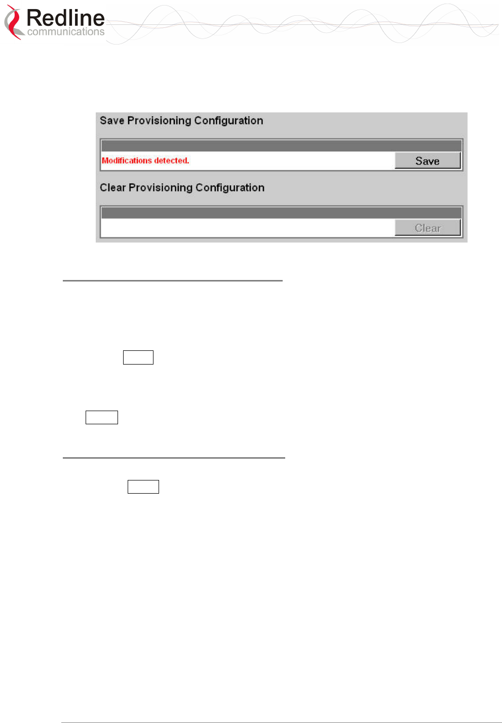
RedMAX™
Base Station
User Manual
Doc. #70-00058-01-01 Proprietary Redline Communications © 2007 July 13, 2007
Page 58 of 119
4.3.5 Manage -- Save Provisioning Information
Click Manage in the menu (left side of screen) to determine if there are unsaved changes
to the service classes, service flows, or classifiers.
Figure 25: Configuration - Save SF Configuration Screen
Save Provisioning Configuration
Save Provisioning Configuration: This screen indicates if there are unsaved changes to
service classes, service flows, or classifiers.
No Modifications Detected: There are no unsaved changes.
Modifications Detected: There are unsaved changes.
Save: Click Save to save all changes. Saving changes will copy all service class, service
flow, and classifier configuration data to non-volatile memory. When the base station is
rebooted, all unsaved changes to the service classes, service flows and classifiers are
discarded.
The Save button control is active only if there are unsaved changes to service classes,
service flows, or classifiers.
Clear Provisioning Configuration
Clear Provisioning Configuration: Clear all service flow configuration data.
Clear: Click Clear to remove all changes made since the last save.
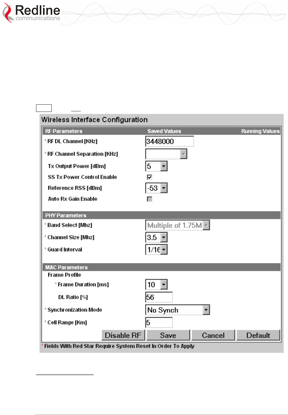
RedMAX™
Base Station
User Manual
Doc. #70-00058-01-01 Proprietary Redline Communications © 2007 July 13, 2007
Page 59 of 119
4.4 Interface Configuration
View and modify the base station settings for the wireless, Ethernet, and management
interfaces.
4.4.1 Wireless Interface
Click Wireless Interface in the menu (left side of screen) to view and modify the base
station MAC, PHY, and RF wireless settings.
Note: Changes to settings marked with a red asterisk (*) are only effective after clicking the
Save button and resetting the base station terminal.
Figure 26: Web: Configuration - Wireless Interface Screen
RF Parameters
RF DL Channel KHz: (*) Enter the channel frequency to use for all subscribers in the
sector. The setting is validated against the type of radio installed. The center frequency
setting can be made in steps of 250 KHz, and the center frequency setting must allow for
RedMAX™
Base Station
User Manual
Doc. #70-00058-01-01 Proprietary Redline Communications © 2007 July 13, 2007
Page 60 of 119
the channel size and not exceed the granted frequency range. For example, when using a
7 MHz channel, the center frequency must be at lease 3.5 MHz inside the band limits.
Important: RF Channel Settings
Operation in the FWA band is subject to license. The radio frequency selections must
be set correctly before the installed system is allowed to transmit. The installed system
must comply with all governing local, regional, and national regulations. Contact
authorities in the country of installation for complete information regarding the licensing
regime and operating restrictions for that regulatory domain.
RF Channel Separation KHz: (*) Select the separation between channels (HD-FDD
radio only) where: UL Channel = DL Channel + Separation.
Tx Output Power dBm: Select the output power level (dBm) of the radio.
Important: RF Power Settings
Operation in the FWA band is subject to license. The radio power selections must be
set correctly before the installed system is allowed to transmit. National Interface
documents may identify a maximum output power for the wireless system, expressed in
terms of an EIRP level that must not be exceeded. The installed system must comply with
all governing local, regional, and national regulations. Contact authorities in the country
of installation for complete information regarding the licensing regime and operating
restrictions for that regulatory domain.
SS Tx Power Control Enable: Check this box to allow the base station to
automatically adjust the transmit power level of subscribers. When enabled, the base
station continually monitors the subscribers and adjusts the transmission power to
maintain a requested RSSI value.
Reference RSS: Select the target value for average Received Signal Strength (RSS) for
subscribers. The Reference RSS setting is the target value for average Received Signal
Strength (RSS) for subscribers RF signals received by the base station. This target value
allows automatic adjustment of the subscriber Tx power for optimum performance with
the minimum of RF interference. The suggested default setting values are indicated in the
following table:
Table 18: System - Wireless Channel Reference RSSI
Channel Size Initial Setting
3.5 MHz -75 dBm
7.0 MHz -72 dBm
These are the suggested initial settings; adjustments to this target value must be made
based on the individual RF characteristics of each deployed sector. The RSSI value
(dBm) for each subscriber can be monitored using the base station SS Info screen (Web
interface). Tx power adjustments are based on a number of factors, and differences of up
to 7 dB may be observed between the Reference RSS setting and measured RSSI.
Auto Rx Gain Enable: Check this box to enable automatic adjustment of the receiver
sensitivity.
PHY Parameters
Band Select MHz: (*) Select channelization type in accordance to 802.16 OFDM PHY
system profiles.
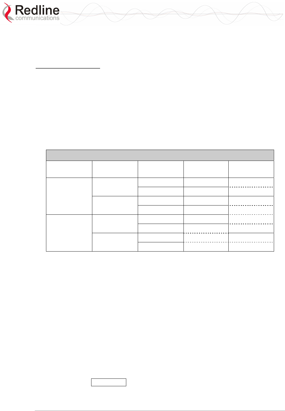
RedMAX™
Base Station
User Manual
Doc. #70-00058-01-01 Proprietary Redline Communications © 2007 July 13, 2007
Page 61 of 119
Channel Size MHz: (*) Select the channel size. Menu selection is based on the type of
radio installed. Refer to the appendices for a list of supported radios.
Guard Interval: (*) Select the cyclic prefix.
MAC Parameters
Frame Profile: Configure the frame size and usage profile.
Frame Duration ms: (*) Select the wireless frame duration (ms). Selections are
based on the channel size. This setting affects the system latency.
DL Ratio %: Enter the downlink usage as a percentage of frame size. This setting
provides traffic shaping on the uplink and downlink traffic profiles.
The DL ratio is dynamic and can be changed at any time without reboot. The DL
Ratio setting in the Wireless Configuration page allows the selection between the
minimum and maximum values specified in the following table (based on Frame
Duration, Channel Bandwidth and Guard Interval settings):
Table 19: System - Wireless Channel Selection (3.4 - 3.6)
Frame Duration
(ms)
Channel Size
(MHz)
Guard Interval Lowest DL
Ratio (%)
Highest DL
Ratio (%)
5 3.5 1/4 58 75
1/16 50
7 1/4 30 80
1/16 25
10 3.5 1/4 26
1/16 25
7 1/4 85
1/16
Synchronization Mode: (*) Select the synchronization mode. Refer to the RedMAX
base station Installation Guidelines for details of the synchronization feature.
No Synch: Synchronization feature is disabled.
Master: This base station provides the master synchronization pulse for each
connected slave base station (without external GPS clock source).
Master with GPS Synchro: This base station is connected to a GPS clock and
provides the master synchronization pulse for each connected slave base station.
Backup - Slave: This slave base station acts as a backup if the master base station
fails to provide synchronization pulses. This feature operates with or without an
external GPS clock connection.
Slave: This base station synchronizes its operations to the synchronization pulse
received from the Master or Backup Master base station.
Cell Range km: (*) Enter the distance to the subscriber located the farthest distance from
the base station.
Disable RF: Click Disable RF to disable the modem output. This is for test purposes
only. The base station terminal must be reset to restore operation of the radio transmitter.

RedMAX™
Base Station
User Manual
Doc. #70-00058-01-01 Proprietary Redline Communications © 2007 July 13, 2007
Page 62 of 119
Save: Click Save to save and apply the current settings. Settings not marked with a red
asterisk are effective immediately. Settings marked with a red asterisk (*) only become
only effective after resetting the terminal.
Cancel: Click Cancel to restore all fields to the last saved values.
Default: Click Default to change all fields to the factory values.
RedMAX™
Base Station
User Manual
Doc. #70-00058-01-01 Proprietary Redline Communications © 2007 July 13, 2007
Page 63 of 119
4.4.2 Ethernet Interface
Click Ethernet Interface in the system menu (left side of screen) to view and configure
the front panel Data and Management (Mgmt) Ethernet ports, and the Intra-Sector Layer-
2 Forwarding (iSL2F) feature.
Figure 27: Web: Configuration - Ethernet Interface Screen
Management: Use this selection to choose which front panel Ethernet port accepts
management traffic.
Via Data port: The Data Ethernet port is used for data and local management traffic.
The Mgt port is disabled.
Via Management port: Only the Mgt Ethernet port is monitored for local
management traffic. Select this mode only when data and management networks are
physically isolated.
Data Port Settings: This setting controls the speed of the Ethernet Data port.
Auto Detect: Auto-negotiate the speed and duplex.
10 Mbps Half Duplex: Operate at 10Base-T half duplex mode only.
10 Mbps Full Duplex: Operate at 10Base-T full duplex mode only.
100 Mbps Half Duplex: Operate at 100Base-T half duplex mode only.
100 Mbps Full Duplex: Operate at 100Base-T full duplex mode only.
Management Port Settings: This setting controls the speed of the Ethernet Management
port.
Auto Detect: Auto-negotiate the speed and duplex.
10 Mbps Half Duplex: Operate at 10Base-T half duplex mode only.
10 Mbps Full Duplex: Operate at 10Base-T full duplex mode only.
100 Mbps Half Duplex: Operate at 100Base-T half duplex mode only.
100 Mbps Full Duplex: Operate at 100Base-T full duplex mode only.
Intra-Sector L2 Forwarding: This feature supports layer 2 network connectivity
between subscribers in a single sector. This capability is also referred to as layer 2 hair-
pinning.
RedMAX™
Base Station
User Manual
Doc. #70-00058-01-01 Proprietary Redline Communications © 2007 July 13, 2007
Page 64 of 119
Disabled Mode: When the Intra-Sector L2 Forwarding feature is disabled, the base
station will not forward traffic between subscribers (hair pinning) or accept traffic
resubmitted to the Ethernet port by an external switch.
External Mode: When external mode selected, the base station will accept traffic
resubmitted to the Ethernet port. This permits an external switch to forward traffic
between hosts located behind subscribers in the same sector.
Internal Mode: When internal mode is enabled, the base station classifies and
forwards traffic between hosts located behind subscribers in the same sector (hair
pinning) without requiring an external switch. Affected traffic is resubmitted directly
to the wireless interface MAC.
Figure 28: Intra-Sector Layer 2 Forwarding -- Internal Mode
Configuration Buttons
Save: Click Save to apply and permanently save the displayed settings.
Cancel: Click Cancel to restore displayed settings to the last saved values.
Default: Click Default to change all displayed settings to the factory default values.
RedMAX™
Base Station
User Manual
Doc. #70-00058-01-01 Proprietary Redline Communications © 2007 July 13, 2007
Page 65 of 119
4.4.3 Management Interface
Click Management Interface in the system menu (left side of screen) to view and edit
the IP address and DHCP settings.
Figure 29: Web: Configuration - Management Interface Screen
IP Parameters
Obtain IP Parameters from DHCP Server: Select this option to have the base station
obtain its IP address from a DHCP server.
Use the following IP Parameters: Select this option to manually enter the following IP
parameters:
IP Address: Enter the static base station network IP address.
Subnet Mask: Enter the base station subnet address mask.
Default Gateway: Enter the IP address of the default gateway on the local Ethernet
segment.
Time Server (SNTP): Enter the IP address of the SNTP server.
Use the following checklist to ensure correct display options:
1. Time server must be compatible with SNTP (RFC-2030)
2. Ensure the time zone is correct for your area.
3. If you are in an area that observes daylight savings time, check the box.
Time Zone: Enter the time offset from GMT (hours).
Daylight Savings: Check this box to enable automatic time change for daylight
savings.
Syslog Server: Enter the IP address of the Syslog server to enable this feature.

RedMAX™
Base Station
User Manual
Doc. #70-00058-01-01 Proprietary Redline Communications © 2007 July 13, 2007
Page 66 of 119
Refresh: Click Refresh Time to poll the time server for the current time.
DHCP Relay Agent Parameters
The subscriber can obtain an IP address from the DHCP server only through an base
station acting as a DHCP Relay Agent. A subscriber can not obtain an IP address from
any DHCP server on the network segment connected to its local Ethernet port. The base
station (acting as a DHCP Relay Agent) can be configured for two different modes:
SS-s should use the same DHCP Server as SC: Select this option to have the base
station forward all subscriber DHCP requests to the DHCP server that the base station
used to obtain its IP address (valid only if field Obtain IP Parameters from DHCP Server
is enabled above).
SS-s should use the following DHCP Server: Select this option to specify the DHCP
server to be used by subscribers.
DHCP Server: Specify the IP address of a DHCP server. The base station forwards
all subscriber DHCP requests to this address.
It important to configure the correct lease options on your DHCP Server:
a) The base station requires option 4, the address of a ToD Server (RFC-868).
b) If you do not wish your devices to display GMT, you must add option 2 (Time Offset).
This is a value denoting the number of seconds to offset your time from GMT. For
example, for the offset of +2 hours you should enter 7200 (some DHCP servers may
require entering hexadecimal value). In North America, EST is -5 hours (-18000 seconds)
from GMT and the negative value must be entered.
Important: The base station must be rebooted to activate changes to the DHCP Relay
Agent settings.
VLAN Management
Enable Management with VLAN Tagged Traffic: Check this box to enable
management using VLAN tagged traffic for the SM CID. This setting is used to
configure tagged management for operation in systems where a single VLAN is used to
control the base station wireless equipment and the user equipment. After enabling this
setting, only traffic with the specified VID is recognized for any management commands.
This setting does not effect operation of the RS-232 Console port.
VLAN ID: Enter the VLAN ID. Only traffic tagged with this VLAN ID is recognized by
the sector controller management process.
Important: The VLAN network support should be verified before enabling this feature.
If the base station is not reachable using the VLAN tagged traffic, the Console port
(RS-232) CLI command must be used to disable this setting.
Save: Click Save to save and apply the current settings.
Cancel: Click Cancel to discard all changes and return to the main screen.
Default: Click Default to set all settings to the factory default settings.
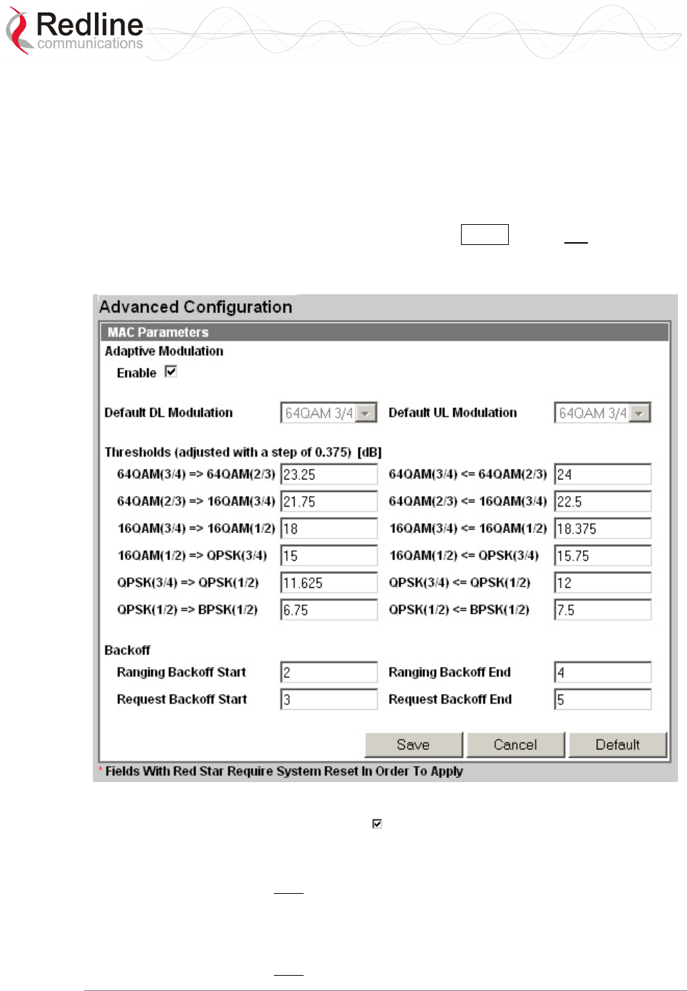
RedMAX™
Base Station
User Manual
Doc. #70-00058-01-01 Proprietary Redline Communications © 2007 July 13, 2007
Page 67 of 119
4.5 Admin Tools
The following screens are used to configure the network settings, passwords, and to
download software updates to the base station.
4.5.1 Advanced Config
Click Advanced Config in the menu (left side of screen) to view and modify MAC
settings for modulation thresholds, and backoff settings. Changes to settings marked with
a red asterisk (*) are only effective after clicking the Save button and rebooting the
terminal. This screen has a separate user name and password.
Note: You must login as 'debug' user to access the Advanced Configuration screen.
Figure 30: Web: Admin Tools - Advanced Configuration Screen
Adaptive Modulation Enable: Check this box to enable adaptive modulation.
Enabling this control disables the default modulation settings.
Default DL Modulation: Select the default modulation and coding rate for the downlink
channel. This value is used only when Adaptive Modulation is disabled. When Adaptive
Modulation is disabled the base station will transmit data only using the selected
modulation/coding.
Default UL Modulation: Select the default modulation and coding rate for the uplink
channel. This value is used only when Adaptive Modulation is disabled. When Adaptive
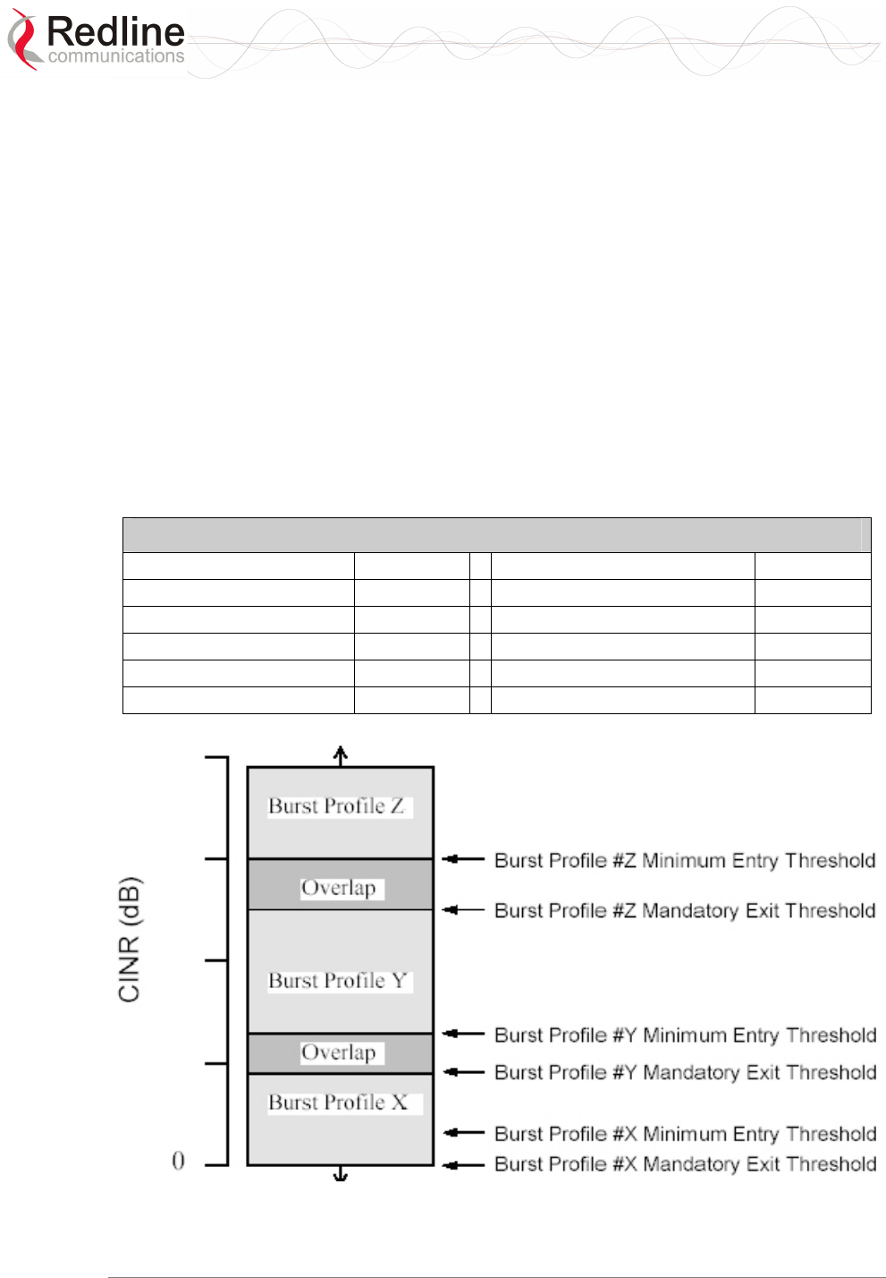
RedMAX™
Base Station
User Manual
Doc. #70-00058-01-01 Proprietary Redline Communications © 2007 July 13, 2007
Page 68 of 119
Modulation is disabled the base station will receive data from subscribers only using the
selected modulation/coding.
Thresholds: Enter the adaptive modulation threshold values (dB) for each modulation
(based on measured CINR). The values are used only when Adaptive modulation is
enabled. There are two entry fields for each threshold setting (row):
- Minimum Entry Threshold (right column)
- Mandatory Exit Threshold (left column)
The modulation/coding is decreased by one step under the following conditions:
1. CINR drops below the exit threshold of the current CINR
2. CINR is between the entry threshold and exit threshold of the current UIUC and CRC
errors are detected in the uplink channel
Settings must be adjusted to match the characteristics of each deployment. Refer to the
following table for recommended threshold settings. These are applicable for independent
sector operation. Co-channel sector deployment in a cell may require further optimization
of the Adaptive Modulation settings.
Table 20: Web: Wireless - Adaptive Modulation Threshold Settings
64QAM 3/4 => 64QAM 2/3 23.25 dBm 64QAM 3/4 <= 64QAM 2/3 24 dBm
64QAM 2/3 => 16QAM 3/4 21.75 dBm 64QAM 2/3 <= 16QAM 3/4 22.5 dBm
16QAM 3/4 => 16QAM 1/2 18 dBm 16QAM 3/4 <= 16QAM 1/2 18.375 dBm
16QAM 1/2 => QPSK 3/4 15 dBm 16QAM 1/2 <= QPSK 3/4 15.75 dBm
QPSK 3/4 => QPSK 1/2 11.625 dBm QPSK 3/4 <= QPSK 1/2 12 dBm
QPSK 1/2 => BPSK 1/2 6.75 dBm QPSK 1/2 <= BPSK 1/2 7.5 dBm
Figure 31: Web: Admin Tools - Advanced Config - Burst Profile Settings
Backoff: Specify ranging and contention periods.

RedMAX™
Base Station
User Manual
Doc. #70-00058-01-01 Proprietary Redline Communications © 2007 July 13, 2007
Page 69 of 119
Backoff settings are used when a subscribers experience collisions during link
establishment or while competing for additional bandwidth. The entered value represents
the binary exponent of the number of 'opportunities' to wait before responding to a base
station registration poll or a bandwidth request opportunity.
It is recommended to not change the Backoff values. Changes to these settings can
severely impact performance of the wireless link. Click the Default button in the
Advanced Config menu to restore the factory backoff settings.
Ranging Backoff Start: Enter the starting backoff window size for initial ranging
contention.
Ranging Backoff End: Enter the final backoff window size for initial ranging
contention.
Request Backoff Start: Enter the starting backoff window size for contention during
bandwidth requests.
Request Backoff End: Enter the final backoff window size for contention during
bandwidth requests.
Save: Click Save to apply and save the displayed settings. Changes to settings marked
with a red asterisk (*) are effective only after the base station is rebooted.
Cancel: Click Cancel to discard all changes and return to the main screen.
Default: Click Default to set all settings to the factory default settings.
Example: How Subscribers Use Backoff Settings
When a subscriber detects a collision during a registration attempt, the subscriber will use
a retry strategy to avoid repeating the collision. Consider the effects of the following
settings:
Ranging Backoff Start = 2
Ranging Backoff end = 4
Following a collision, the subscriber will skip between zero and four registration
opportunities (2Ranging Backoff Start). If the subscriber detects a collision during the retry, it
will skip a random number, between zero and eight registration opportunities (2Ranging
Backoff Start+1). If a third collision is experienced, the subscriber will skip between zero and
sixteen registration opportunities (2Ranging Backoff End). If a fourth collision is detected, the
process repeats as for the first detected collision.
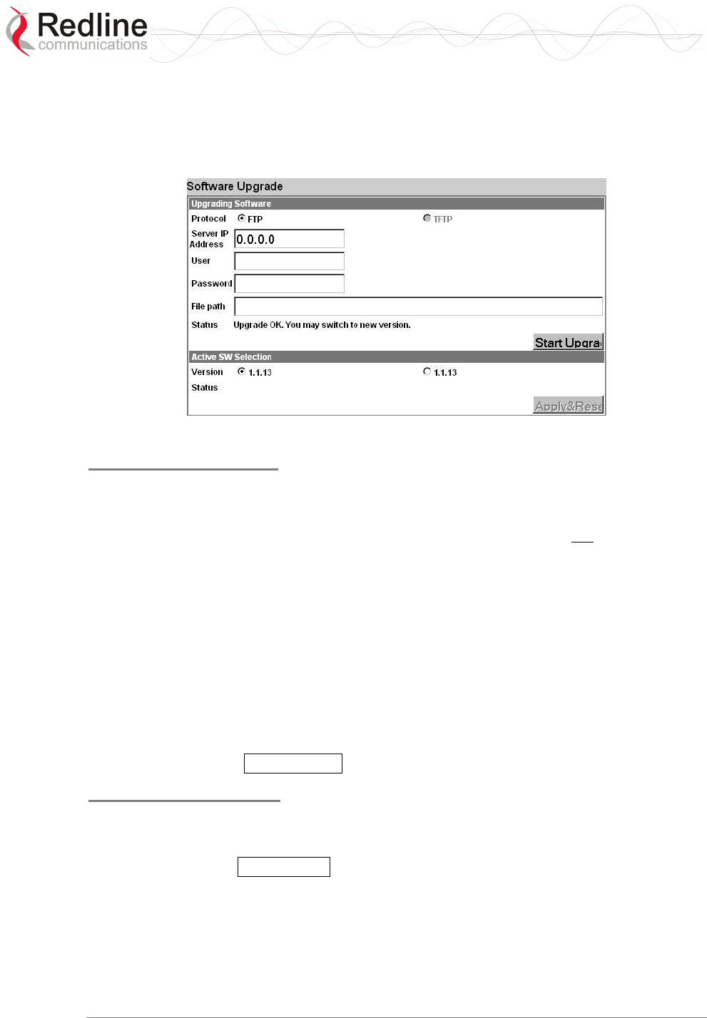
RedMAX™
Base Station
User Manual
Doc. #70-00058-01-01 Proprietary Redline Communications © 2007 July 13, 2007
Page 70 of 119
4.5.2 Software Upgrade
Click Software Upgrade in the menu (left side of screen) to upload a new system
software image from a remote server. The terminal contains two non-volatile RAM banks
for storing the software. Each upload overwrites the standby (unselected) bank.
Figure 32: Web: Admin Tools - Software Upgrade Screen
Upgrading Software
Protocol: Select the type of server:
FTP: Use File Transfer Protocol for file upload.
TFTP: Use Trivial File Transfer Protocol for file upload. TFTP is not available in the
current software version.
Server IP Address: Enter the FTP server network address.
User: Enter the username of a user that is defined on the FTP server and has sufficient
access rights to the base station software image file.
Password: Enter the password for the username entered in the User field above.
File Path: Enter the path and name of the system software image to upload. It is strongly
recommended to copy the binary files to the default file directory for the FTP server and
to specify only the file name in this field.
Status: Monitors the software upload operation.
Start Upgrade: Click Start Upgrade to begin the software upload.
Active SW Selection
Version: Select the software image to load on the next system reset.
Status: Monitors the system upgrade operation.
Apply&Reset: Click Apply&Reset to save the current version selection.

RedMAX™
Base Station
User Manual
Doc. #70-00058-01-01 Proprietary Redline Communications © 2007 July 13, 2007
Page 71 of 119
Before Beginning the Upgrade
Use the following procedures to upgrade the base station.
The following items must be addressed before beginning the upgrade:
1. You must obtain the latest base station binary files. You must copy the binary files
into the default file location for the FTP server. You can not specify a 'path' in the
upgrade dialog.
2. The base station performs all software upgrades using an FTP server:
a) The FTP server must be located on the network connected to an active
Ethernet port (Data or Mgmt) on the base station.
b) The FTP server must have a user defined as follows:
username: target
password: secret
Upgrade Base Station
1. Start a Web browser session to the base station and login. The factory default
settings are as follows:
Login: admin
Password: admin
2. Click Software Upgrade in the left-hand menu and make the following settings:
Protocol: FTP
Server IP address: [enter address of FTP server]
User: target
Password: secret
File Path: [Enter binary file name -- including .bin extension]
3. Click Upgrade button and wait for the base station to download and save the binary
file. This process may take a few minutes. Progress is indicated in the Status field.
The Status Screen displays 'Update OK' when the upgrade is complete.
4. In the Software Upgrade screen, Click radio to select the new version of software.
Click Apply&Reset to activate the new software. Click Yes in the confirmation
dialog.
Note: When the base station is reset, all traffic stops for about 30 seconds and then
resumes as the subscribers are registered.
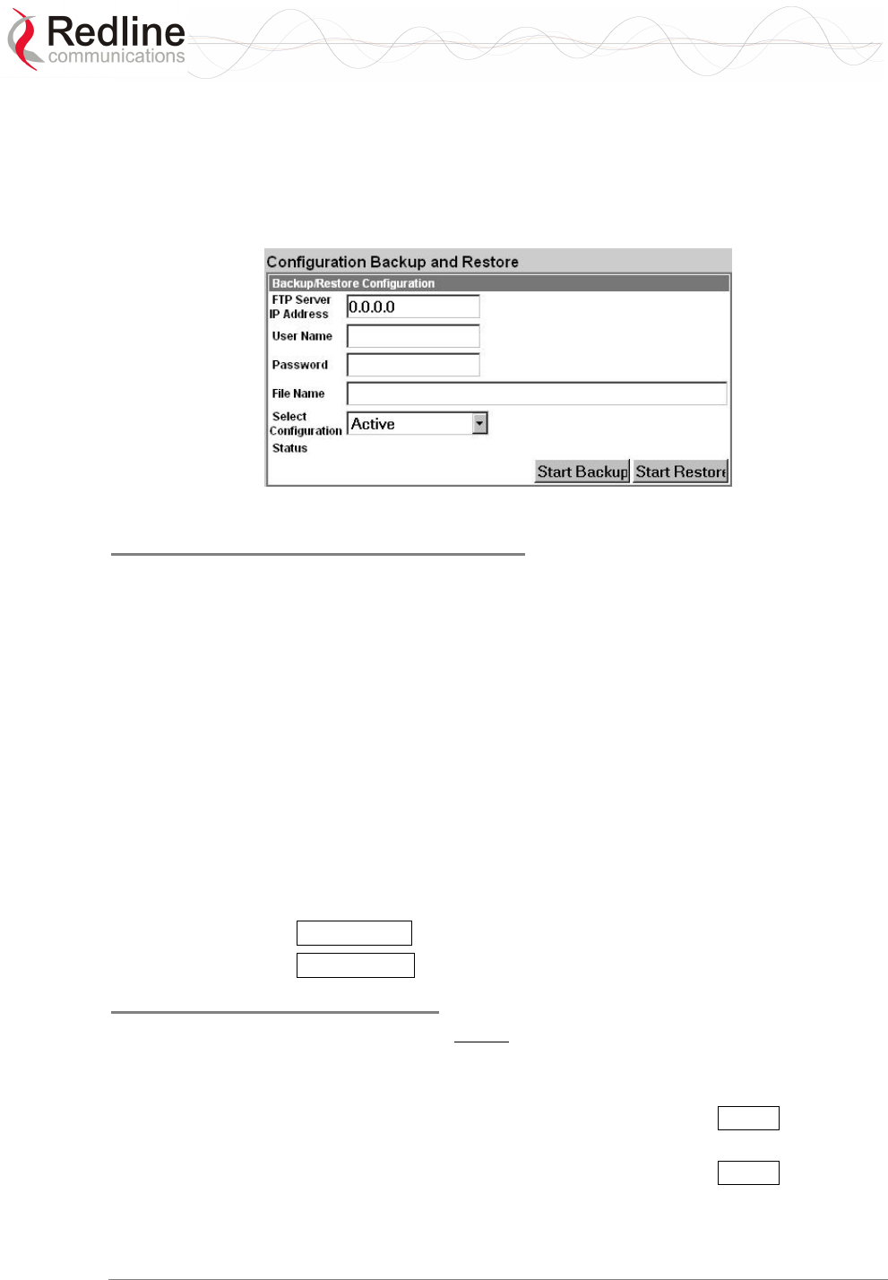
RedMAX™
Base Station
User Manual
Doc. #70-00058-01-01 Proprietary Redline Communications © 2007 July 13, 2007
Page 72 of 119
4.5.3 Backup and Restore
Click Backup and Restore in the menu (left side of screen) to manage the base station
saved settings. The configuration settings for the active and alternate software loads can
be saved to a network server reachable by the base station. Configuration files saved on a
remote server can be used to restore settings on a base station.
Figure 33: Web: Admin Tools - Software Upgrade Screen
Backup and Restore Configuration
FTP Server IP Address: Enter the FTP server network address.
User Name: Enter the username of an account on the FTP server. This user must have
access rights to read and write files on the server.
Password: Enter the password for the user account.
File Name: Enter the path and file name of the configuration file to save or read.
When performing a backup, it is strongly recommended to use the default file
directory for the FTP server and enter only the file name in this field. It is also
recommended to specify a file name that includes the date and software revision.
Select Configuration:
Active: Save/restore the saved configuration for the active software load.
Alternate: Save/restore the saved configuration for the inactive software load.
Status: Displays status messages for the current operation.
Start Backup: Click Start Backup to save the selected settings (Active/Alternate).
Start Restore: Click Start Restore to restore the selected settings (Active/Alternate).
Before Beginning a Backup
The following items must be addressed before beginning the backup:
1. The settings to be saved on a remote server must be saved in the memory bank
associated with the software binary file. To be sure that all current settings are saved:
a) Click Manage in the menu (left side of screen) and click Save to save all
changes (if button is active).
b) Click Manage in the menu (left side of screen) and click Save to save all
changes (if button is active).
2. The base station performs all software upgrades using an FTP server:

RedMAX™
Base Station
User Manual
Doc. #70-00058-01-01 Proprietary Redline Communications © 2007 July 13, 2007
Page 73 of 119
a) The FTP server must be located on the network connected to an active Ethernet
port (Data or Mgmt) on the base station.
b) The FTP server must have a user account with read/write privileges.
Backup Base Station Settings
Use the following steps to backup the base station settings:
1. Start a Web browser session to the base station and login. The factory default
settings are as follows:
Login: admin
Password: admin
2. Click Backup and Restore in the menu and make the following settings:
User Name: Enter the username of a user that is defined on the FTP server and has
sufficient access rights to the read and write files.
Password: Enter the password for the user account.
File Name: Enter the path and name of the file to save.
When performing a backup, it is strongly recommended to use the default file
directory for the FTP server and enter only the file name in this field. It is also
recommended to specify a file name that includes the date and software revision.
Select Configuration: Select Active or Alternate.
3. Click Start Backup and wait for the base station to transfer the configuration file.
This process may take a few minutes and progress is indicated in the Status field.
Restore Base Station Settings
Use the following steps to restore the base station settings:
1. Start a Web browser session to the base station and login. The factory default
settings are as follows:
Login: admin
Password: admin
2. Click Backup and Restore in the menu and make the following settings:
User Name: Enter the username of a user that is defined on the FTP server and has
sufficient access rights to the read and write files.
Password: Enter the password for the user account.
File Name: Enter the path and name of the file to be restored.
Select Configuration: Select Active or Alternate.
3. Click
Start Restore and wait for the base station to transfer the configuration file.
This process may take a few minutes and progress is indicated in the Status field.
4. If the restore operation was successful, and the destination was the Active memory
bank, the base station is automatically rebooted. When the base station is rebooted,
all traffic stops for about 30 seconds and then resumes as the subscribers are
registered.
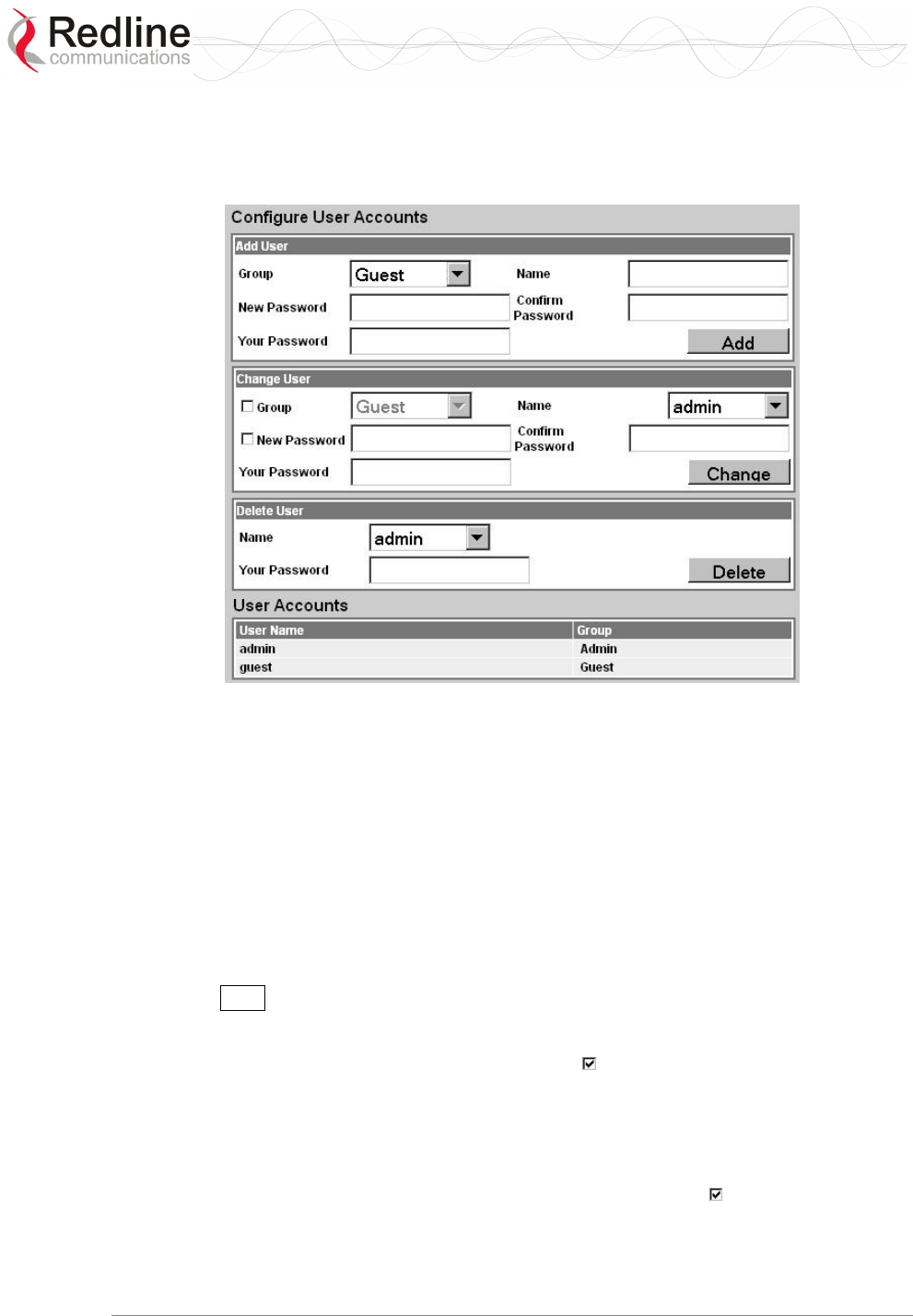
RedMAX™
Base Station
User Manual
Doc. #70-00058-01-01 Proprietary Redline Communications © 2007 July 13, 2007
Page 74 of 119
4.5.4 System Account Management
Click Accounts Management in the menu (left side of screen) to change the system
access password.
Figure 34: Web: Admin Tools - System Password Screen
Add User
Group: Select the group for this account.
Admin: This account user is an administrator.
Guest: This account user is a guest.
Name: Enter the name for this account.
New Password: Enter a new password.
Confirm Password: Re-enter the new password.
Your Password: Enter your login password.
Add: Click Add to create a new account using these settings.
Change User
Group: To change the group for this account, check this box and select a new group.
Admin: This account user is an administrator.
Guest: This account user is a guest.
Name: Select the name of an existing account to change.
New Password: To change the password for this account, check this box and enter a
new password for this account.
Confirm Password: If changing the password, re-enter the new password in this field.
Your Password: Enter your login password.

RedMAX™
Base Station
User Manual
Doc. #70-00058-01-01 Proprietary Redline Communications © 2007 July 13, 2007
Page 75 of 119
Change: Click Change to create a new account using these settings.
Delete User
Name: Select the name of an existing account to be deleted.
Your Password: Enter your login password.
Delete: Click Delete to create a new account using these settings.
User Accounts
Old Password: Enter the current password.
New Password: Enter a new password.
Confirm Password: Re-enter the new password.
Your Password: Enter your login password.
Change: Click Change to save and apply changes.
Note: To delete an administrator account, you must login using another administrator
account. To delete an administrator account: 1) change the account to be deleted to type
'guest', 2) delete the account.
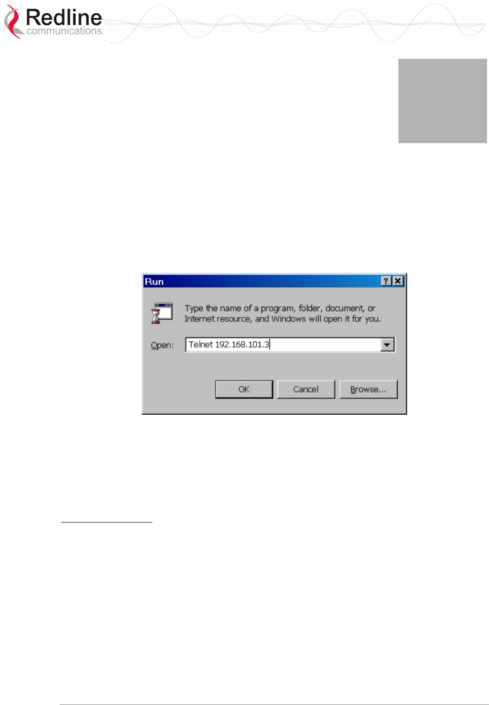
RedMAX™
Base Station
User Manual
Doc. #70-00058-01-01 Proprietary Redline Communications © 2007 July 13, 2007
Page 76 of 119
Chapter
5
5
5
C
CL
LI
I
I
In
nt
te
er
rf
fa
ac
ce
e
The base station can be configured and monitored using the command line interface
(CLI) commands. This section describes the procedures for configuring and operating the
base station using the CLI over a Telnet connection.
5.1 Connecting via Telnet
To connect to the base station, open a Telnet session to the IP address of the base station
(default address is 192.168.101.3).
Figure 35: CLI - Connecting via Telnet
When the command prompt screen appears, login using the following (factory default) :
Username: admin
Password: admin
The base station may now be controlled using a set of CLI commands.
Telnet Logout
Exit from a CLI session by typing:
logout ENTER
The system will logout users automatically if no commands are received (idle) for five
minutes.
5.2 CLI Commands
The system defaults to root mode when you login to the base station. The following table
lists all base station specific commands available in root mode. All commands are case-
sensitive.
The following table lists commands available in the root directory. These commands are
described in detail in the following sections.
RedMAX™
Base Station
User Manual
Doc. #70-00058-01-01 Proprietary Redline Communications © 2007 July 13, 2007
Page 77 of 119
Table 21: CLI - Command Summary
Command Description
debug* Intermediate node for debugging commands
defaultSF* Temporarily enable or disable default uplink service flows
diagStatistics* Access the Diagnostic Status data structure
interfaces View and configure the data and management Ethernet ports
ipAddress View and configure the IP address data structure
logout Exit from Command Line Interface
monitor Enter monitor mode (press any key to exit monitor mode)
reboot Reboot the device box.
remoteFSInit* Initialize remote File System
resetSS* Reboot the base station
set Command mode to view and configure system settings
show Command mode to view system settings
softwareConf Backup/restore base station settings to/from FTP server
softwareUpgrade Download software and select the active version
user View and configure user accounts
vxShell* Switch to VxWorks target shell
wmanIfBs View and configure wireless MAN interface objects
wmget* Set WindMark, with instance/argument support
wmlist* Set WindMark, with instance/argument support
wmnext* Set WindMark, with instance/argument support
wmset* Set WindMark, with instance/argument support
x509 WMAN-IF-MIB X509 certificate data
*Debug user only.
5.2.1 Common Controls
Use the following CLI control commands in all configuration modes.
Table 22: CLI - Root Mode Commands
Command Description
?
Use the '?' character to display help for any command or mode.
Example: From the root directory, enter the following command to list all
parameters that can be changed using the 'set' command:
set ?
CTRL-Z Return to root mode.
Cancel command entry (alternative to backspace delete).
Return to parent node / mode. exit
all (exit all) Return to parent mode.
logout Terminate this telnet session. May be entered from any mode.

RedMAX™
Base Station
User Manual
Doc. #70-00058-01-01 Proprietary Redline Communications © 2007 July 13, 2007
Page 78 of 119
5.2.2 debug
The debug command is used to view diagnostic information for the AN-100u base
station.
Table 23: CLI - Interface Command
Command Parameter/Description
debug dump - Save the information to the specified FTP server.
<Server> - IP Address of the Server to dump data to
<File> - File Name of the dump data
mode - Show/change the current debug mode setting.
level - <normal(0) | monitoring(1) | debug(2)>
server - IP address of the default FTP server for automatically
debug info dump upon system errors.
reset - Reset the DEBUG data structure content.
CrcErrors - absolute
SymErrors - absolute
DlSdus - absolute
UlSdus - absolute
DlMpdus - absolute
UlMpdus - absolute
DlSecMgm - absolute
UlSecMgm - absolute
DlDefaultSdus - absolute
UlDefaultSdus - absolute
Fpc - absolute
Bwr - absolute
Pgb - absolute
rxmode - Set to continuous receive mode.
show - Display DEBUG data structure content.
FrameNumber - RO -- MAC statistics;
Stations - RO -- MAC statistics;
UlServiceFlows - RO -- MAC statistics;
DlServiceFlows - RO -- MAC statistics;
DlUsage - RO -- MAC statistics;
UlUsage - RO -- MAC statistics;
CrcErrors - Resetable -- MAC statistics;
SymErrors - Resetable -- MAC statistics;
DlSdus - Resetable -- MAC statistics;
UlSdus - Resetable -- MAC statistics;
DlMpdus - Resetable -- MAC statistics;
UlMpdus - Resetable -- MAC statistics;
DlSecMgm - Resetable -- MAC statistics;
UlSecMgm - Resetable -- MAC statistics;
DlDefaultSdus - Resetable -- MAC statistics;
UlDefaultSdus - Resetable -- MAC statistics;
Fpc - Resetable -- MAC statistics;
Bwr - Resetable -- MAC statistics;
Pgb - Resetable -- MAC statistics;
Cinr - RO -- PHY statistics;
Rssi - RO -- PHY statistics;
Fofs - RO -- PHY statistics;
Corb - RO -- PHY statistics;
mac - Display MAC subgroup statistics.
phy - Display MAC subgroup statistics.
monitor - Enter into monitor mode, press any key to exit.
txmode - Set to continuous transmit mode.

RedMAX™
Base Station
User Manual
Doc. #70-00058-01-01 Proprietary Redline Communications © 2007 July 13, 2007
Page 79 of 119
5.2.3 interfaces
The interfaces command is used to view and configure the front panel Data and
Management (Mgmt) Ethernet ports.
Table 24: CLI - Interfaces Command
Interface
Command Parameter/Description
ethernet Ethernet port settings.
IntSep Select integrated or separated management mode.
0: The Data Ethernet port is used for data and local
management traffic. The Mgt Ethernet port is
disabled.
1: Only the Mgt Ethernet port is monitored for local
management traffic. Select this mode only when data
and management networks are physically isolated.
DataDuplex Data Ethernet port settings.
0: Auto-detect speed and duplex.
1: Operate at 10Base-T half duplex mode only.
2: Operate at 10Base-T full duplex mode only.
3: Operate at 100Base-T half duplex mode only.
4: Operate at 100Base-T full duplex mode only.
MgmDuplex Management Ethernet port settings.
0: Auto-detect speed and duplex.
1: Operate at 10Base-T half duplex mode only.
2: Operate at 10Base-T full duplex mode only.
3: Operate at 100Base-T half duplex mode only.
4: Operate at 100Base-T full duplex mode only.
Intra-
SectorL2Forwar
Establish a virtual private network at layer 2 between any
number of subscriber CPEs in single sector.
0: Disabled - base station will not accept traffic
resubmitted to the Ethernet port
1: Internal - base station creates a service flow to
provide transparent tunneling for higher-layer
protocols
2: External - base station allows an external switch to
forward VLAN traffic back through the (originating)
base station Ethernet port and over the wireless.
default Restore all settings to factory default values.
management Management configuration settings.
LocalIp Enter the static base station network IP address.
LocalMask Enter the base station subnet address mask.
DefGateway Enter the IP address of the default gateway on the local
Ethernet segment.
DhcpEnable :
0: Manually enter the following IP parameters
1: Have the base station obtain its IP address from a
DHCP server.
ToDIP Enter the IP address of an the SNTP server.

RedMAX™
Base Station
User Manual
Doc. #70-00058-01-01 Proprietary Redline Communications © 2007 July 13, 2007
Page 80 of 119
Table 24: CLI - Interfaces Command
Interface
Command Parameter/Description
TimeZoneHourEnter the offset (hours) from GMT.
TimeZoneMinuteEnter the offset minutes (fraction) from
GMT.
DayLightSavingsEnable automatic time change for
daylight savings.
0: Disabled
1: Enabled
SysLogIPEnter the IP address of the System Log server.
DhcpServIPUsrSpecify the IP address of a DHCP server.
The base station forwards all subscriber DHCP requests to
this address.
DhcpTypeSet the DHCP relay type.
0: Base station forwards all subscriber DHCP requests
to the DHCP server that the base station used to
obtain its IP address.
1: Subscriber to use the specified DHCP server. Use
DhcpServIPUs to specify the DHCP server to be used by
subscribers.
MgmtVLANEnable or disable management using VLAN
tagged traffic.
0: Disable tagged management.
1 Enable tagged management.
VlanIdEnter the VLAN ID (VID) for the management
VLAN.
defaultRestore all settings to factory default values.
wireless Wireless interface configuration settings:
set Modify settings.
RfDLChannel - <3400000 - 3600000; step=250>
RfSeparation - <-100000 - 100000; step=50000>
RfTxOutputPower - <0 - 23; step=1>
RefRSS Enter the reference RSS value
SSTxPowerControl - 0 -- disable; 1 -- enable
RfAutoRxGainEnable - 0 -- disable; 1 -- enable
PhyClk 80 -- UnlicensedProprietary
84 -- Multiple_Of_1.5MHz
91 -- Unlicensed
96 -- Multiple_Of_1.75MHz
ChannelBandwidth
5 -- 7 Mhz
6 -- 3.5 Mhz;
CyclicPrefix (phyCp)
0 -- 1/32
1 -- 1/16
2 -- 1/8
3 -- 1/4

RedMAX™
Base Station
User Manual
Doc. #70-00058-01-01 Proprietary Redline Communications © 2007 July 13, 2007
Page 81 of 119
Table 24: CLI - Interfaces Command
Interface
Command Parameter/Description
MacMaxDistance maximum distance to any subscriber
MacFrmDuration
0 -- 2.5
1 -- 4
2 -- 5
3 -- 8
4 -- 10
5 -- 12.5
6 -- 20
MacSyncMode
0 -- NoSynch
1 -- Master with GPS Synch
2 -- Master
3 -- Slave
4 -- Backup Slave
MacAirInterfaceStatu - 0 -- disable RF; 1 -- enable RF
MacDLRatio downlink ratio (25 - 80)
default restore all settings to factory default values
show Display the general wireless configuration.
5.2.4 ipAddress
The ipAddress command is used to view and configure the base station IP address
parameters.
Table 25: CLI - IP Address Command
Command Parameter/Description
set Modify the base station network IP settings.
Address: <IP Address> Enter new IP address.
XXX.XXX.XXX.XXX
Mask: <IP Mask> Enter new Netmask value.
XXX.XXX.XXX.XXX
Dhcp: Enable or disable DHCP support.
0: - Static address
1: - DHCP allocated address.
Gateway < Default gateway> Enter new gateway address. Requires
confirmation to proceed.
show Display all IP address information.
RedMAX™
Base Station
User Manual
Doc. #70-00058-01-01 Proprietary Redline Communications © 2007 July 13, 2007
Page 82 of 119
5.2.5 monitor
The monitor command is used to remotely view a dynamically updated screen of
statistics for the base station.
Table 26: CLI - Monitor Command
Command Parameter/Description
monitor Dynamic display of base station statistics values. For example:
MacFrameNumber: 11296
MacStations: 5
MacUlServiceFlows: 3
MacDlServiceFlows: 3
MacDlUsage: 7 %
MacUlUsage: 3%
MacCrcErrors: 0
MacSymErrors: 0
MacDlSdus: 3590
MacUlSdus: 1889
MacDlMpdus: 3574
MacUlMpdus: 2378
MacArqReTx: 0
MacBcstSdus: 0
MacSecMgmPkts: 132
MacFpc: 9
MacBwr: 1928
MacPgb: 0
PhyCinr: 31.5 dB
PhyRssi: -12.0 dBfs
PhyFofs: 183 Hz
PhyCorb: 0
5.2.6 reboot
The reboot command is used to remotely reset the base station.
Table 27: CLI - Reboot Command
Command Parameter/Description
reboot Reset the AN-100 equipment. Confirmation is required..
5.2.7 set
The set command is used to control selected fields.
Table 28: CLI - Set Command
Command Parameter/Description
ipAddress See the ipAddress command.
privacy Change privacy related settings on SC.
TrustAll: 0 -- no
1 -- yes.
UseTestTimers: 0 -- Use normal default timer settings
1-- Use factory test timer settings.
sysContact Change the system administrator contact information (255 chars max).
<val_sysLocation> Enter the location string for this device.
sysLocation Change the system administrator contact information (255 chars max).
<val_sysLocation>: Enter the location string for this device (255 chars
max.).
sysName Change the system name (255 chars max).
<val_sysname>: Enter the system name for this device.
variable Set CLI session variables.

RedMAX™
Base Station
User Manual
Doc. #70-00058-01-01 Proprietary Redline Communications © 2007 July 13, 2007
Page 83 of 119
5.2.8 show
The show command is used to display operating information about the base station.
Table 29: CLI - Show Command
Command Parameter/Description
eventLog Display system logging events. For example:
Time:.........................Tue May 23 14:17:39
Txt:..........................Radio Type 1: TB3435F7
Time:.........................Tue May 23 14:17:36
Txt:..........................RedMax AN-100U Ver. 1.0.58 started.
ifCounters Display counter statistics of device interfaces. For example:
Structure --- <<Interface statistics>>
64 bits Ingress Counters 64 bits Egress Counters
Octets:........................0 Octets:........................0
UcastPkts:...............1876059 UcastPkts:................881643
MulticastPkts:.................0 MulticastPkts:.................0
BroadcastPkts:.................0 BroadcastPkts:............583368
Others
Name:.....................Signal InDiscards:....................0
InMulticastPkts:...............0 InErrors:....................350
InBroadcastPkts:...............0 OutDiscards:...................0
OutMulticastPkts:..............0 OutErrors:.....................0
OutBroadcastPkts:.........583368
ifStatus Display status of device interfaces. For example:
Structure --- <<Interface Status>>
Descr:........... 802.16
Type:............... propBWAp2Mp(184
Mtu:.................. 2048
Speed:.............. 16940000
PhysAddress:.... 0:09:02:00:89:
AdminStatus:..... up(1)
OperStatus:...... up(1)
LastChange:...... 00:00:13
interfaces Display device interfaces. For example:
Index Description MAC Address
1 802.16 00 09 02 00 89 c1
2 802.3 00 09 02 00 89 c1
3 802.3 00 09 02 00 89 c1
ipAddress Display the IP address data.
Address: <IP Address> - IP Address
Mask: <IP Address> - Subnet Mask.
Dhcp: Enable/disable DHCP support.
0: Static address entered by user.
1: DHCP allocated address.
Gateway: <IP Address> - Default GatewayAddress.
If no field name is specified, the whole data structure is displayed. For
example:
Structure --- <<SC IP Address Data>>
Address:......................192.168.20.97
Mask:.........................255.255.255.0
Dhcp:.........................StaticIP(0)
Gateway:......................192.168.20.250
sfInfo Display service flow info.
<MAC Address> - Specify the subscriber MAC address

RedMAX™
Base Station
User Manual
Doc. #70-00058-01-01 Proprietary Redline Communications © 2007 July 13, 2007
Page 84 of 119
Table 29: CLI - Show Command
Command Parameter/Description
downlink - Display downlink service flow information.
uplink - Display uplink service flow information.
For example:
AN-100U(show->)#> sfInfo 00:09:02:00:8c:7f downlink
<< SF Information >>
--- Downlink ---
IfBsSfId:.....................5106 ScSchedulingType:.......bestEffort(2)
MaxSustainedRate:.............800000 bps ScArqEnable:.............false(2)
MinReservedRate:..............0 bps SfInfoOctets:..............251088824
MaxLatency:...................0 ms SfInfoTrafficRate:.......787 Kbps
TrafficPriority:..............1 SfInfoPkts:..................256244
ssInfo Display information about selected/all subscribers. If no MAC address is
entered, information for all subscribers is returned. For example:
<MAC Address> - Specify the subscriber MAC address
<< SS Information >>
MAC Address:..................00:09:02:00:a1:21 SignalNoise:..................29.6 dB
IpAddress:....................192.168.20.30 SignalNoiseMax:...............31.1 dB
BasicCid:.....................47 SignalNoiseMin:...............23.2 dB
DownChannelModCode:...........64QAM(3/4)(6) CrcErr:.......................0
SsInfDownlinkRate:............12705 Kbps AntennaRsl:...................-54 dBm
UpChannelModCode:.............64QAM(3/4)(6) Distance:.....................0 m
SsInfUplinkRate:..............12705 Kbps
status Display Wireless Interface information. For example:
Structure --- <<Wireless Interface Status>>
Downlink Status Uplink Status
Traffic:....................1575 kbps Traffic:....................1600 kbps
BandwidthMargin:...6220 kbps BandwidthMargin:......4924 kbps
Others
Cinr: 31.1 dB AirInterfaceStatus: enabled(1)
RfTxPower 5 dBm ScSynchroStatus: noSynchro(0)
IduTemp 49 Celsius RegisteredSSs: 5
OduTemp:. 54 Celsius ReferenceRss: -53
HcsErrors: 0 PowerSupplyStatus: A-On(1)
CrcErrors: 421 FansStatus: oneFanOn(1)
sysContact Display contact info of system administrator. For example:
sysContact: Central Office AA34
sysDescr Display info about system hardware and software. For example:
sysDescr:RedMax AN-100U
sysName Display system name. For example:
sysName:Base Station AA34
sysUpTime Display system time running since last reboot. For example:
sysUpTime:02:00:20
version Display the running software version.
Current S/W version: 1.2.11
==> Built on: May 3 2007, 18:43:06

RedMAX™
Base Station
User Manual
Doc. #70-00058-01-01 Proprietary Redline Communications © 2007 July 13, 2007
Page 85 of 119
5.2.9 softwareConf
The softwareConf command is used to load new software binary files on the base station.
See section 4.5.2: Software Upgrade on page 70.
Table 30: CLI - Software Upgrade Command
Command Parameter/Description
backup Save a backup copy of the base station settings on a remote FTP server.
Server: IP Address of the FTP server.
File: Use this name when saving the configuration backup file.
Which: Specify the settings to be saved:
0 - Alternate configuration.
1 - Active configuration.
For example:
backup 192.168.20.100 BS_024-061108.cfg 1 <ENTER>
You will be prompted by the FTP server to enter a valid username and
password.
restore Restore the base station settings using a backup copy previously saved on a
remote FTP server.
Server: IP Address of the FTP server.
File: Use this name when saving the configuration backup file.
Which: Specify the settings to be saved:
0 - Alternate configuration.
1 - Active configuration.
For example:
restore 192.168.20.100 BS_024-061108.cfg 1 <ENTER>
You will be prompted by the FTP server to enter a valid username and
password.
5.2.10 softwareUpgrade
The softwareUpgrade command is used to load new software binary files on the base
station. See section 4.5.2: Software Upgrade on page 70.
Table 31: CLI - Software Upgrade Command
Command Parameter/Description
loadimage Download software image and write into flash.
Server: <IP address> - Address of ftp server
File: <filename.bin> - Enter file name (including .bin extension).
show Display the S/W version information in the device. For example:
First Version: 1.0.53
Second Version:. 1.0.53 <ACTIVE>
==> Built on: Apr 19 2006, 11:19:24
switch Switch between the active and inactive software versions. Requires user
confirmation to proceed.

RedMAX™
Base Station
User Manual
Doc. #70-00058-01-01 Proprietary Redline Communications © 2007 July 13, 2007
Page 86 of 119
5.2.11 user
The user command is used to modify the user profiles and passwords.
Table 32: CLI - User Command
Command Parameter/Description
access Change user access level
name <username> - User login name
<access> - Access level (0-10)
add Add a user
name <username> - User login name to be added
<access> Access level
delete Delete a user
name <username> - User login name to be deleted
Note: To delete an administrator account: 1) change the account to be deleted
to access level '0' (guest), 2) delete the account.
password Change user password. User is required to enter/confirm new password for this
account.
<username> - User login name
show Show all users. For example:
User: admin Access: 10 (Administrator level)
User: guest Access: 0 (Guest access level)
5.2.12 wmanlfBs
The wmanlfBs command is used to …
Table 33: CLI - WmanlfBs Command
Command Parameter/Description
classifier View or modify the wmanIfBsClassifierRuleTable.
add add an instance to the wmanIfBsClassifierRuleTable
delete remove an instance from the wmanIfBsClassifierRuleTable
show display one or all instances in the wmanIfBsClassifierRuleTable
provForSf View or modify the wmanIfBsSsProvisionedForSfTable.
add add an instance to the wmanIfBsSsProvisionedForSfTable
delete remove an instance from the wmanIfBsSsProvisionedForSfTable
show display one/all entries in the wmanIfBsSsProvisionedForSfTable
saveAll Save into non-volatile memory any changes to the SF configuration setting.
serviceClass View or modify the wmanIfBsServiceClassTable.
add add an instance to the wmanIfBsServiceClassTable
delete remove an instance from the wmanIfBsServiceClassTable
show display one or all instances in the wmanIfBsServiceClassTable
sf View or modify the wmanIfBsProvisionedSfTable.
add add an instance to the wmanIfBsProvisionedSfTable
delete remove an instance from the wmanIfBsProvisionedSfTable
show display one or all instances in the wmanIfBsProvisionedSfTable
ssConfig View or modify the subscriber information.
add Add an entry of Subscriber Station info.

RedMAX™
Base Station
User Manual
Doc. #70-00058-01-01 Proprietary Redline Communications © 2007 July 13, 2007
Page 87 of 119
Table 33: CLI - WmanlfBs Command
Command Parameter/Description
delete Remove Subscriber Station info entries.
edit Modify an existing entry of Subscriber Station info.
show Display Subscriber Station info entries.
5.2.13 x509
The x509 command is used to manage the privacy sublayer certificates.
Table 34: CLI - x509 Command
Command Parameter/Description
x509 add Download new certificates into the device. (FTP setup required)
<Server> IP Address of the Server to download certificates from
<File> Certificate file name. (i.e. *.cer or *.pem)
delete Delete one of or all the certificates from the device non-volatile memory.
<Index> To remove the certificate item specified by Index, -1 for
removing all.
All To remove all the certificates (Index must be specified as -1).
Yes Confirmation to proceed
show Display a list of certificates stored in non-volatile memory.

RedMAX™
Base Station
User Manual
Doc. #70-00058-01-01 Proprietary Redline Communications © 2007 July 13, 2007
Page 88 of 119
Chapter
6
6
6
O
Op
pe
er
ra
at
ti
io
on
na
al
l
N
No
ot
te
es
s
6.1 Self-Provisioning Features
6.1.1 Default Service Flows
The base station automatically creates one default uplink and downlink service flow for
each registered subscriber. The default service flows pass initial traffic (i.e., DHCP
Discovery or PPPoE Initiation) from hosts connected to subscriber. The default service
flows have the lowest QoS settings and the associated classifiers have the lowest priority.
The sector-wide bandwidth is limited to 64 Kbps downlink and 8 Kbps uplink. Traffic
statistics are reported aggregate with all other service flows. The default service flows
and classifiers must be included when calculating the total service flows and classifiers
for a sector.
6.1.2 Pass-All Classifier
The 802.3 classifier can be configured to allow unfiltered Ethernet traffic in the direction
of the associated service flow.. Configure a classifier to 'pass-all' by setting the MAC
address to zero. For example,
SrcMacAddr: 00:00:00:00:00:00 .
DestMacAddr: 00:00:00:00:00:00 .
Note: Only one subscriber in a sector may have a downlink service flow classifier
configured as 'pass-all'. All uplink traffic is subject to filtering by Automatic UL filtering
and the host Learning feature (if enabled).
6.1.3 Automatic UL Filtering
The Automatic Uplink filter implemented at the subscriber emulates bridge functionality
to prevent local traffic from being transmitted upstream over the wireless interface.
6.1.4 Host Learning
The MAC learning feature allows the base station to automatically learn the MAC
addresses of up to sixteen hosts (devices) on the Ethernet segment connected to a
subscriber. The learning feature can be enabled individually for any subscriber and the
number of learned hosts can be adjusted dynamically.
The subscriber learns MAC addresses on a first-come basis. The subscriber does not age
the learned MAC addresses -- table is re-learned only when the subscriber is rebooted.
Note: Enabling host learning affects the function of downlink 802.3 classifiers (see
Generic 802.3 DL Classifiers following). No other classifiers are affected.

RedMAX™
Base Station
User Manual
Doc. #70-00058-01-01 Proprietary Redline Communications © 2007 July 13, 2007
Page 89 of 119
6.1.5 Generic 802.3 DL Classifiers
When host learning is enabled, 802.3 classifiers created for downlink service flows will
be 'generic' type. The generic type 802.3 classifier allows all downlink Ethernet traffic
addressed to any of the learned hosts on the associated subscriber. Only the priority may
be adjusted on generic 802.3 classifiers.
6.1.6 DHCP Option 82
The DHCP option 82 support can be used by equipment upstream of the RedMAX base
station to uniquely identify when customer equipment located behind a subscriber issues
a request for network access (DHCP request for an IP address). This information, used in
combination with other network notification messages, allows network operators to be
informed when customers activate self-install CPEs. Operations can then take manual or
automated actions to authorize and activate the services for this subscriber.
The format of Relay Agent Option 82 option is as follows:
Circuit ID: MAC address of base station.
Remote ID: MAC address of subscriber.
GiAddr: Management IP address of base station (if added by upstream
equipment).
Note: The subscriber CLI control 'dhcpRelayAgent' must be enabled prior to using the
Option 82 feature.
6.2 Privacy Layer -- Encryption
6.2.1 Overview
All RedMAX equipment is hardware enabled to support the privacy sub-layer as defined
in 802.16-2004. The process of modem authentication and message exchange for user
traffic encryption is described fully in the 802.16-2004. The Privacy Sub-layer can be
enabled on a individual subscribers. This release supports user traffic encryption through
the DES cryptographic suite only, with the Traffic Encryption Key secured to a 3DES
level. Encryption must be enabled separately for the AN-100U and each participating
subscriber.
Authentication and registration are part of the 802.16 MAC common part sublayer.
Authentication is based on the use of PKI technology-based X.509 digital certificates.
Each wireless subscriber access modem will contain one built-in certificate for itself and
another for its manufacturer. These certificates allow the customer modem to uniquely
authenticate itself with the base station. The base station can then verify that the customer
modem is authorized to receive service. If the database lookup succeeds, the base station
sends the customer modem an encrypted authorization key, using the customer modem’s
public key. This authorization key is used to encrypt and protect any transmissions that
follow.
The authentication process ensures the subscriber modem is an authentic device and not a
rogue that was brought into the wireless sector area. For authentication the devices use
X.509 digital certificates [IETF RFC 3280] together with RSA public-key encryption
algorithm. At the end of the authentication, process the device has a shared key with its
peer known as AK (Authentication Key). This Key is used to derive the TEK.

RedMAX™
Base Station
User Manual
Doc. #70-00058-01-01 Proprietary Redline Communications © 2007 July 13, 2007
Page 90 of 119
Management messages between AN-100U and subscriber modem are protected with a
HMAC digest that ensures the data was not altered over the air in any way. The
authenticity of the CA's signature, and whether the CA can be trusted, can be determined
by examining its certificate in turn. This chain must however end somewhere, and it does
so at the root certificate, so called as it is at the root of a tree structure. Root certificates
are implicitly trusted. Redline Root CA certificate is issued by Verisign. It can be uses to
validate the certificates of the subscriber modem and cannot be used to validate the
certificates supplied by another vendor.
Authentication Using Digital Certificates
The entire authentication process is performed inside the AN-100U and it does not
require external AAA servers (e.g. RADIUS, TACCACS, LDAP, etc). On AN-100U
there is a space of 64 Kbyte of memory reserved for X509 Root CA certificates. A root
certificate allows the validation of subscriber modem certificates.
Validation process implies a check of the certificates against the information stored on
the AN-100U. The result of this check is a truth value based on which the AN-100U will
allow the subscriber to join the network. There are two scenarios:
1. Base station can skip the validation of the certificates sent from subscriber and
performs only a basic test to ensure is properly encoded.
2. Base station checks the digital signature with the information stored on the board.
To switch between the two scenarios the operator modifies the field TrustAll under
"privacy" group.
6.2.2 Configuring Privacy
This section describes the CLI commands for Privacy sublayer functions. Settings for
privacy modules are defined under "privacy" group. The values set by the user are taken
into account only after a system reset, even though the values are stored into NVRAM
memory immediately. The privacy module on the AN-100U always running, while the
subscriber modem can be enabled or disabled.
X509 Root CA Certificates
Each subscriber modem shipped from the factory comes with two X509 certificates -
subscriber modem certificate and CA certificate. The subscriber modem certificate is
unique per subscriber modem sends the certificates to the AN-100U during network entry
procedure in order to authenticate itself. The AN-100U verifies the certificates are valid
and allows or denies the subscriber request to join the network.
Privacy Sublayer Settings
This section is AN-100U specific and describes CLI support to manipulate X509
certificates. The commands are available under "x509" group.
add Download new certificates into the device. (FTP setup required)
delete Delete one of or all the certificates from the device non volatile memory.
show Display a list of certificates stored in non-volatile memory.
An FTP server is required to upload Redline Root CA certificates to an AN-100U.
If required, use the 'delete' command to initialize the certificate storage before loading a
new certificate. For example:

RedMAX™
Base Station
User Manual
Doc. #70-00058-01-01 Proprietary Redline Communications © 2007 July 13, 2007
Page 91 of 119
AN-100U(x509 ->)#> delete -1 All
Are you sure to remove ALL the X509 certificates stored in non-volatile memory?
(press 'Y' to confirm)
After the certificate is loaded on the board, verify the display the issuer, subject and
validity info. For example:
AN-100U(x509 ->)#> show
Index #0:
Subject: C = CA, O = Redline Communications Inc, CN = Redline Communications Inc
Root CA
Issuer : C = CA, O = Redline Communications Inc, CN = Redline Communications Inc
Root CA
Validity
Not Before: Dec 2 00:00:00 2005 GMT
Not After : Dec 1 23:59:59 2035 GMT
AN-100U Privacy Settings
The AK lifetime specifies the period the subscriber is authenticated with the AN-100U,
and TEK specifies the period the traffic key is valid. Changes to these parameters require
a reboot. The two keys are replaced at regular time intervals as specified by their
corresponding lifetimes. The operator can also specify to trust all subscriber certificates
or to validate each subscriber based on stored root certificates. There are two modes:
Operational Mode: The unit uses the default values defined in the standard while in test
mode the unit uses the values used to perform protocol testing.
Test Mode: Used only for testing the standard certification process.
Subscriber Modem Privacy Settings
The privacy settings (enable/disable) must match on the AN-100U and the subscriber
modem, otherwise the subscriber modem will never register.
To enable privacy module in SS follow these steps
SUO#> privacySS
SUO(privacySS ->)#> set Enabled 1
To disable privacy module in SS follow these steps
SUO#> privacySS
SUO(privacySS ->)#> set Enabled 0
6.3 Co-Channel Operation
Greater complexity in the modulation technique requires a greater (C/N) ratio to
maintain adequate throughput. In the presence of an interferer, the useful signal is
degraded. The ratio of 'useful signal' to 'interfering signal' is called the carrier-to-
interference ratio. If the interferer signal power is additional noise power, and the overall
C/I+N ratio can be estimated as:
)1010log(10// 10
/
10
/NCIC
NCICCINR +−+= , where all variables are in decibels.
RedMAX™
Base Station
User Manual
Doc. #70-00058-01-01 Proprietary Redline Communications © 2007 July 13, 2007
Page 92 of 119
This formula corresponds with an expectation that a very strong signal (high C/N) is able
to withstand higher levels of interference (low C/I). If the signal is weak, even low
interference levels will significantly degrade the useful signal. Consider the following
examples:
Case 1: The threshold CINR for 64 QAM 3/4 is around 23.25 dB. If the C/N ratio is 24
dB, the system will operate at 64 QAM 3/4 (signal is close to the 64 QAM 3/4 threshold,
but still above it). If we introduce an interferer with a signal 30 dB weaker than the
system signal (i.e., C/I = 30 dB), the overall CINR will drop to around 23 dB, forcing the
system to change the modulation rate to 64 QAM 2/3.
Case 2: If the signal is very strong and the C/N ratio is around 28 dB, it will require a
much stronger interferer to force a drop in modulation. According to the formula above,
for a C/N of 28 dB, the C/I should be 25 dB in order to force a drop in modulation. In this
case the interferer was 5 dB stronger than the first case.
The following table lists experimentally obtained minimal C/I ratios required for the
system to not change modulation:
Table 35: Op. Notes - Co-channel C/I dB Measured Results
Modulation/Coding CINR threshold dB C/I: Case 1 dB C/I: Case 2 dB
64 QAM 3/4 23.25 34 24.4
64 QAM 2/3 21.75 32 22.7
16 QAM 3/4 18 28 18.2
16 QAM 1/2 15 26 16.4
QPSK 3/4 11.6 21 12.1
QPSK 1/2 6.75 19 9.4
In case 1 the signal is already very close the threshold rate (C/N is less than 1 dB above
the CINR threshold) and even weak interference can force the system to change to a
lower modulation. A moderately high C/I ratio is required for the modulation to remain
unchanged.
In case 2 the signal is very strong (C/N is more than 10 dB above the CINR threshold)
and can experience more severe interference without being forced to change modulation.
The amount of interference required to force the system to go to the lower modulation
rate in these two extreme cases is very different, and in an actual deployment scenario a
full range of results are possible. Careful planning is necessary when frequency reuse is
required, and sufficient fade margin must be included to anticipate fluctuations of both
C/I and C/N.
6.4 Interference Issues
6.4.1 Multipath Interference
The base station is designed with high immunity to interference and multipath signals. Its
core technology is Orthogonal Frequency Division Multiplexing (OFDM), capable of
reliable performance under multi-path and frequency selective fading known to have
severe signal fading and distortion effects in the sub-11 GHz frequencies.
Multipath interference is a significant problem in long-range links, and in near line-of-
sight, and non line-of-sight links. Multipath is a form of self-interference occurring when
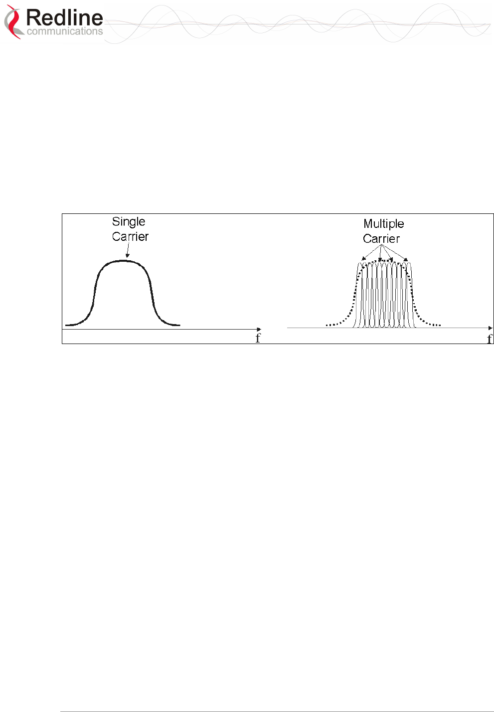
RedMAX™
Base Station
User Manual
Doc. #70-00058-01-01 Proprietary Redline Communications © 2007 July 13, 2007
Page 93 of 119
signal reflections arrive slightly later than the primary signal. The result can be
destructive interference that can essentially null out the primary signal or overlap the
original signal such that it cannot be decoded. Multi-path interference is a problem with
long-range links where reflections off the ground, snow, and water frequently interfere
with the primary signal. It is also a problem in urban environments where the signal
reflects off buildings, trees, and roads.
OFDM breaks up the transmit signal into many smaller signals. For example, instead of
one single carrier carrying 70 Mbps of data (wireless interface rate), there are 192
separate carriers, each carrying about 364 Kbps of data (in the case of the Redline
product) in a 14 MHz bandwidth. If selective fading degrades one or two carriers, the
impact is minimal since the information is spread across the remaining carriers.
Figure 36: Op Notes: OFDM Multiple Carriers
One key aspect of OFDM implementation is that the individual carriers overlap
significantly to preserve overall bandwidth. Normally, overlapping signals would
interfere with each other, however, through special signal processing, the carriers in an
OFDM waveform are orthogonal to each other.
Multipath interference may cause individual narrowband channels to be altogether lost.
This problem is addressed in the Redline implementation in three ways:
1. Equalizing the received signal based on an estimate of the channel fading conditions
(restoring the faded sub-channels).
2. Interleaving the data before modulation onto the individual sub-channels (so that
adjacent data symbols do not necessarily end up on adjacent sub-channels, and thus
deep fades do not impair large chunks of the signal).
3. Convolutional encoding of the input data introduces correlations between signal
samples that are echoed on sub-channels occurring in separate parts of the spectrum.
This allows the receiver to infer the values of the signal that were transmitted on
fatally faded sub-carriers. The key advantage of multiple carriers is that the signal is
more robust to multipath disturbance, as described below.
OFDM equalization and coding techniques cannot overcome all forms of sharp,
multipath-related fading. For additional robustness, the OFDM implementation uses a
guard interval between each of the sub-channels. This guard interval is filled with
redundant data taken from the end of the same channel symbol and repeated at the
beginning of each channel symbol. Multipath echoes from each individual sub-channel
overlap the guard interval, rather than overlapping data in other symbols. Used in

RedMAX™
Base Station
User Manual
Doc. #70-00058-01-01 Proprietary Redline Communications © 2007 July 13, 2007
Page 94 of 119
conjunction with adaptive equalization, coding, and modulation, use of the guard interval
provides reliable operation in a wide class of non line-of-sight environments.
6.4.2 Calculating Receive Sensitivity (WiMAX Testing)
Overview
The WiMAX test for receive sensitivity modifies the methodology from 802.16 to allow
results to be obtained easier and faster. The standard Bit Error Rate (BER) of 1x10⁻⁶
remains the benchmark for these calculations. The BER is obtained by measuring Packet
Error Rate (PER), but PER cannot truly be measured (it is a limit) and requires that a test
be performed to estimate the PER value. Larger sample sizes will produce more accurate
values for PER. There is a practical limit to the size of the test sample, and WiMAX has
chosen the number of packets in the sample to enable result that will approximate a BER
lower than 1x10⁻⁶.
Sample Test for Subscriber Receive Sensitivity
1. Connect packet generator to the base station-to-subscriber link and then configure
packet generator to send 50,000 Ethernet packets with payload of 288 Bytes (i.e.,
total Ethernet packet size is 288 + 18 = 306 Bytes). Payload should not be chosen by
the packet generator, but must be filled with the pattern defined in the WiMAX
standard. The packets should be sent at a rate to fill at least 80% of the downlink
(DL) frame.
2. Count the number of packets received. If less than 97 packets are lost, it can be
stated with 95% confidence that the BER is 1x10⁻⁶ or lower.
3. Repeat the test by sending 20,000 Ethernet packets with payload of 864 Bytes. If less
than 118 packets are lost, it can be stated with 95% confidence that the BER is 1x10-
6 or lower.
4. You repeat the test by sending 10,000 Ethernet packets with payload of 1488 Bytes.
If less than 100 packets are lost, it can be stated with 95% confidence that the BER is
1x10⁻⁶ or lower.
5. Receiver sensitivity is defined as the lowest RSSI value tested where samples for all
three packet sizes did not exceed the maximum number of lost packets. The 95%
confidence level indicates that if the test is repeated multiple times, you will obtain
passing results 95 times out of 100.
Refer to the following table for a summary of the test parameters.

RedMAX™
Base Station
User Manual
Doc. #70-00058-01-01 Proprietary Redline Communications © 2007 July 13, 2007
Page 95 of 119
Table 36: Op Notes: Receive Sensitivity Tests
Packet Payload
Size
Total Number of
Packets Sent
Max. Number of
Packets Lost
Equivalent BER
(95% Confidence)
288 50,000 97 1x10⁻⁶
300,000 100 1x10⁻⁹
864 20,000 118 1x10⁻⁶
100,000 55 1x10⁻⁹
1,488 10,000 100 1x10⁻⁶
60,000 57 1x10⁻⁹
6.4.3 General Interference
Redline has introduced several techniques into its products to mitigate interference
issues:
1. OFDM: multiple carriers using both time and frequency diversity to provide high
tolerance to co-channel and adjacent channel interference, remove ISI due to
multipath and recover data from carriers falling in regions of deep channel fades.
2. Multiple channels (twenty-eight non-overlapping at 3.5 MHz) for diversity and
interference mitigation.
3. Adaptive modulation using six transmission rates to suit varying link conditions.
4. Adaptive encoding is heavily coded to substantially increase robustness. State of the
art FEC using Convolutional-coding gives the base station superior frequency
selective fading mitigation capability.
5. Narrow beam antennas with high side lobe and backlobe isolation and very low
VSWR.
6. Antenna cross-polarization enabling equipment co-location as well as effective
frequency planning.
7. High receiver dynamic range to address dynamic interference.
8. State of the art filtering at the RF, IF and baseband levels to reduce interference.
9. Choice of non-adaptive modulation to provide stable burst rate during periods of
rapid interference variations on the link.
RedMAX™
Base Station
User Manual
Doc. #70-00058-01-01 Proprietary Redline Communications © 2007 July 13, 2007
Page 96 of 119
Chapter
7
7
7
T
Tr
ro
ou
ub
bl
le
es
sh
ho
oo
ot
ti
in
ng
g
7.1 Secondary Management Channel (SMC)
The SMC has a higher priority than data in downlink, but the maximum rate is limited to
512 Kb/s in normal operation. During SMC maintenance intervals, the rate is unlimited to
allow faster FTP transfers over SMC. The SMC maintenance interval can be enabled by
the Redline Management Suite (RMS). In uplink the first 32 Kbps of the SMC traffic has
a higher priority than data, and the remaining SMC traffic has lower priority.
7.2 Time Synchronization
When operating two or more collocated base stations (BSs), transmitter operations
MUST use synchronization to minimize inter-sector interference. Refer to the RedMAX
Base Station Installation Guidelines for complete details.
7.3 Factory Default Settings
The table lists some important factory default settings for the base station terminal.
Table 37: Troubleshooting - Factory Default Settings
Setting Sub Field Value
Ethernet Interface Management Via Data port (integrated)
Management Interface IP Address 192.168.101.3
Wireless Interface RF Frequency 3448000 KHz*
Wireless Interface RF Reference RSS 69 dBm
Wireless Interface RF Tx Power 0 db
Wireless Interface PHY Channel size 3.5 MHz
Wireless Interface PHY Guard Interval 1/4
Wireless Interface MAC Adaptive DL/UL Ratio Disabled
Wireless Interface MAC Cell Range Km 5
Wireless Interface MAC DL Ratio 54
Wireless Interface MAC Frame Duration 10 msec
Wireless Interface MAC Synchronization Mode No sync
Admin Login Login
Password
admin
admin
Guest login Login
Password
guest
guest
Debug Login Login
Password
debug
redline
*Based on 3-4-3.6 GHz radio.
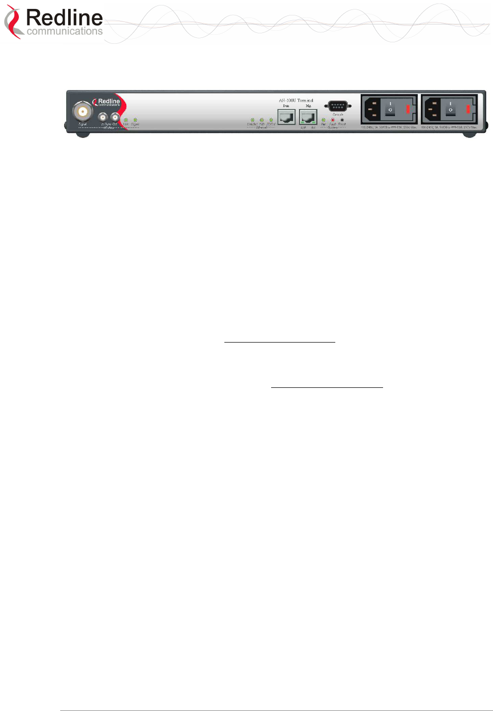
RedMAX™
Base Station
User Manual
Doc. #70-00058-01-01 Proprietary Redline Communications © 2007 July 13, 2007
Page 97 of 119
7.4 Front Panel Diagnostics
Figure 37: Diagnostics: Base Station Front Panel View
7.4.1 System LEDs
The front panel of the terminal includes a number of LEDs to monitor operation of the
system and assist troubleshooting. Refer to section 3: Physical Description on page 25.
7.4.2 Console Port
The front panel includes the Console port. Use the CLI commands to interrogate the base
station status and program most system settings.
7.4.3 System Reset Switch
Throughout this section, reference is made to the reset switch, which is a micro-switch
recessed in the front panel in the system block. Use a small narrow object, such as a
paper clip, to access the switch.
Depressing the reset switch for less than five seconds activates a short-reset. This is
equivalent to turning the terminal off and on. Statistical values are reset. The selected
system software image is loaded.
Depressing the front panel reset switch for more than five seconds activates a long-reset.
A long-reset reloads the factory defaults for the IP Address, IP subnet mask, and
password and then resets the system. Statistical values are reset. The selected system
software image is loaded.
7.5 Recovering a Lost IP address
Use a DB-9 serial cable to access the base station serial console. The configuration of the
serial port should be 57,600 bps, no parity, 8 data bits, 1 stop bit. Once connected, type in
the command ifShow and read the value of inet under the idt interface.
7.6 Detecting Channel Interference at Startup
Following a power-cycle or reboot, the base station monitors the RF Channel to detect
interference on the uplink channel. The transceiver is set to receive mode and the PHY is
programmed to receive a long preamble from a WiMAX base station. If no preamble is
detected during the one-second interval, the channel is considered free of interference
from other WiMAX equipment.
If a long preamble is received, the base station continues to monitors the channel for an
additional three seconds. If an 802.16d DL-Map is received, the following message will
be entered into the event log:
WARNING: RF Channel Conflict with [BS Id]
This message in the event log indicates that another base station has been detected using
the following RF-PHY characteristics:

RedMAX™
Base Station
User Manual
Doc. #70-00058-01-01 Proprietary Redline Communications © 2007 July 13, 2007
Page 98 of 119
- Same DL channel frequency as the UL channel frequency of this SC
- Same Cyclic Prefix
- Same channel size (i.e., 7 MHz)
If a long preamble was received, but no DL-Map was detected, the following message
will be entered into the event log:
WARNING: Unknown Interference was detected on the UL channel
This second message does not necessarily indicate interference from another base station,
and may be the result of cross-interference from subscribe stations.
7.7 Re-Ranging Log Message
The log message 're-ranging' is recorded by the base station when a registered subscriber
initiates a network entry sequence.
There are two common reasons for this event:
1. When network entry is complete, the subscriber retains its 'registered' state by
sending data traffic to the base station. When there is no data traffic, the SU-O sends
only periodic ranging requests each 25 seconds. Under no-traffic conditions, it may
take the base station more than 25 seconds to declare a subscriber unavailable and
mark it as de-registered. During the same 25 second period, the subscriber may
declare the base station to be unavailable (i.e., due to poor link conditions) and begin
attempts to re-register. In this scenario, the subscriber is attempting to re-register
before the base station has declared the subscriber to be failed.
2. This condition may also result from a loss of connectivity between a subscriber and
the DHCP server or TOD server. When remote management is enabled on the
subscriber (managedSS=1), the subscriber must communicate with the DHCP server
and the ToD server specified in the obtained lease. If communication cannot be
established within two minutes, the subscriber will reset and repeat the attempt.
7.8 Troubleshooting the Web Interface
These troubleshooting steps assume that the status LEDs on the front panel of the
terminal indicates normal function.
1. Open a Web browser and attempt to login to the base station terminal. If the terminal
does not respond by displaying the login dialog box, check that the correct IP address
is being used. The factory default address is listed in the Troubleshooting section.
The IP address may have been changed during installation. For correct operation the
host computer and the terminal must appear to be on the same subnet. Ensure that the
IP address for the PC is set to the same subnet as the terminal. For example, the IP
address should only differ in the last octet (i.e., 192.168.101.X).
2. The next test is to verify the IP address is reachable from the computer. Use the ping
command to test the connection between the terminal and host computer. The system
always responds to ping frames less that 577 bytes in length.
If the ping test is successful the host computer was able to send and receive packets.
The problem may be with the Internet browser or related settings on the host
computer. Re-boot the host computer to try to resolve the problem.
RedMAX™
Base Station
User Manual
Doc. #70-00058-01-01 Proprietary Redline Communications © 2007 July 13, 2007
Page 99 of 119
If the ping is not successful, the IP address may be incorrect, or a duplicate address
may exist.
3. If the current address of the terminal cannot be determined, it is recommended to
perform a long-reset. Performing a long-reset restores the terminal IP address and IP
Subnet Mask to the factory default values. Note that this operation may discard some
custom settings.
Table 38: Troubleshooting - Web Interface Diagnostics
Symptom Possible Problem Solution
Incorrect IP address
and/or Subnet Mask.
Perform a ping test from the host computer
command line. If the ping test is unsuccessful,
then the problem is with the IP address. Perform
a long-reset to restore the default address.
Problems with host
computer, or terminal.
If the ping is successful, reboot of the base
station and/or host computer.
Login
screen
cannot be
accessed.
Host PC ARP table is
incorrectly configured.
Run 'arp -d' whenever connecting to a different
base station terminal. Check that the subnet
mask for the host PC matches the subnet mask
of the terminal. Check that the host PC address
is in the same subnet.
7.9 Replacing the System Fuse
Important: Always completely remove power from the base station before performing
any maintenance on the terminal or modem.
Warning to service personnel:
Caution for all AC and DC models – Double Pole/Neutral fusing.
To replace fuse:
1. Disconnect power from the terminal.
2. Pry off the black plastic cover located on the back panel beside the power switch and
extract the red fuse holder.
3. Use an approved tool to remove the glass-cased fuses from the holder.
Be certain to replace the fuse(s) into the lower half of the holder, as shown in the
diagram below. The fuse holder holds two fuses, both of which are active. Be certain
to use fuses of the same type and rating.
4. Replace the fuse holder in the system terminal and secure.
5. Restore power to the base station.
Figure 38: Diagnostics: Base Station Power Supply Fuse Holder
RedMAX™
Base Station
User Manual
Doc. #70-00058-01-01 Proprietary Redline Communications © 2007 July 13, 2007
Page 100 of 119
7.10 RF Troubleshooting
The terminal monitors the status of the outdoor modem unit and reports any fault
conditions in the system event log. The following table lists the general fault conditions
reported by the terminal.
Table 39: Troubleshooting - RF Error Diagnostics
Error Type Description
IF PLL Unlocked The PLL (Phase Locked Loop) section within the terminal
experienced an error. The System Fault LED may light. Try
resetting the unit.
Communication Error
Over IF Cable
Communication between the terminal and the modem failed.
Check the IF cable and connectors.
Outdoor Unit
Temperature is too
High. Air Interface
Disabled for 15 Minutes
The internal temperature of the modem is above 82C
(180°F). The modem shuts down to allow cooling.
Outdoor Unit Power
Supply Error
Displays a fault in the modem power supply. This error could
be due to a problem with the internal power supply or with
the power source from the terminal. If the 'Low DC Voltage
At Radio' error is also indicated, (see below) check the IF
cable and connectors. If the 'Low DC Voltage At Radio' error
is not indicated, the modem requires servicing.
Outdoor Unit 24V Error The DC voltage at the modem (carried by the IF cable from
the terminal) is lower than the required 24 VDC. Check the
IF cable and connectors. The minimum required voltage for
operation is 12 VDC.
Air Interface Disabled The radio is disabled.
Cable Compensation
Failed
The measured IF cable compensation is out of specification.
Invalid Radio The attached radio is not compatible with this
terminal/configuration.
Outdoor Unit 3.3V Error The modem internal power supply is lower than the required
3.3 VDC.
7.11 System Log Messages
Table 40: Troubleshooting - Event Log Messages
Log Message Description
Access Address : 0x%08x This message is displayed only after a watchdog reset
occurs. It provides information about the software
exception that caused the watchdog.
Air Interface is Disabled The RF interface has been disabled by the user.
Air Interface is Enabled The RF interface has been enabled by the user.
Another Upgrade operation
is currently running. Skip
SNMP[CLI,WEB] upgrade
The user has tried to initiate an upgrade while another
upgrade is already in progress. The command has been
ignored.

RedMAX™
Base Station
User Manual
Doc. #70-00058-01-01 Proprietary Redline Communications © 2007 July 13, 2007
Page 101 of 119
Table 40: Troubleshooting - Event Log Messages
Log Message Description
Another Upgrade operation
is currently running. Skip
SNMP[CLI,WEB]
synchronization
The user has tried to synchronize the active and
alternate images while a software upgrade is in
progress. The command has been ignored.
Another Upgrade operation
is currently running. Skip
SNMP[CLI,WEB] backup
The user has tried to backup the active image to the
alternate while a software upgrade is in progress. The
command has been ignored.
Another Upgrade operation
is currently running. Skip
SNMP[CLI,WEB] restore
The user has tried to apply a configuration file to either
the active or alternate images while a software upgrade
is in progress. The command has been ignored.
Another Upgrade operation
is currently running. Skip
switchover
The user has tried to switch software versions while an
upgrade is in progress. The command has been
ignored.
Backup Detected This base station is configured as Master, and it has
detected the presence of a Backup Slave
Backup Function Activated This base station is configured as a Backup Slave, and
has been successfully activated
Cable Compensation Ok.
Value = [v]
The attenuation of the IF cable is within operating
parameters.
Cause Register: 0x%08x This message is displayed only after a watchdog reset
occurs. It provides information about the software
exception that caused the watchdog.
CRITICAL: Cable
Compensation Failed
The attenuation of the IF cable to the ODU is too high.
CRITICAL: IF Cable
Disconnected
The IF cable between the base station IDU and ODU
has been disconnected.
CRITICAL: IF PLL Error The IF chain has encountered a PLL error.
Communication with the ODU has been interrupted.
CRITICAL: LO[X] Error There has been a hardware problem with Local
Oscillator [X].
CRITICAL: ODU
Temperature is too High
The operating temperature of the base station ODU is
too high to continue operation. The IDU will temporarily
suspend operation to avoid damage.
CRITICAL: Radio
Reference Frequency Error
There has been a hardware problem with the
synchronization of the ODU’s reference frequency.
CRITICAL: Rx IF PLL Error The IF chain has encountered a PLL error.
Communication with the ODU has been interrupted.
Eep Configuration
checksum error.
Parameters are reset to
factory defaults. Force WD
reset...
Self explanatory
Error address: 0x%08x,
Error ID: 0x%04x
This message is displayed only after a watchdog reset
occurs. It provides information about the software
exception that caused the watchdog.
Error when reading from i2c
memory
Hardware failure. There was an error while reading
some configuration data.

RedMAX™
Base Station
User Manual
Doc. #70-00058-01-01 Proprietary Redline Communications © 2007 July 13, 2007
Page 102 of 119
Table 40: Troubleshooting - Event Log Messages
Log Message Description
Error when writing to i2c
memory
Hardware failure. There was an error while writing some
configuration data.
Event log cleared by user Self explanatory
Exception Program
Counter: 0x%08x
This message is displayed only after a watchdog reset
occurs. It provides information about the software
exception that caused the watchdog.
Fp Status Register: 0x%08x This message is displayed only after a watchdog reset
occurs. It provides information about the software
exception that caused the watchdog.
GPS Detected An external GPS clock source has been properly
detected.
GPS is not Detected.
Waiting for GPS...
An external GPS clock source has not been detected.
The RF interface will not be started until this problem is
resolved.
Invalid Radio Type The radio connected to the base station is not
compatible.
Long Reset The base station has been reset to factory defaults by
the user.
Master Detected A slave has detected the presence of a master.
Master Function Activated This base station is configured as Master, and it has
successfully activated.
Master is Not Detected A slave has failed to detect the clock signal of a master
Master or GPS must be
connected. Waiting...
A backup slave has not detected the presence of a
Master or GPS clock source. It will wait for one before
activating its RF interface.
Master with GPS Function
Activated
This base station is configured as Master, and has been
successfully activated.
NOTICE: Watchdog is
Disabled
A jumper installed during factory burn-in was not
properly removed before shipping.
Ntp client: Invalid address The IP address of SNTP server cannot be resolved
Ntp client: Server Unsync The received timestamp is 0, or the SNTP server
suggests it is not synchronized
Ntp client: Timeout The SNTP server does not reply to SNTP requests
Ntp client: Version
unsupported
SNTP server version number is greater than 3
Other Backup Detected.
Waiting...
This base station is configured as a Backup Slave, but
another backup slave has been detected.
Other Master Detected.
Waiting...
The base station is configured to act as a Master, but it
has detected the presence of another Master.
P1 Watchdog Reset The P1 processor has encountered an exception, and
has prompted a reboot of the base station
P2 Watchdog Reset The P2 processor has encountered an exception, and
has prompted a reboot of the base station
P2-Task: %#x \"%s\ This message is displayed only after a watchdog reset
occurs. It provides information about the software
exception that caused the watchdog.

RedMAX™
Base Station
User Manual
Doc. #70-00058-01-01 Proprietary Redline Communications © 2007 July 13, 2007
Page 103 of 119
Table 40: Troubleshooting - Event Log Messages
Log Message Description
Parameters are reset to
factory defaults
This message appears after the user has initiated a
long-reset to factory defaults
Power Supply [X] is On Where X is either A or B. This signifies that the relevant
power supply has been detected and is properly
supplying power to the base station
Radio Type [XX]:
TBXXXXFX
This message is simply a confirmation of the type of
radio connected to the IDU. It should match with the
radio type printed on the ODU’s sticker.
RedMax base station Ver.
X.X.X started
System startup message.
Reference Clock
Calibration Done
The reference clock calibration procedure initiated by
the user has been completed.
Reference Clock
Calibration Failed
The reference clock calibration procedure initiated by
the user has failed.
Restore configuration into
active image
The user-provided configuration file has been applied to
the active image
Restore configuration into
alternate image
The user-provided configuration file has been applied to
the alternate (non-active) image
RF capabilities are
changed. Check RF and
PHY parameters and
activate again the RF
interface
Self explanatory
Status Register: 0x%08x This message is displayed only after a watchdog reset
occurs. It provides information about the software
exception that caused the watchdog.
Synchronization Failed.
Waiting for Synchronization
Signal...
A base station configured as Slave has detected the
Master on reboot, but synchronization failed. It will wait
and try again.
Synchronization Lost A slave has previously synchronized with a Master, but
since lost the signal and drifted out of phase.
Synchronization of alternate
completed successfully
Software image and configuration have been applied to
the alternate image, overwriting its previous contents.
Synchronization of
configurations not possible
The synchronization of software and configuration from
the active image to the alternate has failed.
Synchronization Ok Synchronization with a Master or Backup Slave was
successful.
Synchronization Signal not
Detected. Waiting...
A base station configured as Slave cannot detect the
synchronization Master.
Synchronization with
Backup Failed
This base station is configured as Master. It has recently
rebooted, detected the presence of a Backup Slave, but
it has failed to resume control of the base station’s
clock.
Synchronization with
Backup Ok
This base station is configured as Master. It has recently
rebooted, detected the presence of a Backup Slave, and
successfully resumed control of the base station’s clock.
Synchronization with GPS
is Lost
Synchronization with a previously detected external
clock source has been lost

RedMAX™
Base Station
User Manual
Doc. #70-00058-01-01 Proprietary Redline Communications © 2007 July 13, 2007
Page 104 of 119
Table 40: Troubleshooting - Event Log Messages
Log Message Description
Synchronization with GPS
Ok
Synchronization with an external GPS clock has been
successfully completed.
Synchronization with
Master is Lost
A backup slave has previously detected the presence of
a master clock signal, and synchronized. It has since
lost this signal.
Synchronization with
Master Ok
A slave has successfully synchronized with a master’s
clock signal
Synchronization Signal
Detected
A Slave has detected the clock signal of a Master.
Synchronization Signal not
Detected
A slave has previously synchronized with a Master, but
has since lost the signal.
WARNING: Clock Offset
Close to End of Scale
The reference clock calibration procedure initiated by
the user has been completed, but the clock offset is at
the boundaries of the base station’s capabilities
WARNING: DL aggregated
Guaranteed Rate exceeds
Capacity
The aggregate guaranteed minimum rates configured
for service flows using RTPS and UGS scheduling
exceeds the downlink capacity of the sector.
WARNING: Indoor Unit
Temperature > 65 Celsius
The base station indoor unit has exceeded the
recommended operating temperature.
WARNING: ODU
Temperature is [c] Celsius
The operating temperature of the base station ODU is
nearing the limit of its operating temperature. No action
is taken.
WARNING: Power Supply
[X] is Off
Where X is either A or B. This signifies that the relevant
power supply has been detected, but it is not supplying
power to the base station.
WARNING: UL aggregated
Guaranteed Rate exceeds
Capacity
The aggregate guaranteed minimum rates configured
for service flows using RTPS and UGS scheduling
exceeds the uplink capacity of the sector.
WRONG CRC over I2C The stored interface configuration data has failed
integrity check.
WARNING: Unknown
Interference was detected
on the UL channel
During startup, a long preamble was received but no
DL-Map was detected the UL channel.
See section 7.6: Detecting Channel Interference at
Startup on page 97.
WARNING: RF Channel
Conflict with [BS Id]
During startup, a long preamble and DL-Map were both
detected on the UL channel. See section 7.6: Detecting
Channel Interference at Startup on page 97.

RedMAX™
Base Station
User Manual
Doc. #70-00058-01-01 Proprietary Redline Communications © 2007 July 13, 2007
Page 105 of 119
Chapter
8
8
8
A
Ap
pp
pe
en
nd
di
ic
ce
es
s
8.1 System Technical Specifications
Table 41: Specifications - RedMAX Base Station
System Capability: LOS, Optical LOS, Non LOS
Cell-based Point-to-Multipoint
RF Band: 3.400-3.600 GHz (FWA Band) TDD
3.600-3.800 GHz (FWA Band) TDD
3.400-3.600 GHz (FWA Band) HD-FDD
(Operation is dependant on license/regulatory domain)
Duplex Technique: TDD (time division duplex)
Channel Size: 3.5, 7 MHz
RF Dynamic Range: > 40 dB
Spectral Efficiency: Up to 5 bps/Hz (over the air), up to 3 bps/Hz (net)
Over The Air Rate: Up to 17.5 Mbps Uncoded Rate @ 3.5 MHz channel
Up to 35 Mbps Uncoded Rate @ 7 MHz channel
Data Rate: Up to 10.8 Mbps Max. Ethernet Rate @ 3.5 MHz channel
1
Up to 23 Mbps Max. Ethernet Rate @ 7 MHz channel
1
Latency: 6-18 ms (based on channel size & frame duration)
Maximum Tx Power: +23 dBm (region specific)
Rx Sensitivity: Better than -93 dBm @ BPSK 1/2
(1x10e-6 BER / 3.5 MHz channel)
IF Cable: Maximum length 68 m (225 feet) using only the following Redline
recommended high-grade cable:
Times Fiber cable (part number T58SC85T-VB)
Multiplexed IF, Tx/Rx, AGC, ATPC, DC power
Network Attributes: Transparent bridge, DHCP client pass-through
802.1Q VLAN, 802.1p network traffic prioritization
Modulation/Coding Rates: Modulation: BPSK, QPSK, 16 QAM, 64 QAM
Coding: 1/2, 2/3, 3/4
Over the Air Encryption: DES (traffic)
MAC: Cell-based PMP deployment
64 subscribers/sector
802.16-2004 compliant PMP
802.16-2004 packet convergence sub-layer mode
QoS (delay, CIR/PIR)
Scheduled Services (rtPS, BE)
TDMA Access

RedMAX™
Base Station
User Manual
Doc. #70-00058-01-01 Proprietary Redline Communications © 2007 July 13, 2007
Page 106 of 119
Table 41: Specifications - RedMAX Base Station
Range: 20 km (13 miles) LOS
3 km (2 miles) non LOS
Wireless Transmission: 256 FFT OFDM (orthogonal frequency division multiplexing)
Network Connections: RJ-45 (10/100 Ethernet)
System Configuration: HTTP (Web), SNMP, FTP (software updates)
CLI via Local Console (RS-232) only
Network Management: SNMP, standard and proprietary MIBs
Full management by RedMAX Management Suite
Power Requirements: Auto-sensing 90-264 VAC (47-63 Hz)
Auto-sensing 21 - 60 VDC, 75 W maximum
Optional dual AC or dual DC power supply
(dual cord with automatic failover)
Standards: IEEE: 802.3, 802.3x, 802.1Q, 802.1p.,802.16-2004
ITUT: G.711, 723, 726, 729, 168 (VoIP codec)
Compliance: EMC: EN 301 489-1, EN 301 489-4, (EN 55022/CISPR 22)
IEC 61000-4-5 class 3 (2 KV), ITU-T K.21
ESD as per EN 61000-4-2.
Radiated Immunity as per EN-1000-4-3.
EFT as per EN 61000-4-4
Surge as per EN 61000-4-5
Conducted Immunity as per EN 61000-4-6
Dips & interrupts (AC versions only) as per EN 61000-4-11
Flickers and harmonics (AC versions only) comply to
EN 61000-3-2, EN 61000-3-3
RF: EN 302 326, Industry Canada: RSS-192
Safety: IEC 60950-1, UL 60950-1
Operating Temperature: IDU: 0 C to 40 C
IDU Short-term: 0 C to 55 C for up to 5 hours
ODU: -40 C to 60 C
Wind Loading: Antenna: 220 Km/hr (137 mph)
Dimensions: 431.8 x 304.8 x 44.45 mm (17 x 12 x 1.75 in)
Weight: 2.5 Kg (5.5 lb)
Humidity: Up to 90% non-condensing
1 Actual Ethernet data throughput is dependent on channel size, protocols, packet size, burst
rate, transmission latency, and link distance.
RedMAX™
Base Station
User Manual
Doc. #70-00058-01-01 Proprietary Redline Communications © 2007 July 13, 2007
Page 107 of 119
8.2 Radio Types
The following radio types are supported:
Table 42: Specs - Radios with 3.5 MHz and 7 MHz Channels
Radio Type: TB3436F7 TB3638F7
Channelization: 3.5 MHz, 7 MHz 3.5 MHz, 7 MHz
Operation: TDD, HD-FDD TDD
Frequency: 3.4 - 3.6 GHz 3.6 - 3.8 GHz
Tx Power: 23 dBm 23 dBm
Tx Power Tolerance: +/- 2 dBm +/- 2 dBm
Maximum Power Consumption: 24 V, 1.5 A 24 V, 1.5 A
8.3 Receive Sensitivity
The following table lists the sensitivity levels for different modulation and coding levels.
Table 43: Specs - Base Station Receive Sensitivity
Modulation Coding 3.5 MHz 7 MHz
BPSK 1/2 -94 -91
1/2 -93 -90
QPSK 3/4 -92 -89
1/2 -89 -86
16 QAM 3/4 -86 -83
2/3 -82 -79
64 QAM 3/4 -77 -74
8.4 Throughput versus Distance
he following table represents the expected decrease in throughput (Kbps) associated
Receive Sensitivity with the distance between the base station and subscriber.
Table 44: Expected Throughput Decrease Over Distance (Kb/s)
Distance (Km)
Channel Size 5 10 15 20 25 30 35 40
3.5 MHz 0 86 86 173 173 260 260 346
7 MHz 86 173 260 346 346 432 518 605
1. Line-of-sight links operating at 64 QAM 3/4 with 10 ms frame duration. Throughput decrease is
x2 when using 5 ms frame duration.
2. Typical deployed cell radius is <10 Km. Distances of >10 Km are quoted for backhaul.
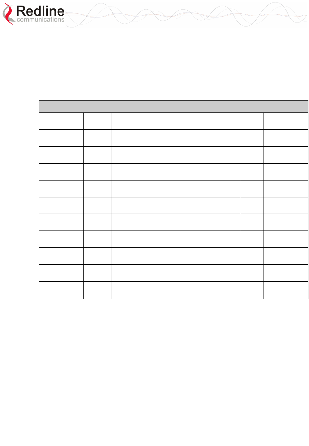
RedMAX™
Base Station
User Manual
Doc. #70-00058-01-01 Proprietary Redline Communications © 2007 July 13, 2007
Page 108 of 119
8.5 FCC Certified Antennas
This device has been designed to operate with the antennas listed below, having a
maximum peak gain of 24 dB. The Max. Tx Power Setting in the GUI listed below for
each antenna will limit the EIRP at any time to 1W/1MHz (30 dBm). Antennas not
included in this list or having a peak gain greater than 24 dB are strictly prohibited for
use with this device. The required antenna impedance is 50 ohms.
Table 45: Spec. - FCC Certified Antennas: 5.4 GHz Operation
Redline PN
A
nt. Gain
(dBi)
Antenna Description App. GUI Max. Tx
Power Setting
A2408MTF 24 Antenna: 2 foot, 8 degree, 24 dBi flat panel
antenna.
PTP -5
A2014ARF 20 Antenna: 1 foot, 13.5 degree, 20 dBi flat
panel antenna.
PTP -1
PA1760EAS 17 Sector Antenna: 60 degree, 17 dBi, vertical
polarization.
PMP 2
PA1660EASH 16 Sector Antenna: 60 degree, 16 dBi, horizontal
polarization.
PMP 3
PA1690EAS 16 Sector Antenna: 90 degree, 16 dBi, vertical
polarization.
PMP 3
PA1590EASH 15 Sector Antenna: 90 degree, 15 dBi, horizontal
polarization.
PMP 4
A1490MTS 14.5 Sector Antenna: 90 degree, 14.5 dBi, vertical
polarization
PMP 4.5
PA14120EAS 14 Sector Antenna: 120 degree, 14 dBi,
horizontal polarization.
PMP 5
PA14120EASH 14 Sector Antenna: 120 degree, 14 dBi,
horizontal polarization.
PMP 5
A11360EAO 11 Sector Antenna: 360 degree, 11.0 dBi.
PMP 8
Note: The RF output power and selection must be professionally programmed
and installed by the manufacturer or a trained professional installer.
RedMAX™
Base Station
User Manual
Doc. #70-00058-01-01 Proprietary Redline Communications © 2007 July 13, 2007
Page 109 of 119
8.6 DC Power Connections
This section provides important instructions for connecting to a DC power source.
The DC power supply (optional) is rated for operation from 21 to 60 volts DC.
Warning to service personnel:
Caution for all AC and DC models – Double Pole/Neutral fusing.
Power is supplied to the terminal using a fused power entry module. All DC terminals are
shipped with a one-meter power cord assembly, consisting of the power entry module’s
mating dual pin polarized female plug pre-crimped with 18 AWG blue and black
insulated wires. If the wiring needs to be extended a minimum of 18 AWG wire must be
used.
The DC power input is floating (+Ve and -Ve not connected to chassis), allowing positive
(minus to ground), negative (plus to ground), and floating power connections as required.
Refer to table below for connection details.
If the terminal does not power on, it is possible that the blue and black wires are
connected incorrectly resulting in a reversal of polarity. In this event, the diode protection
prevents permanent damage to the power supply. Reverse the power connections and
verify that the terminal powers up properly.
Table 46: DC Power Supply Cable Connections
Wire Color Negative DC Power
(-21 to –60 VDC)
Positive DC Power
(+21 to +60 VDC)
Blue Negative power Power Return
Black Power Return Positive Power
Schematics
Warning to service personnel:
DC units are not equipped with power switches and activate
immediately when connected to a power source.

RedMAX™
Base Station
User Manual
Doc. #70-00058-01-01 Proprietary Redline Communications © 2007 July 13, 2007
Page 110 of 119
8.7 Glossary
Term Acronym Definition
Active Service
Flow
- An Admitted Service Flow that is active and available for
packet transmission.
Address
Resolution
Protocol
ARP An IETF protocol for converting network addresses to 48-bit
Ethernet addresses.
Admitted
Service Flow
- Service Flow is registered, but not active.
RedMAX Base
Station System
The base station terminal, modem, and antenna.
RedMAX Base
Station Terminal
The base station indoor unit.
Antenna Gain - The measure of antenna performance relative to a theoretical
antenna called an isotropic antenna.
Base Station BS The RedMAX base station terminal configured as central
equipment (also referred to as a base station).
Beamwidth - The angle of signal coverage provided by an antenna.
Best Effort
Service
BE BE service provides efficient service to best effort traffic. In
order for this service to work correctly, the
Request/Transmission Policy setting should be such that the
Subscriber is allowed to use contention request opportunities.
This results in the Subscriber using contention request
opportunities as well as unicast request opportunities and
unsolicited Data Grant Burst Types. All other bits of the
Request/Transmission Policy are irrelevant to the fundamental
operation of this scheduling service and should be set
according to network policy. The key service elements are the
Minimum Reserved Traffic Rate, the Maximum Sustained
Traffic Rate, and the Traffic Priority.
Binary Phase
Shift Keying
BPSK BPSK is a digital modulation technique. This type of
modulation is less efficient than similar modulation techniques
such as QPSK and 64 QAM, but is less susceptible to noise.
Bps Bps A unit of measurement for data is transfer.
Broadband
Fixed Wireless
BFW High-speed wireless installation where the equipment is not
mobile.
Broadcast
Addresses
- A predefined destination address that denotes the set of all
data network service access points.
Burst - A group of protocol data units (PDUs) transmitted over the
wireless link using the same profile.
Burst profile - Enter of settings that describe the uplink or downlink
transmission properties associated with an Interval Usage
Code. Each profile contains settings such as modulation type,
forward error correction type, preamble length, guard times,
etc.

RedMAX™
Base Station
User Manual
Doc. #70-00058-01-01 Proprietary Redline Communications © 2007 July 13, 2007
Page 111 of 119
Term Acronym Definition
CEPT The European Conference of Postal and Telecommunications
Administrations (CEPT) established in 1959. CEPT activities
included co-operation on commercial, operational, regulatory
and technical standardization issues.
Channel - A communications path wide enough to permit a single RF
transmission.
CIR CIR Minimum Reserved Traffic Rate (see QoS)
CINR CINR CINR is the ratio of Carrier/(Interference + Noise).
Class of Service - Each Class of Service can be defined by a set of QoS
settings.
Classifier - A set of criteria used for packet filtering which map each
packet to the corresponding Service Flow (i.e., IP or MAC
address).
Committed
Information Rate
CIR The minimum guaranteed bandwidth for a connection.
Concatenation - The act of combining multiple medium access control (MAC)
protocol data units (PDUs) into a single burst.
Connection - A unidirectional mapping between RedMAX base station and
subscriber medium access control (MAC) peers for
transporting service flow’s traffic. A Connection Identifier (CID)
identifies connections.
All traffic is carried on a connection, even for service flows that
implement connectionless protocols, such as Internet Protocol
(IP).
Connection
Identifier
CID A unidirectional, medium access control layer address that
identifies a connection to equivalent peers in the medium
access control layer of the base station and subscriber.
A CID maps to a service flow Identifier (SFID), which defines
the Quality of Service (QoS) settings of the Service Flow
associated with that connection.
Initial Ranging - A well-defined Connection Identifier that is
used by a subscriber during the initial ranging process. This
CID is defined as constant value within the protocol since a
subscriber has no addressing information available until the
initial ranging process is complete.
Transport - unique identifier taken from the Connection
Identifier address space that uniquely identifies the Transport
Connection.
Cyclic Prefix CP Guard interval to resist multipath effect.
Data Link Layer - Layer 2 in the Open System Interconnection (OSI)
architecture; the layer that provides services to transfer data
over the transmission link between open systems.
DB - A ratio expressed in decibels.
dBi - A ratio, measured in decibels, of the effective gain of an
antenna compared to an isotropic antenna.
DBm - Decibels relative to a milliwatt
Directional
Antenna
- An antenna that concentrates transmission power into one
direction.

RedMAX™
Base Station
User Manual
Doc. #70-00058-01-01 Proprietary Redline Communications © 2007 July 13, 2007
Page 112 of 119
Term Acronym Definition
Download
Interval Usage
Code
DIUC An interval usage code specific to a downlink (from RedMAX
base station to subscriber).
Downlink - The direction from the RedMAX base station to the subscriber.
Downlink
Channel
Descriptor
DCD A medium access control layer message that describes the
physical layer characteristics of a downlink channel.
Downlink Map DL-MAP A medium access control layer message that defines a map
with burst start times. DL-MAP is the main message that
defines synchronization of Subscriber. Based on the map
Subscriber read and parse the Downlink information.
Downstream - Flow from base station to subscriber.
Downstream
Classifier
- Assigns packets to downstream service flows.
Dynamic Host
Configuration
Protocol
DHCP An Internet protocol used for assigning network-layer (IP)
addresses dynamically.
Dynamic service - The set of messages and protocols that allow base station
and subscriber to add, modify, or delete the characteristics of
a service flow.
Encryption - For the purposes of privacy, the transformation of data into an
unreadable format until reformatted with a decryption key.
Ethernet - A LAN architecture using a bus or star topology
FCS FCS Frame Check Sequence.
File Transfer
Protocol
FTP (Client and Server): Protocol implementing RFC 959 and
running in NOC-S as Client and BSC as Server for
transferring/replicating configurations files needed by local
DHCPs.
Frame - A structured data sequence of fixed duration used by some
physical layer specifications. A frame may contain both an
uplink sub frame and a downlink sub frame.
Frequency
Agnostic
- Operating independently of the radio frequency selection.
Frequency
Division
Duplexing
FDD A transmission method that separates the transmitting and
receiving channels with a guard band (some amount of
spectrum that acts as a buffer or insulator).
In a framed (burst) FDD system, the uplink and downlink
channels are located on separate frequencies and the
downlink data can be transmitted in bursts. A fixed duration
frame is used for both uplink and downlink transmissions.
Full Duplex - Refers to the transmission of data in two directions
simultaneously (i.e. a telephone)
Gain - The ratio of the output amplitude of a signal to the input
amplitude of a signal. Typically expressed in decibels (dB).
Gateway - A network point that acts as an entrance to another network.
Gigahertz GHz 1,000,000,000 Hz, or 1,000 MHz

RedMAX™
Base Station
User Manual
Doc. #70-00058-01-01 Proprietary Redline Communications © 2007 July 13, 2007
Page 113 of 119
Term Acronym Definition
Grant Per
Connection
GPC A bandwidth allocation method in which grants are allocated to
a specific connection within a subscriber. Note that bandwidth
requests are always made for a connection. A Subscriber can
have multiple connections. In GPC mode, Subscriber request
bandwidth for each connection.
Header Check
Sequence
HCS Header Check Sequence error. This is a CRC error on the
header fields only.
Hertz Hz The international unit for measuring frequency, equivalent to
the number of cycles per second. One megahertz (MHz) is
one million Hertz. One gigahertz (GHz) is one billion Hertz.
Information
Element
IE A component of the downlink or uplink map that defines the
starting address associated with an IUC that identifies a
certain burst profile.
Internet Protocol IP See TCP/IP
Interval Usage
Code
IUC A code identifying a particular burst profile that can be used by
a downlink or uplink transmission interval.
Isotropic - A theoretic construct of an antenna that radiates its signal 360
degrees both vertically and horizontally—a perfect sphere.
Generally used as a reference.
Latency - Delay
Lightweight
Directory
Access Protocol
LDAP Internet protocol described in RFC 2251 and implemented in
NOC-C, NOC-S and SR. It is designed to provide quick
access to directories that contain information locally in
attributes or externally in databases such as SQL. In our
provisioning system LDAP is the engine that replicates,
distributes, searches, reads and writes Subscriber information
(CPE-NAMES, Service Flows).
Line Of Sight LOS A clear direct path between two antennas, with no
obstructions within the first Fresnel zone.
Link Layer
Control
LLC Layer 2 Link Layer Control
Link Budget
Tool
Software application to characterize the range performance for
LOS, OLOS and NLOS conditions for selected system
settings.
Local Area
Network
LAN A data communications network, typically within a building or
campus linking computers, printers and other devices
together.
Local Exchange
Carriers
LEC The traditional local wired phone company.
Management
Connection
- A connection that is established during initial subscriber
registration that is used to transport delay-tolerant medium
access control management messages and even higher layer
management and control messages. Each Subscriber has
three management connections BASIC, PRIMARY and
SECONDARY.
Media Access
Control
MAC A unique number assigned to a network device. It corresponds
to the ISO Network Model Layer 2 data link layer.
Megahertz MHz 1,000,000 Hz
Modulation - Any of several techniques for combining user information with
a transmitter carrier signal.

RedMAX™
Base Station
User Manual
Doc. #70-00058-01-01 Proprietary Redline Communications © 2007 July 13, 2007
Page 114 of 119
Term Acronym Definition
Multicast polling
group
- A group of subscribers that are assigned a multicast address
for the purposes of polling.
Multipath - The RF echoes created from radio signal reflections.
Network Time
Protocol
NTP Protocol for synchronizing a set of network clocks using a set
of distributed clients and servers. It is implemented as Server
on BSC for time synchronization with subscribers and base
stations. Described in IETF RFC 958.
Non Line Of
Sight
NLOS Completely obstructed path between two antennas.
NVRAM Non-volatile RAM memory. Does not lose its data when power
is removed.
Non Real-Time
Priority
nrt-PS The nrt-PS is designed to support non real-time service flows
that require variable size Data Grant Burst Types on a regular
basis, such as high bandwidth FTP. The service offers unicast
polls on a regular basis, which assures that the flow receives
request opportunities even during network congestion. The
RedMAX base station typically polls nrt-PS CIDs on an
interval (periodic or periodic) on the order of one second or
less. The key service elements are Minimum Reserved Traffic
Rate, Maximum Sustained Traffic Rate, Request/Transmission
Policy, and Traffic Priority.
Optical Line Of
Sight
OLOS A clear direct path between two antennas, with obstructions
within the first Fresnel zone.
Orthogonal
Frequency
Division
Multiplexing
OFDM Orthogonal frequency-division multiplexing (OFDM) is a
method of digital modulation in which a signal is split into
several narrowband channels at different frequencies. The
technology was first conceived in the 1960s and 1970s during
research into minimizing interference among channels near
each other in frequency.
In some respects, OFDM is similar to conventional frequency-
division multiplexing (FDM). The difference lies in the way in
which the signals are modulated and demodulated. Priority is
given to minimizing the interference, or crosstalk, among the
channels and symbols comprising the data stream. Less
importance is placed on perfecting individual channels.
Packet - A bundle of data organized in a specific way for transmission.
The three principal elements of a packet include the header,
the text, and the trailer (error detection and correction bits).
Packing - The act of combining multiple service data units (SDU) from a
higher layer into a single medium access control protocol data
unit MPDU.
Physical Layer PHY Provides for the transmission of data through a
communications channel by defining the electrical,
mechanical, and procedural specifications.
Physical slot PS A unit of time, dependent on the physical layer specification,
for allocating bandwidth. PS is designated by 1 OFDM symbol.
PIR - Maximum Sustained Traffic Rate (see QoS)
Privacy key
Management
Protocol
PKM A client/server model between base station and subscriber
that is used to secure distribution of keying material.

RedMAX™
Base Station
User Manual
Doc. #70-00058-01-01 Proprietary Redline Communications © 2007 July 13, 2007
Page 115 of 119
Term Acronym Definition
Protocol Data
Unit
PDU The data unit exchanged between peer entities of the same
protocol layer. On the downward direction, it is the data unit
generated for the next lower layer. On the upward direction, it
is the data unit received from the previous lower layer. MPDU
is the data unit exchanged between peer 802.16 MAC entities.
One MPDU is formed from one or more SDUs.
Provisioned
Service Flow
- A Service Flow that has been provisioned as part of the
Registration process, but has not yet been activated or
admitted. It may still require an authorization exchange with a
policy module or external policy server prior to admission.
Quadrature
Amplitude
Modulation
QAM Quadrature Amplitude Modulation (QAM) is a method of
combining two amplitude-modulated (AM) signals into a single
channel, doubling the effective bandwidth. QAM is used with
pulse amplitude modulation (PAM) in digital systems,
especially in wireless applications.
In a QAM signal, there are two carriers, each having the same
frequency but differing in phase by 90 degrees. One signal is
called the I signal, and the other is called the Q signal.
Mathematically, one of the signals can be represented by a
sine wave, and the other by a cosine wave. The two
modulated carriers are combined at the source for
transmission. At the destination, the carriers are separated,
the data is extracted from each, and then the data is combined
into the original modulating information.
Quality of
Service
QoS - Minimum Reserved Traffic Rate (CIR)
- Maximum Latency
- Maximum Sustained Traffic Rate (PIR)
- Traffic Priority
Real-Time
Polling Service
rt-PS The rt-PS is intended to support real-time service flows that
generate variable size data packets on a periodic basis, such
as moving pictures experts group (MPEG) video. The service
offers real-time, periodic, unicast request opportunities, which
meet the flow’s real-time needs and allow the Subscriber to
specify the size of the desired grant. This service requires
more request overhead than UGS, but supports variable size
grants for optimum data transport efficiency.
Receiver
Sensitivity
- A measurement of the weakest signal a receiver can receive
and still correctly translate it into data.
RSSI RSSI Received signal strength indicator.
Scope - A group of network entities administered by a DHCP Server
via its configuration file that get IP addresses in the same
subnet. A scope can define common and individual properties
for all network entities getting an IP address from that subnet.
Security
Association
SA The set of security information base station and one or more
of its client subscribers share in order to support secure
communications. This shared information includes traffic
encryption keys and cipher block chaining initialization
vectors.
Security
Association
Identifier
SAID An identifier shared between base station and subscriber that
uniquely identifies a security association.

RedMAX™
Base Station
User Manual
Doc. #70-00058-01-01 Proprietary Redline Communications © 2007 July 13, 2007
Page 116 of 119
Term Acronym Definition
Service Class - Service classes are identifiers for a specific set of QoS
parameter set values. The use of service classes is optional. A
service identified by a service class is identical to a service
that has the same QoS parameter set explicitly specified.
The Service Class allows operators to configure service flows
directly on the RedMAX base station. Operators provision the
Subscribers with the Service Class Name; the implementation
of the name is configured at the RedMAX base station. This
allows operators to modify the implementation of a given
service to local circumstances without changing Subscriber
provisioning.
This feature allows higher layer protocols to create a service
flow by its Service Class Name. For example, telephony
signaling may direct the subscriber to instantiate any available
Provisioned service flow of class G711.
Service Data
Unit
SDU The data unit exchanged between two adjacent protocol
layers. On the downward direction, it is the data unit received
from the previous higher layer. On the upward direction, it is
the data unit sent to the next higher layer.
Service Flow Each Service Flow represents a bi-directional data flow having
separate Quality of Service settings for uplink and downlink:
Active / Admitted
Service Flow
Identifier
SFID A 32-bit quantity that uniquely identifies a service flow to both
the subscriber and base station.
Service Flow
Name
- An ASCII string that is used to reference a set of QoS settings
that (partially) define a service flow.
Service Level
Agreement
SLA This describes in general the minimum quality of service the
provider is committed to provide
Simple Network
Management
Protocol
SNMP A network management protocol of the IETF.
SINADR - Signal to noise and distortion ratio.
Subscriber SS The RedMAX base station terminal configured as customer
premises equipment (CPE).
802.16 definition of a Subscriber.
Time division
duplex
TDD A duplex scheme where uplink and downlink transmissions
occur at different times but share the same frequency.
Transmission
Control
Protocol/Internet
Protocol
TCP/
IP
The standard set of protocols used by the Internet for
transferring information between computers, handsets, and
other devices.
Transport
Connection
A connection used to transport user data.
Type/ length/
value
TLV A formatting scheme that adds a tag to each transmitted
parameter containing the parameter Type (and implicitly its
encoding rules) and the length of the encoded parameter.
RedMAX™
Base Station
User Manual
Doc. #70-00058-01-01 Proprietary Redline Communications © 2007 July 13, 2007
Page 117 of 119
Term Acronym Definition
Unsolicited
Grant Service
UGS The UGS is designed to support real-time service flows that
generate fixed size data packets on a periodic basis, such as
TDM and Voice over IP without silence suppression. The
service offers fixed size grants on a real-time periodic basis,
which eliminate the overhead and latency of Subscriber
requests and assure that grants are available to meet the
flow’s real-time needs.
Uplink The direction from a subscriber to the RedMAX base station.
Uplink Channel
Descriptor
UCD A UCD message is transmitted by the RedMAX base station
at a periodic interval to define the characteristics of an uplink
physical channel. A separate UCD message is transmitted for
each active uplink channel associated with the downlink
channel.
Uplink Interval
Usage Code
UIUC An Interval Usage Code specific to an uplink (to RedMAX
base station from subscriber).
Uplink Map: UL-MAP A set of information that defines the entire map for the uplink.
Based on that, Subscribers send data according to the
scheduled opportunities. The UL-MAP is composed from
Information Elements.
VSWR VSWR Voltage standing wave ratio (VSWR) is the ratio of the
amplitude of a partial standing wave at an antinode
(maximum) to the amplitude at an adjacent node (minimum).
Wireless Fidelity Wi-Fi Wireless fidelity is used generically when referring of any type
of 802.11 network, whether 802.11b, 802.11a, dual-band, etc
Worldwide
Interoperability
for Microwave
Access
WiMAX 802.16 Interop Consortium.

RedMAX™
Base Station
User Manual
Doc. #70-00058-01-01 Proprietary Redline Communications © 2007 July 13, 2007
Page 118 of 119

Doc. #70-00058-01-01 Proprietary Redline Communications © 2007 July 13, 2007
Page 119 of 119
302 Town Centre • Suite 100
•
Markham, Ontario
•
Canada • L3R 0E8
www.redlinecommunications.com
302 Town Centre • Suite 100
•
Markham, Ontario
•
Canada • L3R 0E8
www.redlinecommunications.com