Redline Communications AN100UAE OFDM broadband wireless transceiver device User Manual 70 00058 01 04
Redline Communications Inc. OFDM broadband wireless transceiver device 70 00058 01 04
UserManual.wiki
>
Redline Communications
>
AN100UAE User Manual
usermanual
Navigation menu
Upload a User Manual
Namespaces
Wiki Guide
HTML
PDF
Info
Views
User Manual
Discussion / Help
Navigation

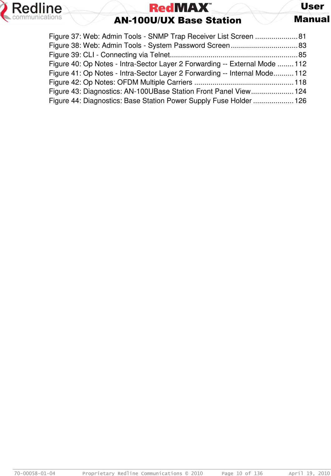
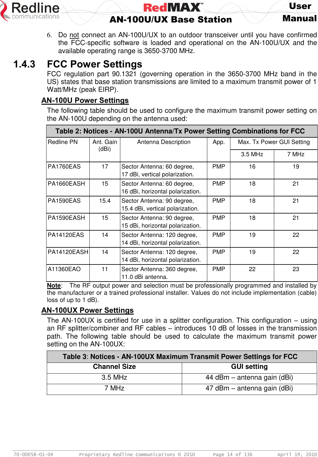
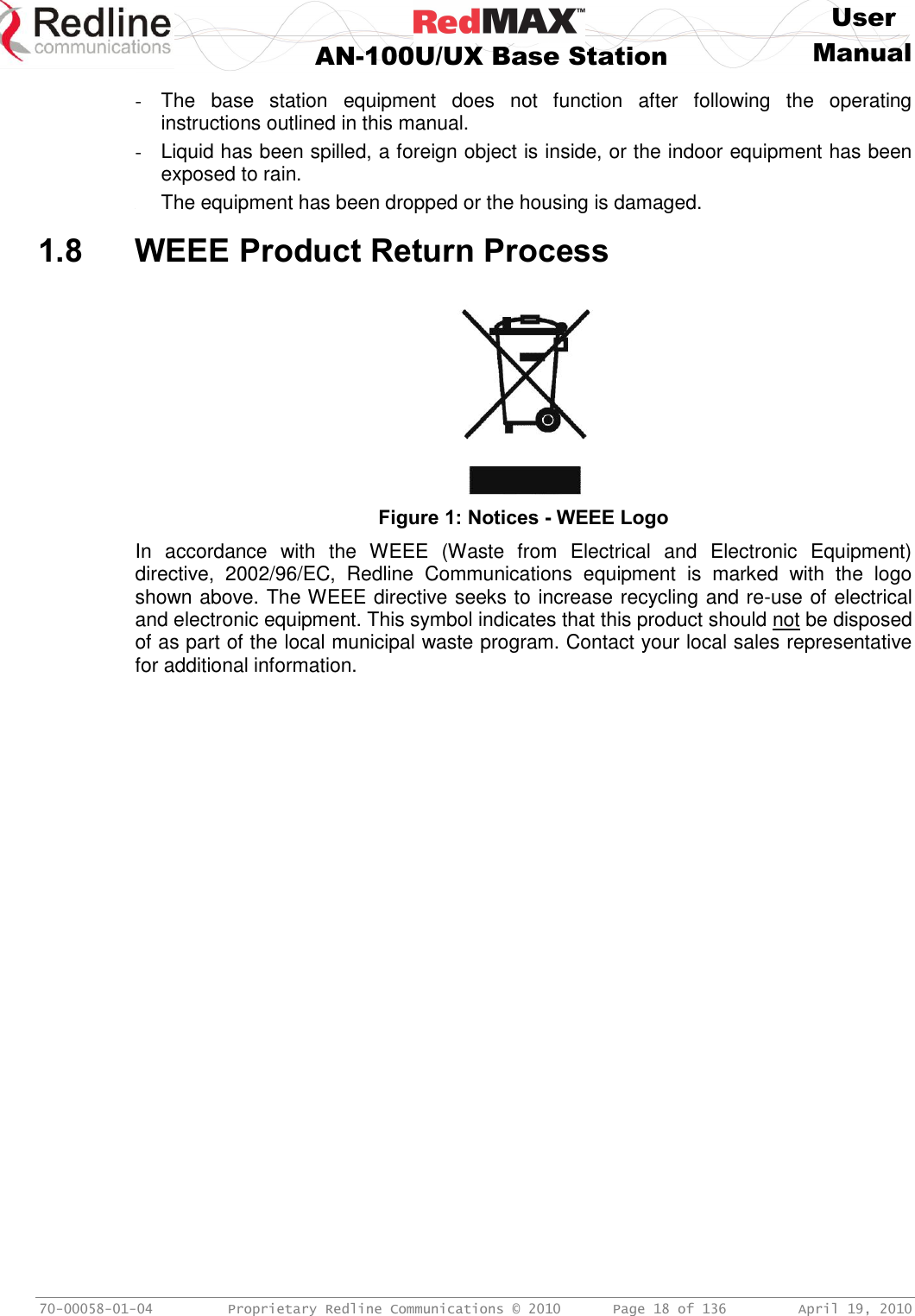
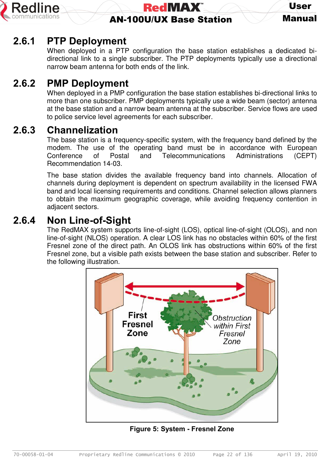
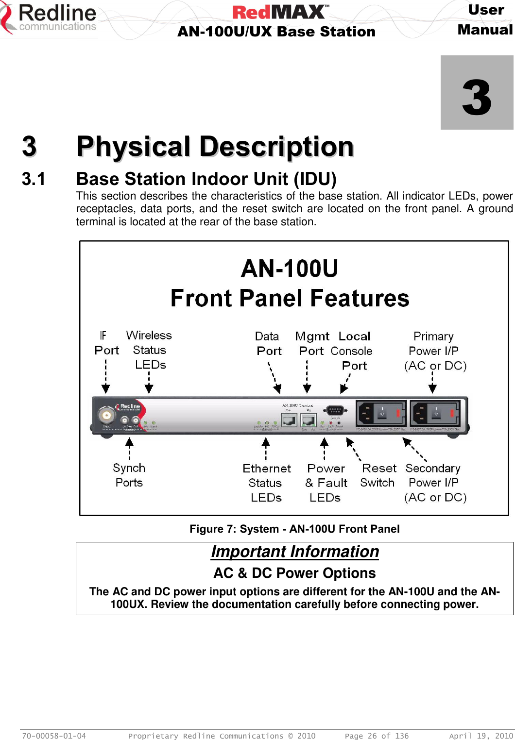
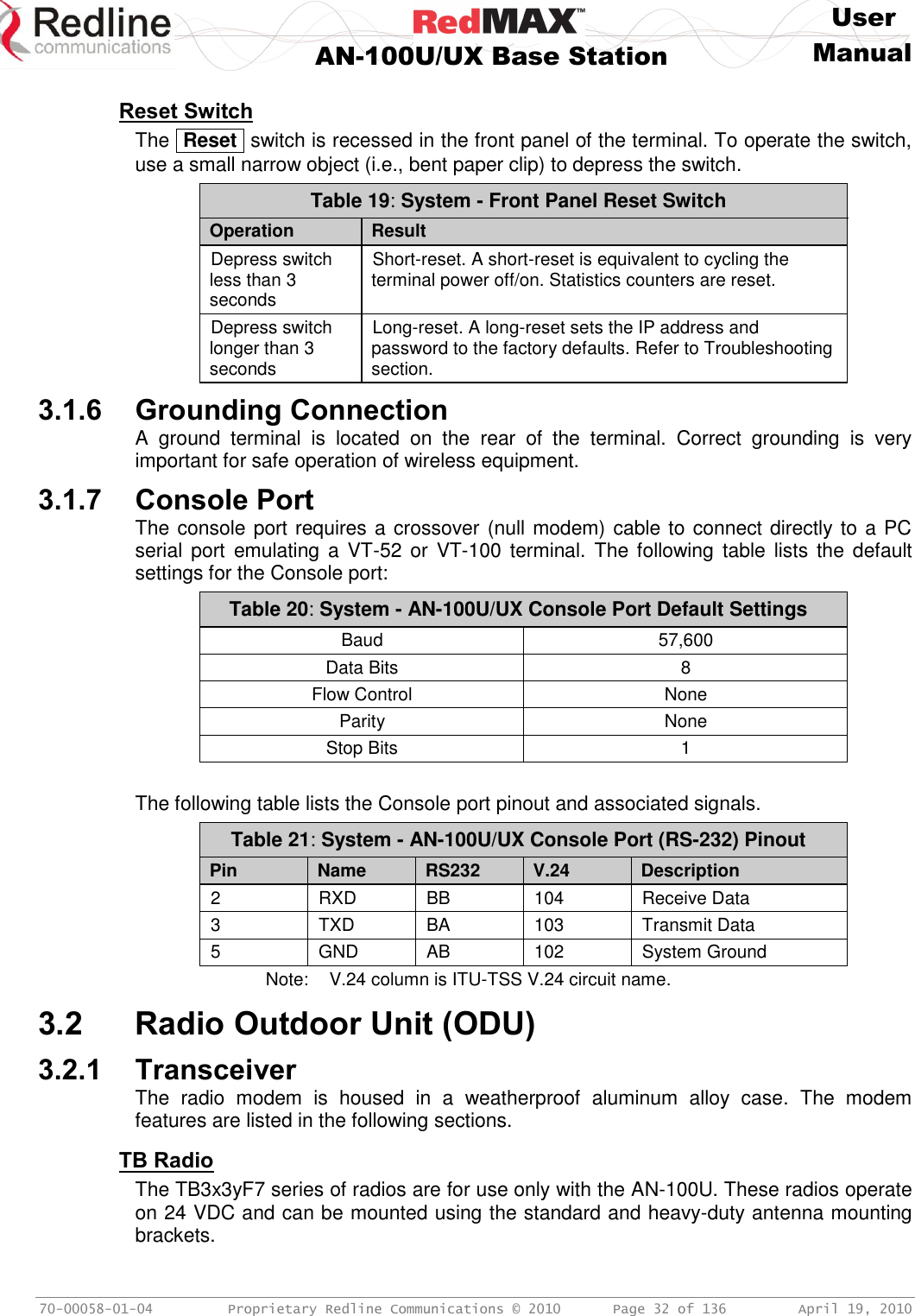
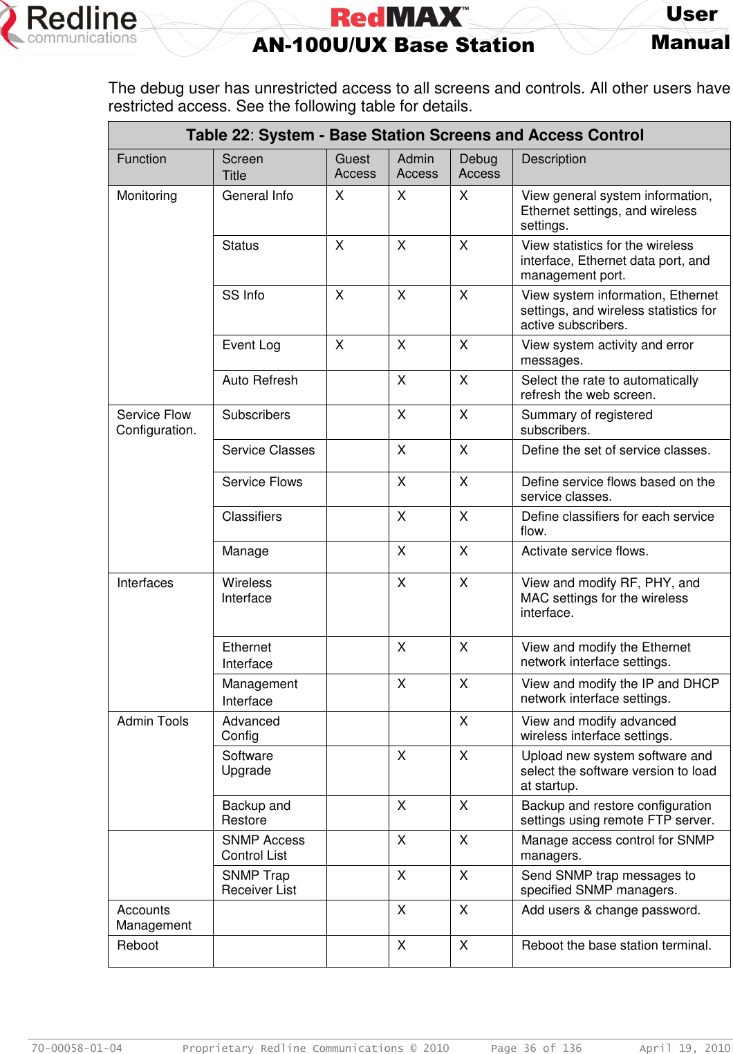
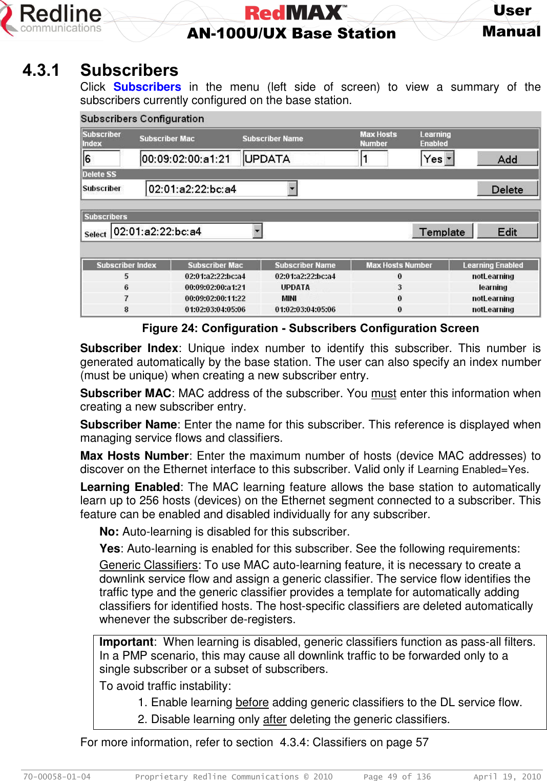
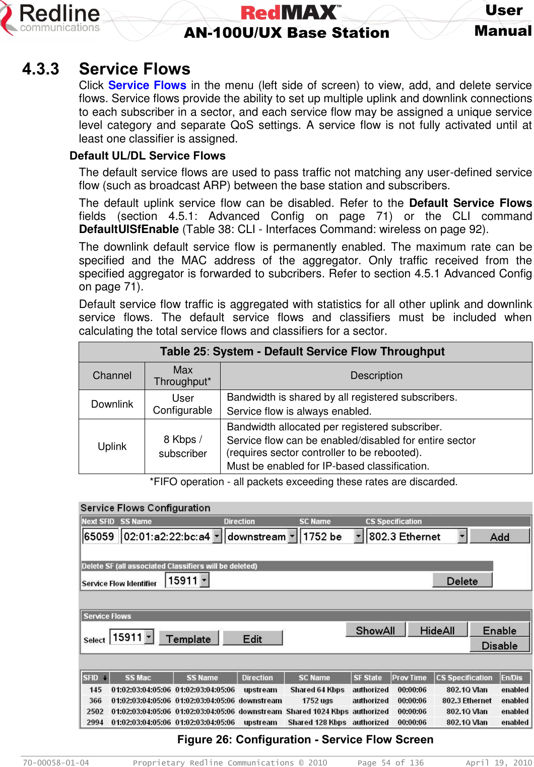
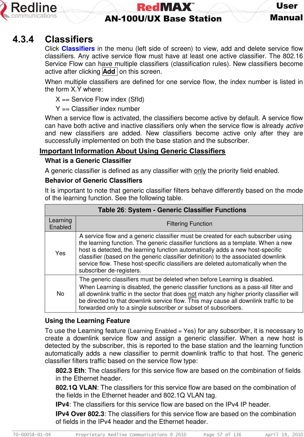
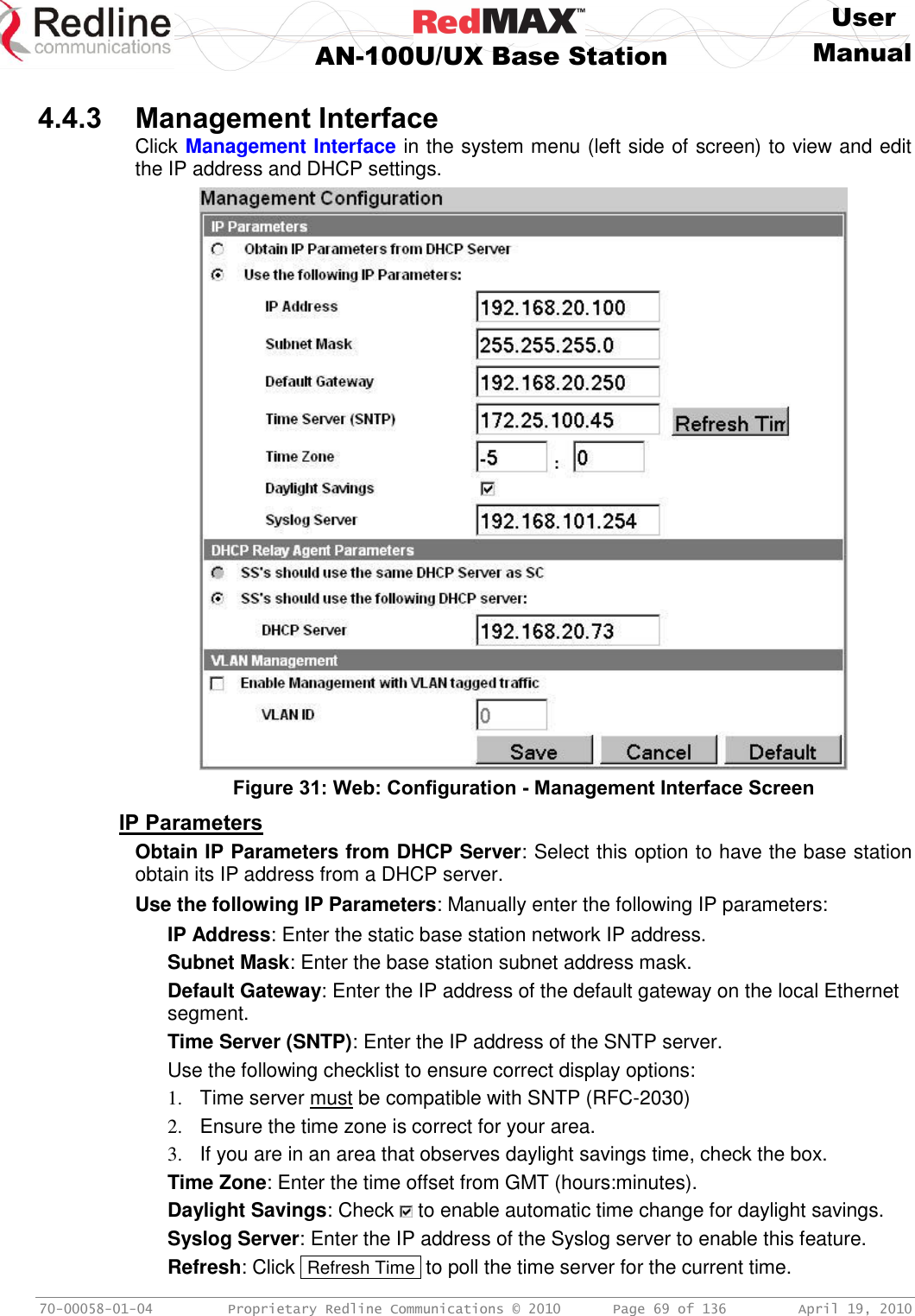
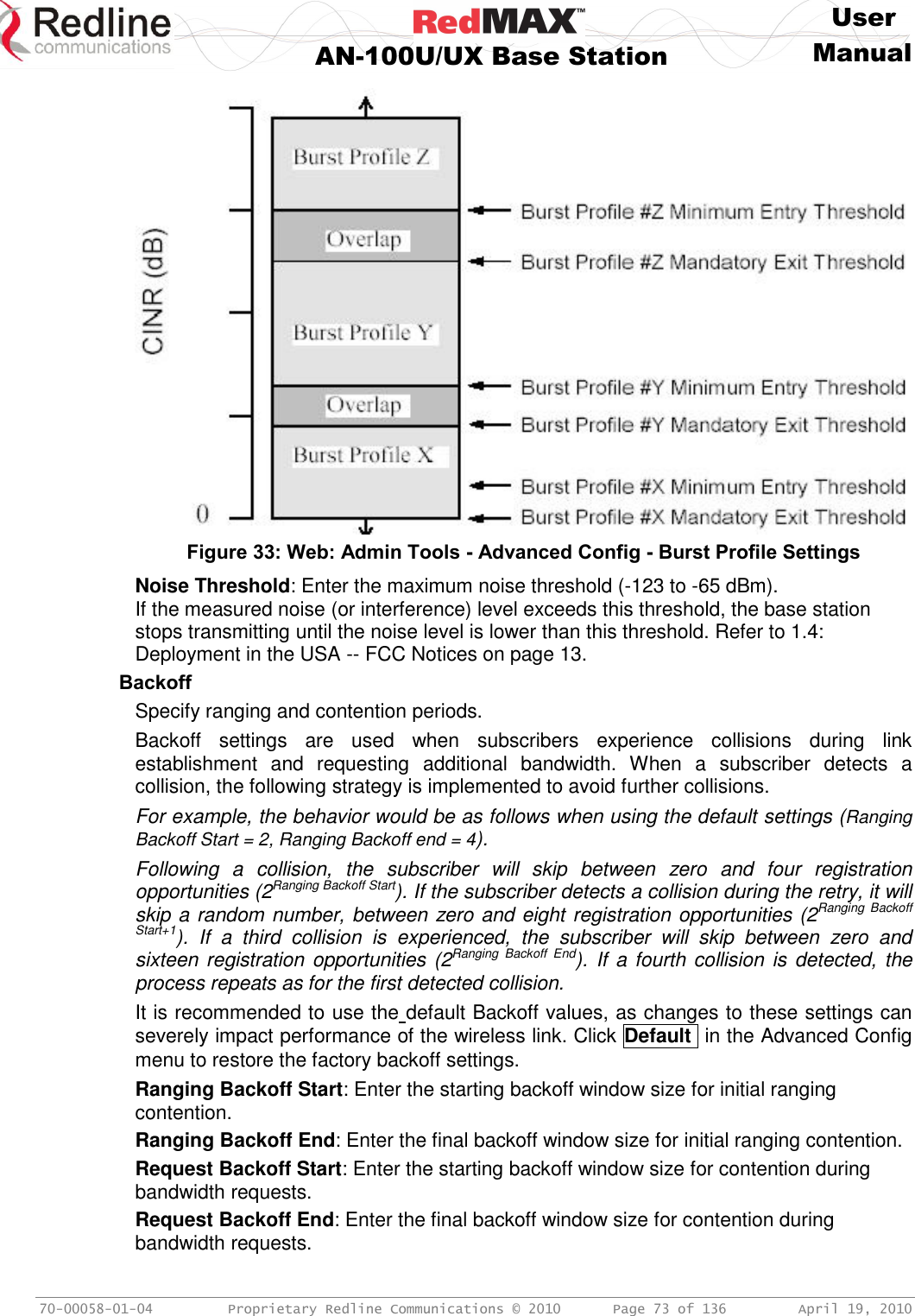
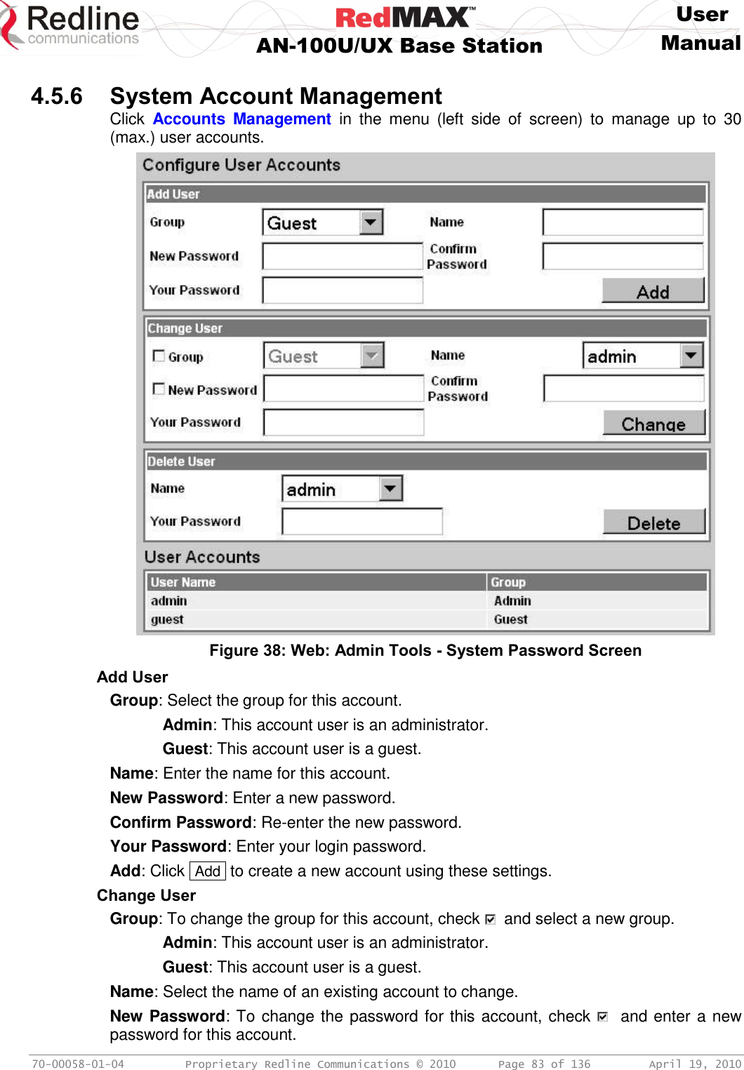
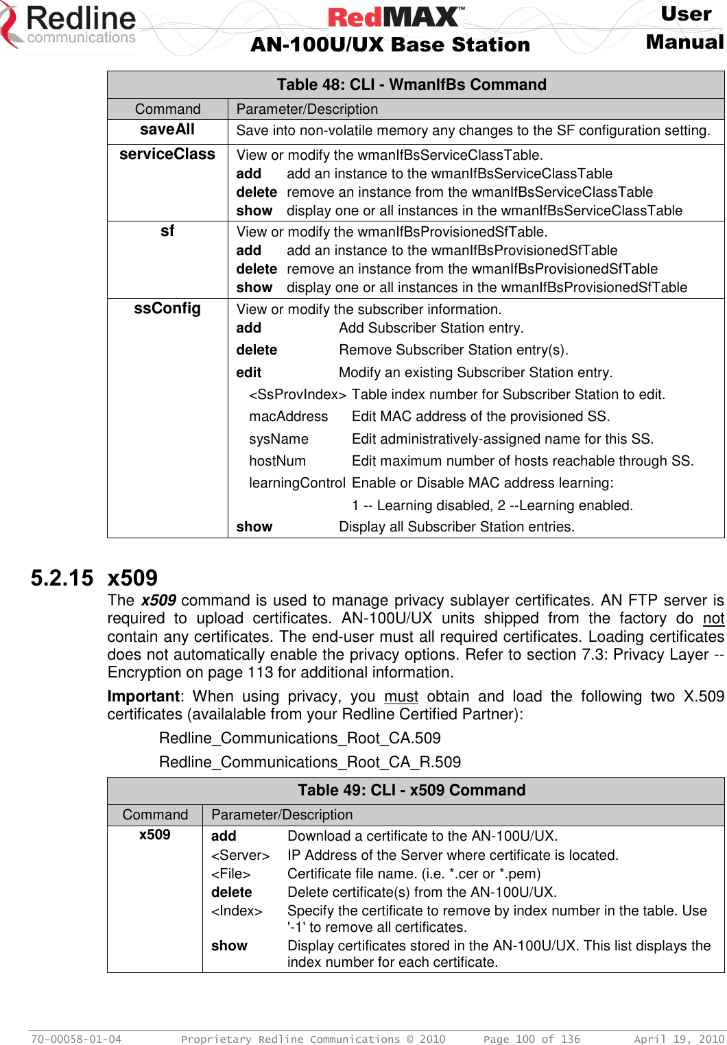
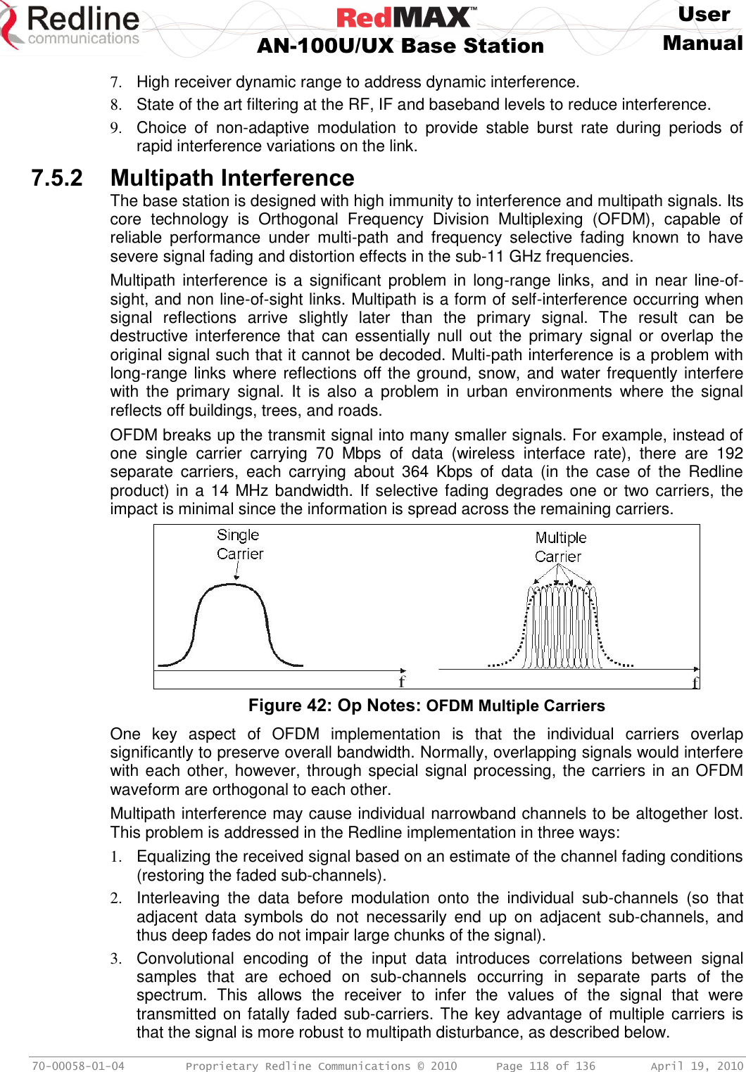
![User AN-100U/UX Base Station Manual 70-00058-01-04 Proprietary Redline Communications © 2010 Page 27 of 136 April 19, 2010 Figure 8: System - AN-100UX Front Panel 3.1.1 Mounting The indoor equipment can be freestanding on a flat surface or in a 19-inch rack. 3.1.2 Power Supply The AN-100U and AN-100UX (high power) equipment have different power supply features. Read the following section carefully to determine the correct power requirements and options. All models feature double pole/neutral fusing. Refer to the Installation Guidelines manual for additional information about DC power wiring. Warning to service personnel: Caution for all AC and DC models – Double Pole/Neutral fusing. AN-100U Power supply options include single or dual AC or DC supplies, or a combination of AC and DC power supplies. Cables are included with both AC and DC power supplies. Table 7 - IDU Installation - RedMAX AN-100U Power Specifications Voltage range [V] Tolerance [%] Power consumption max. [W] Max. Current [A] Inrush current 1 [A] AC Input 2 100-240 VAC 10% 75 2 35 DC Input 2 24-60 VDC 20% 75 6 40 1. Typical Inrush current is less then 500 us. DC: measured, AC: P/S manufacturers data. 2. Auto-sensing.](https://usermanual.wiki/Redline-Communications/AN100UAE/User-Guide-1342304-Page-27.png)
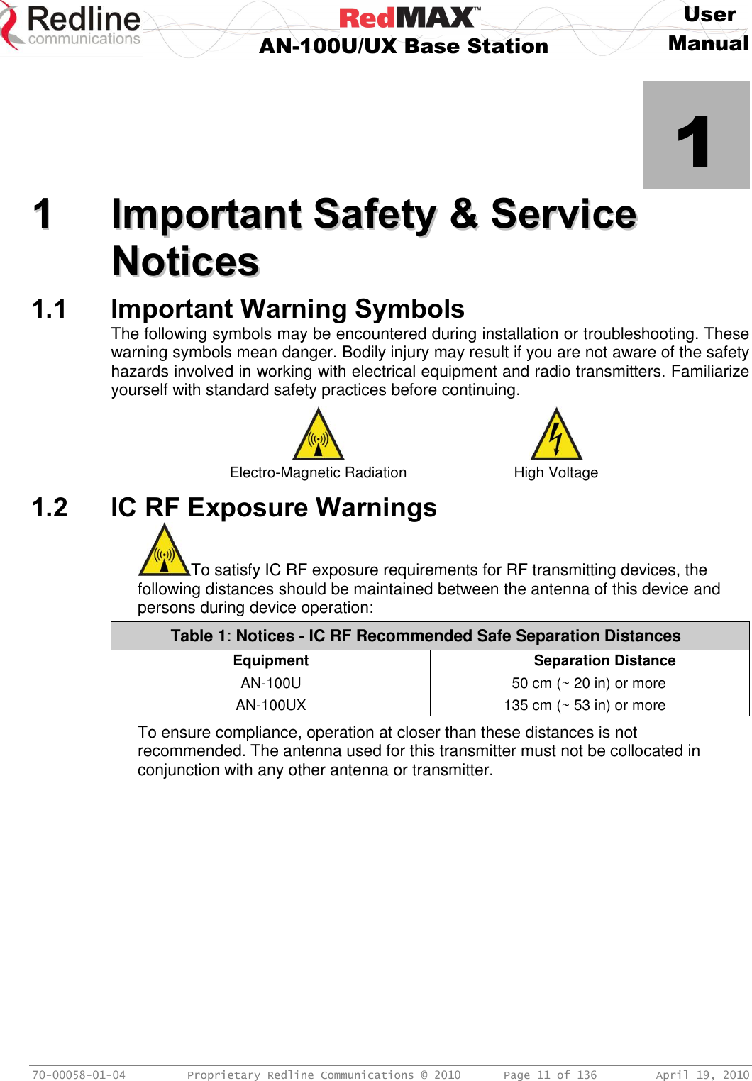
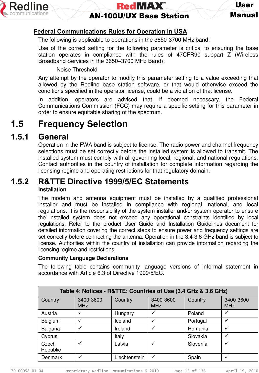
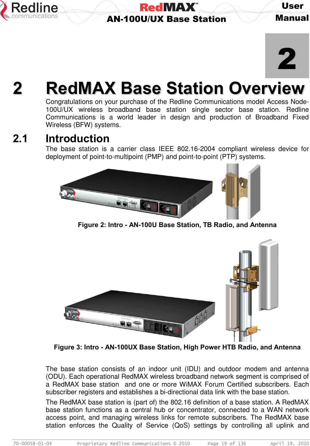
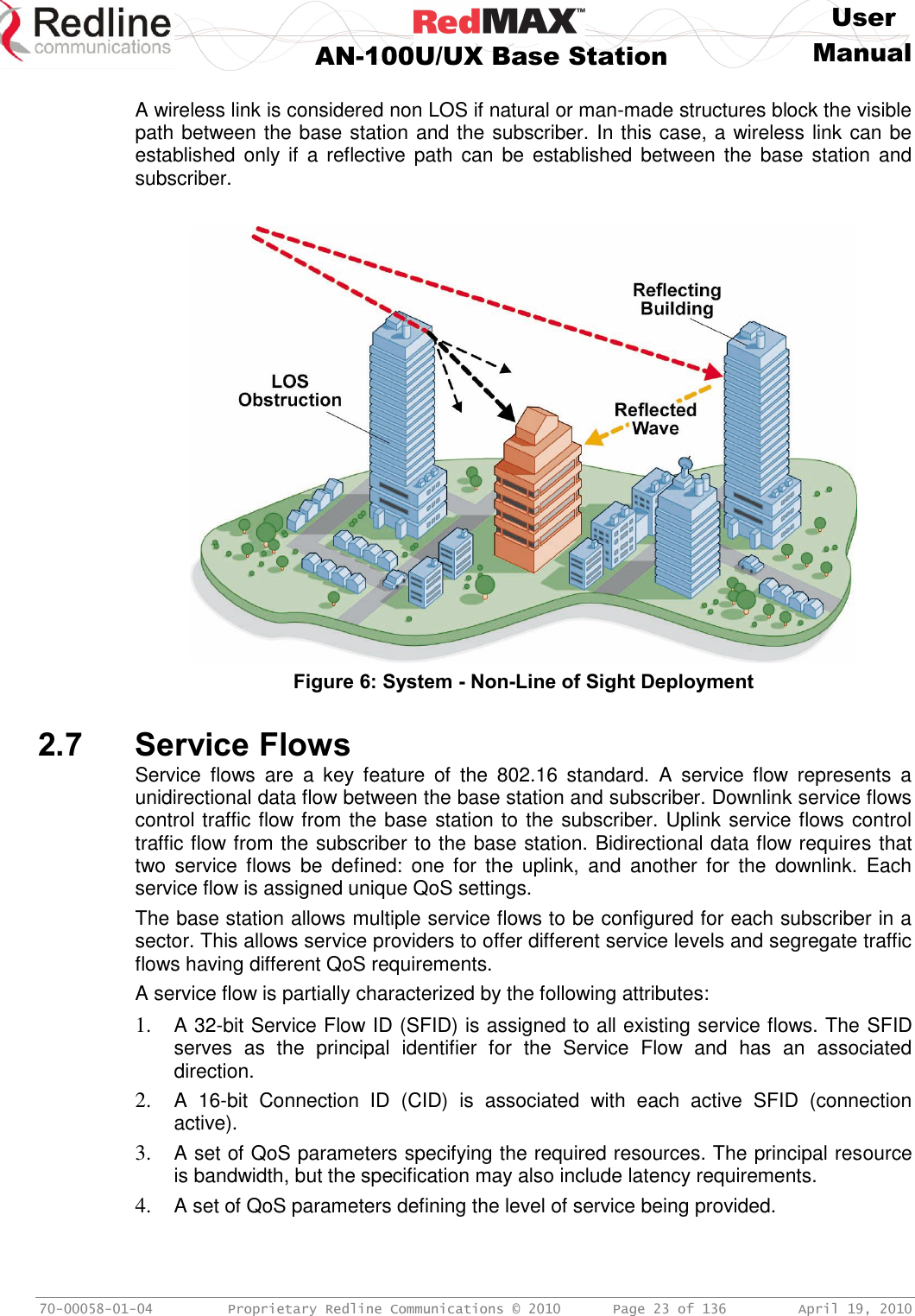
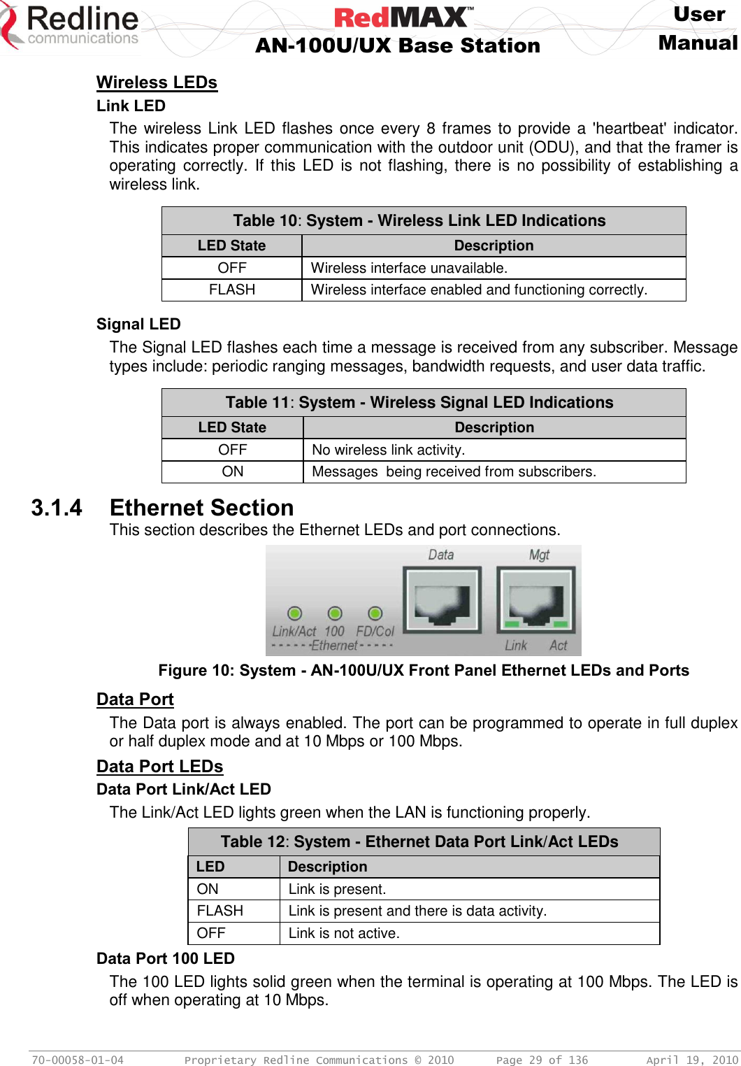
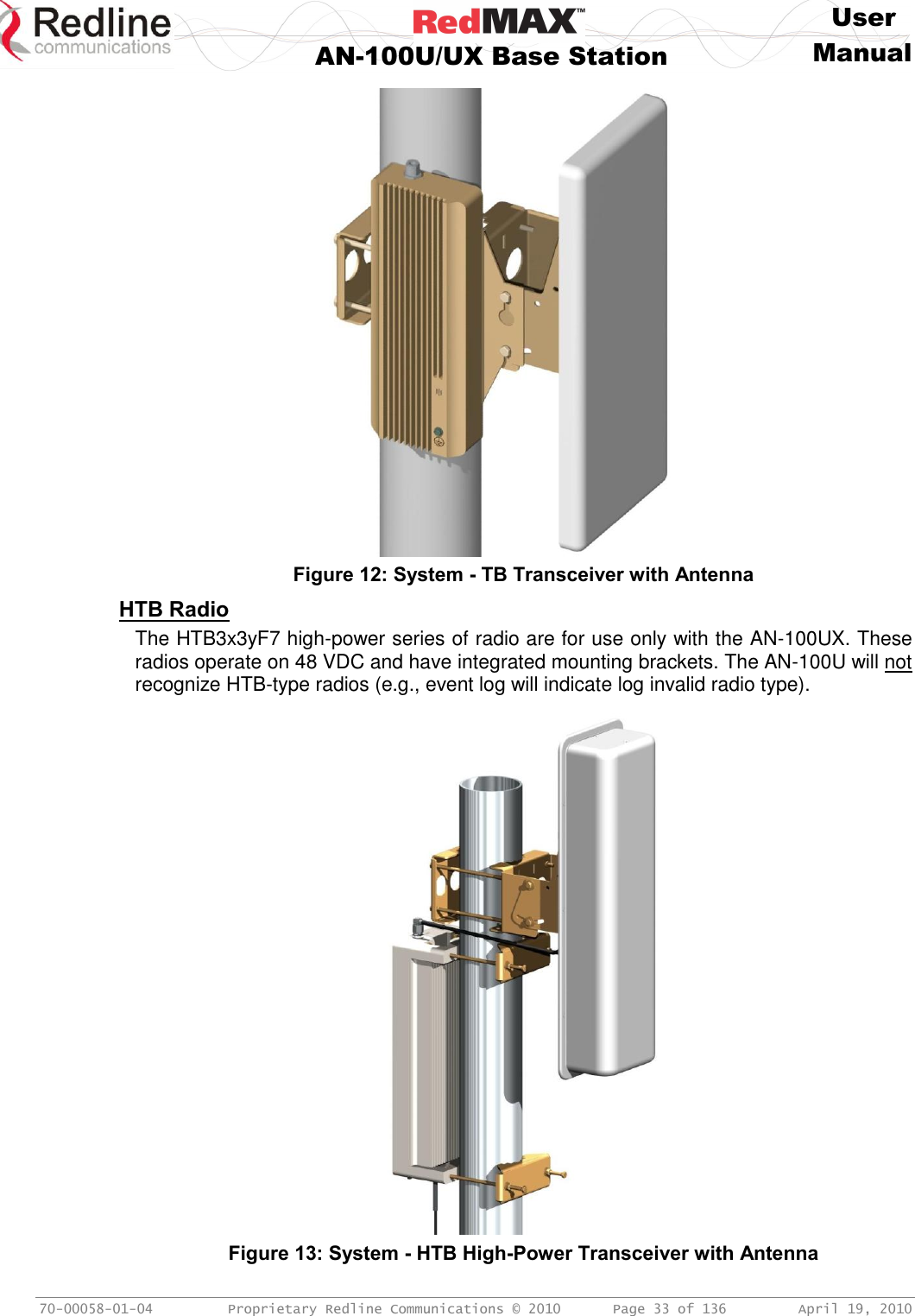
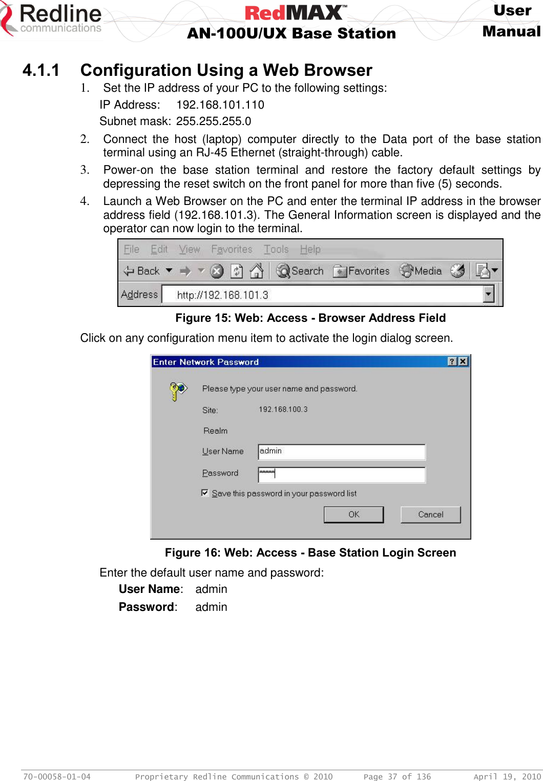
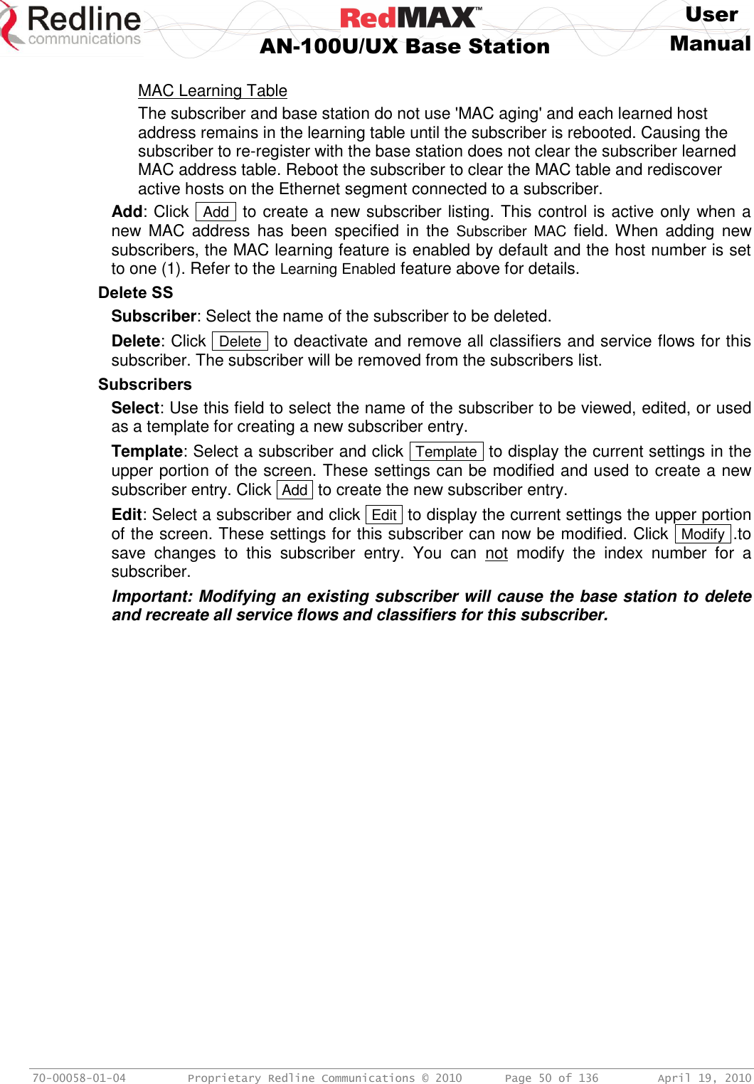
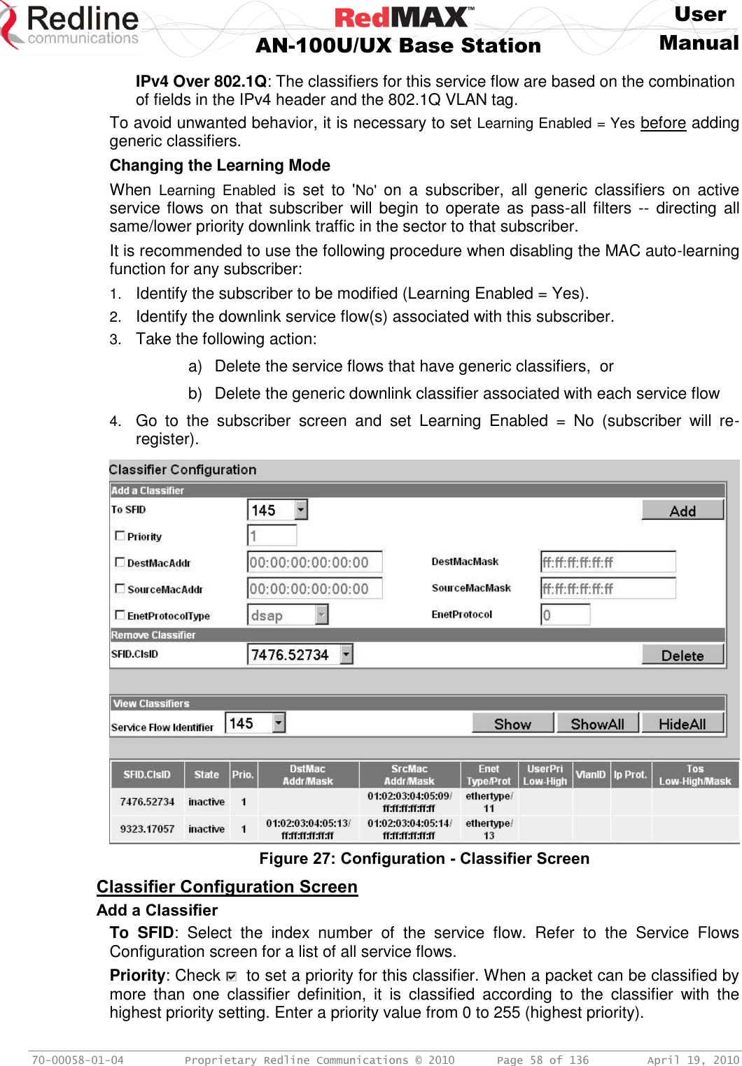
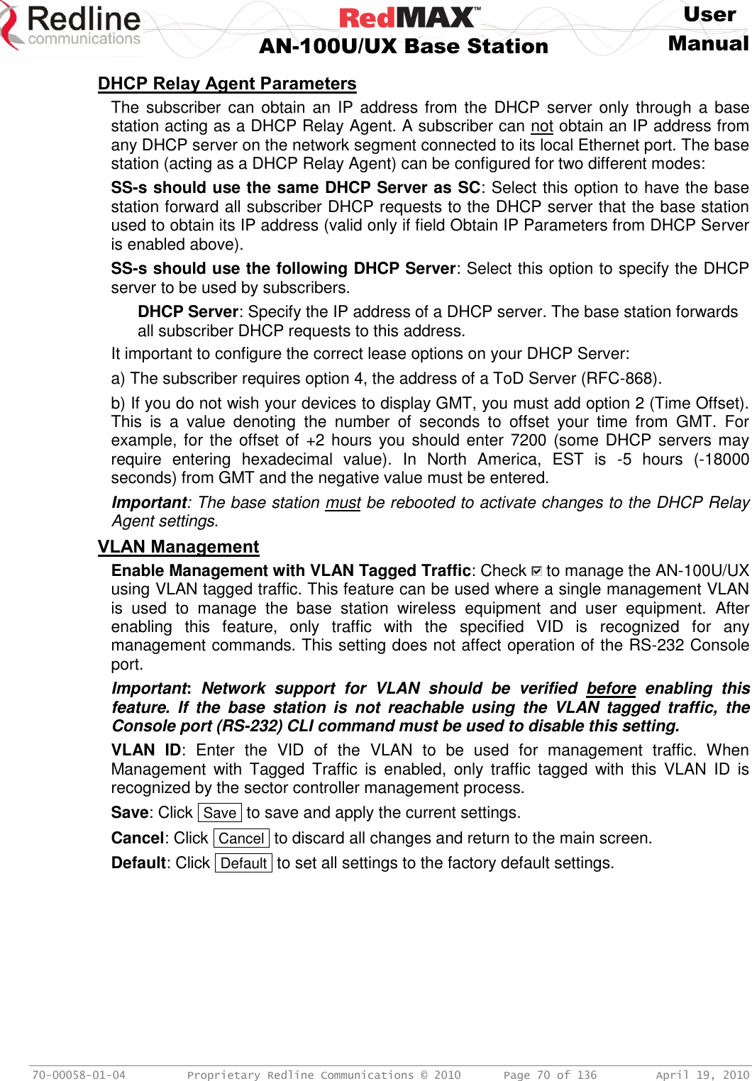
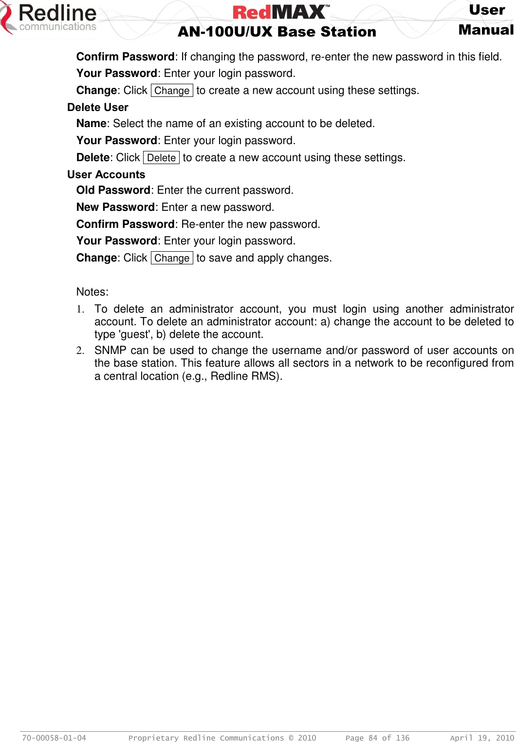
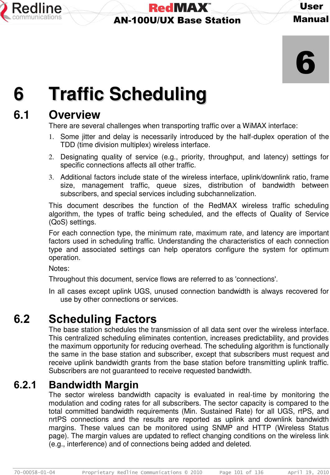
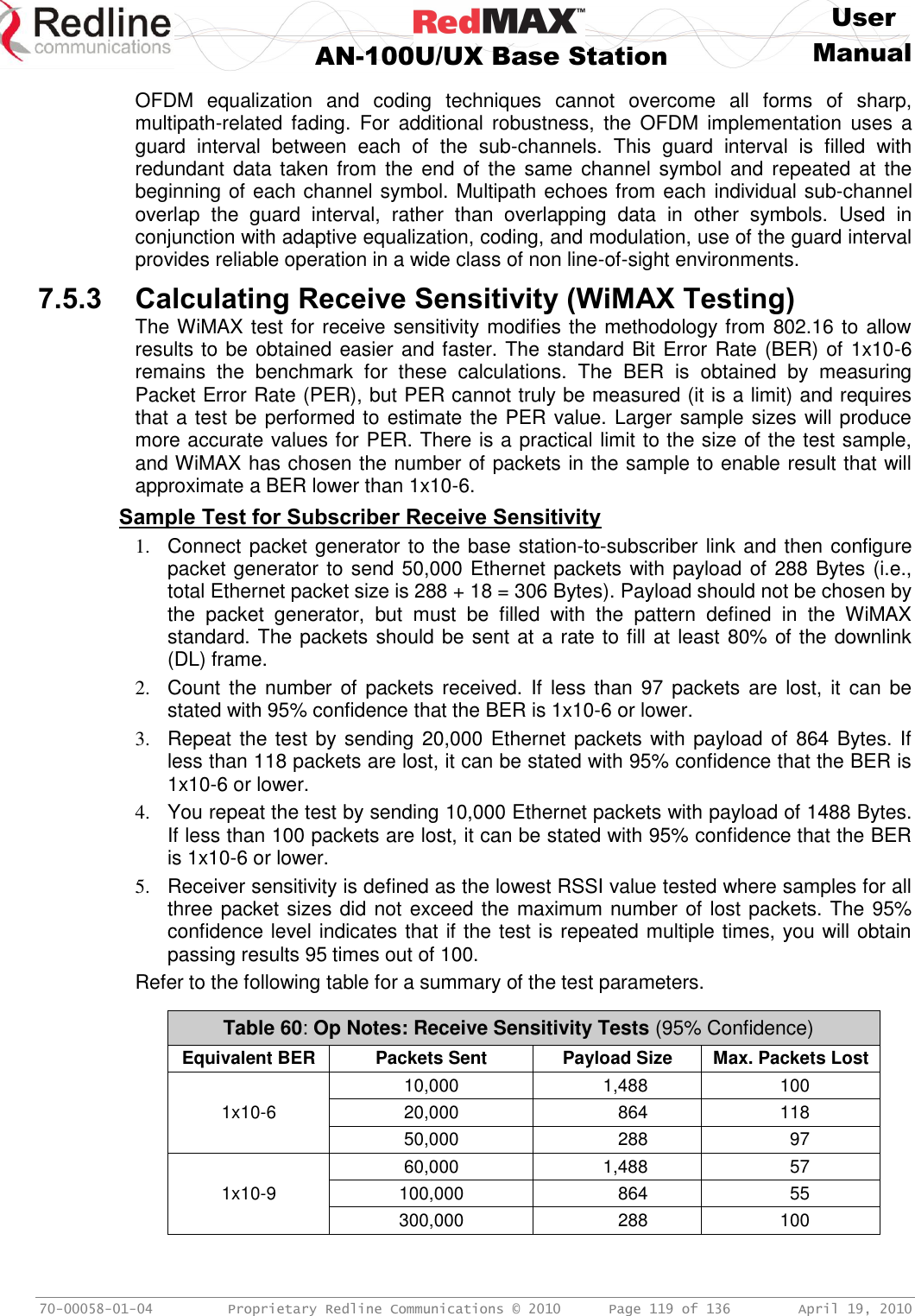
![User AN-100U/UX Base Station Manual 70-00058-01-04 Proprietary Redline Communications © 2010 Page 28 of 136 April 19, 2010 AN-100UX AN-100UX Power supply options include single AC or DC types. Cables are included with AC and DC power supplies. Backup power can be supplied only from a +48 VDC power supply. Table 8 - IDU Installation - RedMAX AN-100UX Power Specifications Voltage range [V] Tolerance [%] Power consumption max. [W] Max. Current [A] Inrush current 1 [A] Main AC Input 2 100 - 240 VAC 10% 120 2 100 Main DC Input 48 - 60 VDC 20% 120 5 70 Backup. DC Input +48 VDC 5% 120 5 30 1. Typical Inrush current is less then 500 us. DC: measured, AC: P/S manufacturers data. 2. Auto-sensing. IMPORTANT: DC Polarity The AN-100UX backup power supply is DC type and must be connected using positive polarity: the +48 VDC must be connected to +Ve input on the AN-100UX. Refer to Installation Guidelines for additional details. 3.1.3 Wireless Section This section describes the wireless port, time synchronization ports, and wireless LEDs. Figure 9: System - AN-100U/UX Front Panel Wireless Section IF Port (Radio Control) A female N-type port provides connection via a coaxial cable. This port provides the following functions: - Local oscillator signal for synchronization between the terminal and radio - Telemetry signals for control and monitoring the modem - IF modulated data to/from the radio (wireless interface) - DC power to the transceiver (see following table) Table 9: System - AN-100U/UXIF Cable Voltage AN-100U 24 VDC AN-100UX 48 VDC Time Synchronization Port The synchronization interface has two SMA female connectors located on the front panel. Refer to section for additional information. When operating two or more collocated base stations (BSs), transmitter operations MUST use synchronization to minimize inter-sector interference. Refer to the RedMAX Base Station Installation Guidelines for complete details.](https://usermanual.wiki/Redline-Communications/AN100UAE/User-Guide-1342304-Page-28.png)
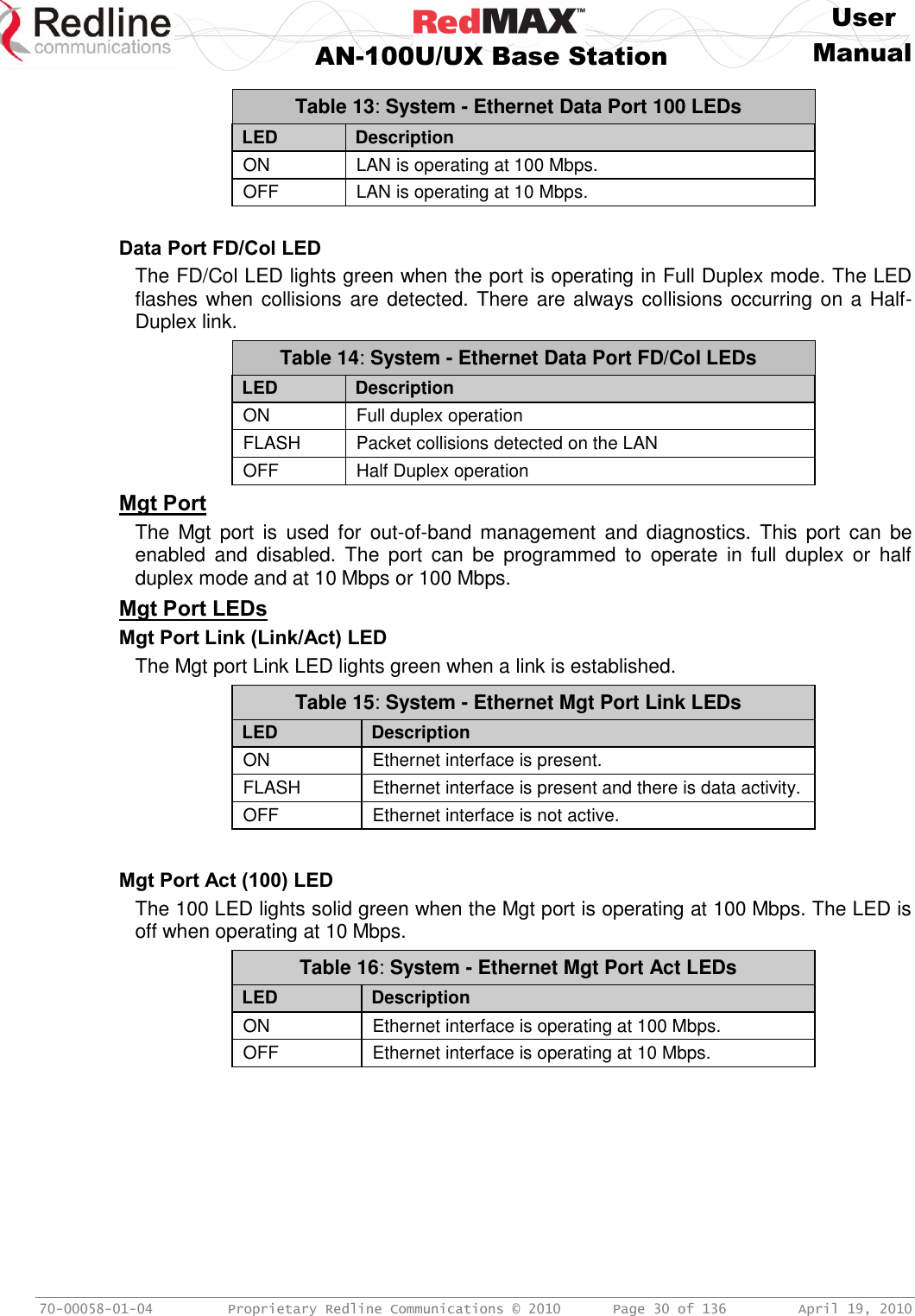
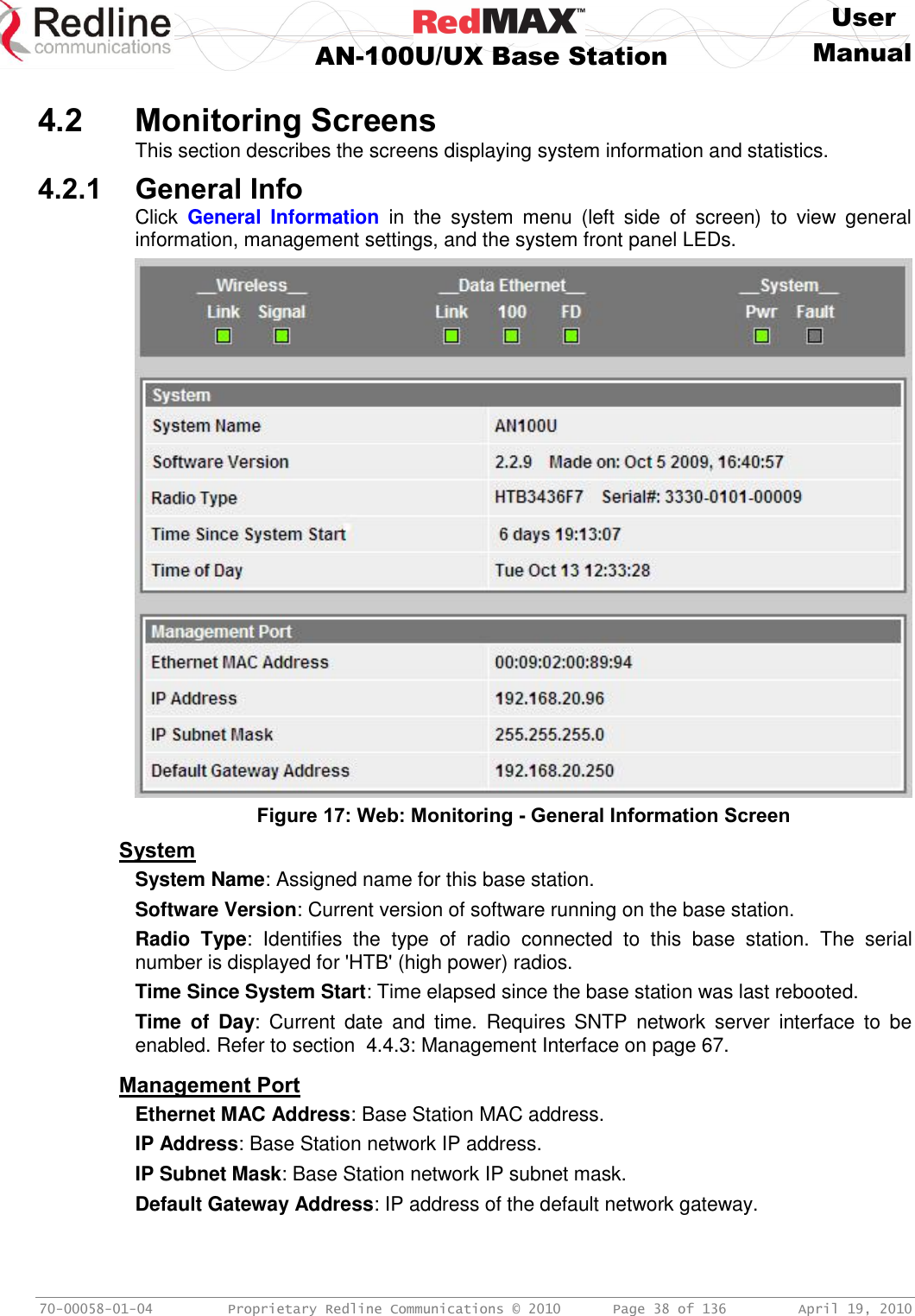
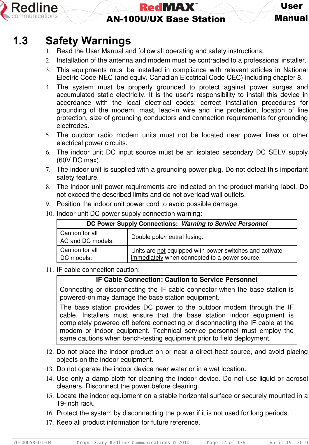
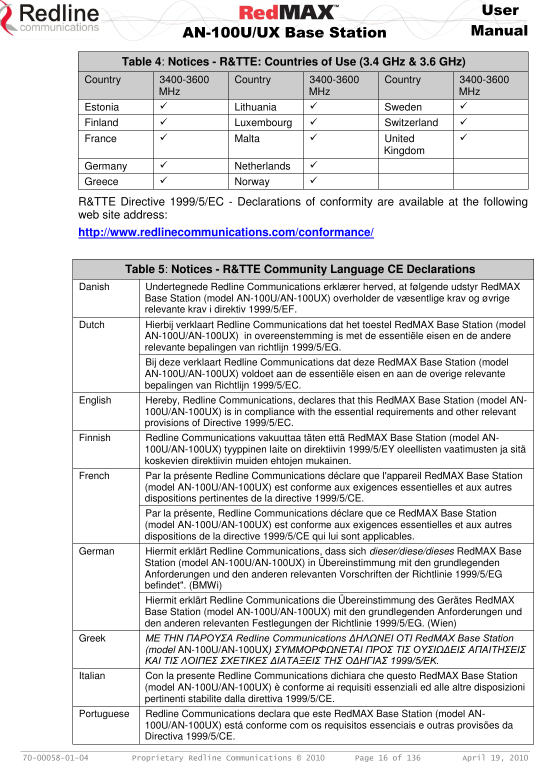
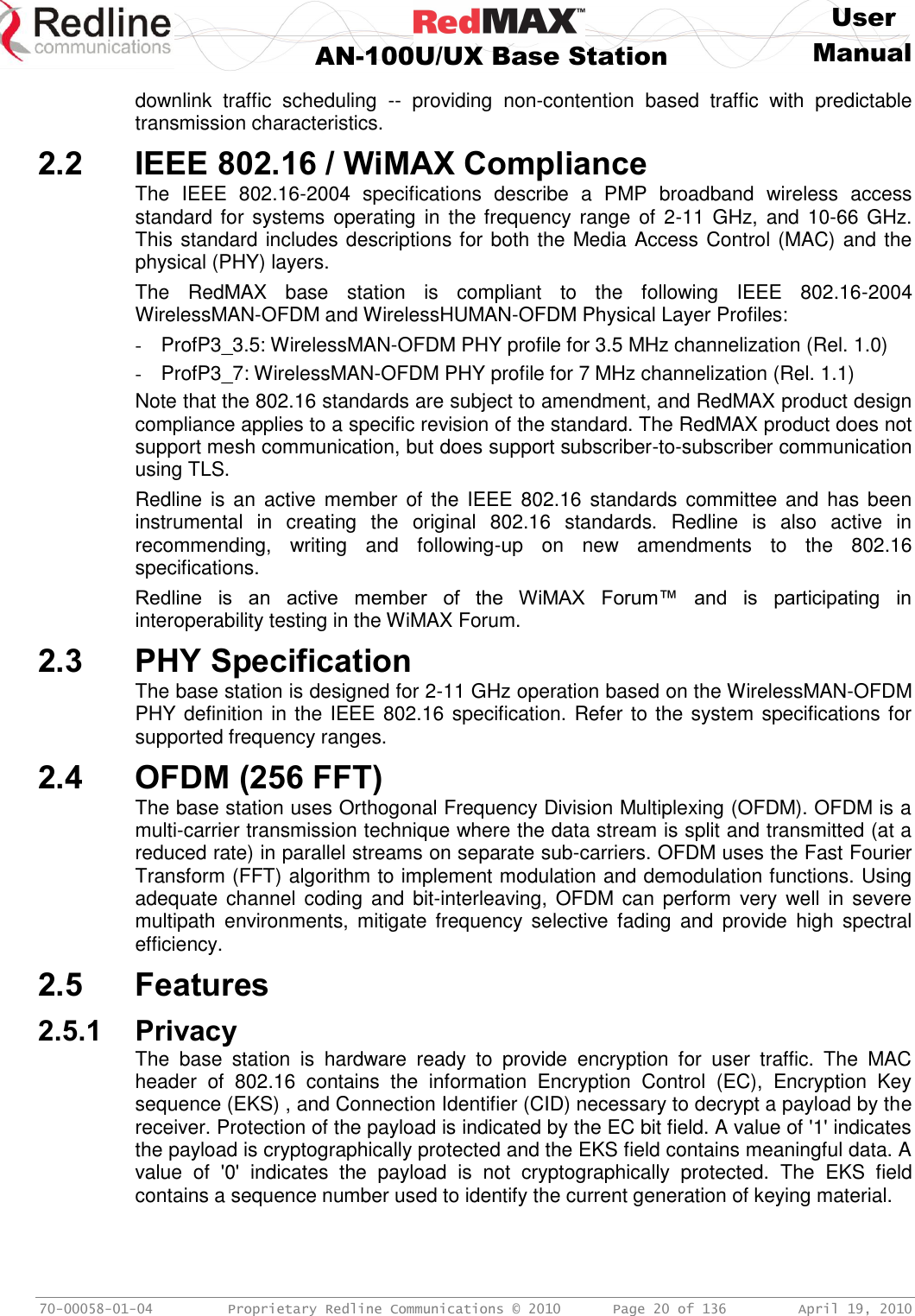
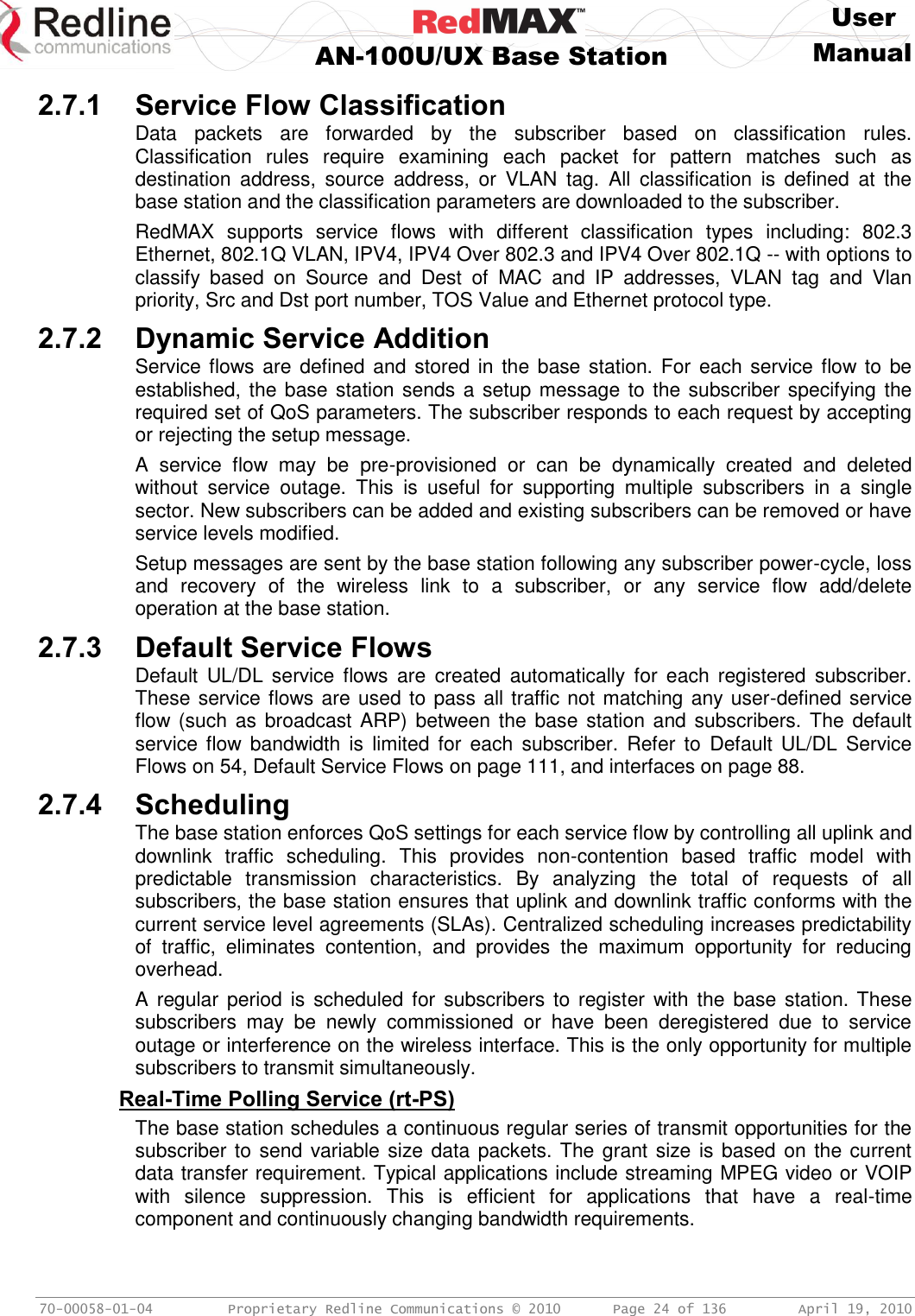
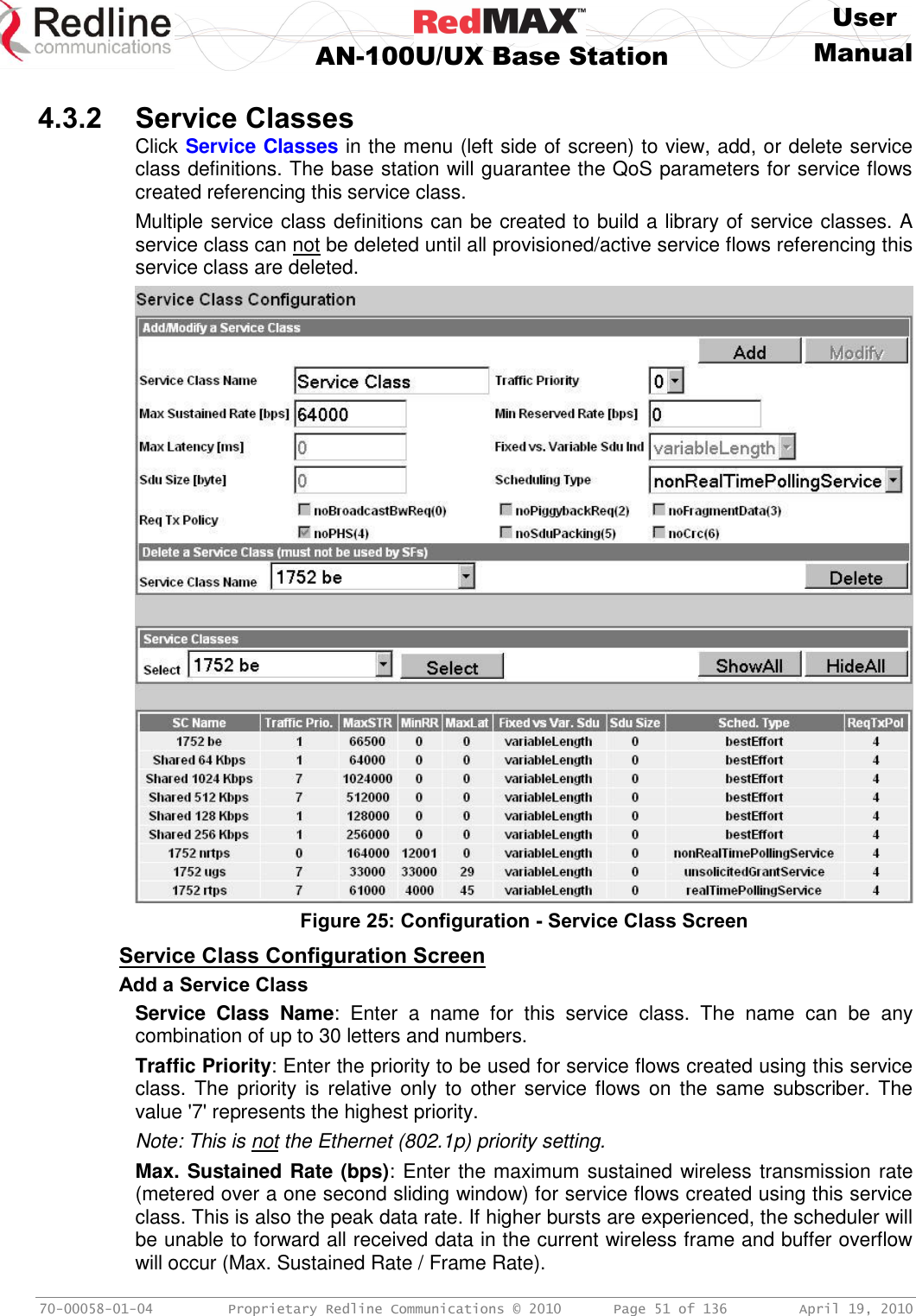
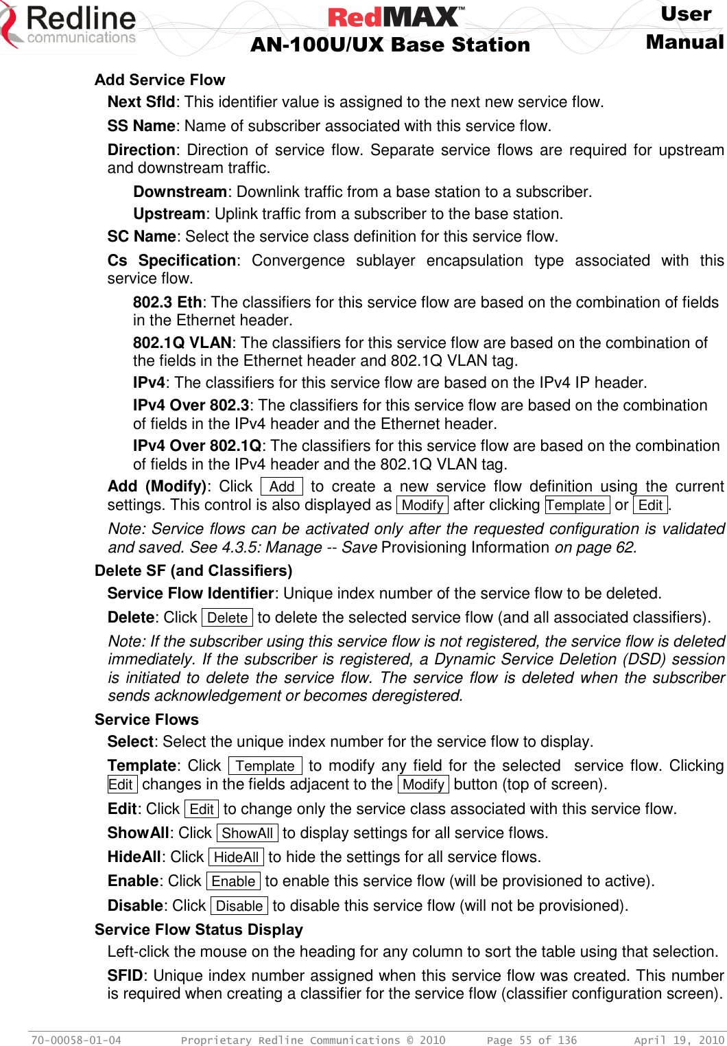
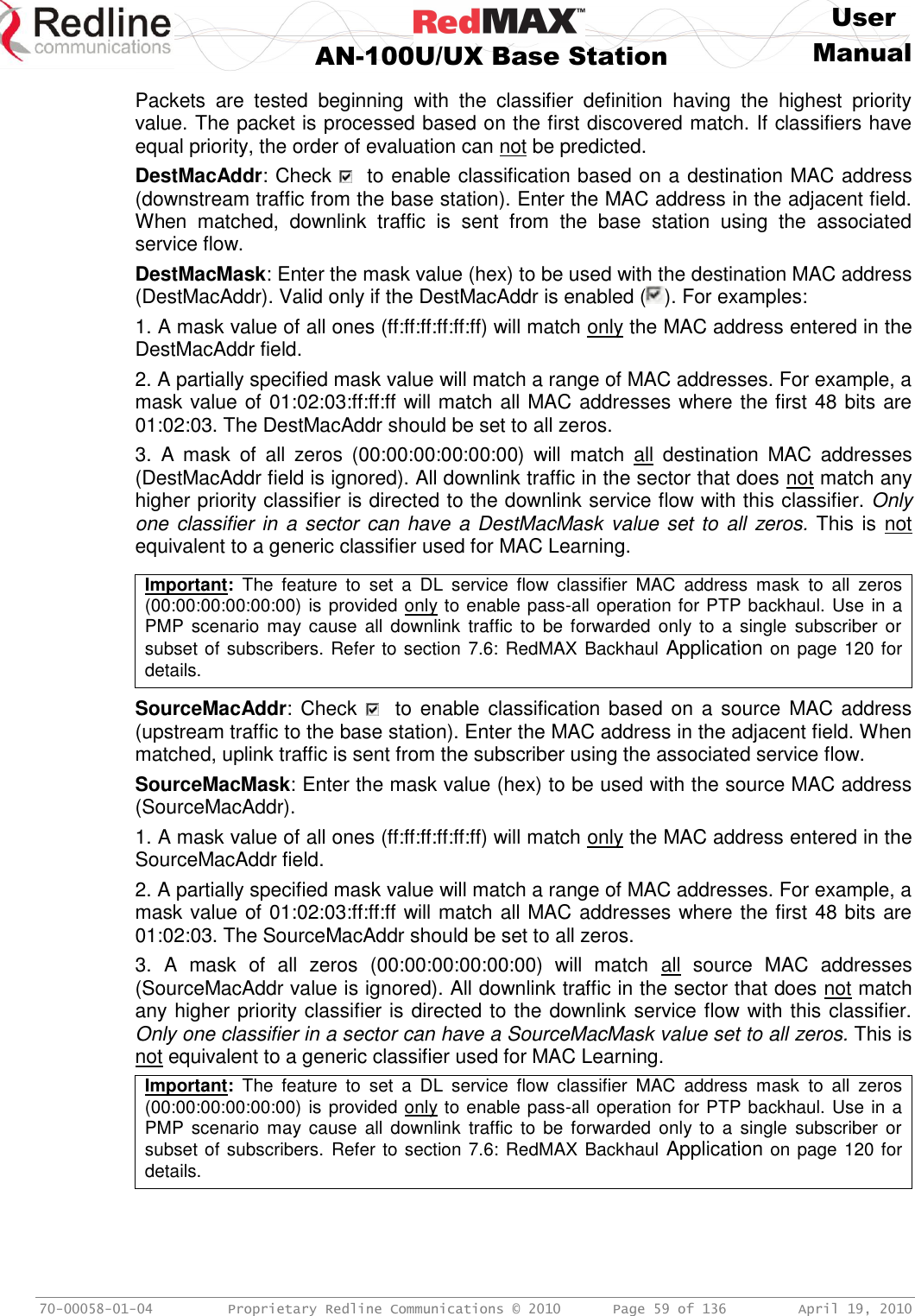
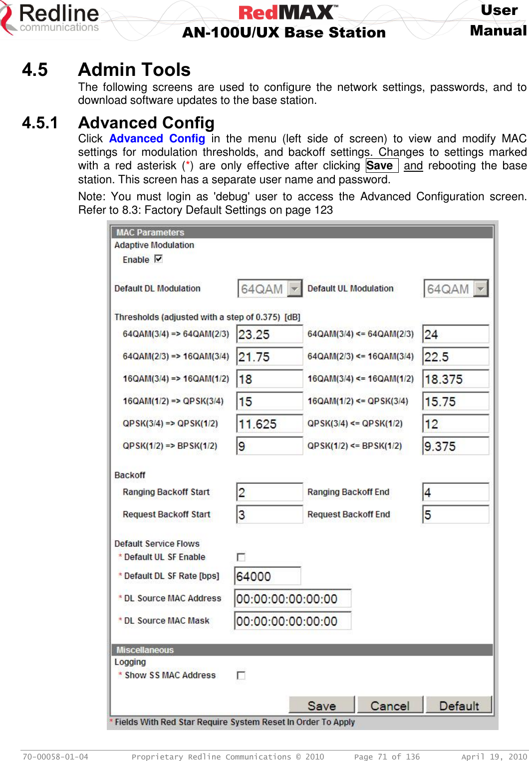
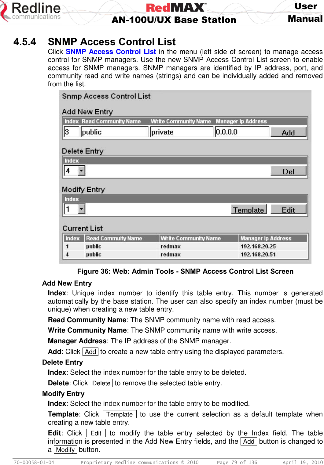
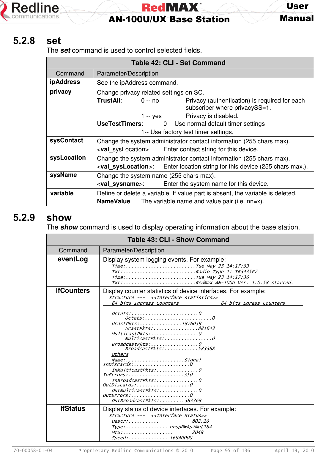
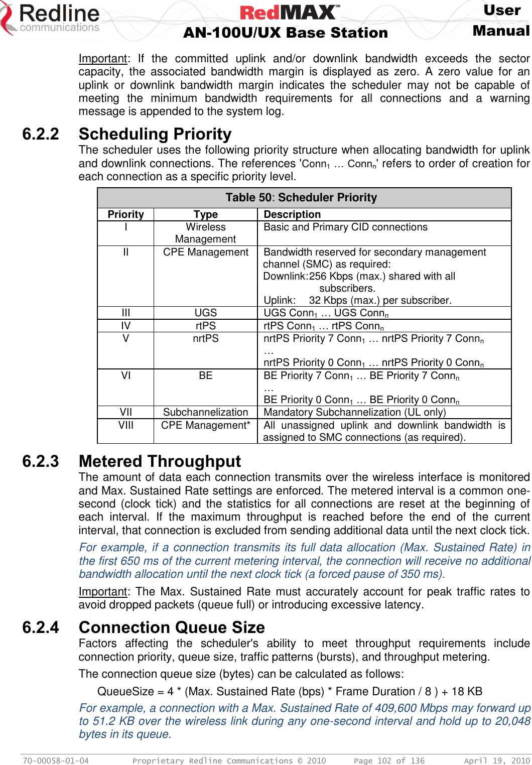
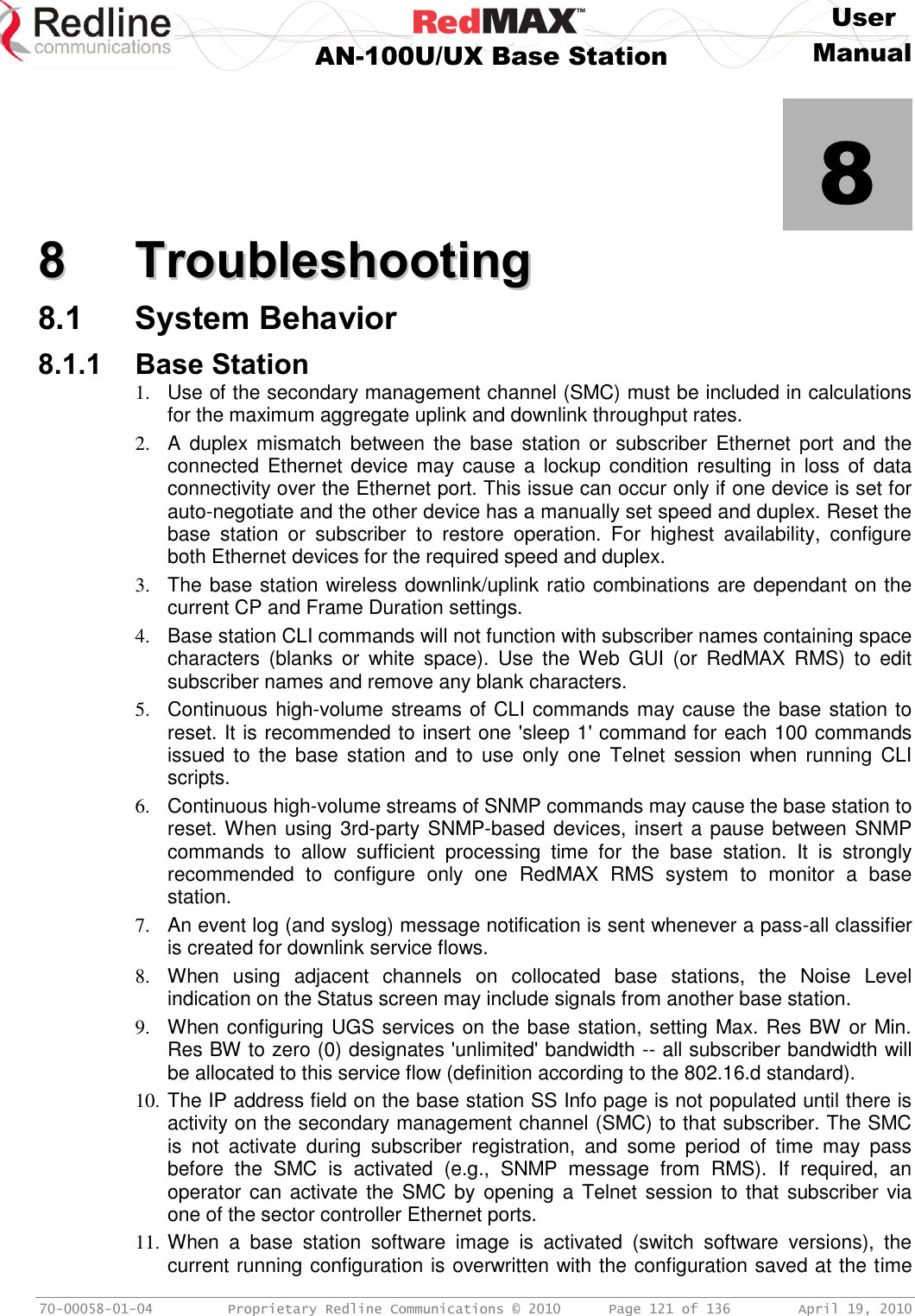
![User AN-100U/UX Base Station Manual 70-00058-01-04 Proprietary Redline Communications © 2010 Page 39 of 136 April 19, 2010 4.2.2 Status Click Status in the system menu (left side of screen) to view status information about the wireless interface and Ethernet management interface. Values are updated according to the screen refresh rate. Figure 18: Web: Monitoring - Status - Wireless Status Screen Wireless Status CINR [dB]: Mean Carrier/(Interference + Noise) ratio. The CINR value is calculated and displayed for each automatic screen refresh. The CINR measured by the base station is based on the signal from the subscriber. Based on this value, the base station may request that the subscriber change modulation rate. Traffic Downlink [kbps]: Rate of traffic transmitted to subscribers. BW Margin Downlink [kbps]: Downlink bandwidth available that can be scheduled by the base station, based on the minimum traffic settings for all downlink service flows. This value is affected by: current downlink modulation for each subscriber, downlink service flows being added or deleted, and the base station downlink ratio. This value is available through the Web interface Status page, SNMP, and CLI. If this value becomes zero, a warning message is entered in the base station log. CRC Errors: Number of CRC errors detected on packets received from subscribers. This counter is reset when the base station is rebooted. Note: The CRC Errors counter in the SS Info screen is reset when a subscriber is registered. Air Interface Status: Status of the base station modem: Enabled - Transceiver is operating normally. Disabled - Transceiver is disconnected, disabled, or defective. IDU Temperature [Celsius]: Internal temperature of the indoor terminal. Power Supply Status: Display the status of the power circuits.](https://usermanual.wiki/Redline-Communications/AN100UAE/User-Guide-1342304-Page-39.png)
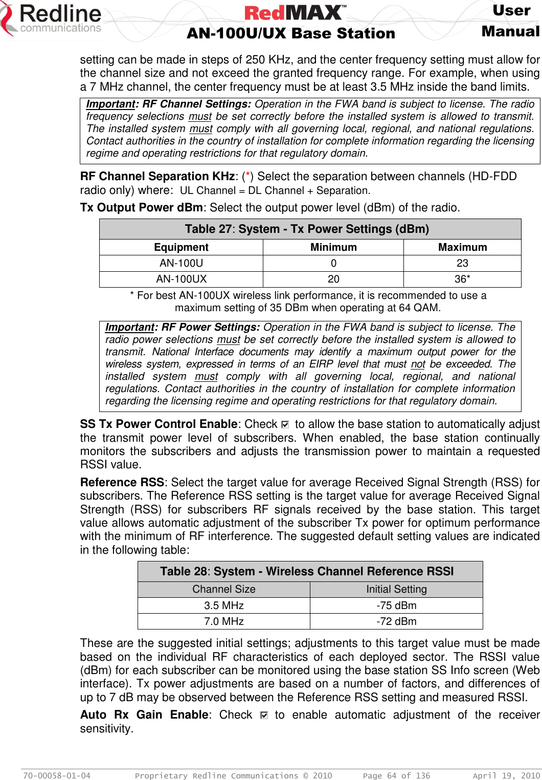
![User AN-100U/UX Base Station Manual 70-00058-01-04 Proprietary Redline Communications © 2010 Page 40 of 136 April 19, 2010 A-On - Terminal is equipped with AC circuits only. D-On - Terminal is equipped with DC circuits only. A-D - Terminal is equipped with AC and DC circuits. Active DL Service Flows: Number of currently active downlink service flows. DL SMC Rate [kbps]: Data rate for SMC channel. DL Bandwidth Usage [%]: Current usage of downlink channel. Reference RSS [dBm]: The Reference RSS setting is the target value for average Received Signal Strength (RSS) for subscribers RF signals received by the base station. This target value allows automatic adjustment of the subscriber Tx power for optimum performance with the minimum of RF interference. The suggested default setting for the Reference RSS value is: Table 23: Configuration - Reference RSS (dBm) Channel Size Initial Setting 3.5 MHz -75 dBm 7.0 MHz -72 dBm These are the suggested initial settings; adjustments to this target value must be made based on the individual RF characteristics of each deployed sector. The RSSI value (dBm) for each subscriber can be monitored using the base station SS Info screen (Web interface). Tx power adjustments are based on a number of factors, and differences of up to 7 dB may be observed between the Reference RSS setting and measured RSSI. Narrowest Subchannel: The narrowest mandatory sub-channel type available to use with the current configuration (Channel Bandwidth, Frame Duration, Cyclic Prefix and DL Ratio) and basic management activity. Refer to the folllowing table for details. Table 24: Configuration - Subchannelization Status Status Message Available Subchannelization Types fullChannel Full only 1/2 subchannel Full, and 1/2 1/4 subchannel Full, 1/2, and 1/4 1/8 subchannel Full, 1/2, 1/4, and 1/8 1/16 subchannel Full, 1/2, 1/4, 1/8. and 1/16 RF Tx Power [dBm]: Radio transmission output power level. Traffic Uplink [kbps]: Rate of traffic received from subscribers. BW Margin Uplink [kbps]: Uplink bandwidth available that can be scheduled by the base station. based on the minimum traffic settings for all active uplink service flows. This value is affected by: current uplink modulation for each subscriber, uplink service flows being added or deleted, and the base station uplink ratio. This value is available through the Web interface Status page, SNMP, and CLI. If this value becomes zero, a warning message is entered in the base station log. Registered SS's: Number of subscribers currently registered with the base station. SC Synchro Status: Status of the base station time synchronization. Refer to the RedMAX Base Station Installation Guidelines for complete details of the synchronization feature. No Synchro - Base station is not using synchronization.](https://usermanual.wiki/Redline-Communications/AN100UAE/User-Guide-1342304-Page-40.png)
![User AN-100U/UX Base Station Manual 70-00058-01-04 Proprietary Redline Communications © 2010 Page 41 of 136 April 19, 2010 Master with GPS Synchro - Base station is Master and is synchronized to an external GPS clock. Master - Base station is Master and is using internal clock. Slave - Base station is Slave. Backup Master - Base station is Backup Master and will assume Master operations if Master is unavailable. ODU Temperature [Celsius]: Internal temperature of the modem. Fans Status: Display the status of the system cooling fans. oneFanOn - A single cooling fan is operating. twoFansOn - Both cooling fans are operating. Active UL Service Flows: Number of currently active uplink service flows. UL SMC Rate [kbps]: Data rate for uplink channel. UL Bandwidth Usage [%]: Current usage of uplink channel. Noise Level [dBm]: Indicates the noise level. This value is measured by sampling the radio receiver input during idle periods (base station and subscribers are not transmitting) and provides an indication of the average level of interference in the sector.](https://usermanual.wiki/Redline-Communications/AN100UAE/User-Guide-1342304-Page-41.png)
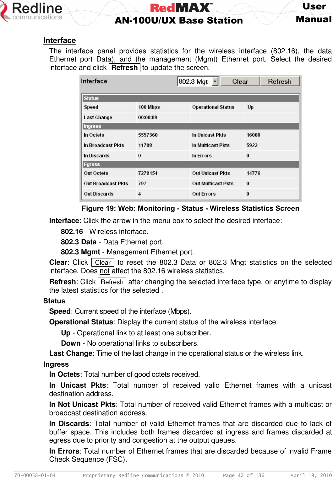
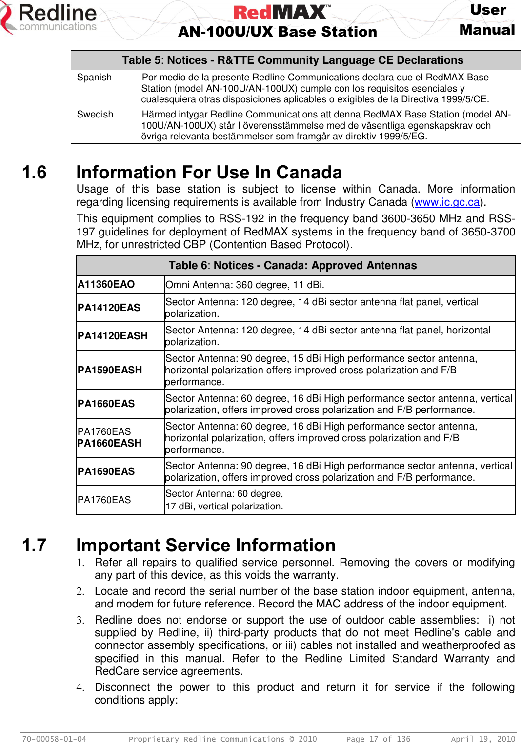
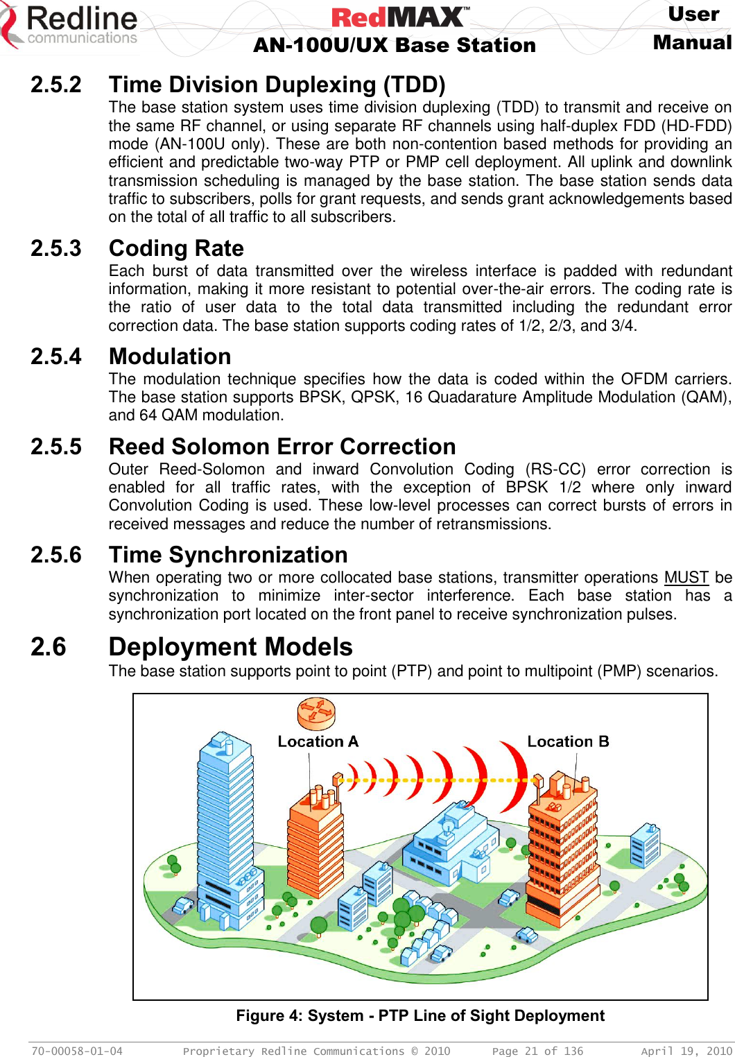
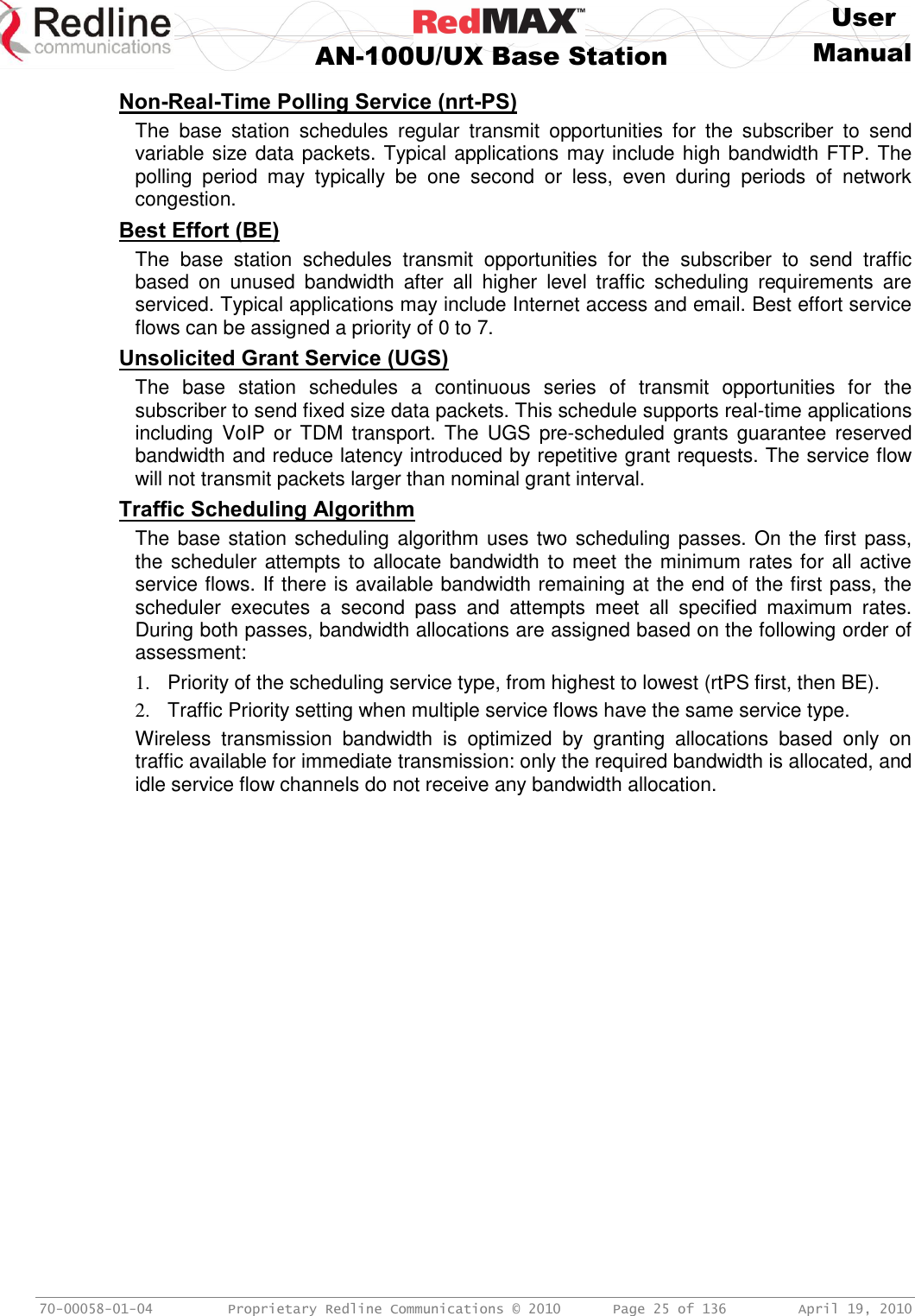
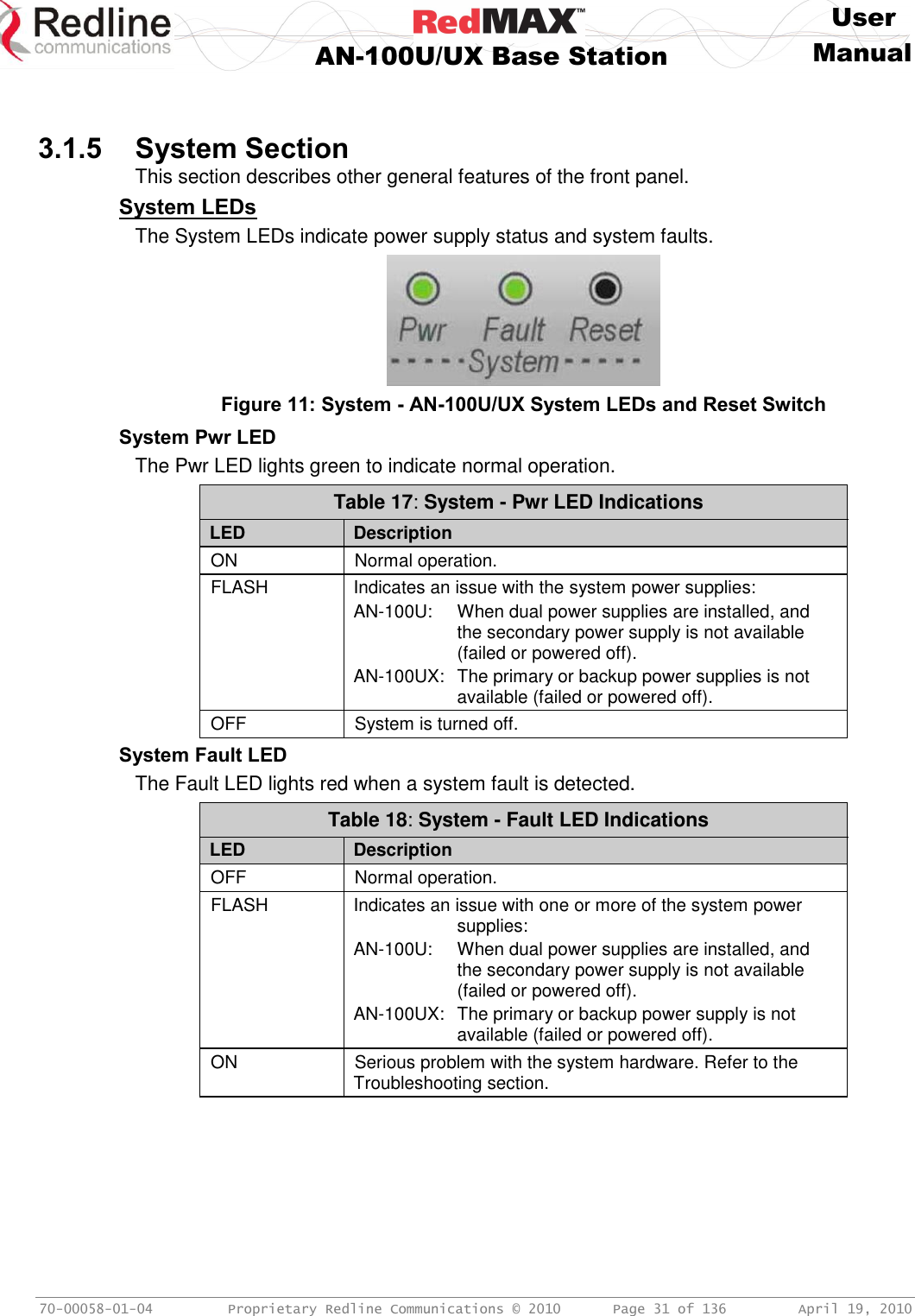
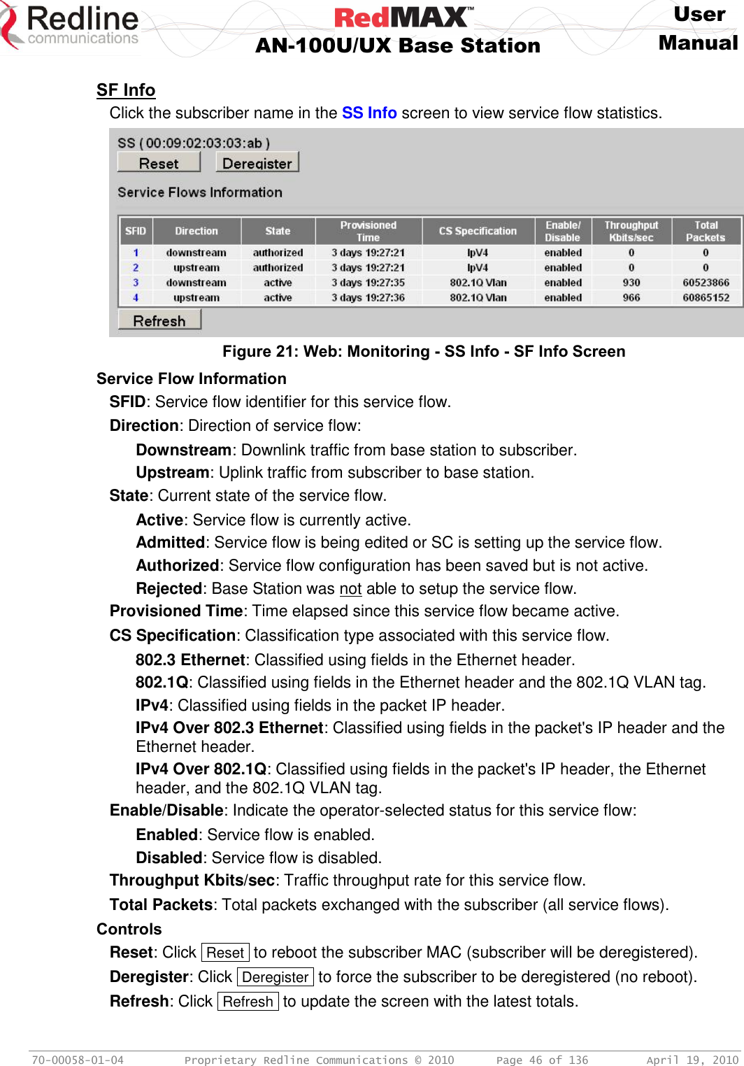
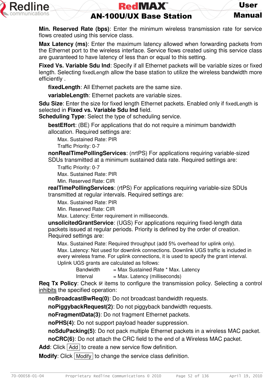
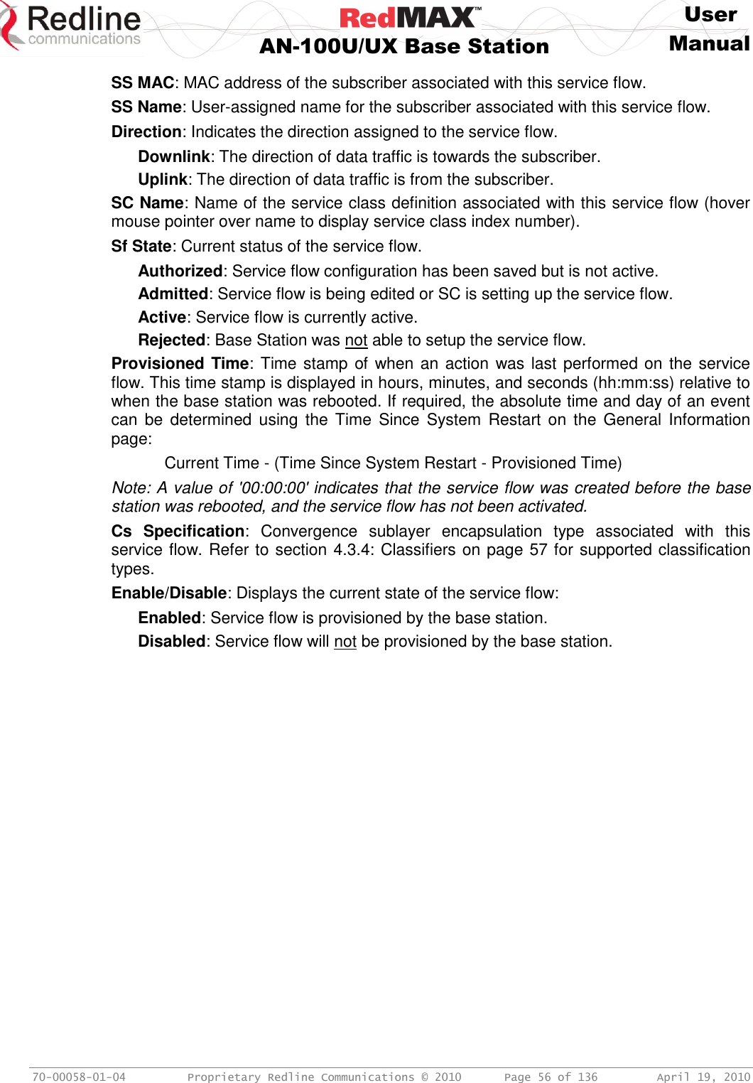
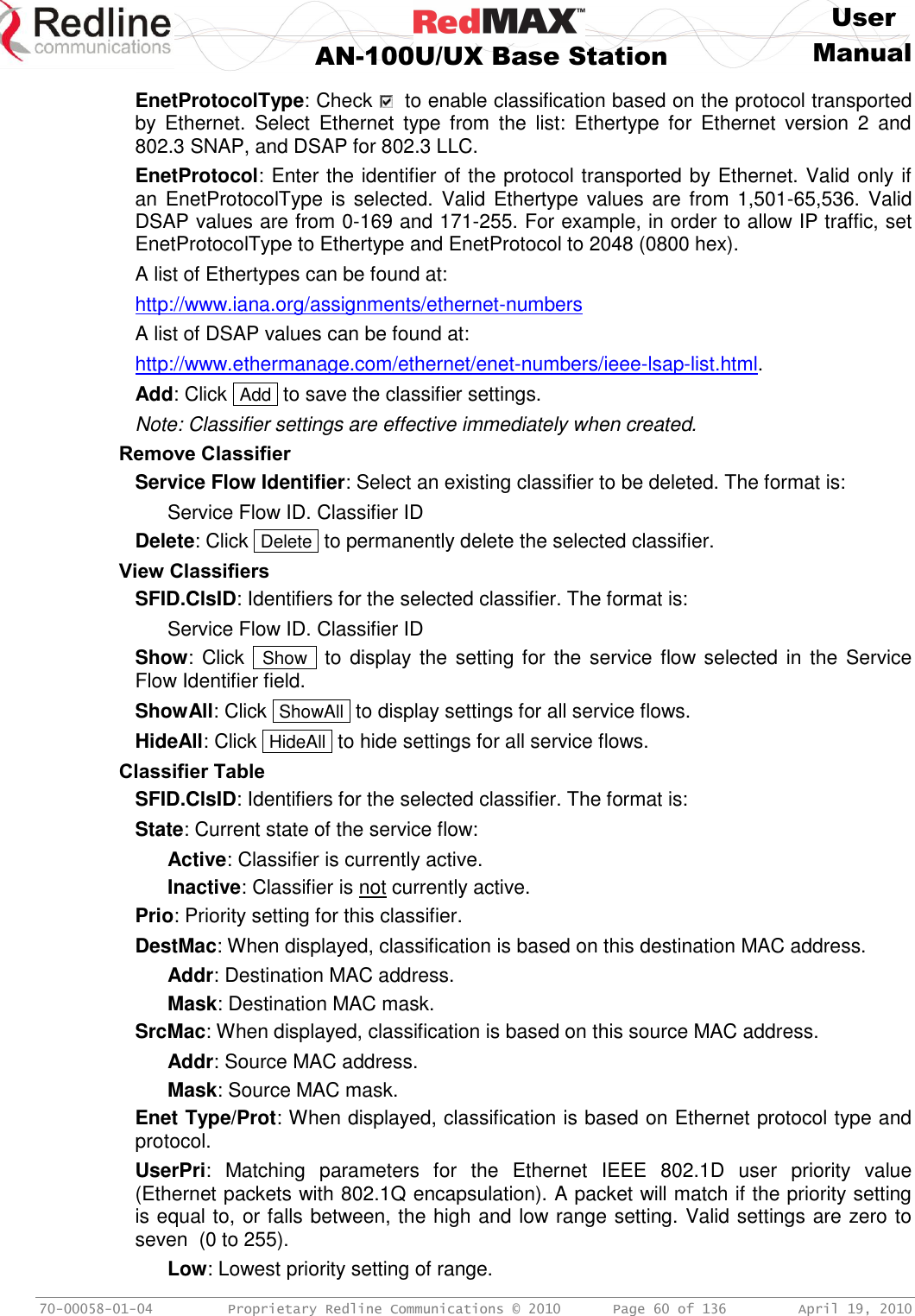
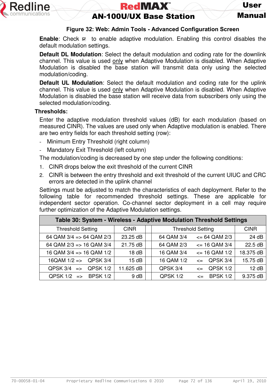
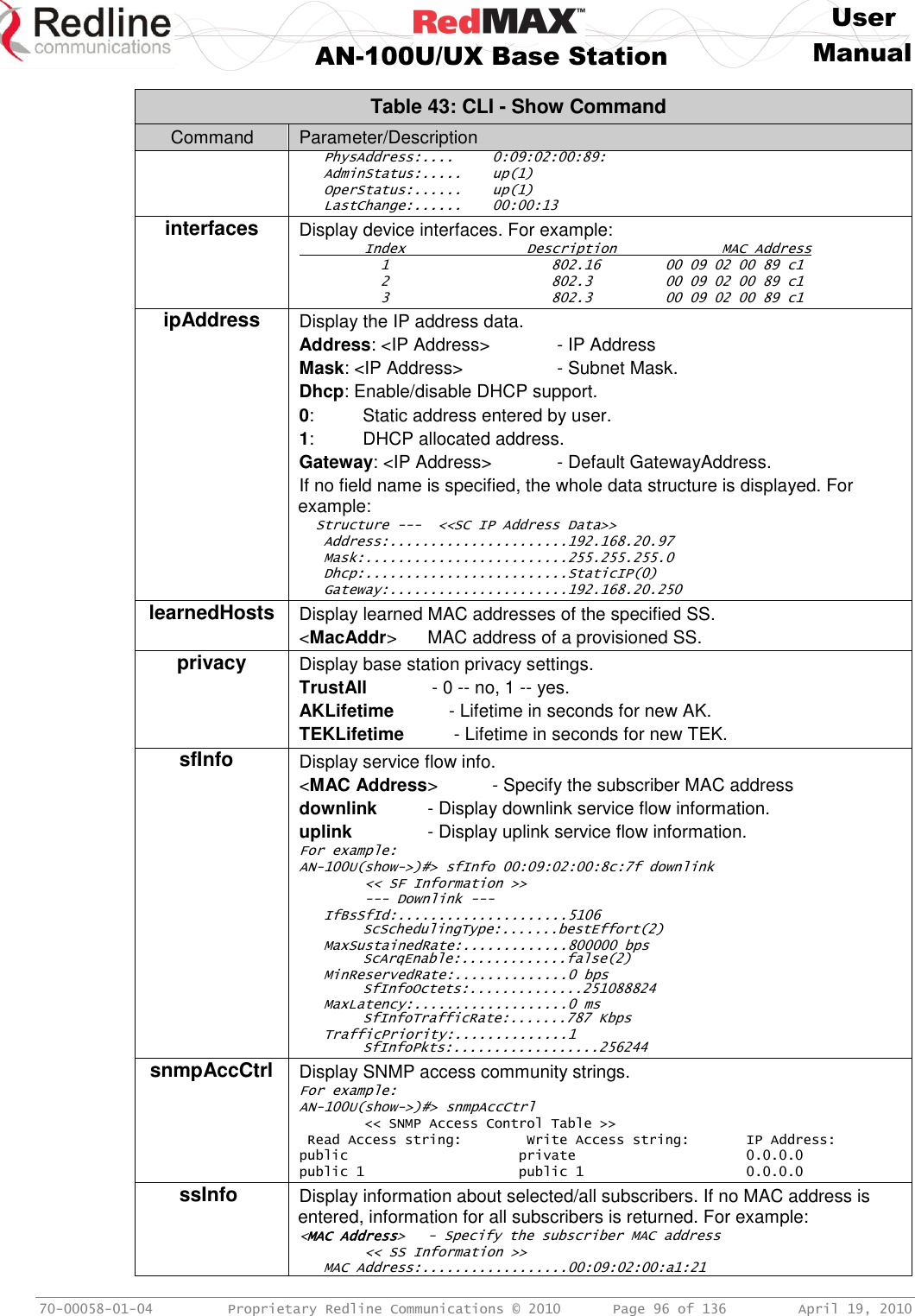
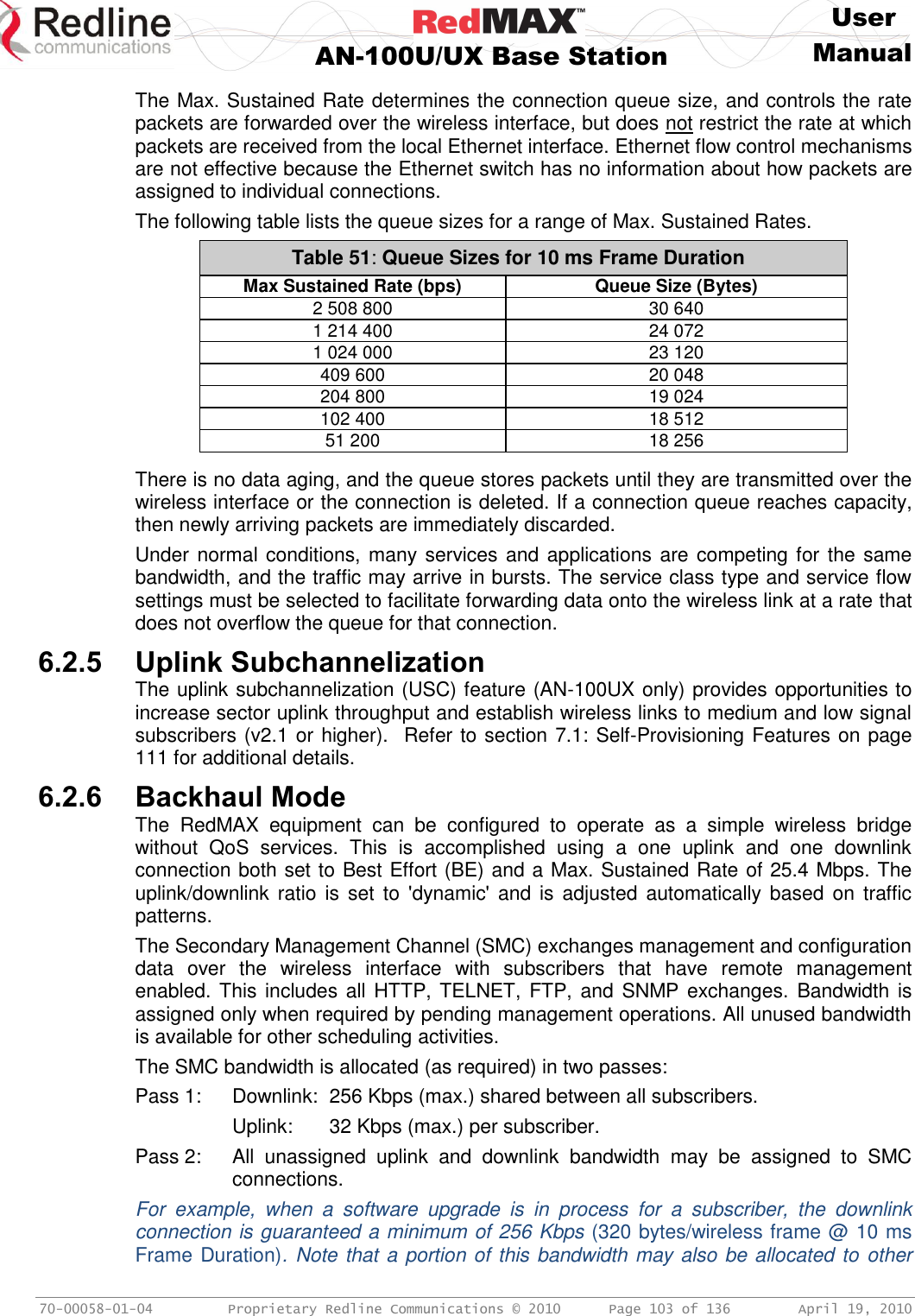
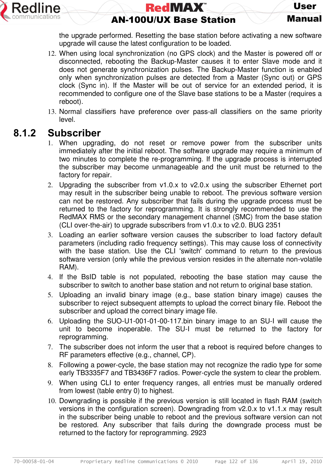
![User AN-100U/UX Base Station Manual 70-00058-01-04 Proprietary Redline Communications © 2010 Page 44 of 136 April 19, 2010 4.2.3 SS Info Click SS Information in the menu (left side of screen) to view system information, Ethernet address settings, and wireless statistics for active subscribers. Figure 20: Web: Monitoring - AN-100UX SS Info Screen SS Information Name: User-assigned name for subscriber. Click on the subscriber name (blue text) to view the service flows settings and statistics. IP: Secondary management channel (SMC) IP address for this subscriber. Mgm: Indicates if the subscriber can be managed over the wireless interface. Refer to the subscriber user manual for additional information about enabling remote management. yes: The subscriber supports remote management. no: The subscriber can not be managed remotely. DL Mod: Current modulation/coding setting for downlink channel. Displayed value is updated at one-minute intervals. UL Mod:Current modulation/coding setting for uplink channel. Curr CINR: The CINR value is continuously updated based on the last eight (8) frames. Min CINR: Lowest calculated CINR value since last reboot. Displayed value is updated at one-minute intervals. Max CINR: Highest calculated CINR value since last reboot. Displayed value is updated at one-minute intervals. Subchan: (AN-100UX only) Indicates subscriber uplink mode. In standard mode uplink transmission (full) each subscriber uses a reserved time slot and transmits data using all subcarriers. When uplink subchannelization (USC) is indicated, one or more subscribers may transmit simultaneously, each transmitting on designated groups of subcarriers. When USC is mandatory [m] for a subscriber, all service flows on that subscriber are forced to Best Effort, and the modulation is limited to BPSK 1/2 or QPSK 1/2. Refer to the full description of this feature in section 7.1: Uplink Subchannelization (AN-100UX only) on page 110. Important: Subscribers must be at software v2.1 or higher. full: Standard mode using all subcarriers (USC mode is not available). 1/2: 8 channel USC. 1/4: 4 channels USC. 1/8: 2 channels USC. 1/16: 1 channel USC.](https://usermanual.wiki/Redline-Communications/AN100UAE/User-Guide-1342304-Page-44.png)
![User AN-100U/UX Base Station Manual 70-00058-01-04 Proprietary Redline Communications © 2010 Page 45 of 136 April 19, 2010 [o]: USC optional (may be used for bandwidth optimization). [m]: USC mandatory to establish wireless link. UL CRC: Total number of CRC errors detected in transmissions from this subscriber. DL CRC: Total number of CRC errors reported by subscriber. UL RSSI: Uplink RSSI (Received Signal Strength Indicator) value (dBm) measured by the base station is continuously updated based on the last eight bursts. DL RSSI: Uplink RSSI value (dBm) measured by the subscriber is continuously updated based on the last sixteen (16) frames. Subscriber sends updated value at one-minute intervals. Tx Pow: Reported transmit power for this subscriber. Subscriber sends updated value at one-minute intervals. Dist: Calculated distance from base station to subscriber (kilometers). Refresh: Click the Refresh button to update this screen with the latest values.](https://usermanual.wiki/Redline-Communications/AN100UAE/User-Guide-1342304-Page-45.png)
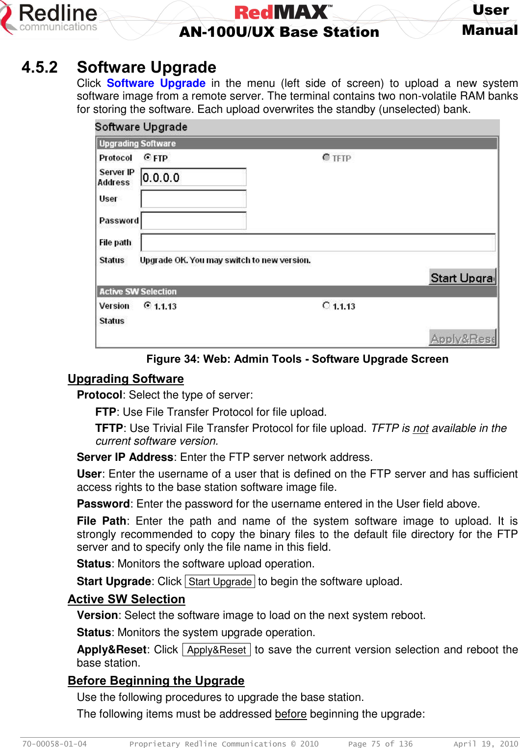
![User AN-100U/UX Base Station Manual 70-00058-01-04 Proprietary Redline Communications © 2010 Page 76 of 136 April 19, 2010 1. You must obtain the latest base station binary files. You must copy the binary files into the default file location for the FTP server. You can not specify a 'path' in the upgrade dialog. 2. The base station performs all software upgrades using an FTP server: a) The FTP server must be located on the network connected to an active Ethernet port (Data or Mgmt) on the base station. b) The FTP server must have a user defined as follows: username: target password: secret Upgrade Base Station 1. Start a Web browser session to the base station and login. The factory default settings are as follows: Login: admin Password: admin 2. Click Software Upgrade in the left-hand menu and make the following settings: Protocol: FTP Server IP address: [enter address of FTP server] User: target Password: secret File Path: [Enter binary file name -- including .bin extension] 3. Click Upgrade and wait for the base station to download and save the binary file. This process may take a few minutes. Progress is indicated in the Status field. The Status Screen displays 'Update OK' when the upgrade is complete. 4. In the Software Upgrade screen, Select the new version and click Apply&Reset to activate the new software. Click Yes in the confirmation dialog.](https://usermanual.wiki/Redline-Communications/AN100UAE/User-Guide-1342304-Page-76.png)
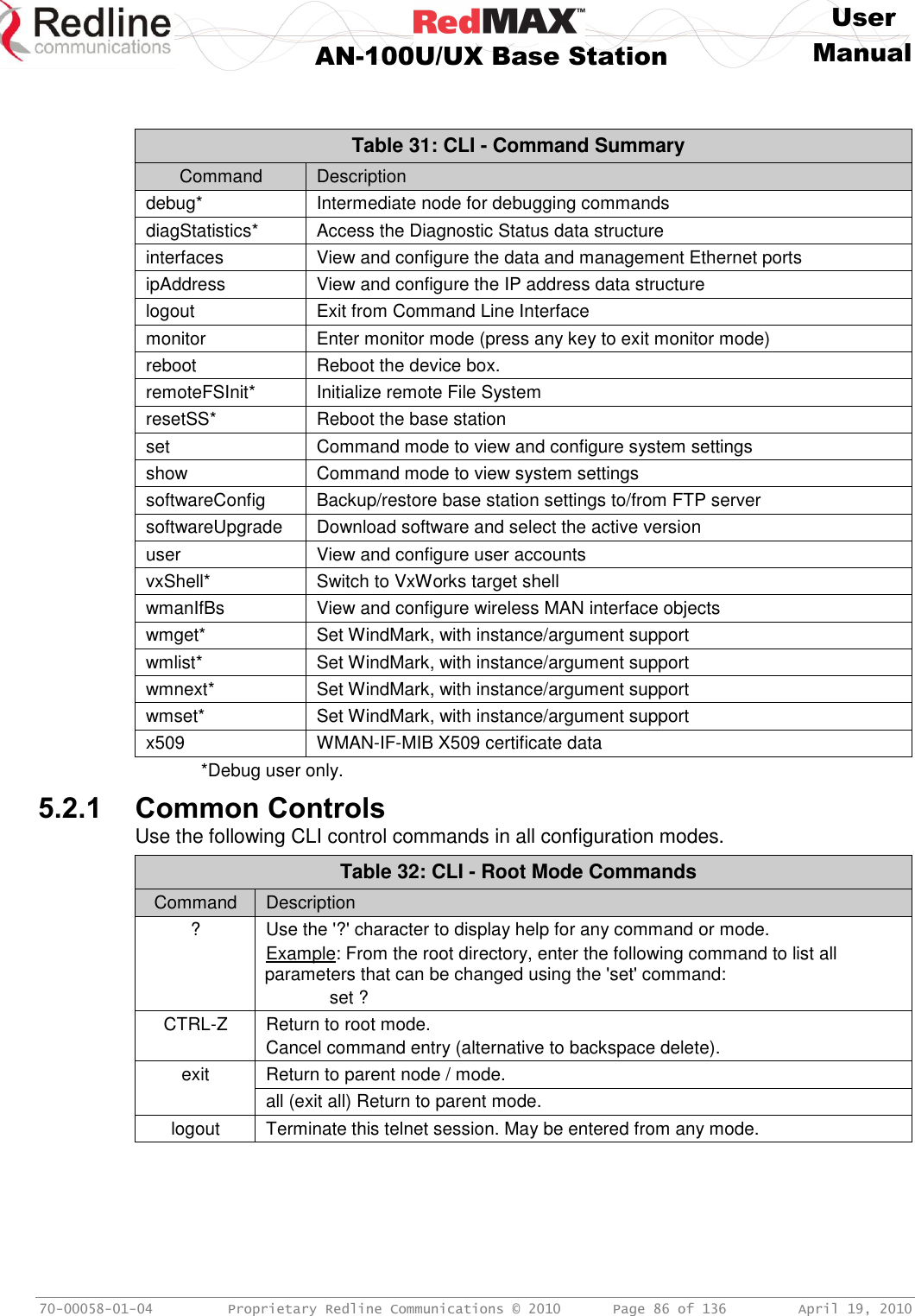
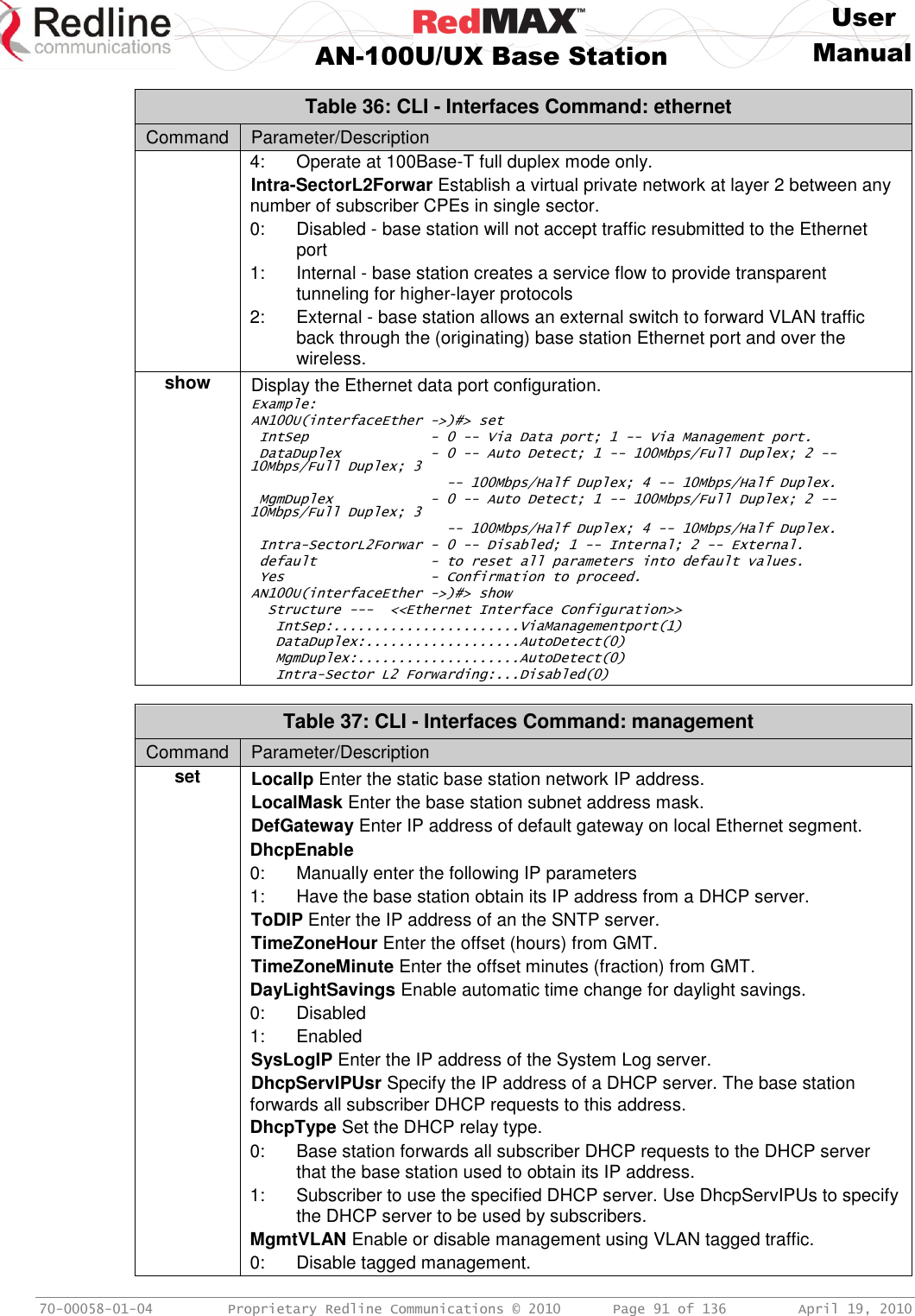
![User AN-100U/UX Base Station Manual 70-00058-01-04 Proprietary Redline Communications © 2010 Page 89 of 136 April 19, 2010 Table 35: CLI - Interfaces Command: advancedConfig (debug mode) Command Parameter/Description 2 - QPSK(3/4) 3 - 16QAM(1/2) 4 - 16QAM(3/4) 5 - 64QAM(2/3) 6 - 64QAM(3/4) GpsHoldoverStart Time in seconds after detecting GPS signal lost before entering holdover mode. Default is 30 seconds. GpsHoldoverEnd Time in seconds in holdover mode before reporting GPS signal lost. Default is 15 seconds. NoiseThreshold: Enter the maximum noise threshold (-123 to -65 dBm). If the measured noise (or interference) level exceeds this threshold, the base station stops transmitting until the noise level is lower than this threshold. Refer to 1.4: Deployment in the USA -- FCC Notices on page 13. ShowSsMac Choose information to show in log message. 0 - disable. Show SS name in log message. 1 -- enable. Show SS MAC address in log message. ReqBkEnd Enter the final backoff window size for contention during bandwidth requests. Must be in range [4-8] inclusive, and equal or greater than 'ReqBkEnd'; ReqBkStart Enter the starting backoff window size for contention during bandwidth requests. Must be in range [2-5] inclusive, and equal or less than 'ReqBkEnd'; RngBkEnd Enter the final backoff window size for initial ranging contention. Must be in range [4-8] inclusive, and equal or greater than 'RngBkEnd'; RngBkStart Enter the starting backoff window size for initial ranging contention. Must be in range [2-5] inclusive, and equal or less than 'RngBkEnd'; Th16Qam3/4To64Qam2/3 - CINR Value (dB) Up to 3 decimal places. Th16Qam3/4To16Qam1/2 - CINR Value (dB) Up to 3 decimal places. Th16Qam1/2To16Qam3/4 - CINR Value (dB) Up to 3 decimal places. Th16Qam1/2ToQpsk3/4 - CINR Value (dB) Up to 3 decimal places. Th64Qam3/4To64Qam2/3 - CINR Value (dB) Up to 3 decimal places. Th64Qam2/3To64Qam3/4 - CINR Value (dB) Up to 3 decimal places. Th64Qam2/3To16Qam3/4 - CINR Value (dB) Up to 3 decimal places. ThQpsk3/4To16Qam1/2 - CINR Value (dB) Up to 3 decimal places. ThQpsk3/4ToQpsk1/2 - CINR Value (dB) Up to 3 decimal places. ThQpsk1/2ToQpsk3/4 - CINR Value (dB) Up to 3 decimal places. ThQpsk1/2ToBpsk1/2 - CINR Value (dB) Up to 3 decimal places. ThBpsk1/2ToQpsk1/2 - CINR Value (dB) Up to 3 decimal places. ULModDefault Select the default modulation and coding rate for the uplink channel. This value is used only when Adaptive Modulation is disabled. When Adaptive Modulation is disabled the base station 0 - BPSK(1/2) 1 - QPSK(1/2) 2 - QPSK(3/4) 3 - 16QAM(1/2) 4 - 16QAM(3/4)](https://usermanual.wiki/Redline-Communications/AN100UAE/User-Guide-1342304-Page-89.png)
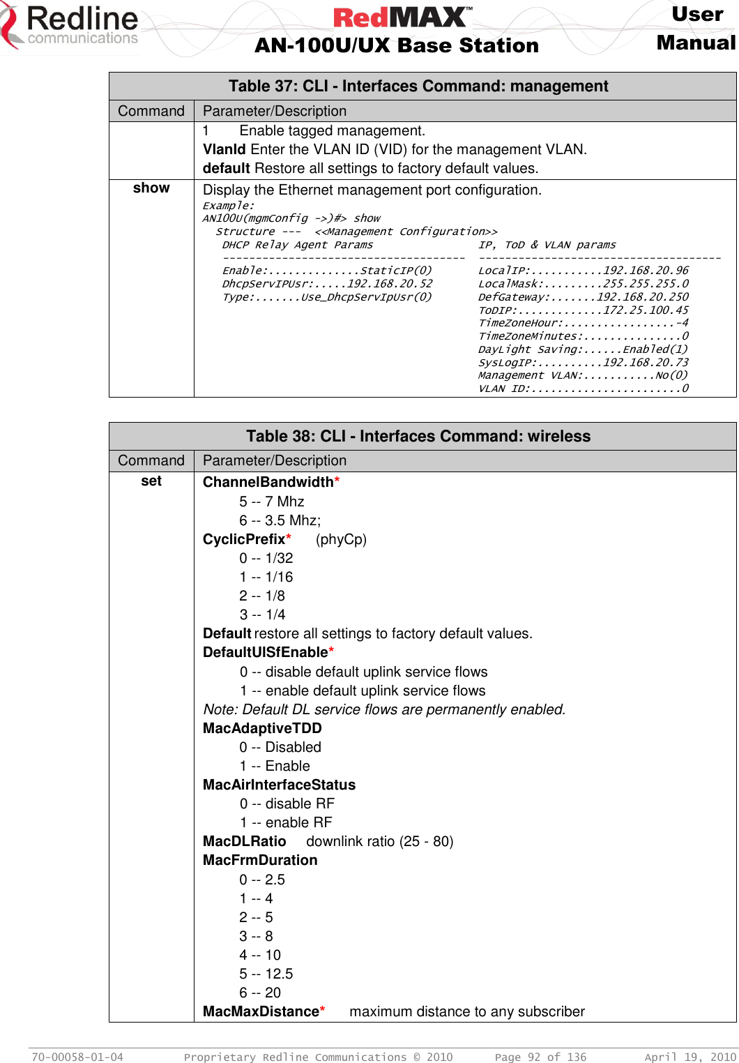
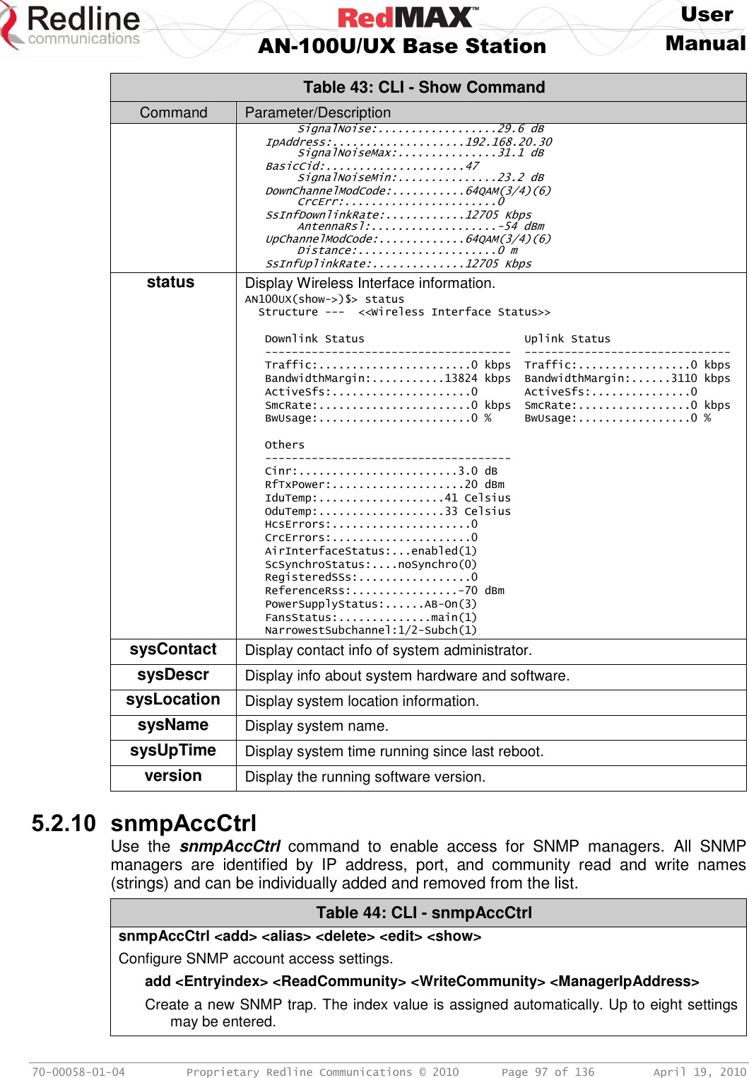
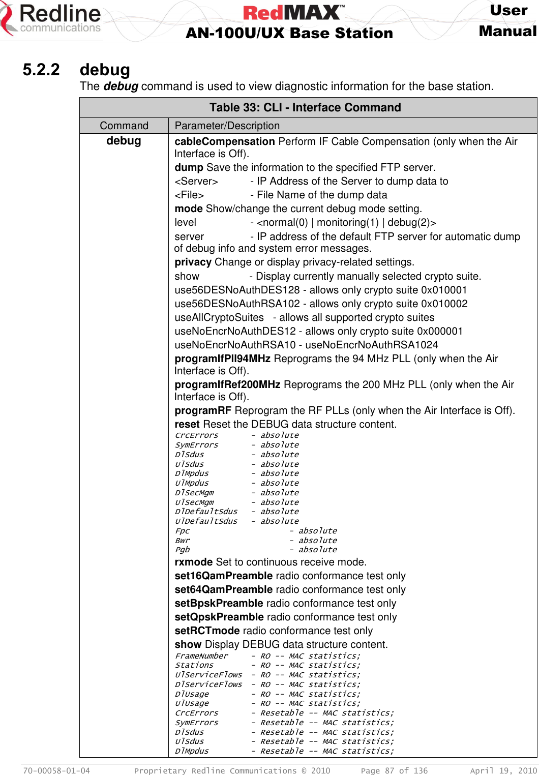
![User AN-100U/UX Base Station Manual 70-00058-01-04 Proprietary Redline Communications © 2010 Page 98 of 136 April 19, 2010 Table 44: CLI - snmpAccCtrl EntryIndex: Unique index number to identify this table entry. Read Community Name: The SNMP community name with read access. Write Community Name: The SNMP community name with write access. Manager Address: The IP address of the SNMP manager. alias <alias name> <replacement text> alias name: Text to be replaced replacement text: Text to substitute for alias delete <EntryIndex> [All | YesToAll] <EntryIndex> - Entry index number. All: Remove all the entries except the first one. YesToAll: Confirmation to remove all entries. edit <index> <ReadCommunity> <WriteCommunity> <ManagerIpAddress> EntryIndex: Unique index number to identify this table entry. Read Community Name: The SNMP community name with read access. Write Community Name: The SNMP community name with write access. Manager Address: The IP address of the SNMP manager. show << SNMP Access Control Table >> Index: Read Access string: Write Access string: IP Address: 1 public private 0.0.0.0 5.2.11 softwareConfig The softwareConfig command is used to load new software binary files on the base station. See section 4.5.2: Software Upgrade on page 75. Table 45: CLI - Software Upgrade Command Command Parameter/Description backup Save a backup copy of the base station settings on a remote FTP server. Server: IP Address of the FTP server. File: Use this name when saving the configuration backup file. Which: Specify the settings to be saved: 0 - Alternate configuration. 1 - Active configuration. For example: backup 192.168.20.100 BS_024-061108.cfg 1 <ENTER> You will be prompted by the FTP server to enter a valid username and password. restore Restore the base station settings using a backup copy previously saved on a remote FTP server. Server: IP Address of the FTP server. File: Use this name when saving the configuration backup file. Which: Specify the settings to be saved: 0 - Alternate configuration. 1 - Active configuration. For example: restore 192.168.20.100 BS_024-061108.cfg 1 <ENTER> You will be prompted by the FTP server to enter a username and password.](https://usermanual.wiki/Redline-Communications/AN100UAE/User-Guide-1342304-Page-98.png)
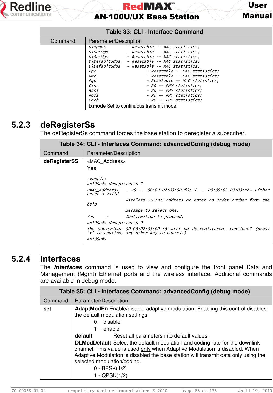
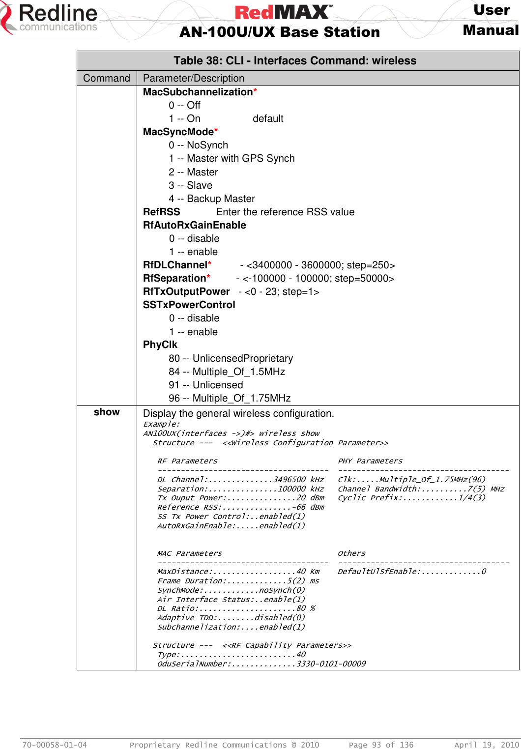
![User AN-100U/UX Base Station Manual 70-00058-01-04 Proprietary Redline Communications © 2010 Page 107 of 136 April 19, 2010 Q = (Min. Reserved Rate * Frame Duration / 8) * ( L + 1 ) 5. When packets have been transmitted in a wireless frame, the connection will not receive any bandwidth allocation during the next L-1 sequential wireless frames. This delay ensures the total throughput for the connection does not exceed the Max. Sustained Rate. Generally, the scheduler should be able to send data for an rtPS connection in every wireless frame when Max. Latency < 3 X Frame Duration. The following tests may be applied to validate that the desired latency can be achieved: The downlink latency requirements can be achieved only when both of the following conditions are true (where UL ratio may be from 0.15 to 0.75): i) Burst_Size_Bytes <= Q * (L+1) ii) Max. Latency >= Min [Frame Duration * 2, Frame Duration * (%UL ratio +1.5)] 6. Latency settings are ignored under the following condition: (Max. Latency < 3 * Frame Duration) The following formulas can be used to estimate the expected latency. Use the table below to determine the time required to transmit the data. LatencyMin = 2.4 ms + (TFrameRate * UL %) + (PDURef / 1000 * TRate) LatencyMax = LatencyMin + TFrameRate Table 53: Approximate Time to Transmit 1K Bytes @ Modulation/Coding Modulation & Coding Bytes/ OFDM Symbol Time to Send 1K Bytes (ms) CP=3.5 MHz CP=1/4 CP=3.5 MHz CP=1/16 CP=7 MHz CP=1/4 CP=7 MHz CP=1/16 64 QAM 3/4 108 0.74 0.64 0.37 0.31 64 QAM 2/3 96 0.83 0.71 0.42 0.35 16 QAM 3/4 72 1.1 0.94 0.56 0.47 16 QAM 1/2 48 1.7 1.4 0.83 0.71 QPSK 3/4 36 2.2 1.9 1.1 0.94 QPSK 1/2 24 3.3 2.8 1.7 1.4 BPSK 1/2 12 6.7 5.7 3.3 2.8 Example: Consider a connection with the following settings: Min. Reserved Rate = 409,600 bps Frame Duration = 10 ms Max. Latency = 65 ms L = RoundDown (55 ms / 10 ms) - 2 = 3 Q = (409,600 bps * 10 ms / 8) * (3 +1) = 2,048 bytes The scheduler assigns a quantum of 2,048 bytes (versus 512 bytes when latency is not specified). This allows up to four times the data throughput and related packets can be transmitted together in the same wireless frame. No bandwidth will be allocated to this connection for the next three consecutive wireless frames, and then the pattern repeats. The latency and bandwidth settings can be adjusted to ensure a 'best fit' for the application.](https://usermanual.wiki/Redline-Communications/AN100UAE/User-Guide-1342304-Page-107.png)
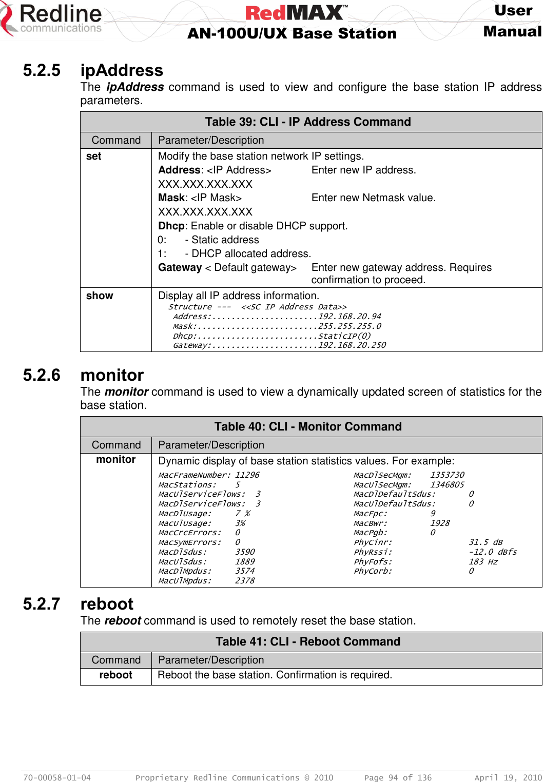
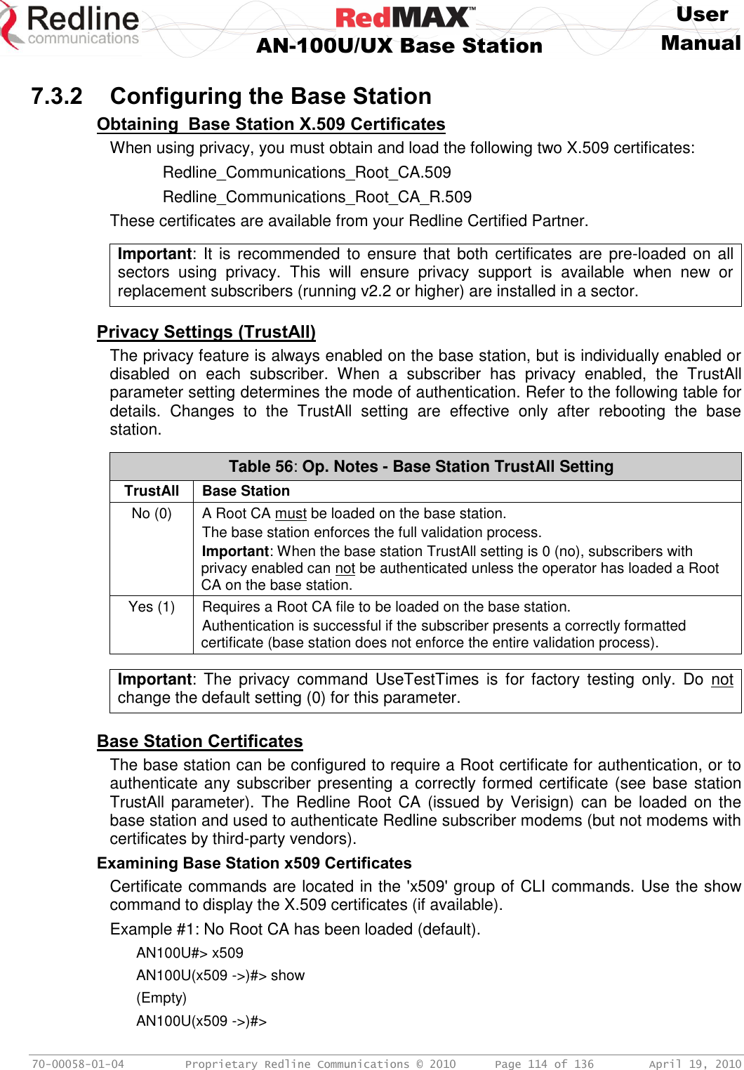
![User AN-100U/UX Base Station Manual 70-00058-01-04 Proprietary Redline Communications © 2010 Page 110 of 136 April 19, 2010 7 77 OOppeerraattiioonnaall NNootteess 7.1 Uplink Subchannelization (AN-100UX only) The uplink subchannelization (USC) feature provides opportunities to increase sector uplink throughput and establish wireless links to medium and low signal subscribers. This feature is available for all subscribers running software v2.1 or higher. Uplink Subchannels In standard mode, the base station maps timeslots during which a single subscriber is permitted to transmit using all data subcarriers. The USC feature organizes the 192 data subcarriers into 16 groups. During each USC timeslot, selected subscribers are scheduled to transmit on 1, 2, 4, or 8 subchannel groups (see following table). Table 54: Op Notes: Uplink Subchannelization Subchannel Group Assignment Designation in SSInfo screen 1/16 [o] 1/8 [o] 1/4 [o] 1/2 [o] Number of assigned subchannels 1 2 4 8 Concentrating the Tx power in subchannels provides a real gain of 7-10 dB in the subscriber uplink signal. This added gain enables use of higher modulations and can improve uplink throughput rates. Table 55: Op Notes: Subchannelization Uplink Bandwidth Improvement SS Info Label USC Disabled USC Enabled Full Up to 64 QAM Up to 64 QAM Optional BPSK, QPSK, 16 QAM 1/2 Up to 64 QAM Mandatory No Link BPSK 1/2 or QPSK 1/2 When USC is enabled, the base station classifies all subscribers based on the uplink signal quality (CINR, SNR, etc.). A column in the SS Info page identifies subscribers as 'full', 'optional', or 'mandatory', and indicates the number of assigned subchannels: Full: Subscribers able to establish a 16 QAM 3/4 or 64 QAM link without USC are tagged as 'full' and are not included in any USC scheduling. Optional: Subscribers with signal strength sufficient to establish BPSK or QPSK links without USC are tagged as 'optional'. These subscribers are candidates for traffic optimization. The increased gain available using the USC feature may enable these subscribers to transmit at modulations up to 64 QAM. Mandatory: Subscribers that can not establish a stable wireless link without benefit of the increased uplink gain provided by the USC feature are tagged 'mandatory'. These subscribers will only transmit during USC scheduled timeslots. Traffic from these subscribers is scheduled as Best Effort (regardless of service flow settings) and the highest available modulation is QPSK 1/2.](https://usermanual.wiki/Redline-Communications/AN100UAE/User-Guide-1342304-Page-110.png)
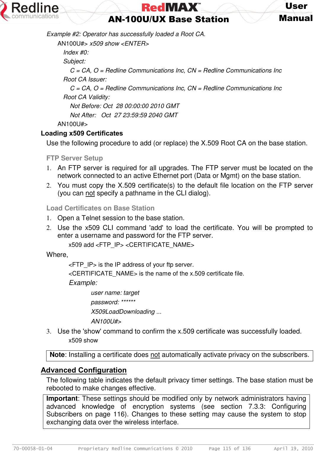
![User AN-100U/UX Base Station Manual 70-00058-01-04 Proprietary Redline Communications © 2010 Page 120 of 136 April 19, 2010 7.6 RedMAX Backhaul Application The RedMAX equipment can be configured to operate as a PTP backhaul link to provide backhaul services to a remote location (e.g., RedMAX PMP network). This can reduce capital and operational expenses (training, spare parts, etc) when compared to purchasing other models or manufactures equipment to provide this service. There are no hardware, software, or configuration changes required for any RedMAX subscriber or base station used for backhaul operations. 7.6.1 Base Station Configuration There are three specific configuration settings required to enable the RedMAX base station for backhaul operation (no configuration change is required for the subscriber). Service Class Create one service class with the following settings: SC Name: Backhaul Scheduling Type: BE Traffic Priority 0 Max Sust Rate 25400000 Service Flows Click Service Flows in the menu (left side of screen) and create two service flows with the following settings. Enter the following settings for the upstream service flow. SS Name: [subscriber name] Direction: upstream SC Name: Backhaul Cs Specification: 802.3 Ethernet. Enter the following settings for the downstream service flow. SS Name: [subscriber name] Direction: downtream SC Name: Backhaul Cs Specification: 802.3 Ethernet. Classifiers Click Classifiers in the menu (left side of screen) and enter the same settings for the upstream and downstream service flows: DestMacAddr: Check to enable field. Enter a value of all zeros (00:00:00:00:00:00). DestMacMask: Enter a mask of all zeros (00:00:00:00:00:00). Synchronization Click Wireless Interface in the menu (left side of screen) and select the following settings in the MAC Parameters section of the page: Adaptive TDD: Check box to activate dynamic uplink/downlink setting. A log message is created when Adaptive TDD is enabled and disabled. This feature is enabled only when Synchronization Mode = No Sync. Synchronization Mode: No Sync The synchronization function must be disabled to enable use of the Adaptive TDD.](https://usermanual.wiki/Redline-Communications/AN100UAE/User-Guide-1342304-Page-120.png)
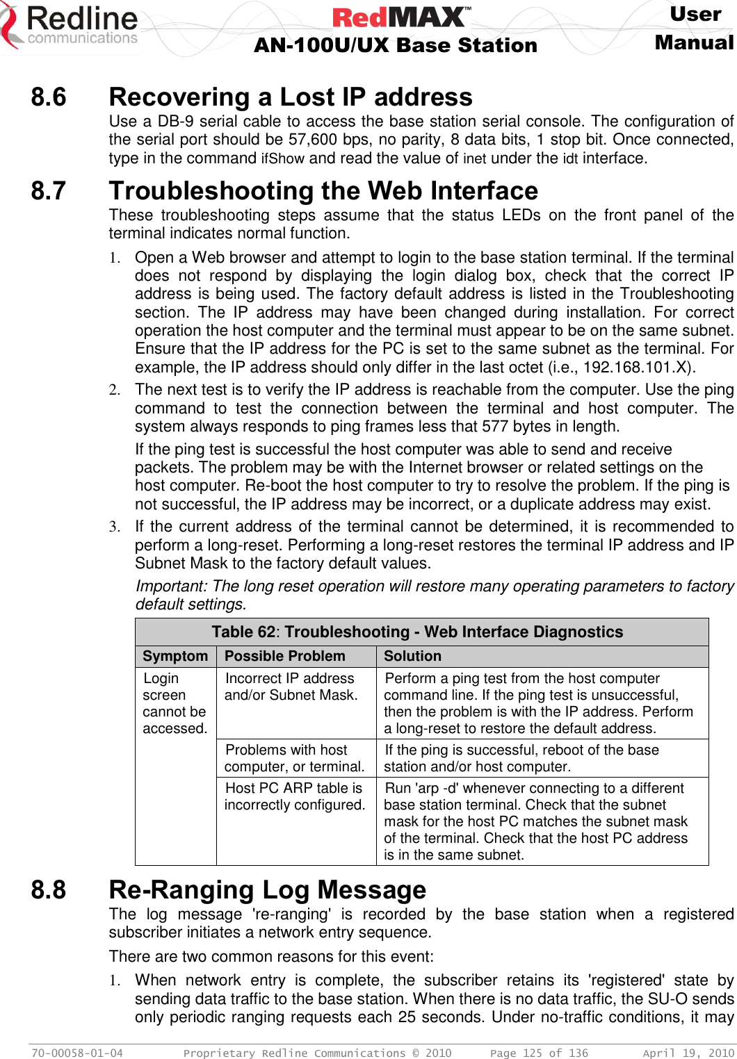
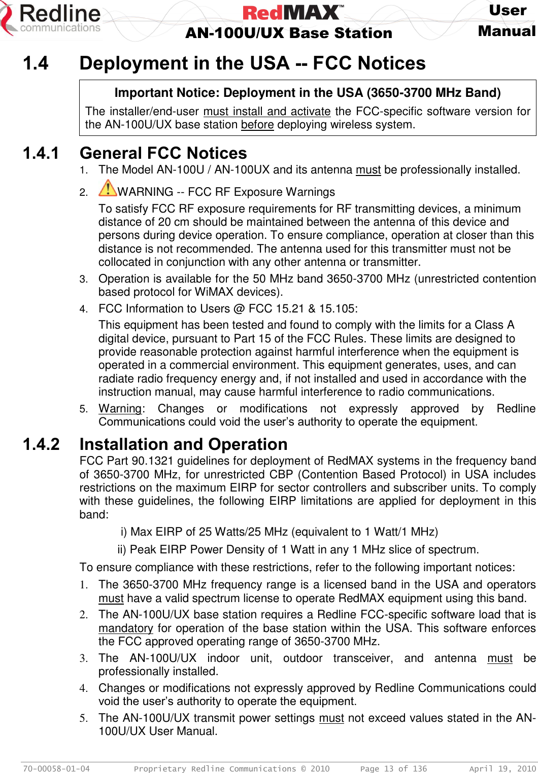
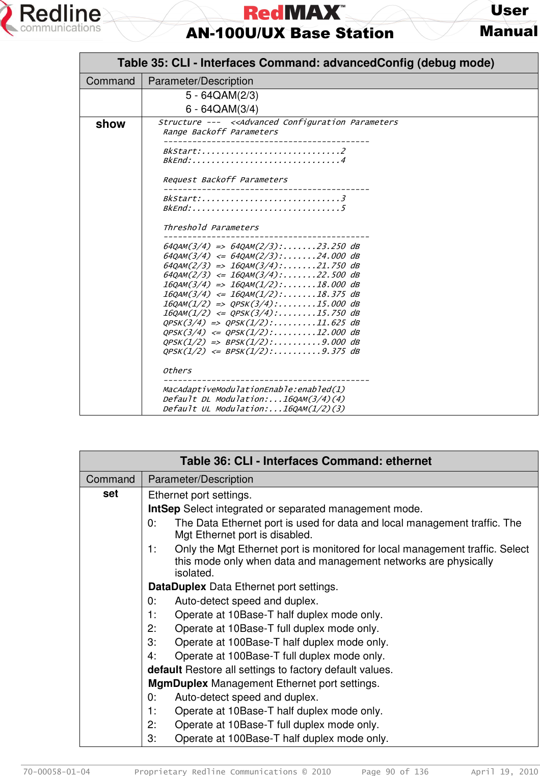
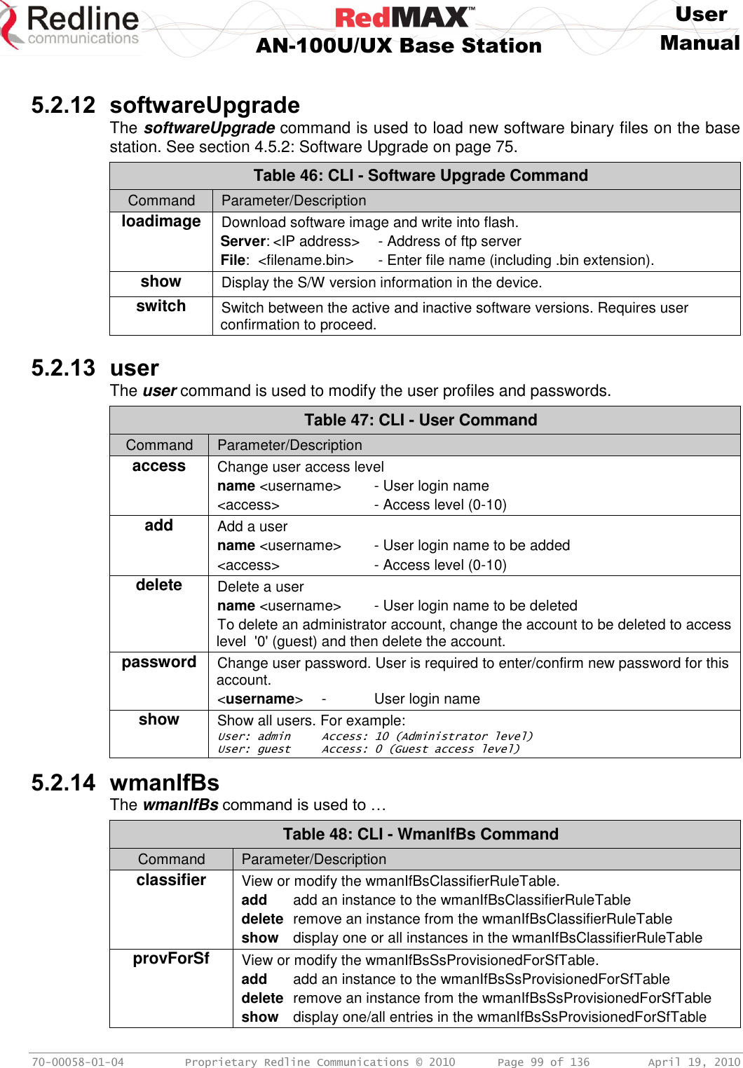
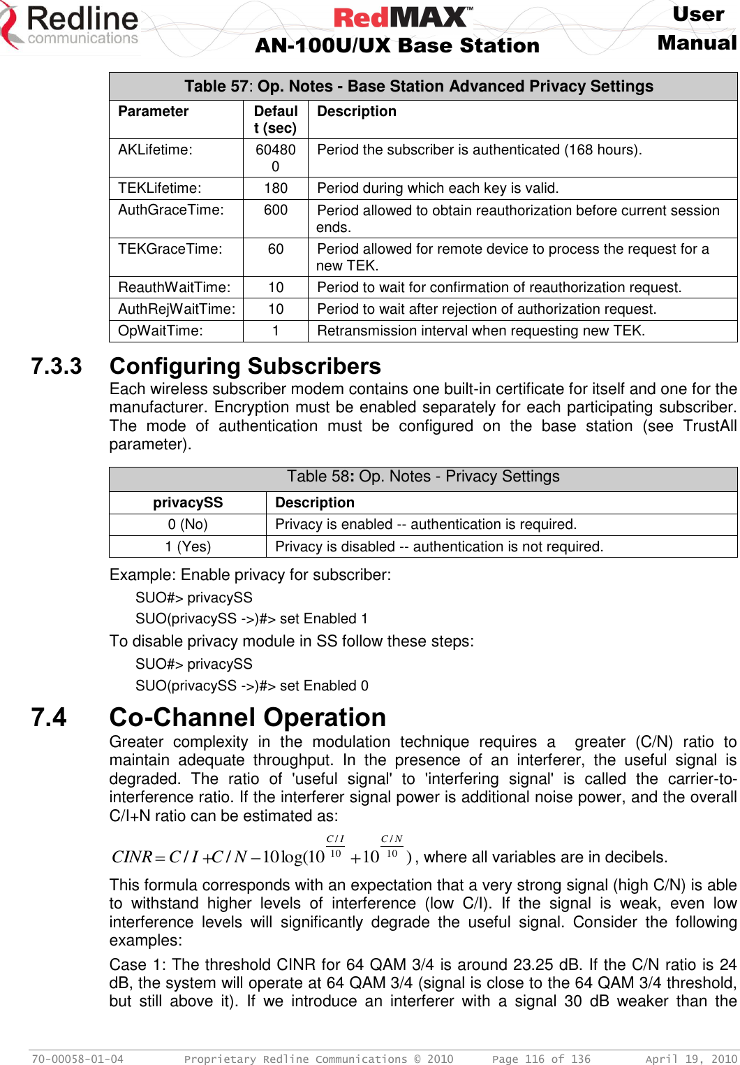
![User AN-100U/UX Base Station Manual 70-00058-01-04 Proprietary Redline Communications © 2010 Page 124 of 136 April 19, 2010 8.4 Front Panel Diagnostics Figure 43: Diagnostics: AN-100UBase Station Front Panel View 8.4.1 System LEDs The front panel of the terminal includes a number of LEDs to monitor operation of the system and assist troubleshooting. Refer to section 3: Physical Description on page 26. 8.4.2 Console Port The front panel includes the Console port. Use the CLI commands to interrogate the base station status and program most system settings. 8.4.3 System Reset Switch Throughout this section, reference is made to the reset switch, which is a micro-switch recessed in the front panel in the system block. Use a small narrow object, such as a paper clip, to access the switch. Depressing the reset switch for less than five seconds activates a short-reset (equivalent to power-cycle). Statistical values are reset. Depressing the front panel reset switch for more than five seconds activates a long-reset. A long-reset reloads the factory defaults for the IP Address, IP subnet mask, password, and statistical values are reset. 8.5 Detecting Channel Interference at Startup Following a power-cycle or reboot, the base station monitors the RF Channel to detect interference on the uplink channel. The transceiver is set to receive mode and the PHY is programmed to receive a long preamble from a WiMAX base station. If no preamble is detected during the one-second interval, the channel is considered free of interference from other WiMAX equipment. If a long preamble is received, the base station continues to monitors the channel for an additional three seconds. If an 802.16d DL-Map is received, the following message will be entered into the event log: WARNING: RF Channel Conflict with [BS Id] This message in the event log indicates that another base station has been detected using the following RF-PHY characteristics: - Same DL channel frequency as the UL channel frequency of this SC - Same Cyclic Prefix - Same channel size (i.e., 7 MHz) If a long preamble was received, but no DL-Map was detected, the following message will be entered into the event log: WARNING: Unknown Interference was detected on the UL channel This second message does not necessarily indicate interference from another base station, and may be the result of cross-interference from subscribe stations.](https://usermanual.wiki/Redline-Communications/AN100UAE/User-Guide-1342304-Page-124.png)