Redline Communications AN50 Access Node User Manual AN 50 v121
Redline Communications Inc. Access Node AN 50 v121
Contents
- 1. users manual 1
- 2. users manual 2
- 3. installation manual
installation manual
AN-50 User Manual
12/51
Redline Communications …..solving the first mile challenge.
5. AN-50 Terminal Installation
This section describes the easy steps to follow to install the AN-50 terminal and
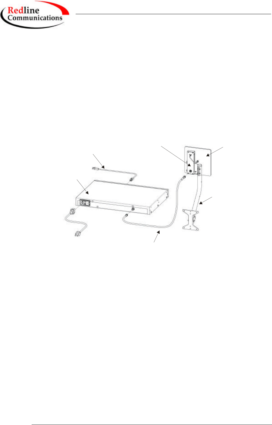
associated equipment. Figure 3 illustrates the three primary cables that are
required to complete the installation including; Power, IF and CAT 5 (not
included). The power cord connects to a standard North American 120 VAC
power outlet, the IF cable connects the terminal (located indoors) to the
transceiver (located outdoors), and the CAT 5 which connects the terminal to a
switch or router for interface to the core network.
Terminal
CAT 5 Cable
AC Power
Chord
IF Cable
Transceiver
Antenna
Pole and
Mount
Flat Plate
Antenna
Figure 3 AN-50 installation.
The terminal is for indoor installation only while the transceiver and antenna are
mounted externally. The principal steps in installation are:
1. Conduct a general site survey
2. Install the antenna
3. Run the IF cable
4. Install the terminal
Each step is addressed in more detail below.
5.1. General Site Survey
The first step in installing the AN-50 system is to conduct a general site survey.
Although the installation steps are relatively straightforward, they do involve
some construction and electrical work, which can be best performed by
professional installers.

AN-50 User Manual
13/51
Redline Communications …..solving the first mile challenge.
The following site survey steps should be followed:
Determine the optimum location: The first key step in the deployment exercise
is to determine and identify building candidates that can be used to support the
PTP link. A critical parameter to consider is the range at which the two terminals
are required to operate. Range performance is determined by empirical formulas
that consider a number of equipment and environmental factors described in
Section 8 of this manual. Ensure that the installation sites meet the above range
performance requirements before moving to the next step. There are a number of
cell planning tools available in the market today, which make use of topographic
data to help with the cell planning.
Obtain a copy of the facility blueprints and verify their accuracy. The
installation process will require penetrating the building to run the IF cable
between the outdoor and indoor units. In this regard, it is imperative that the
blueprints of the building are up to date and accurate.
Identify a Clear Line of Sight Path. For maximum performance, it is
recommended to mount the antenna in a location where there is line of sight to the
remote terminal. If possible, the antenna should be positioned such that there is
maximum clearance within the first Fresnel zone of the direct path. Refer to
Section 8 for a full description of Fresel zone clearance and its impact on signal
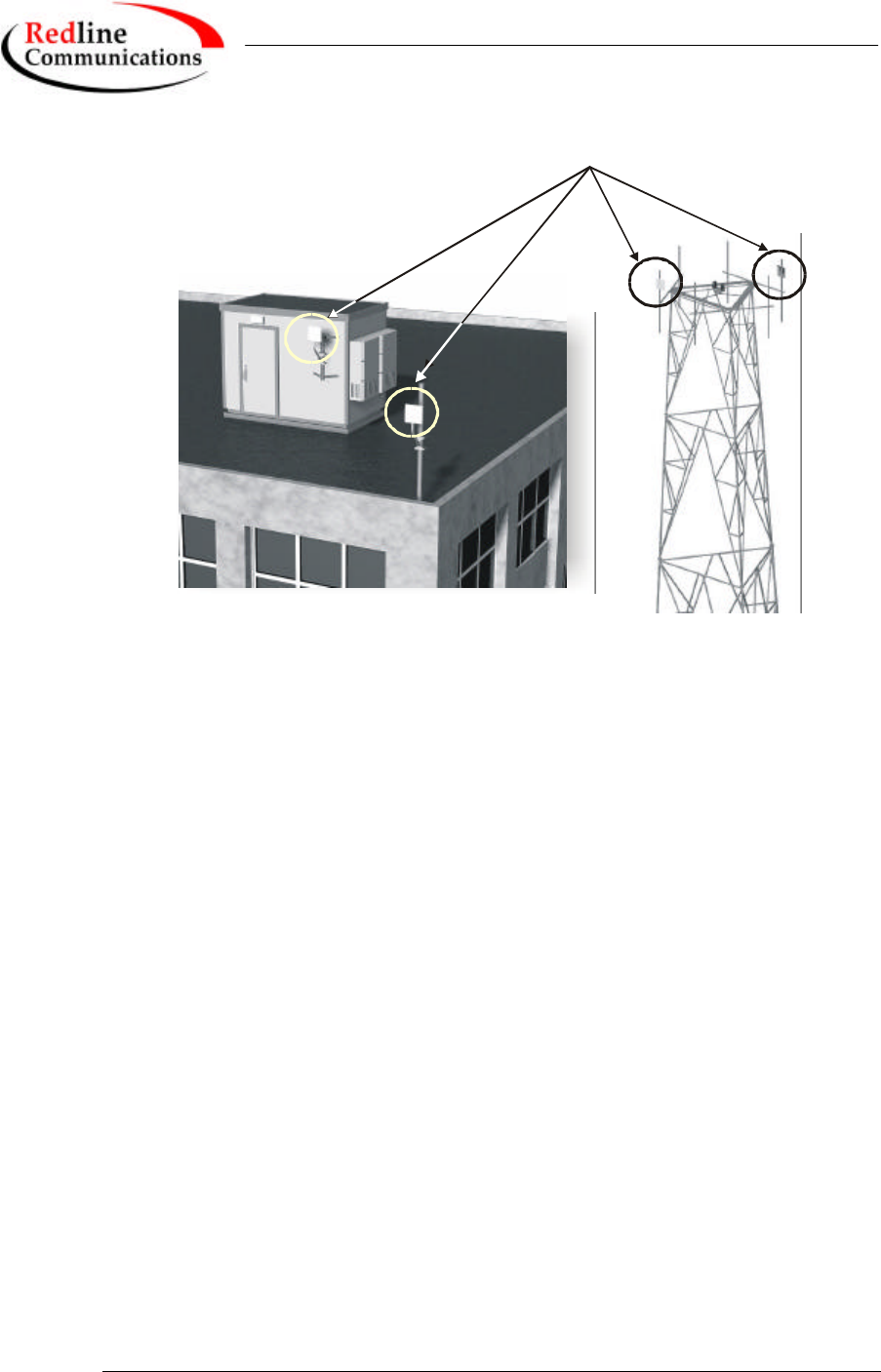
propagation. The best means of achieving Fresnel zone clearance is to mount the
antennas as high as possible, on either a tall building or tower, as shown in Figure
4. Although the system is designed to operate in obstructed line of sight (NLOS)
conditions, as a result of the OFDM technology it incorporates, LOS deployments
provide much greater throughput capability.
AN-50 User Manual
14/51
Redline Communications …..solving the first mile challenge.
Transceiver
Deployments
Figure 4 Antenna deployment options.
Identify potential sources of RF interference. Measure for any possible RF
interference on the roof-top or tower by utilizing a RF power meter or spectrum
analyzer. RF interference arises from any other wireless system operating within
the same frequency band of the AN-50. Note that the AN-50 can operate in any
one of the four channels designated for UNII band, therefore, there is some
flexibility in addressing or avoiding the interference should other transmitters, in
relatively close proximity, pose a problem.
Verify the location of access points. With the remote terminal transmitting, use a
spectrum analyzer to ensure there is adequate signal strength arriving at the
candidate location for the antenna.
5.2. Installing the Antenna
Once the site survey has been completed, and the exact location of the antenna
identified, the next step is to mount the AN-50 transceiver/antenna onto either a
building structure or pole. The antenna and mounting brackets have been designed
to withstand strong winds (see specifications at the end of this user guide). It is
imperative that all bolts and nuts are securely fastened to avoid any movement
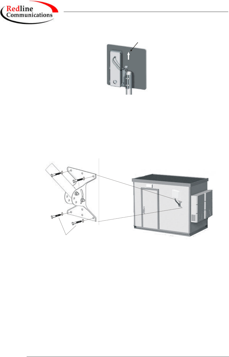
that could introduce misalignment. Note that there is an arrow on the back of the
antenna, which must be pointing upwards to indicate proper orientation when the
antenna is deployed.
AN-50 User Manual
15/51
Redline Communications …..solving the first mile challenge.
Orientation
Arrow
For building mounts, ensure the surface to which the mounting bracket will be
attached is flat and vertical (use a level). Install the bracket using four lag screws,
with washers. There are two center holes that can be used to mount the bracket
onto a 2x4 stud. Make sure the surface to which the bracket is attaching is
structurally sound and can withstand the specified wind loading.
Lag Screw
and Washer
Figure 5 Mounting the antenna on a building structure.
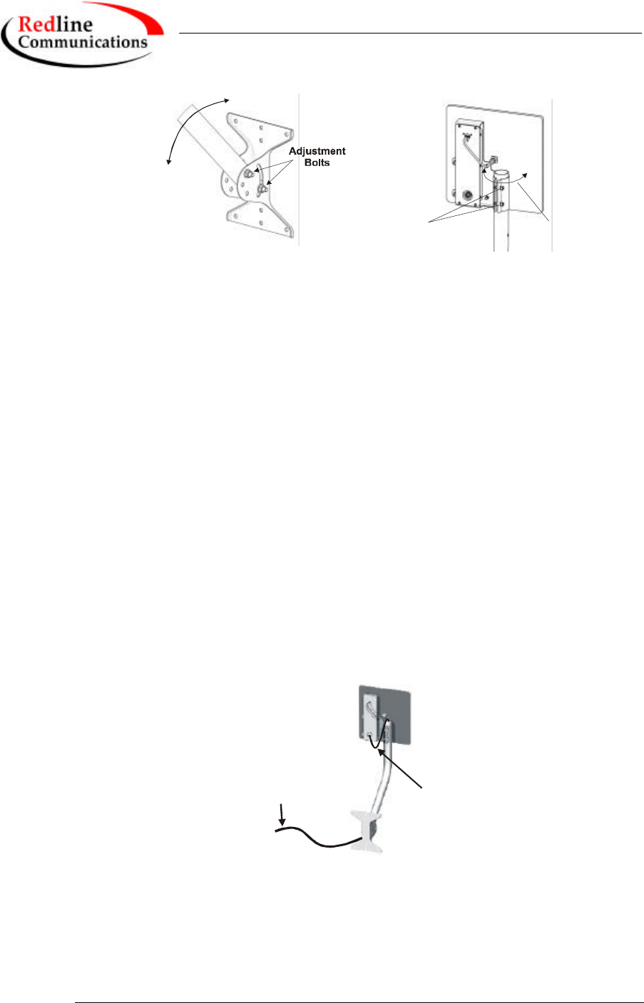
Once the antenna is mounted, it has to be aligned in both the azimuth and
elevation planes. The elevation alignment is accomplished by loosening the two
bolts attached to the mounting bracket, as shown in Figure 6, and slanting the pole
until the antenna is aligned in elevation towards the remote terminal. The azimuth
alignment is achieved by loosening the two bolts on the antenna bracket, and
rotating the antenna until alignment is achieved.
AN-50 User Manual
16/51
Redline Communications …..solving the first mile challenge.
Elevation
Adjustment
Adjustment
Bolts
Azimuth
Adjustment
Figure 6 Aligning the antenna.
Note that the antenna can also be mounted onto another pole separate from the
one supplied with the system. Contact Redline for different antenna mounting
options.
5.3. Running the IF Cable
The system is equipped with a 100 foot of RF cable to interconnect the transceiver
and terminal. The following steps define the cable installation:
1. Run the cable through the antenna pole as shown below. Add extra cable
length to produce a drip-loop, as shown, to prevent water from
accumulating onto the connector. The IF cable is equipped with 75 ohm
F-type connectors at both ends, however, it is important to note that one
end of the cable is designated for outdoors, as it is a specialized weather
proof design, while the other end is to be connected to the indoor terminal
unit. A label is attached to one end of the cable to clearly indicate the
connector that is intended for outdoors. Make certain the ‘Outdoor’ label
is attached to the end of the cable that you plan to connect to the radio.
IF
Cable
Cable
Drip-Loop
2. Connect the F-type male connector from the cable to the female connector
attached to at the bottom of the transceiver. Note the connector at the top
end of the transceiver is connected via cable to the antenna itself.
AN-50 User Manual
17/51
Redline Communications …..solving the first mile challenge.
3. Run the cable into the building by drilling a hole in the wall, where you
want the RG-6 to enter, or through an existing conduit. Local codes
require, at a minimum, that a ground cable be used, with a grounding
block installed as close as possible to the point of cable entry. An
optional lightning arrester may be used to protect the terminal and other
indoor equipment from sudden electrical surges. There are a variety of
choices for lightning arresters – it is recommended to use a professional
installer to determine the optimized solution.
4. Once inside the building, connect the cable to the F-type female
connector located on the back of the terminal.
5.4. Install the Terminal
Once the IF cable is connected, the terminal is ready to be installed and
configured. The first step is to connect a CAT 5 cable from the Ethernet port to
the host IP appliance. Note a CAT 3 cable can be used if the terminal operates in
10BT mode (10 Mb/s data rate). However, even with 10BT connections today, it
is recommended to use CAT 5 cabling initially in anticipation for the increased
speed in the future. As noted previously, the data rate is determined automatically,
depending on the type of IP device connected to the system.
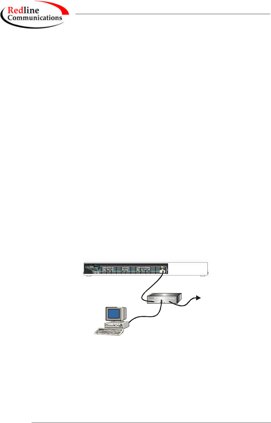
If the terminal is used for connection to a core network, then the IP appliance is
likely to be a router or switch as shown in Figure 7. In this configuration, a cross-
over Ethernet cable is required.
Third Party
Switch/Router
To Core
Network
Host
Computer
Figure 7 AN-50 connected to switch/router
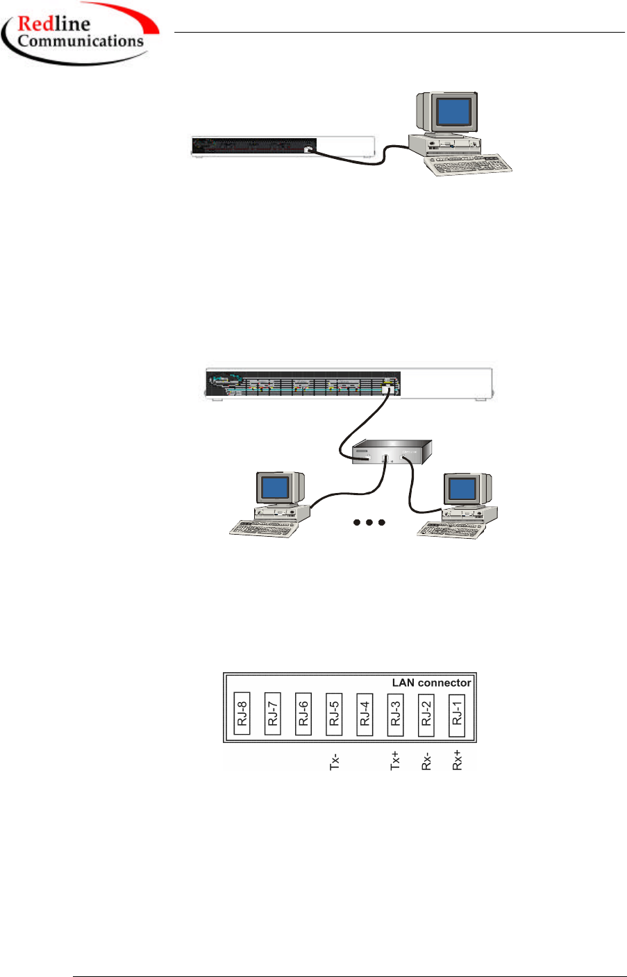
For the remote terminal, the AN-50 may be connected directly to the host
computer, as shown in Figure 8. In this configuration, a straight-through Ethernet
cable is required.
AN-50 User Manual
18/51
Redline Communications …..solving the first mile challenge.
Host
Computer
Figure 8 AN-50 connected to host computer.
The remote terminal may also be connected to a simple hub, for distribution to
several computers in a local network configuration, as shown in Figure 9. If the
terminal is connected to simple, hub, then a cross-over cable is required.
Third Party
Hub
Host
Computer Host
Computer
Figure 9 AN-50 connected to a hub.
Figure 10 provides an illustration of the pin-out designation for the AN-50 LAN
interface, to help you establish other implementations that are not addressed in
this manual.
Figure 10 AN-50 LAN Ethernet Port pin-out.
Now connect the AC cord to the 120 VAC outlet and turn the terminal on using
the toggle switch at the rear of the unit. The system “Pwr” LED should illuminate
green to indicate proper power to the unit. If this LED is not on and/or the “Fault”
LED illuminates red, then there is a problem with the unit. Refer to the
diagnostics section, Section 7 on page 31, for further details on how to address
system faults. The system is now ready to be configured.