Redline Communications AN50 Access Node User Manual AN 50 v19
Redline Communications Inc. Access Node AN 50 v19
UserManual.wiki
>
Redline Communications
>
AN50 User Manual
>
users manual 1
Contents
1.
users manual 1
2.
users manual 2
3.
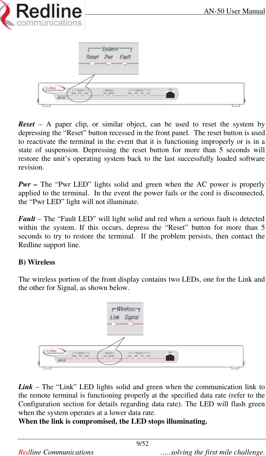
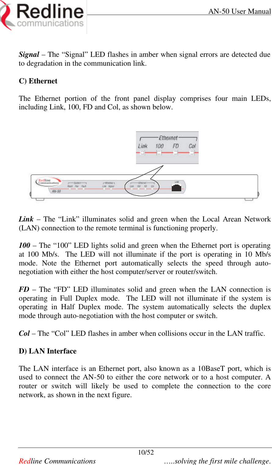
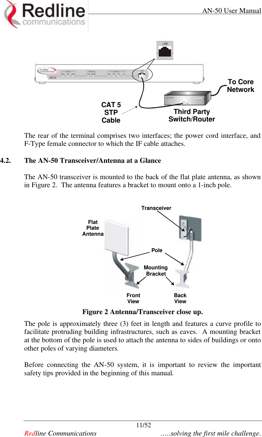
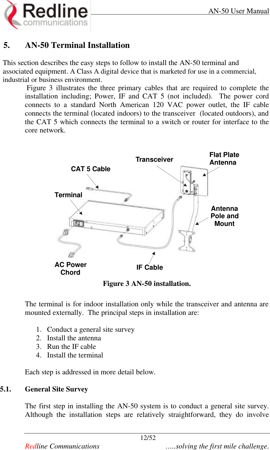
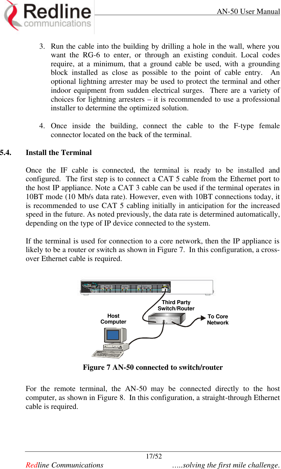
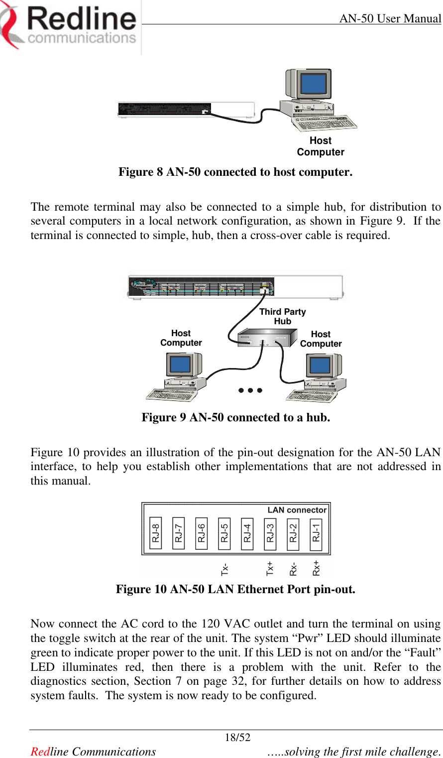
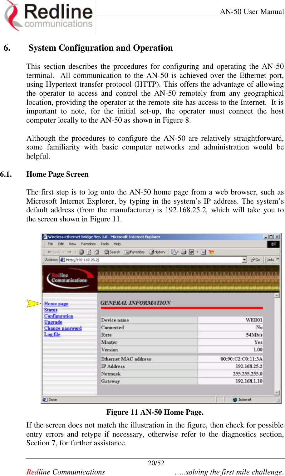
installation manual
users manual 1
Navigation menu
Upload a User Manual
Namespaces
Wiki Guide
HTML
PDF
Info
Views
User Manual
Discussion / Help
Navigation