Redline Communications AN50 Access Node User Manual AN 50 v19
Redline Communications Inc. Access Node AN 50 v19
UserManual.wiki
>
Redline Communications
>
AN50 User Manual
>
users manual 2
Contents
1.
users manual 1
2.
users manual 2
3.
installation manual
users manual 2
Navigation menu
Upload a User Manual
Namespaces
Wiki Guide
HTML
PDF
Info
Views
User Manual
Discussion / Help
Navigation
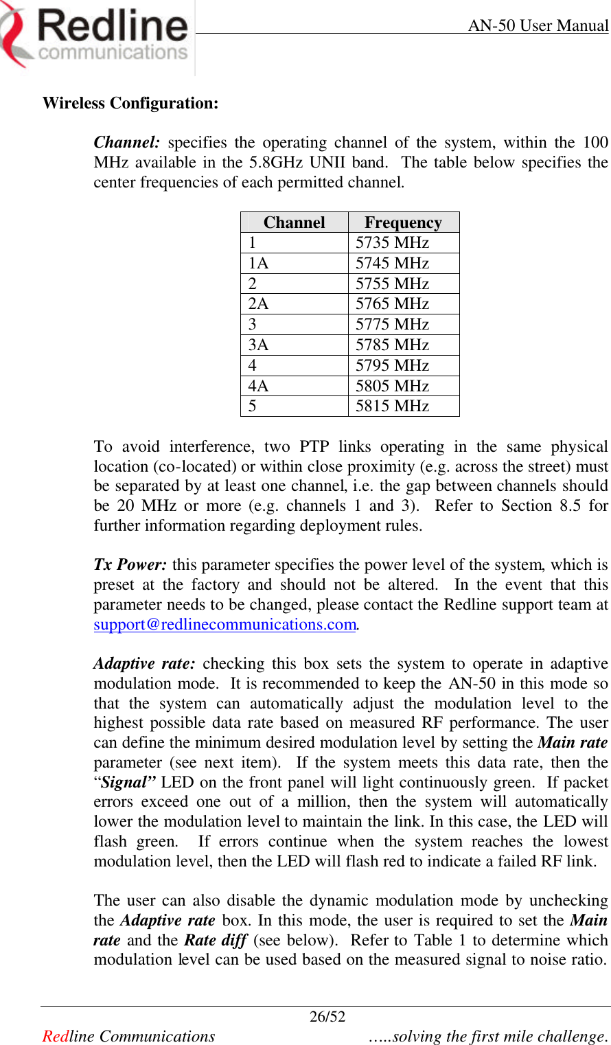
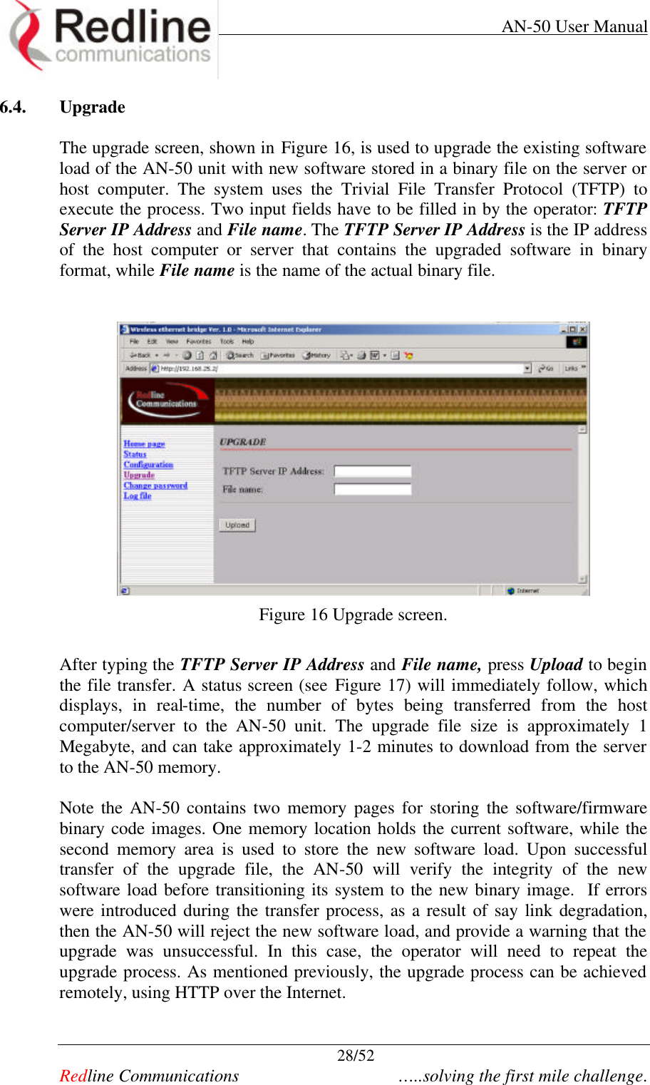
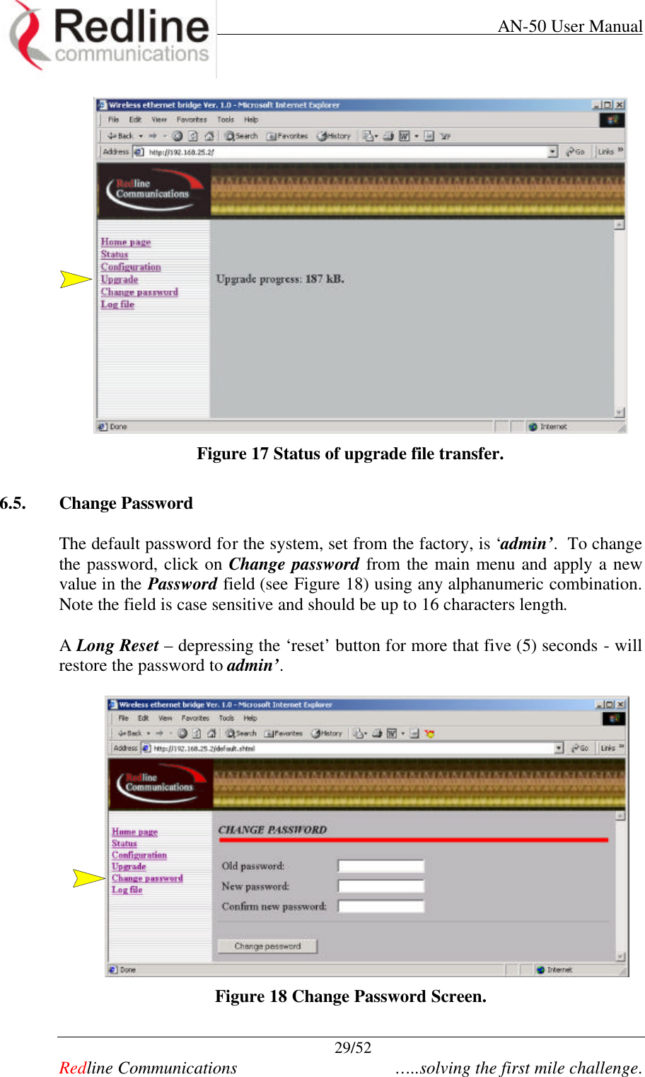
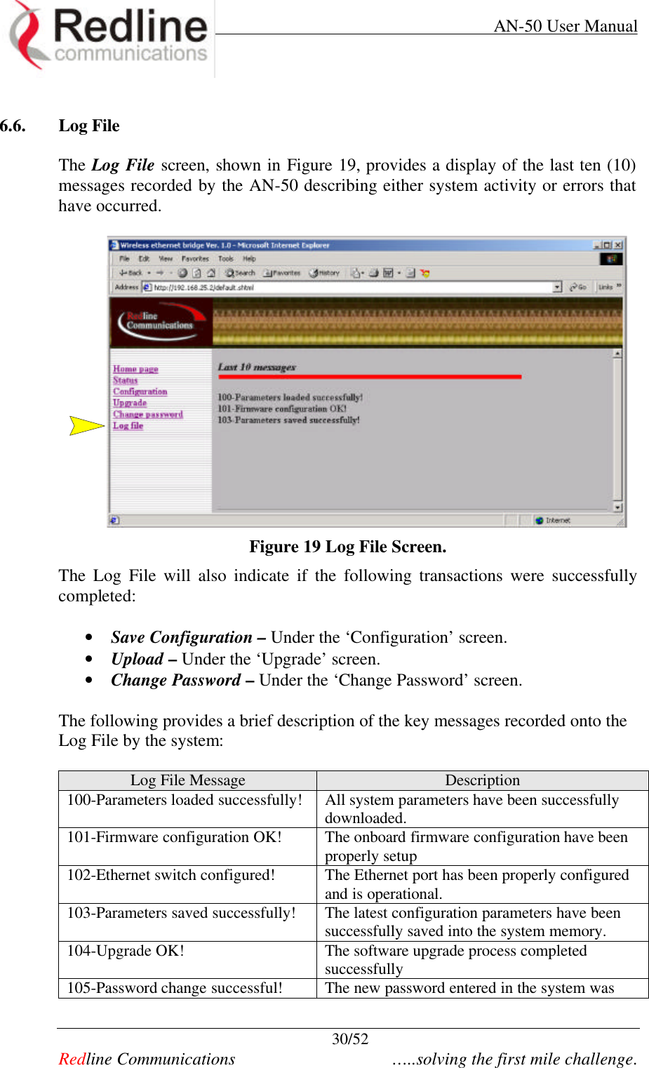
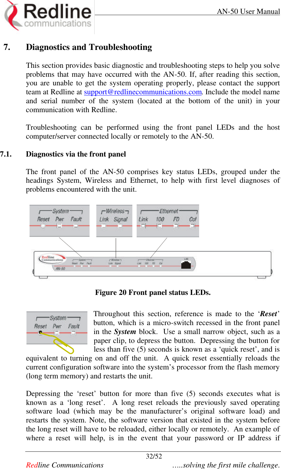
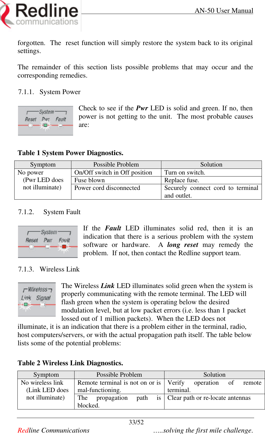
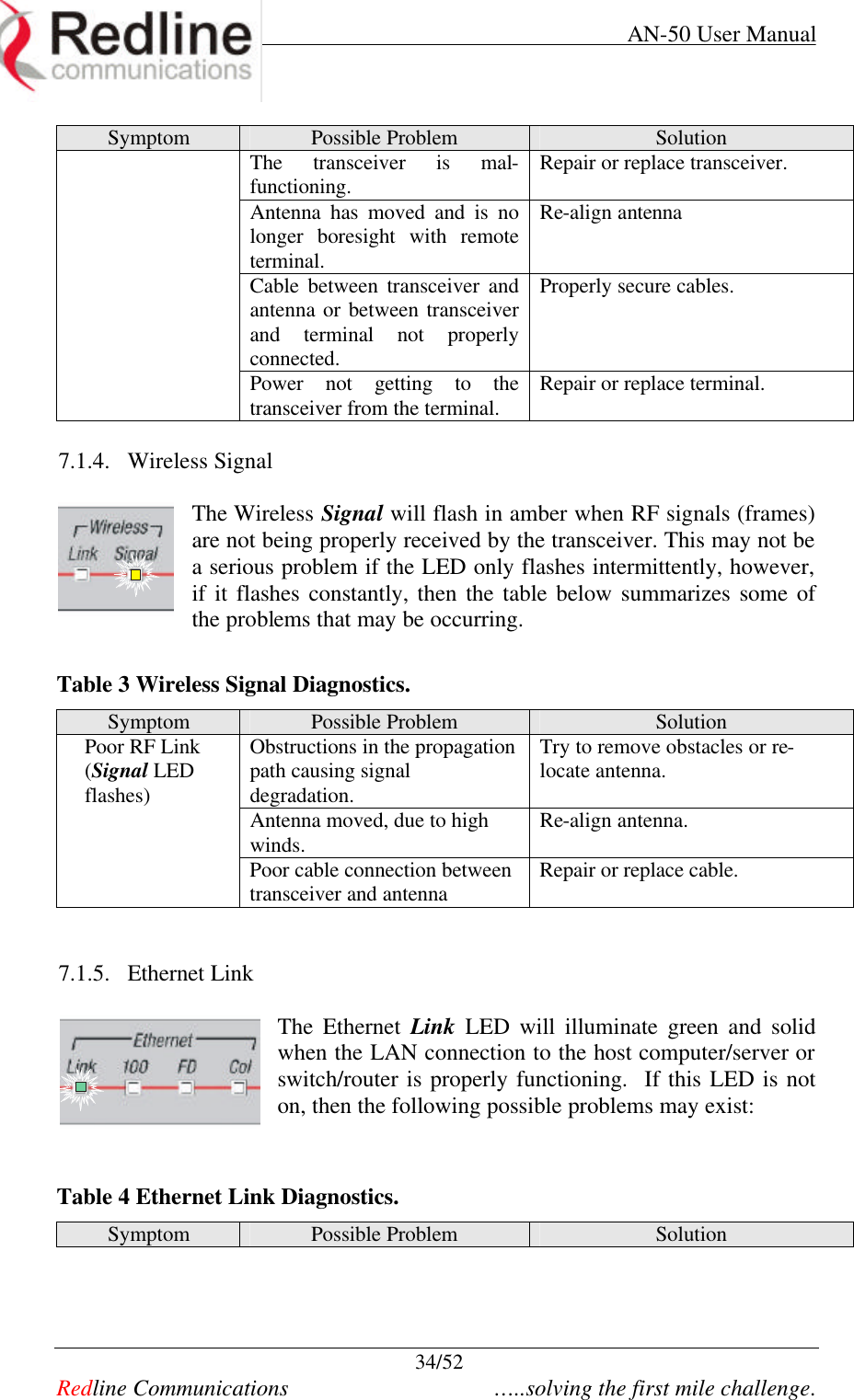
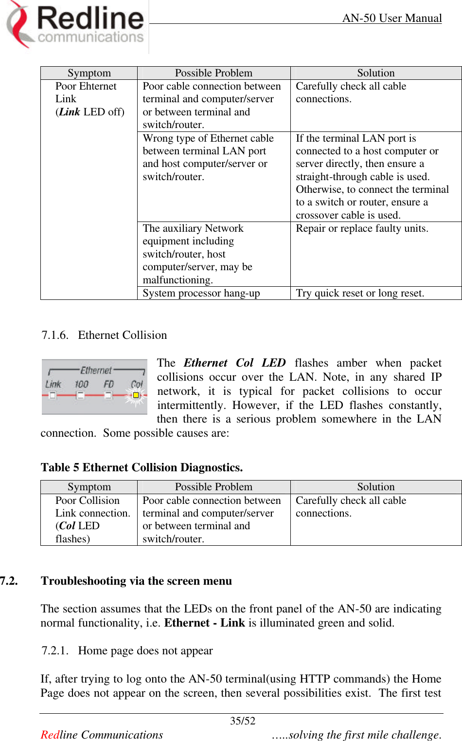
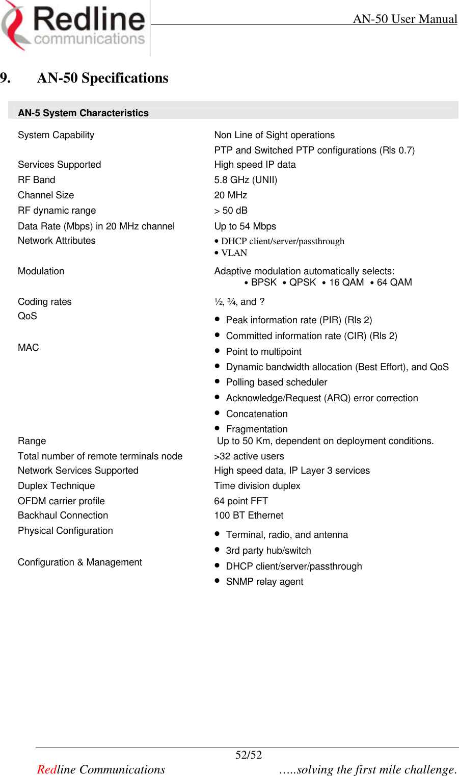
![AN-50 User Manual 27/52 Redline Communications …..solving the first mile challenge. It is recommended not to operate the system in manual mode, as this mode is intended primarily for field support. Note the “Signal” LED will light solid green when the packet error rate is less than 1 out of a million. When the errors exceed this limit, the LED will not illuminate, indicating the RF link has failed. Main rate [Mb/s]: Defines the desired net data rate for the link. Rate dif.: applies when the Adaptive rate is disabled. Rate dif specifies how many levels the system must drop in modulation before beginning re-transmission to address packet errors. The Rate diff value can be set from 1-7, with 2 being the typical value. Master: Sets the AN-50 system to serve as the Master system, while the other AN-50 assumes a slave role. Version: Specifies the current version of the system software. Note, software can be remotely downloaded into the AN-50. The system comprises sufficient memory to hold two independent software loads – the operator can specify which load to download into the system. Peak Transmitted Power per channel and modulation The maximum conducted power is limited by the software / firmware to limit the maximum power for each channel. According to the rating showed in the following table based on direct measurements the maximum power for each channel isn’t user modifiable: PEAK TRANSMIT POWER (Measured a Peak Power Meter) (dBm) Transmitted Channel Frequency (MHz) 64QAM (54 Mb/s) 16QAM (36 Mb/s) QPSK (18 Mb/s) BPSK (9 Mb/s) 1 5.735 -7.4 -7.4 -7.4 -7.4 1A 5.745 16.6 16.6 16.6 16.6 2 5.755 17.3 17.3 17.3 17.3 2A 5.765 20.0 20.0 20.0 20.0 3 5.775 20.5 20.5 20.5 20.5 3A 5.785 20.0 20.0 20.0 20.0 4 5.795 17.3 17.3 17.3 17.3 4A 5.805 16.6 16.6 16.6 16.6 5 5.815 -7.4 -7.4 -7.4 -7.4](https://usermanual.wiki/Redline-Communications/AN50.users-manual-2/User-Guide-254770-Page-2.png)