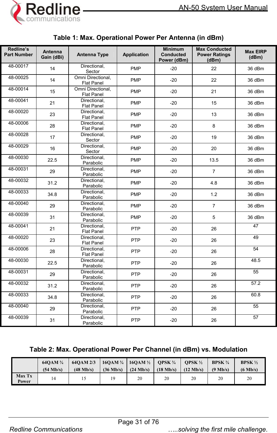
Redline Communications AN50S AN50S WIRELESS ETHERNET BRIDGE User Manual Getting Started
Redline Communications Inc. AN50S WIRELESS ETHERNET BRIDGE Getting Started
UserManual.wiki
>
Redline Communications
>
AN50S User Manual
>
USERS MANUAL
Contents
1.
users manual
2.
FCC info to users
3.
USERS MANUAL
USERS MANUAL
Navigation menu
Upload a User Manual
Namespaces
Wiki Guide
HTML
PDF
Info
Views
User Manual
Discussion / Help
Navigation
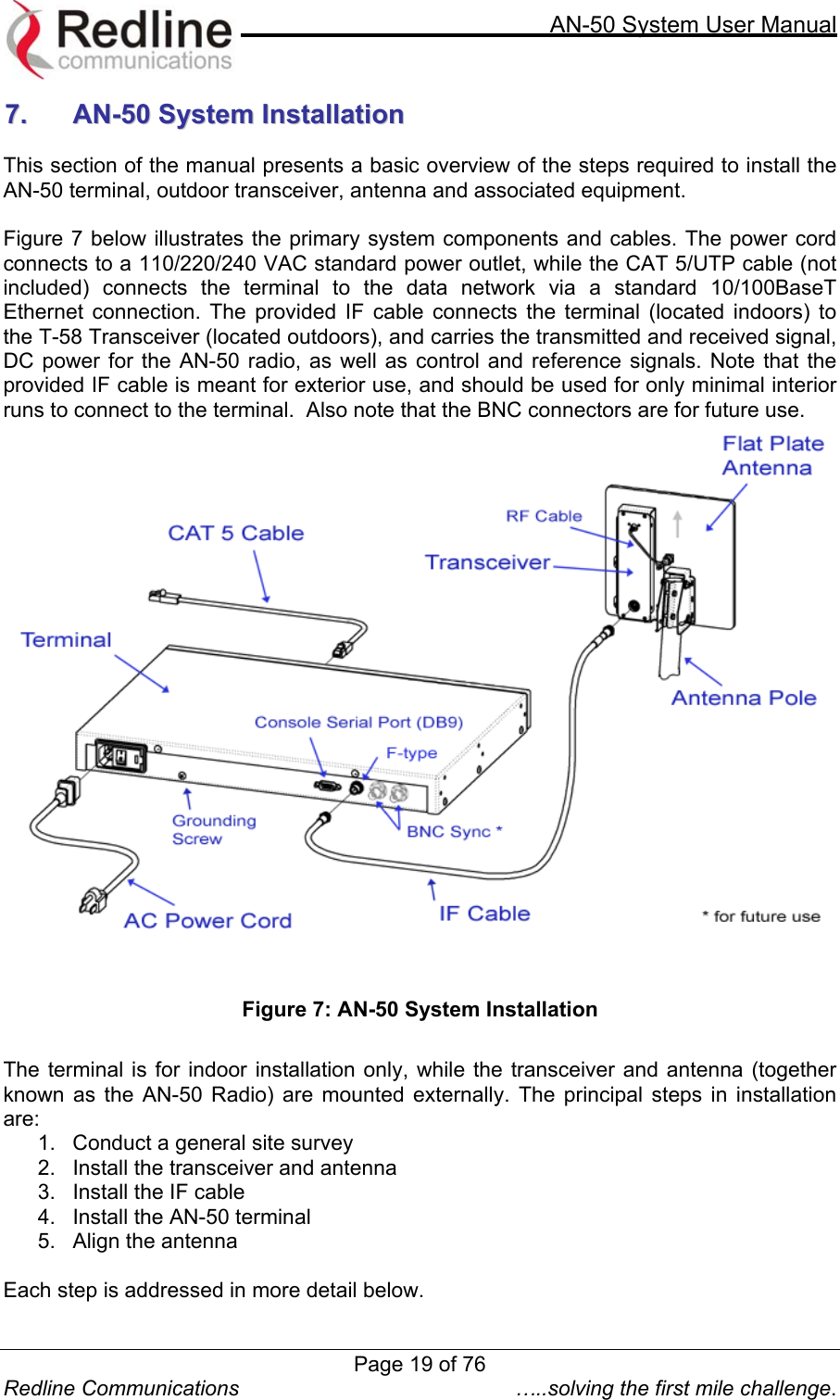
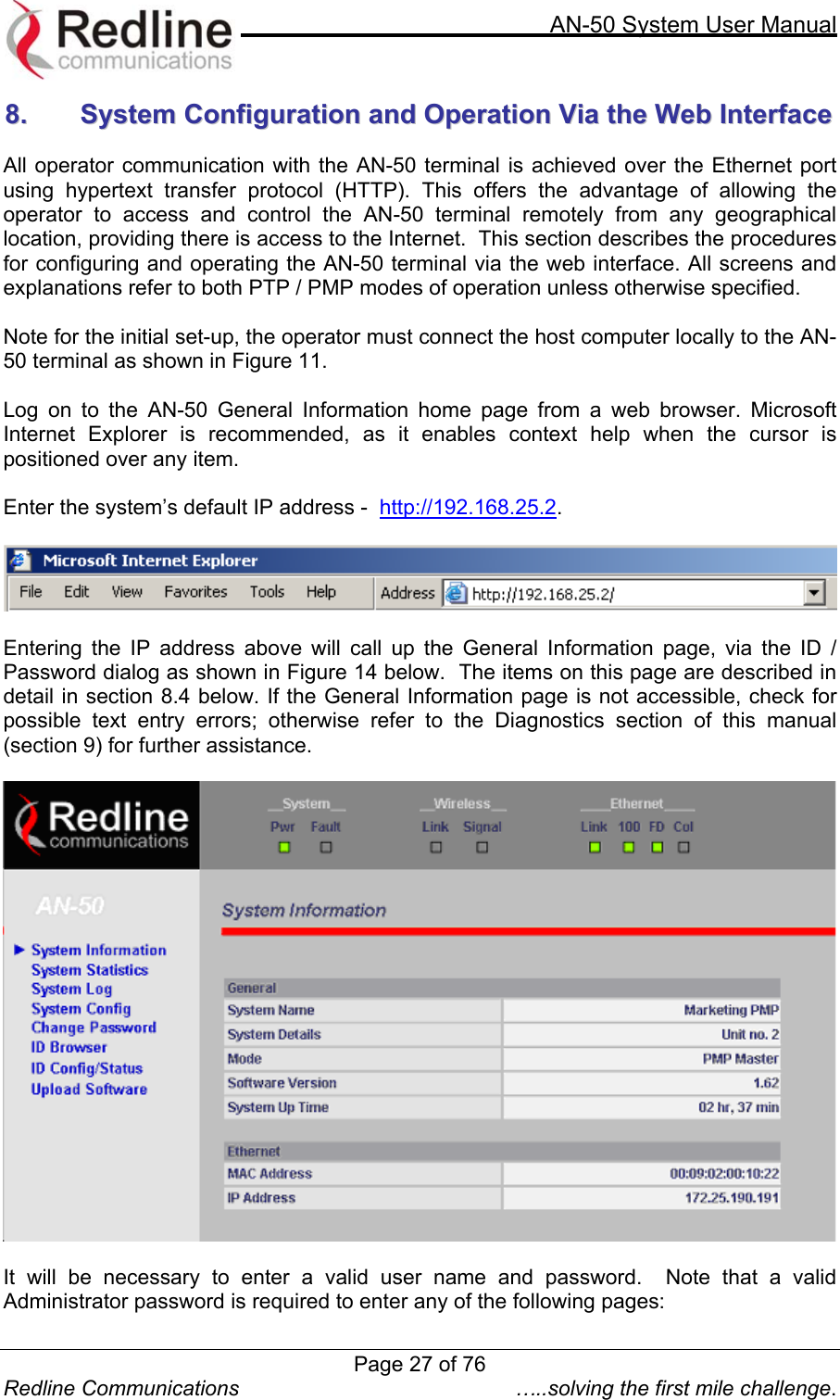
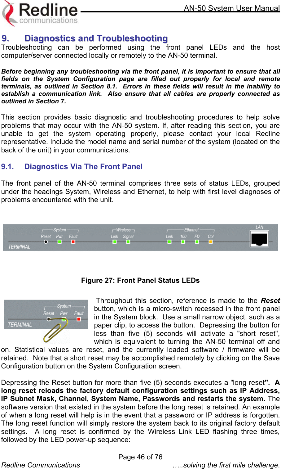
![AN-50 System User Manual AN-50 System User Manual [PTP/PMP] Manual 70-00001-01R00 Release 2.01](https://usermanual.wiki/Redline-Communications/AN50S.USERS-MANUAL/User-Guide-377145-Page-1.png)
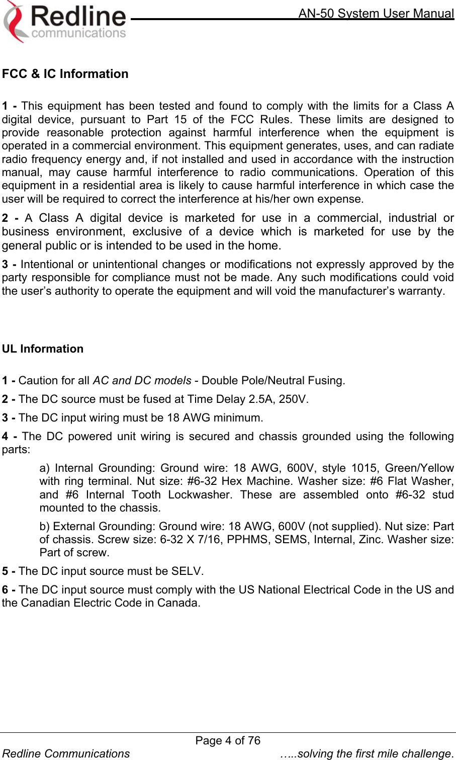
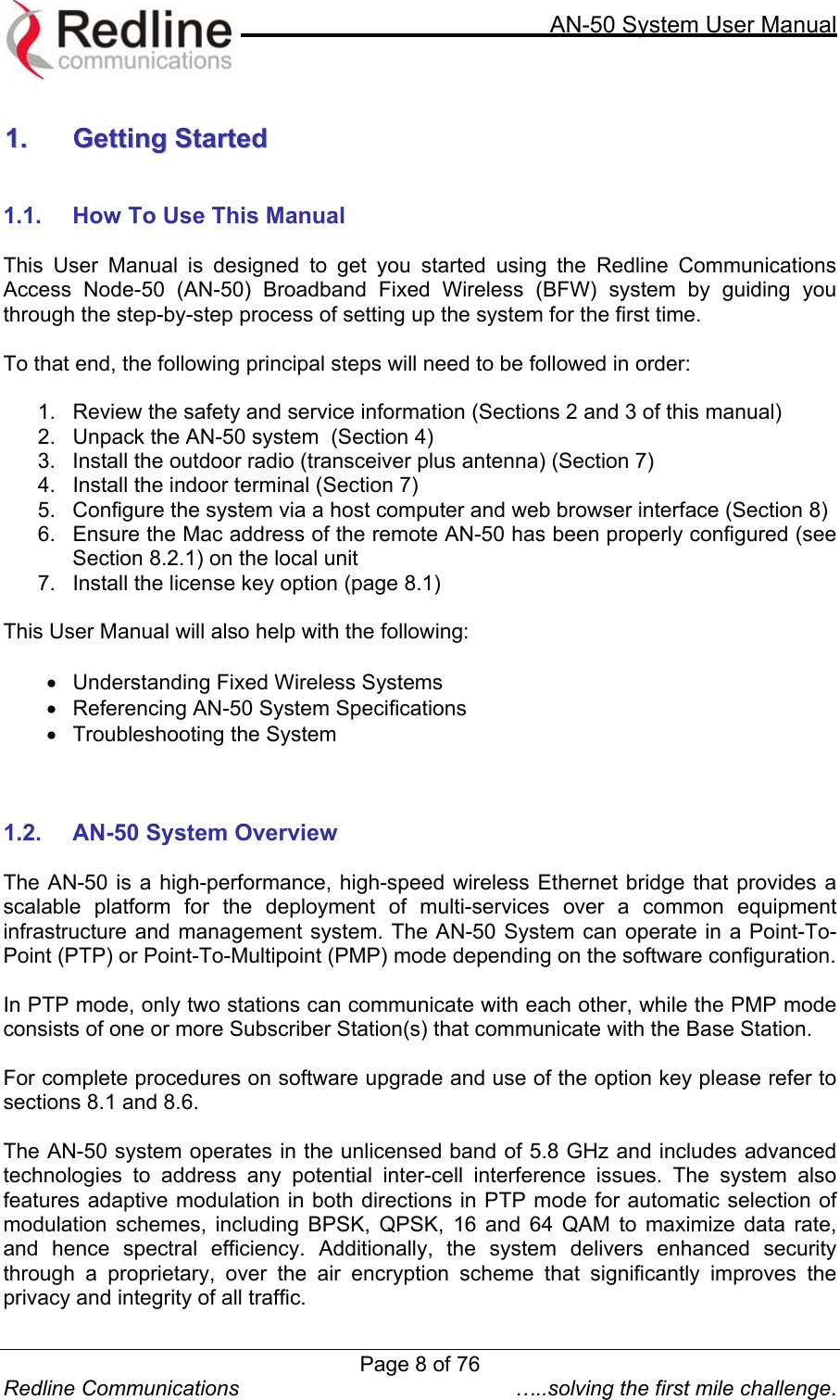
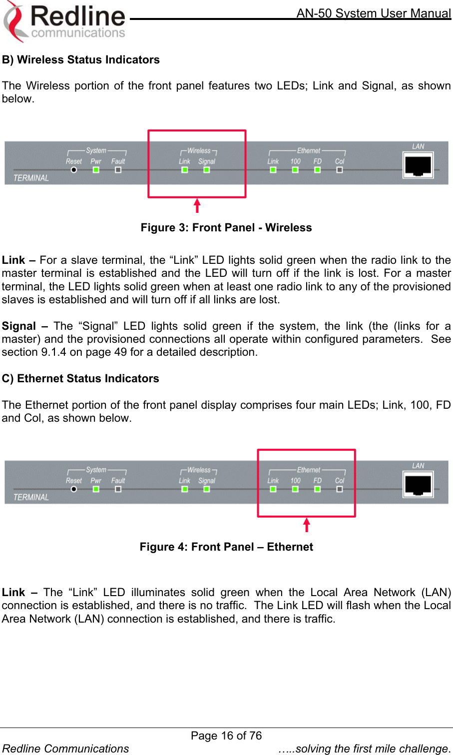
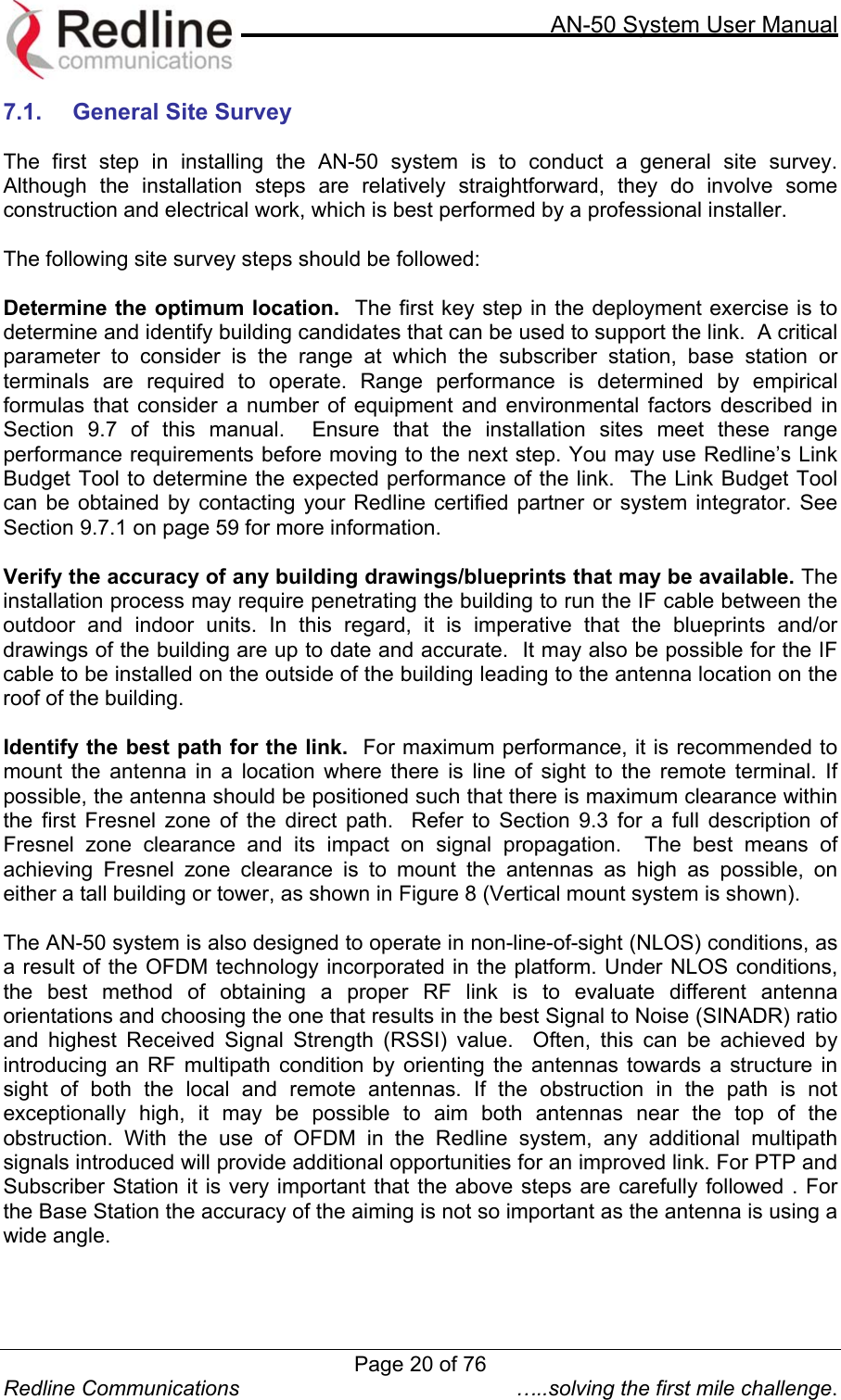
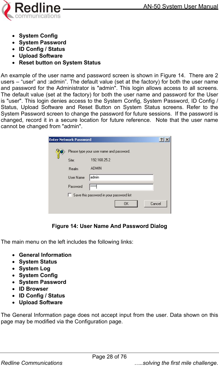
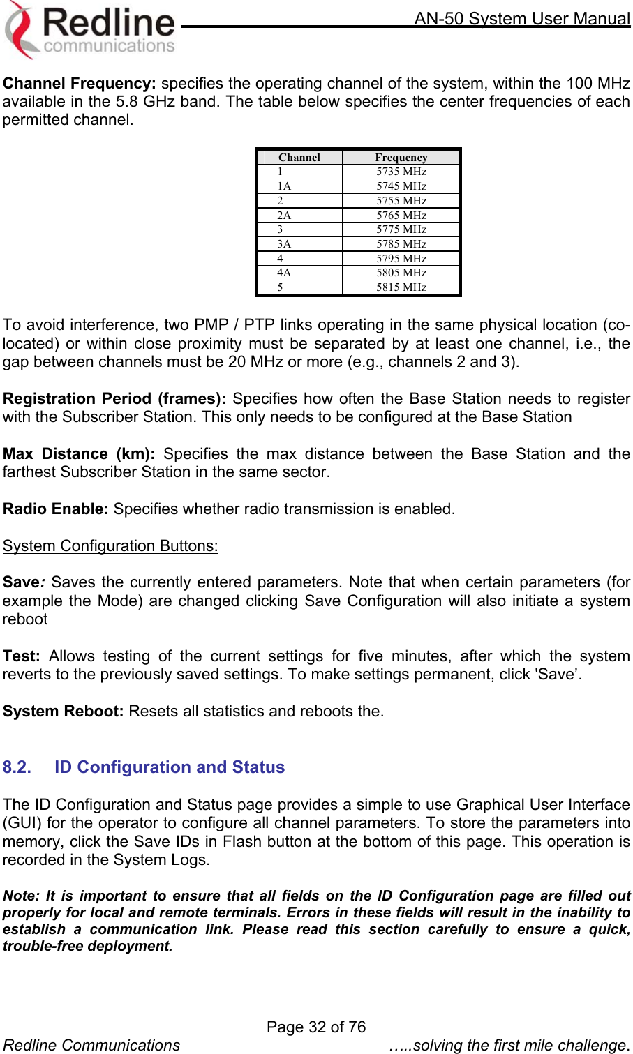
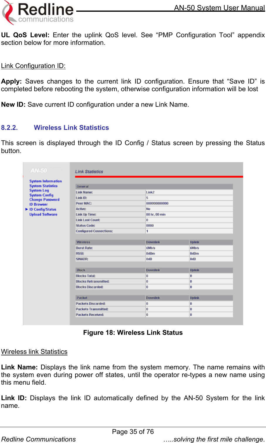
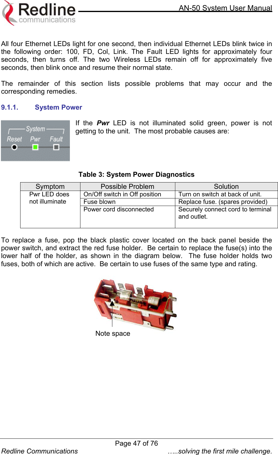
![AN-50 System User Manual Redline Communications …..solving the first mile challenge. Peer MAC: Shows the MAC address of the subscriber station Active: "Yes" indicates the RF link with the remote terminal is established. "No" indicates there is no RF link to the remote terminal. This indicator is correlated to the Wireless Link LED of the slave AN-50. Link up time: Specifies the time since the unit was started. Link Lost Count: Specifies how many times the link was lost since system was started. Status Code: A code shown as a hex number indicating the condition of the RF components within the AN-50 terminal and T-58 Transceiver. Configured Connections: Shows the total number of connections configured for this link. For the current AN-50 revision the system will always display one (1) connection. Link Status Downlink / Uplink: Burst Rate [Mb/s]: Indicates for this wireless link the current Tx burst rate used by the master (downlink) and by the slave (uplink) .. RSSI [dBm]: Indicates the average received signal strength (RSSI) at slave (downlink) and master (uplink). SINADR [dB]: Indicates the average signal to interference noise and distortion ratio (SINADR) at slave (downlink) and master (uplink). The ratio is based on the digital information provided from the output of the A/D converter and includes the effects of the AGC. Link Statistics Downlink / Uplink: Blocks Total: Shows the total blocks transmitted from master to slave (downlink) and from slave to master (uplink). Note that, in order to utilize efficiently the wireless bandwidth and to allow tight QoS control, the system fragments and concatenates Ethernet packets in blocks, where blocks are then transmitted over the air. Blocks Retransmitted: Shows the total blocks retransmitted. Blocks Discarded: Shows the total blocks lost Packets Discarded: Indicates the total number of packets discarded due a full buffer full Packets Transmitted: Indicates the total number of packets transmitted. Packets Received: Indicates the total number of packets received. Page 36 of 76](https://usermanual.wiki/Redline-Communications/AN50S.USERS-MANUAL/User-Guide-377145-Page-36.png)
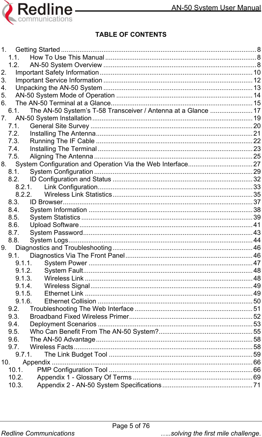
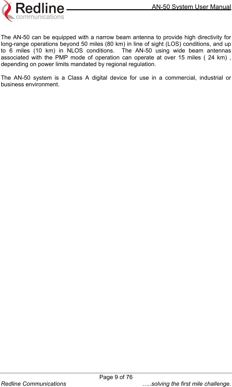
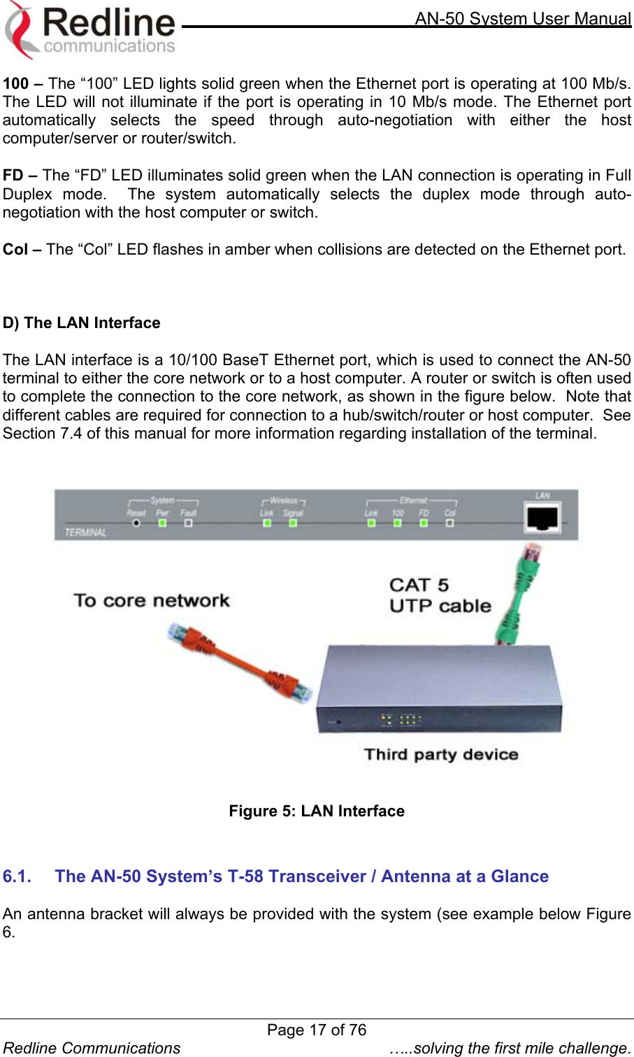
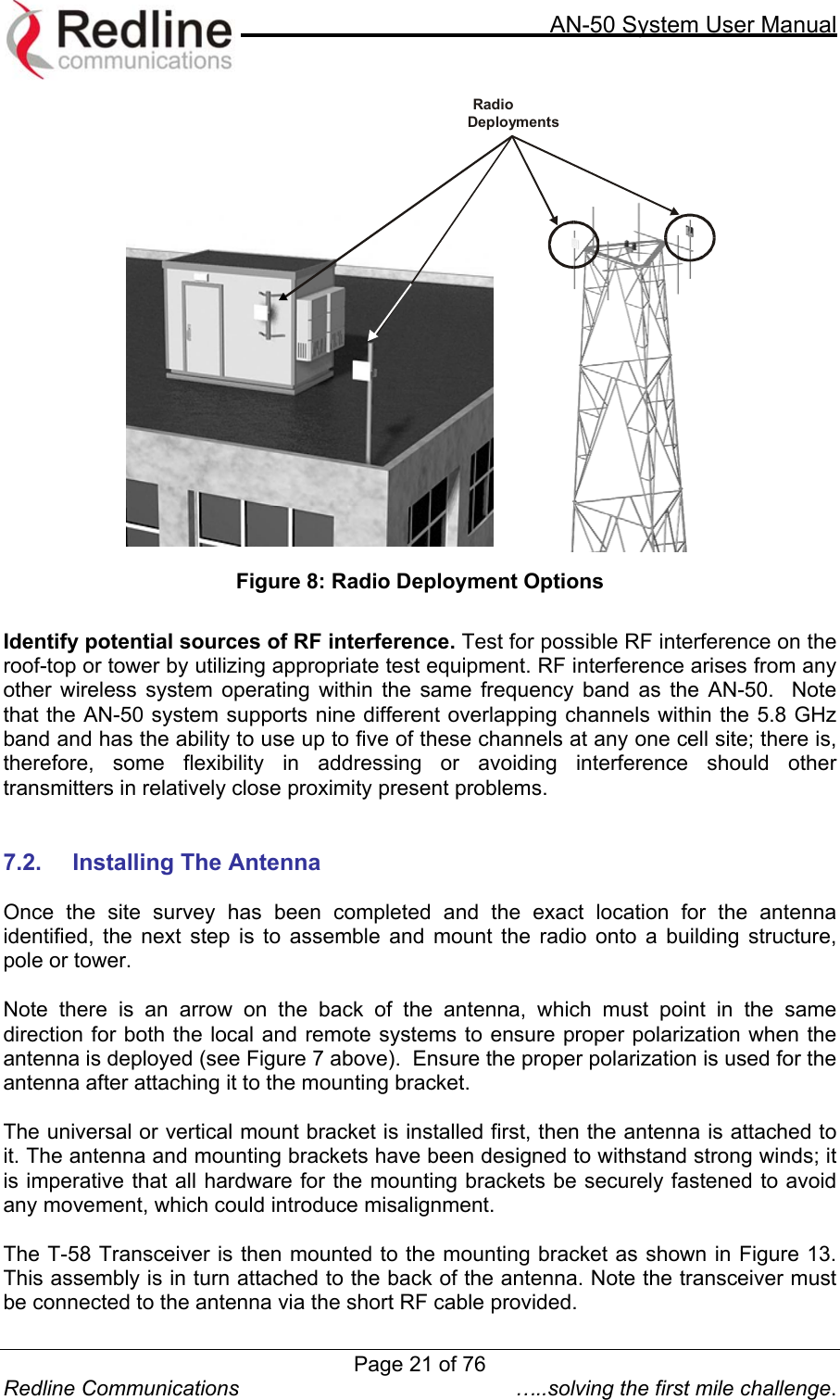
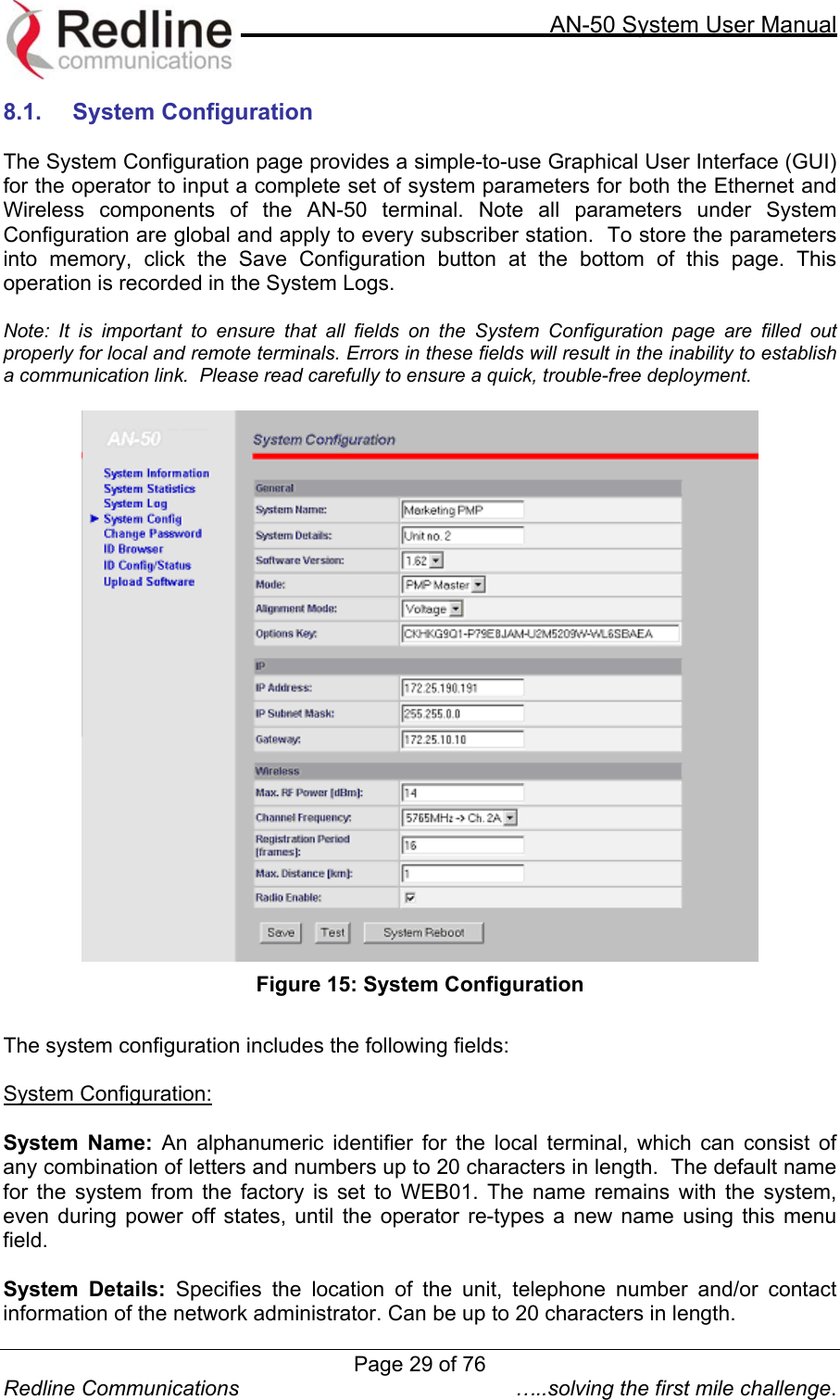
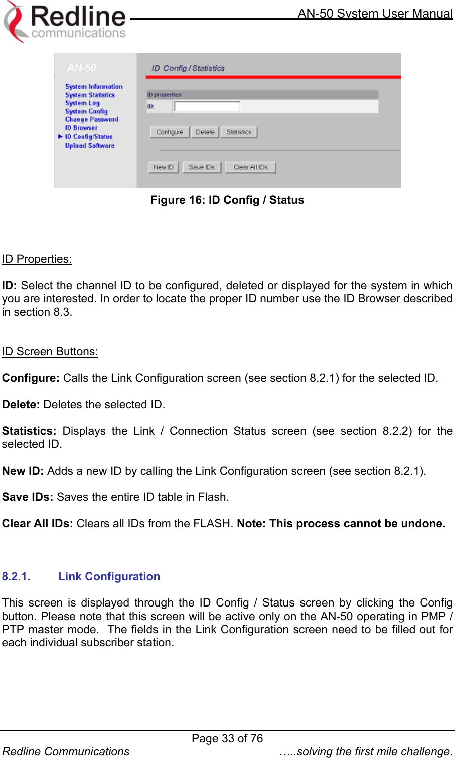
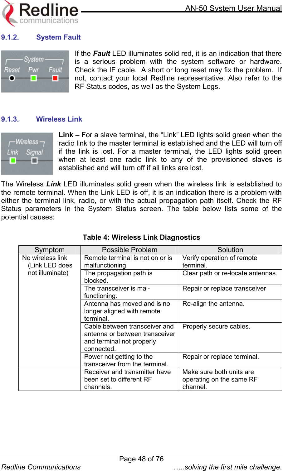
![AN-50 System User Manual Redline Communications …..solving the first mile challenge. 8.4. System Information Figure 21: AN-50 General Information Located at the top of this page is a graphic interface providing a real-time synoptic view of the AN-50 terminal front panel (refreshed every 30 sec.), plus a summary of general information related to the configuration and status of the local unit. The following is a brief description of each field on the General Information page: General: System Name: Identifies the local terminal. The factory default name for the system is “WEB01”. System Details: Specifies the location, telephone number and/or contact information. Mode: Specifies whether the AN-50 operates in PMP / PTP master or slave. Software Version: Specifies the software version in use. System Up Time: Specifies the time [dd/hh/mm/ss] since the system started. Ethernet: Ethernet MAC Address: Specifies the Ethernet MAC address used by the local terminal. IP Address: Specifies the IP address used by the local terminal. Page 38 of 76](https://usermanual.wiki/Redline-Communications/AN50S.USERS-MANUAL/User-Guide-377145-Page-38.png)
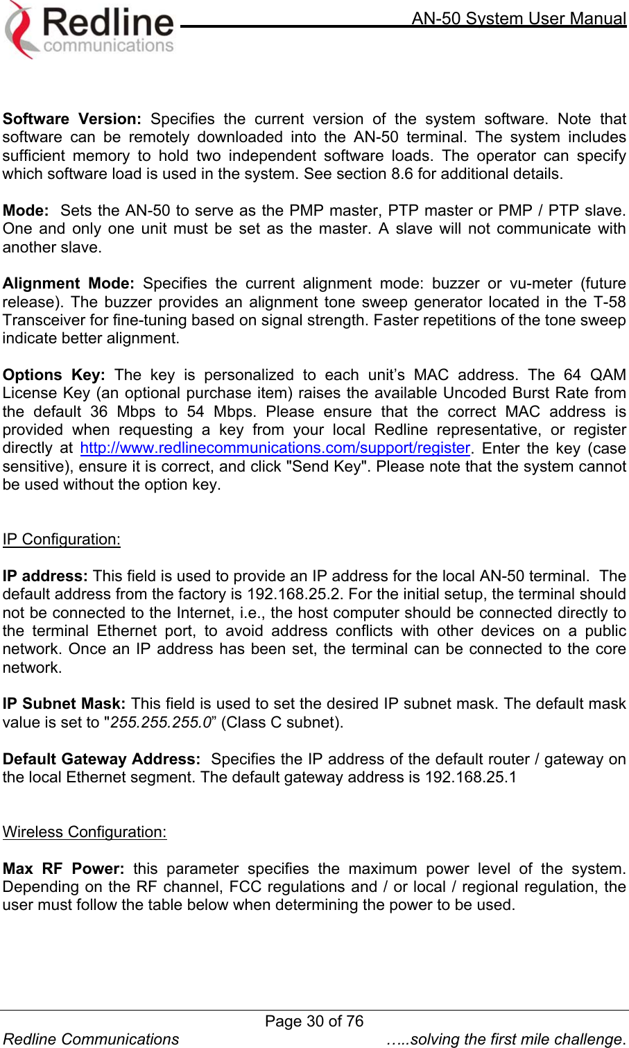
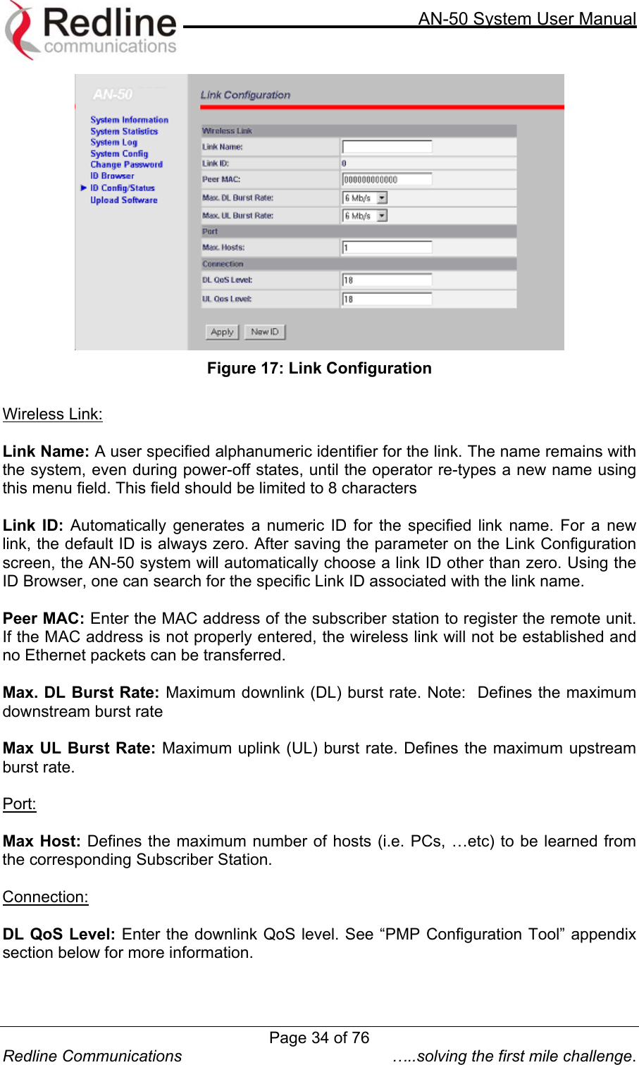
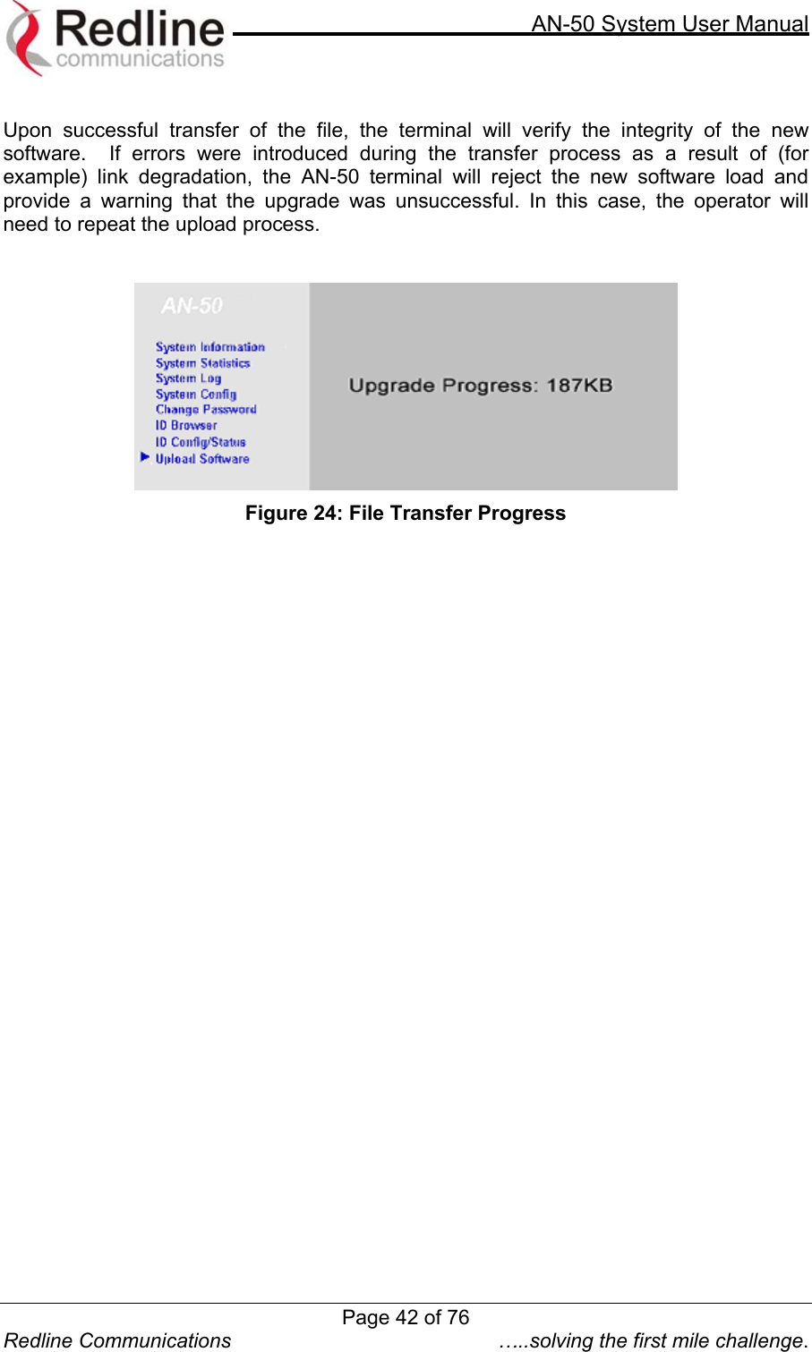
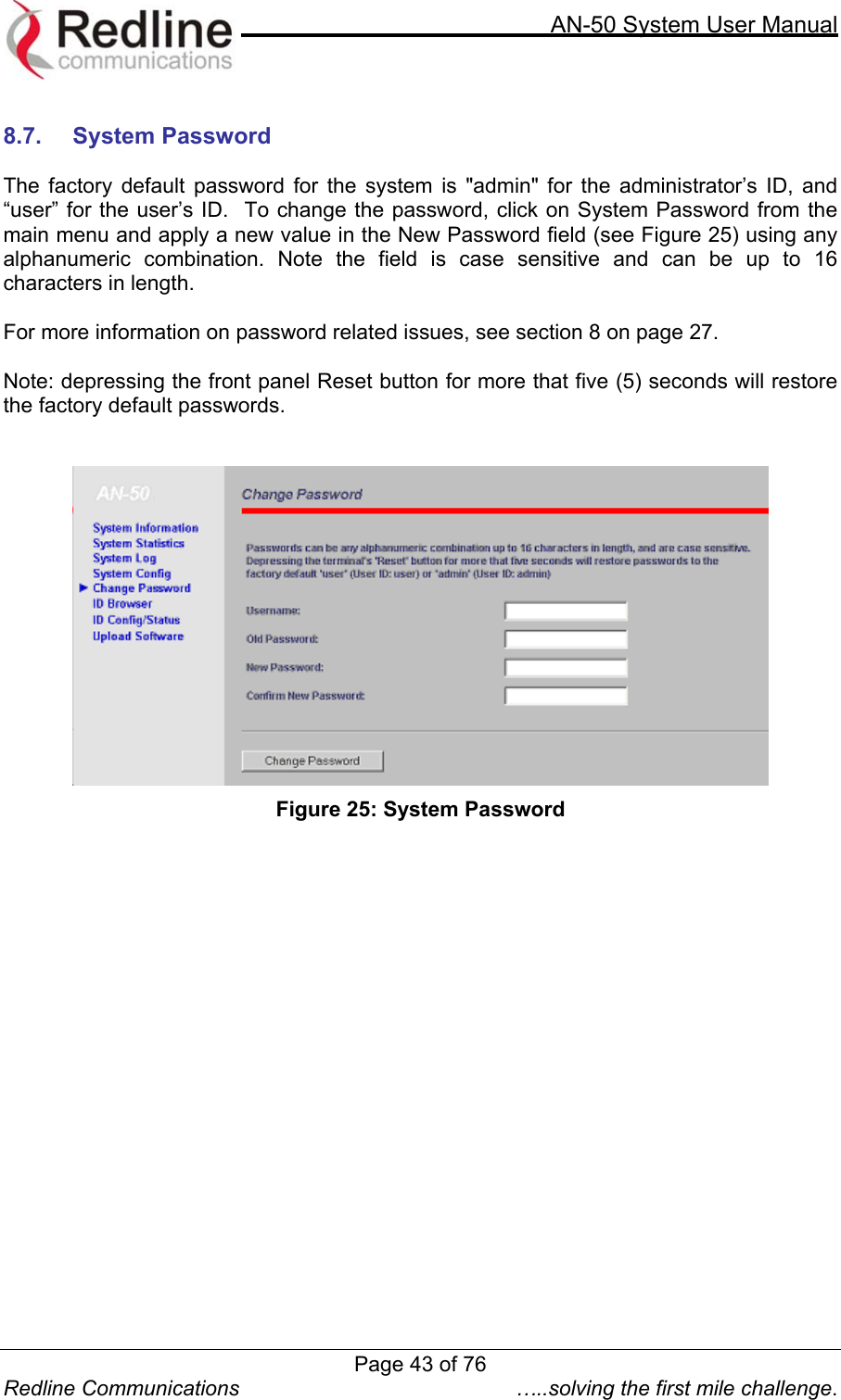
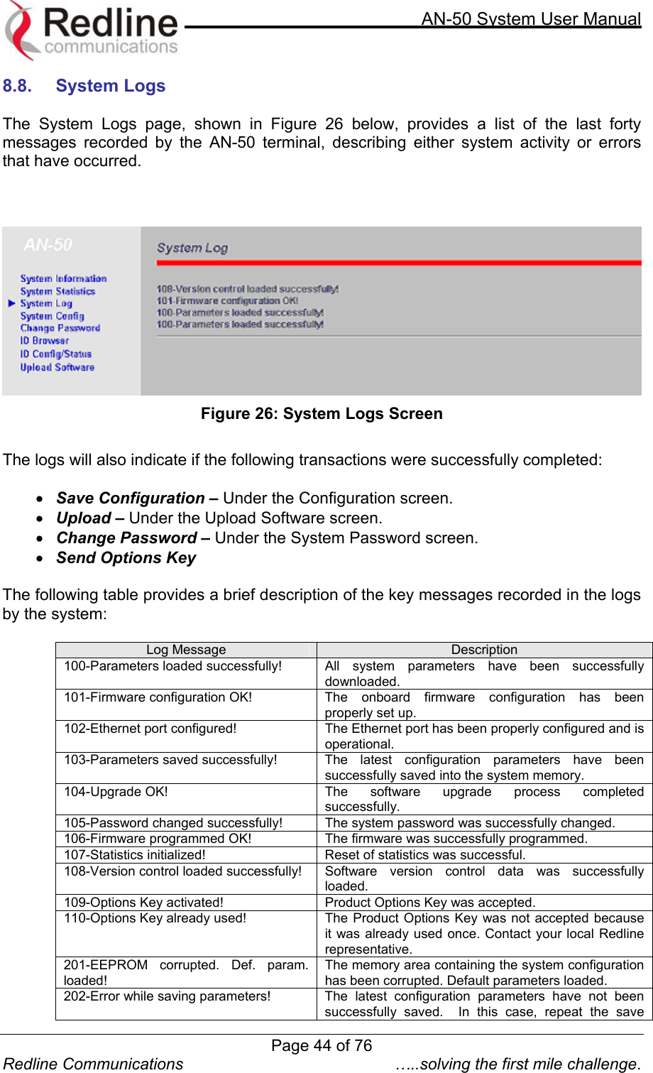
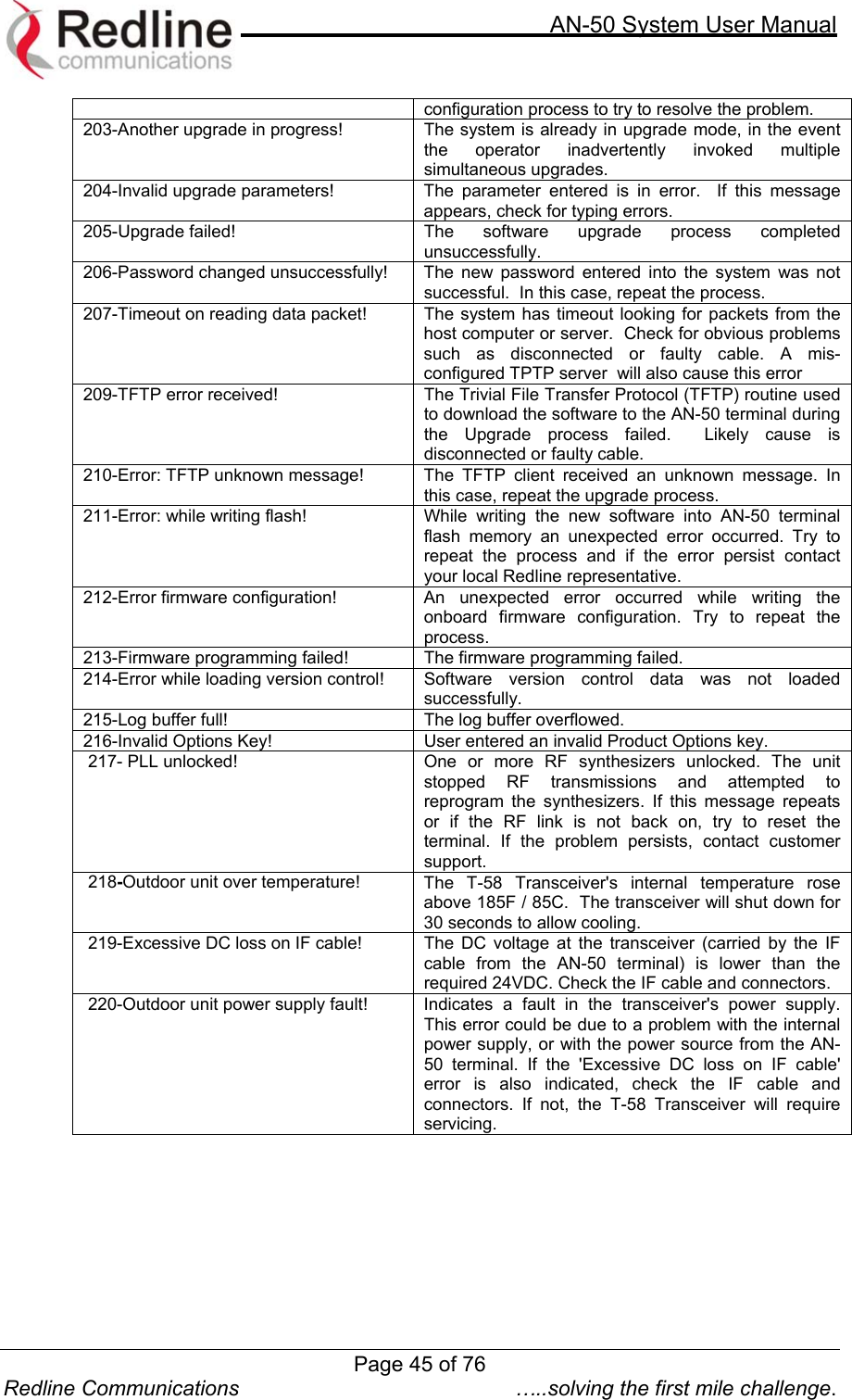
![AN-50 System User Manual Redline Communications …..solving the first mile challenge. 8.6. Upload Software To move from a PTP to PMP configuration, one end must be designated as the new Base Station (BS) site, the software must be upgraded, and the antenna must be changed from the typical narrow beam PTP antenna to a 60 or 90 degree sector antenna. Redline offers the necessary upgrade parts in order to accomplish this. It should be noted that when migrating a PTP system to PMP, the designated Subscriber Station (SS) side will see an overall reduction in signal strength due to the BS antenna’s lower gain. The installer must take this into consideration before upgrading any installation. Failure to do so could result in performance degradation in terms of throughput at a given range. It is recommended that customers contact their Redline Partner to calculate the expected link budget before proceeding with any upgrade. The upload screen shown below is used to upgrade the existing software load of the AN-50 terminal with new software stored in a binary file on the server or host computer. Note the AN-50 terminal contains two FLASH banks for storing two versions of the software/firmware. The user can select the operating version using the Configuration screen. The upload will always overwrite the non-operational (unselected) version; therefore it is important to select the desired operating version before beginning the upgrade process. The upgrade process is achieved remotely, using the Trivial File Transfer Protocol (TFTP) over the Internet. The operator must fill in two input fields: TFTP Server IP Address and File Name. The TFTP Server IP Address is the IP address of the host computer or server that contains the upgrade software in binary format, while File Name is the name of the actual binary file. [Note: only the filename should be specified] Figure 23: Upload Software After typing the TFTP Server IP Address and File Name, click Upload File to begin the file transfer. A status screen (see Figure 24) will appear, displaying the number of bytes being transferred from the host computer/server to the AN-50 terminal in real time. The upgrade file size is approximately 1.8 MB, and will take approximately two to four minutes to download from the server to the AN-50 terminal memory. To activate the new version, it is necessary to go to the Configuration page and select the new Software Version. Page 41 of 76](https://usermanual.wiki/Redline-Communications/AN50S.USERS-MANUAL/User-Guide-377145-Page-41.png)
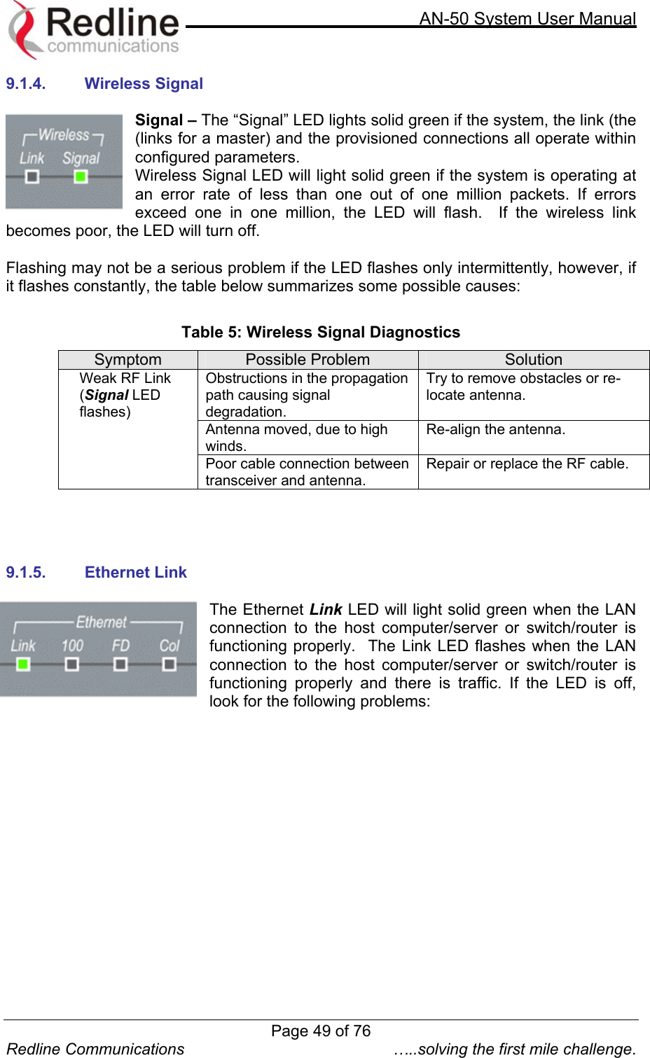
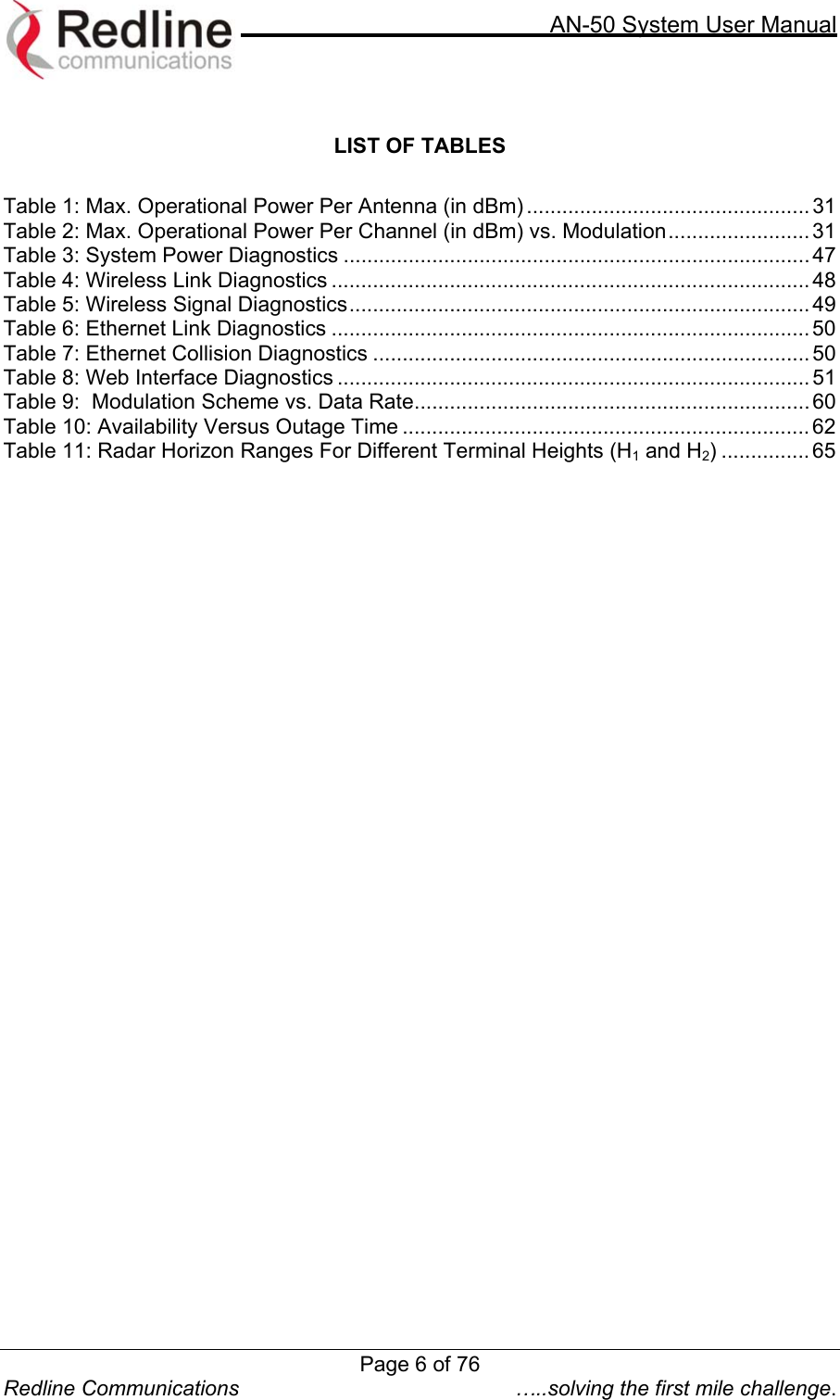
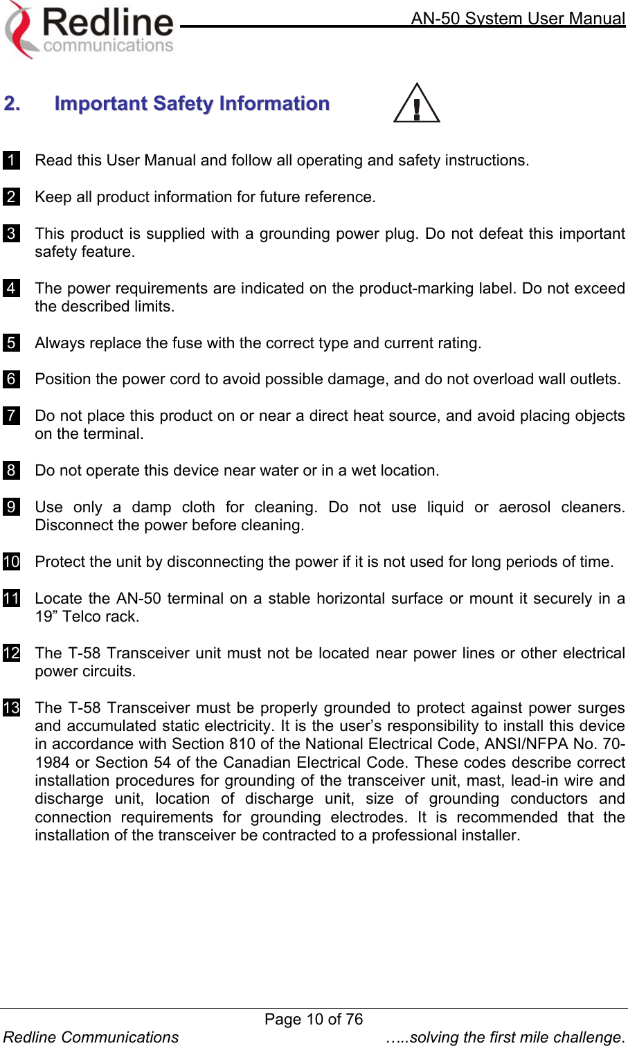
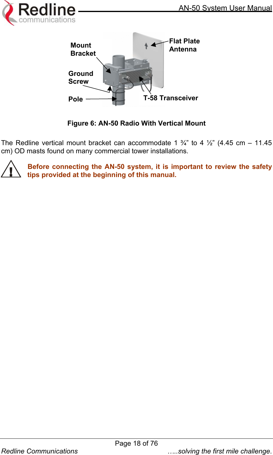
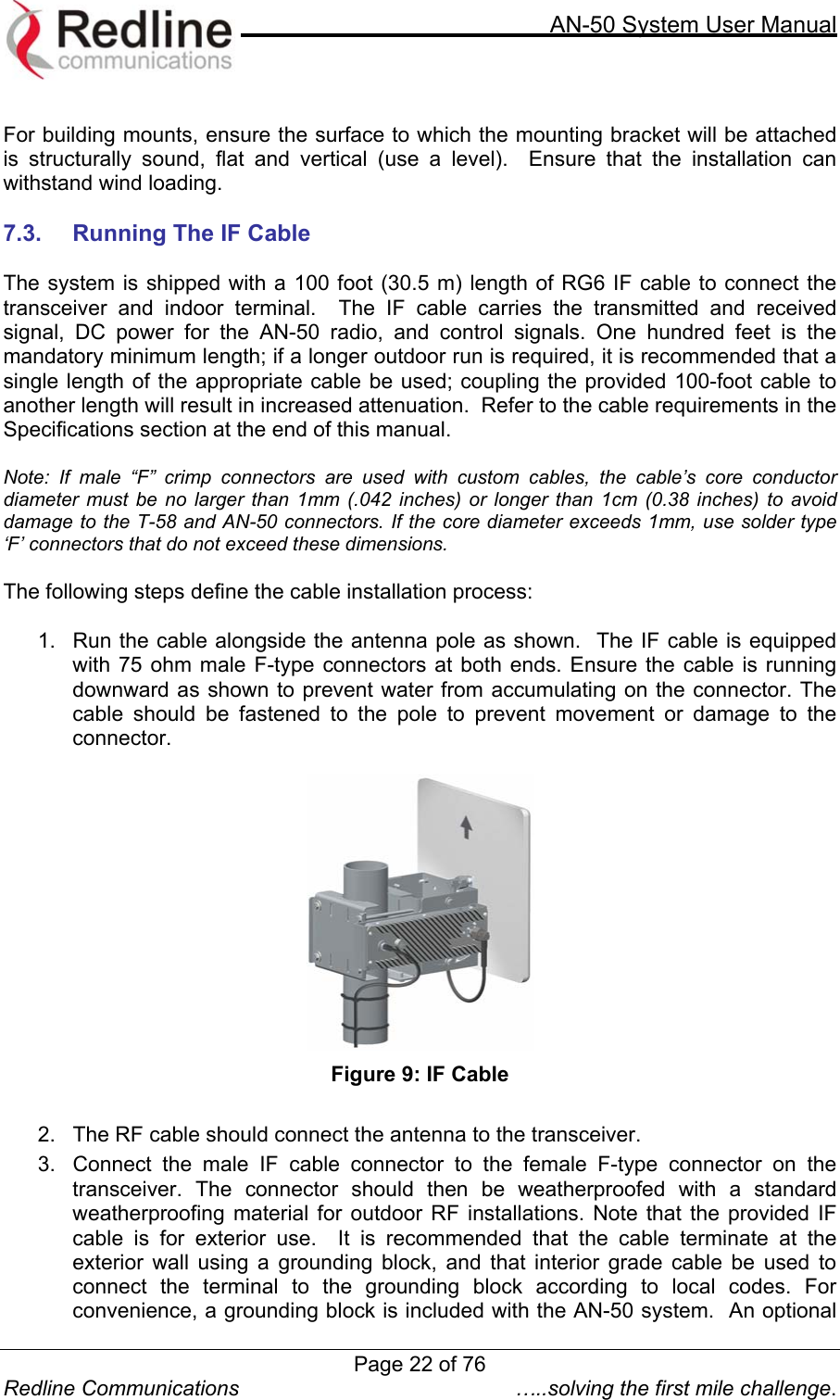
![AN-50 System User Manual Redline Communications …..solving the first mile challenge. 1100.. AAppppeennddiixx 10.1. PMP Configuration Tool The PMP Configuration tool helps calculate the desired CIR across the sector for each Subscriber Station, based on 18 programmable QoS levels. By configuring AN-50 PMP Configuration tool with the sector parameters (numbers in black) the CIR of each Subscriber Station can be adjusted as desired. Then the AN-50 needs to be configured using the green values that were calculated based on the input provided. A typical display of the configuration tool is shown below. Three different colored numbers are used as follow: 1. White – User desired performance parameters for the Subscriber Stations within the sector 2. Blue – Calculation results 3. Green – Values used for AN-50 configuration settings Usage: Fill in white boxes, verify results in blue, then config AN50 using green values. System Configuration Registration Period [frames] 50 Max Distance [km] 7 Max QoS Level 18 Max Traffic Latency [us] 10,745 Registration Cycle [ms] 266 Bandwidth Used [%] 70 Link ID Configuration Desired CIR [kbps] Burst Rate [Mbps] QoS Level Obtained CIR [kbps] Link ID DL UL DL UL Distance [km] DL UL DL UL 4 4,000 2,000 54 36 3 18 9 5,752 2,8725 2,000 2,000 54 36 5 9 9 2,872 2,8726 2,500 2,500 48 24 6 12 12 3,832 3,8327 2,500 1,500 54 36 2 12 7 3,832 2,2328 1,300 1,000 48 24 7 6 5 1,912 1,591 PMP Configuration Tool Data Input Registration Period (frames) – The registration period is the number of frames that the base station passes before sending out a broadcast to look for new subscribers. Input a Page 66 of 76](https://usermanual.wiki/Redline-Communications/AN50S.USERS-MANUAL/User-Guide-377145-Page-66.png)