Redline Communications AN50S AN50S Wireless Ethernet Bridge User Manual Getting Started
Redline Communications Inc. AN50S Wireless Ethernet Bridge Getting Started
UserManual.wiki
>
Redline Communications
>
AN50S User Manual
>
users manual
Contents
1.
users manual
2.
FCC info to users
3.
USERS MANUAL
users manual
Navigation menu
Upload a User Manual
Namespaces
Wiki Guide
HTML
PDF
Info
Views
User Manual
Discussion / Help
Navigation

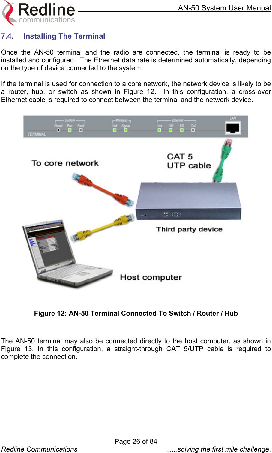
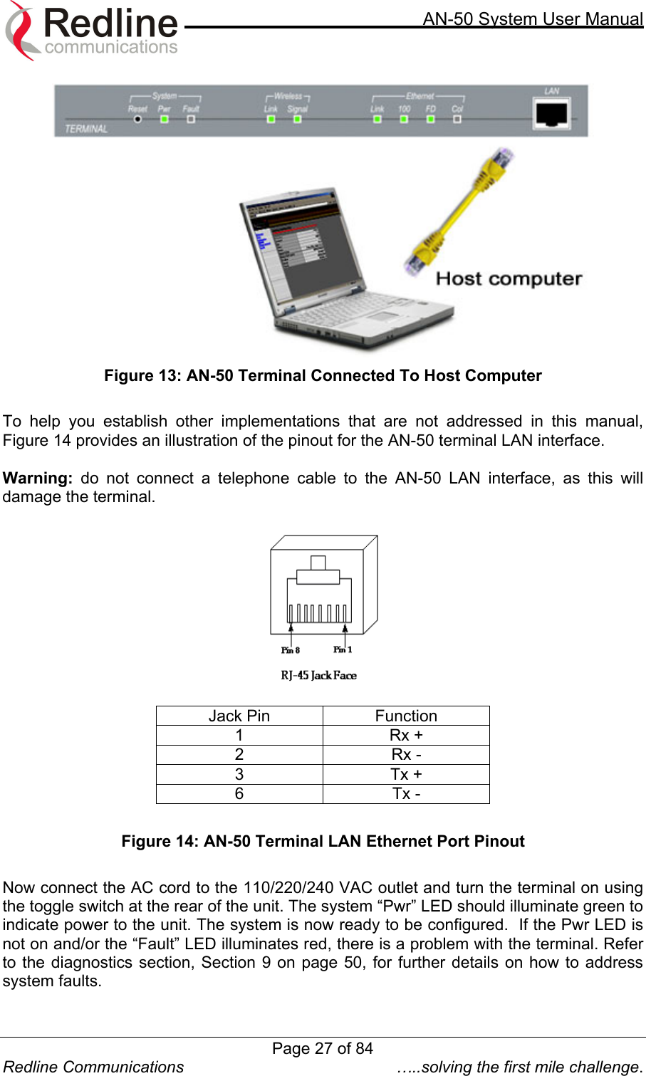
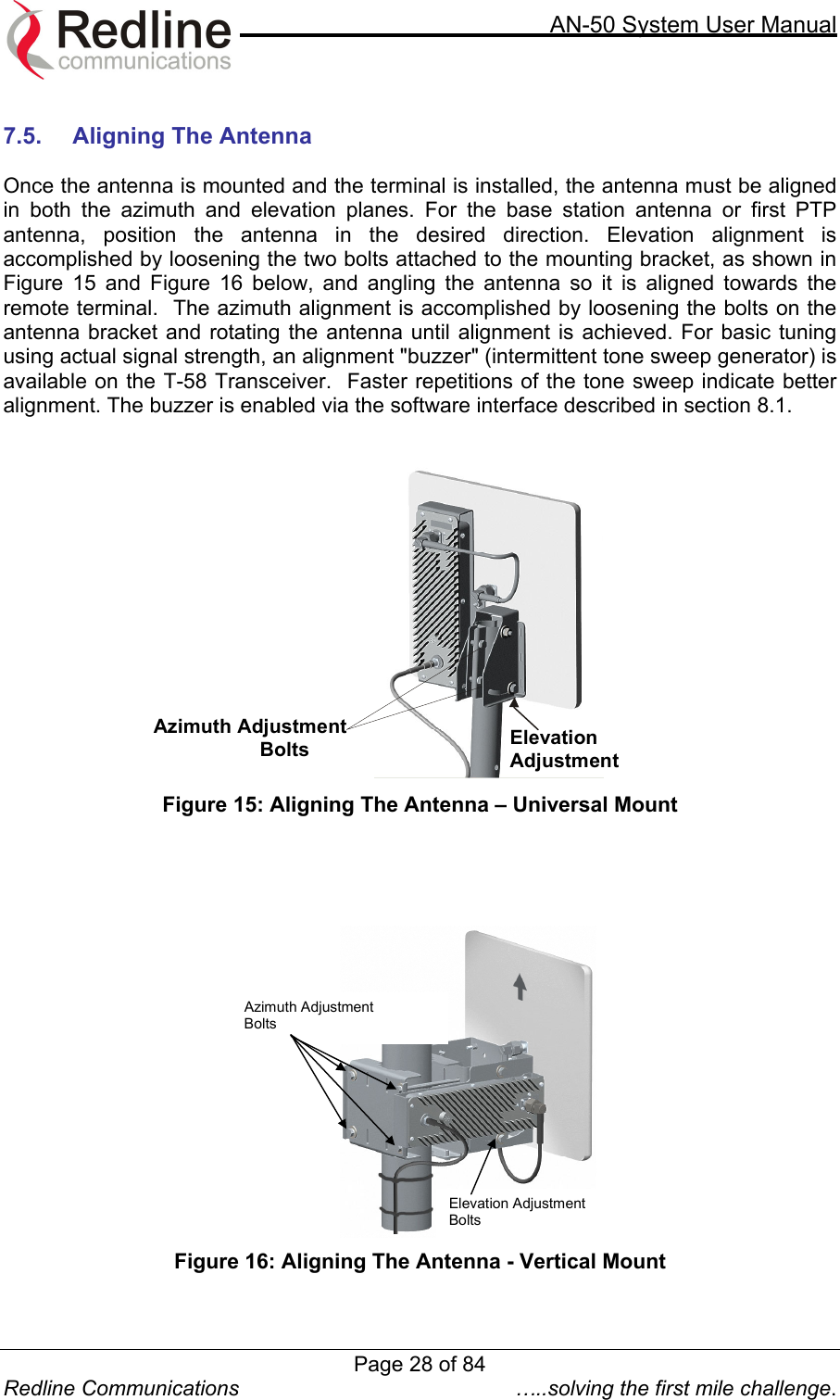
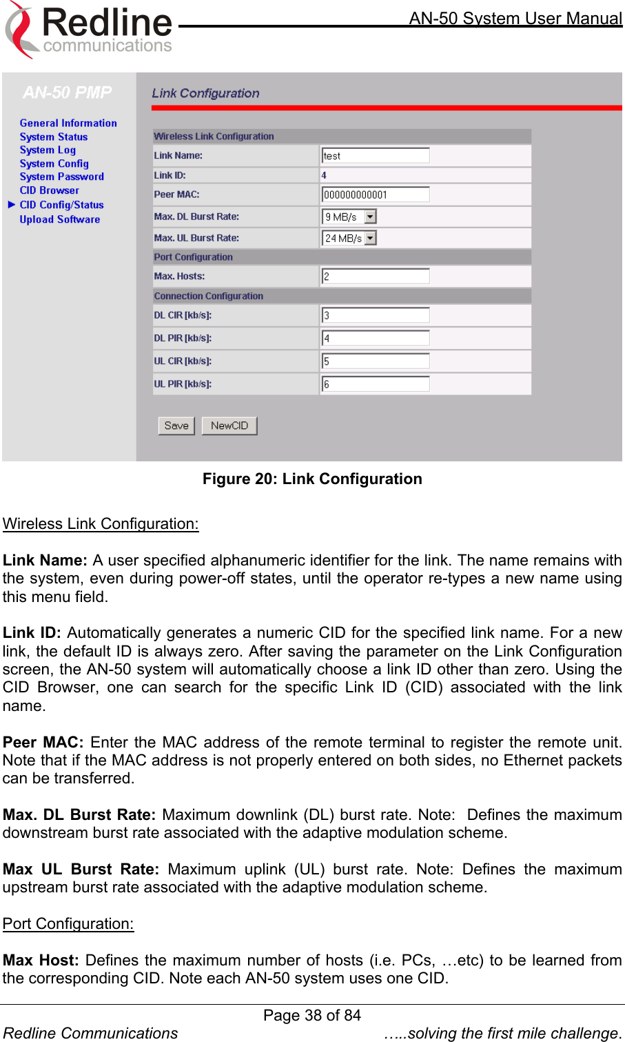
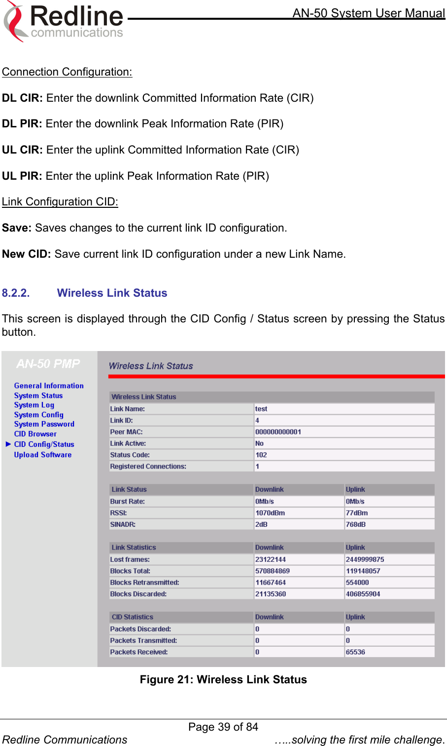
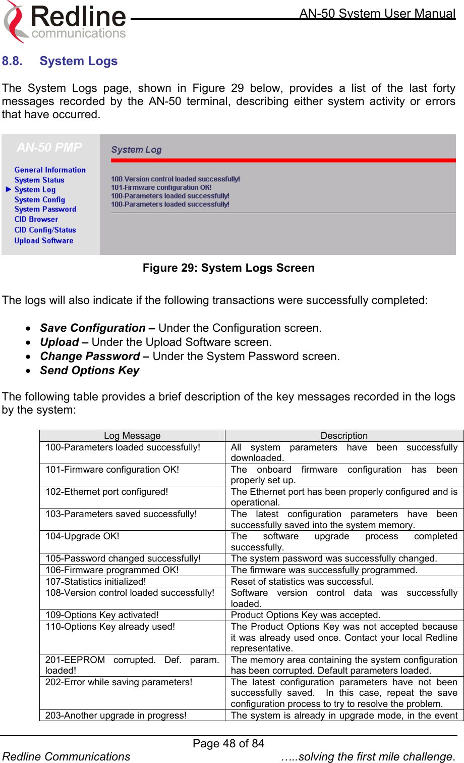
![AN-50 System User Manual Redline Communications …..solving the first mile challenge. Wireless link Status: Link Name: Displays the link name from the system memory. The name remains with the system even during power off states, until the operator re-types a new name using this menu field. Link ID: Displays the link ID automatically defined by the AN-50 System for the link name. Peer MAC: Shows the MAC address of the peer station Link Active: "Yes" indicates the RF link with the remote terminal is established. "No" indicates there is no RF link to the remote terminal. This indicator is correlated to the Wireless Link LED of the slave AN-50. Status Code: A code shown as a hex number indicating the condition of the RF components within the AN-50 terminal and T-58 Transceiver. Registered Connections: Shows the total number of connections configured for this link. For AN-50 operating in PTP mode the system will always display one (1) connection. Link Status Downlink / Uplink: Burst Rate [Mb/s]: Indicates the current master Tx burst rate. With adaptive modulation, this rate may change over time, depending on the prevailing propagation conditions. RSSI [dBm]: Indicates the average received signal strength (RSSI) at the slave remote site. SINADR [dB]: Indicates the average signal to interference noise and distortion ratio (SINADR) at slave remote site. The ratio is based on the digital information provided from the output of the A/D converter and includes the effects of the AGC. Link Statistics Downlink / Uplink: Lost Frames: Shows the total frames lost from master to slave Blocks Total: Shows the total blocks transmitted between master and slave Blocks Retransmitted: Shows the total blocks retransmitted between master and slave Blocks Discarded: Shows the total blocks lost between master and slave CID Statistics Downlink / Uplink: Packets Discarded: Indicates the total number of packets discarded due a full buffer full Packets Transmitted: Indicates the total number of packets transmitted by the master unit Page 40 of 84](https://usermanual.wiki/Redline-Communications/AN50S.users-manual/User-Guide-311130-Page-40.png)
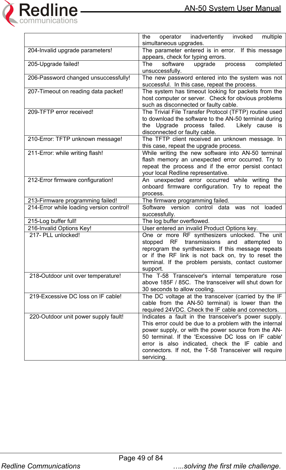
![AN-50 System User Manual Redline Communications …..solving the first mile challenge. 8.4. General Information Figure 24: AN-50 General Information Located at the top of this page is a graphic interface providing a real-time synoptic view of the AN-50 terminal front panel (refreshed every 30 sec.), plus a summary of general information related to the configuration and status of the local unit. The following is a brief description of each field on the General Information page: System: System Name: Identifies the local terminal. The factory default name for the system is “WEB01”. System Details: Specifies the location, telephone number and/or contact information. Master Mode: Specifies whether the AN-50 operates in PMP / PTP master or slave. Software Version: Specifies the software version in use. Time Since System Start: Specifies the time [dd/hh/mm/ss] since the system started. Ethernet: Ethernet MAC Address: Specifies the Ethernet MAC address used by the local terminal. IP Address: Specifies the IP address used by the local terminal. Page 42 of 84](https://usermanual.wiki/Redline-Communications/AN50S.users-manual/User-Guide-311130-Page-42.png)
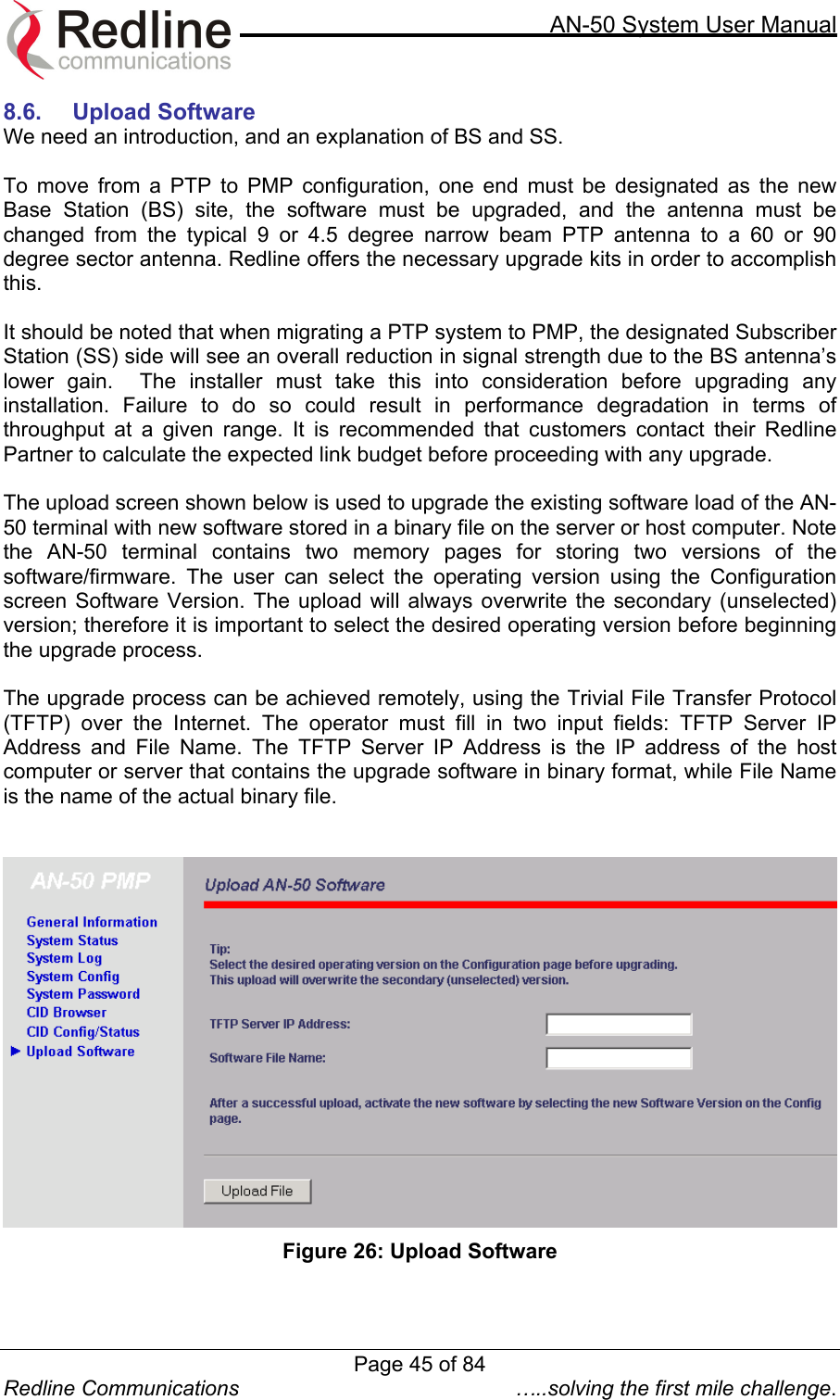
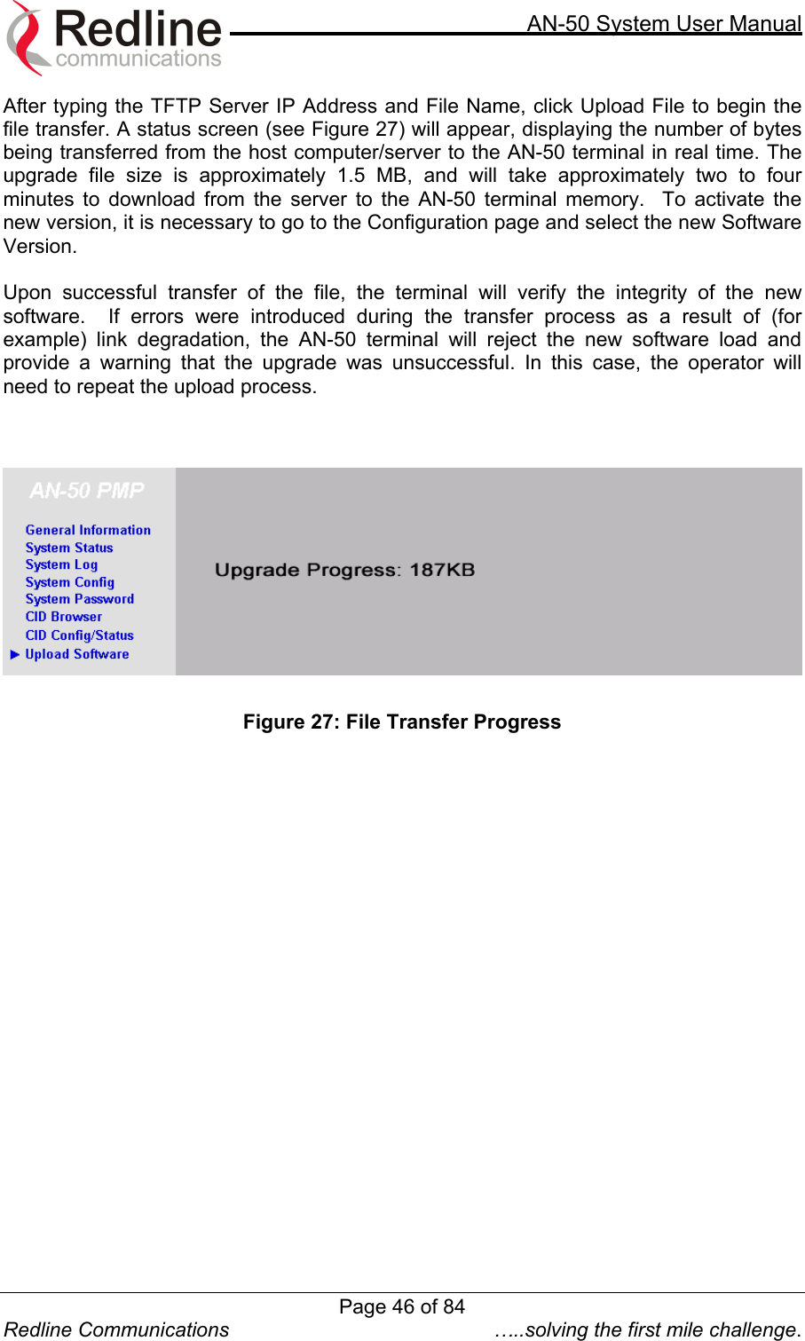
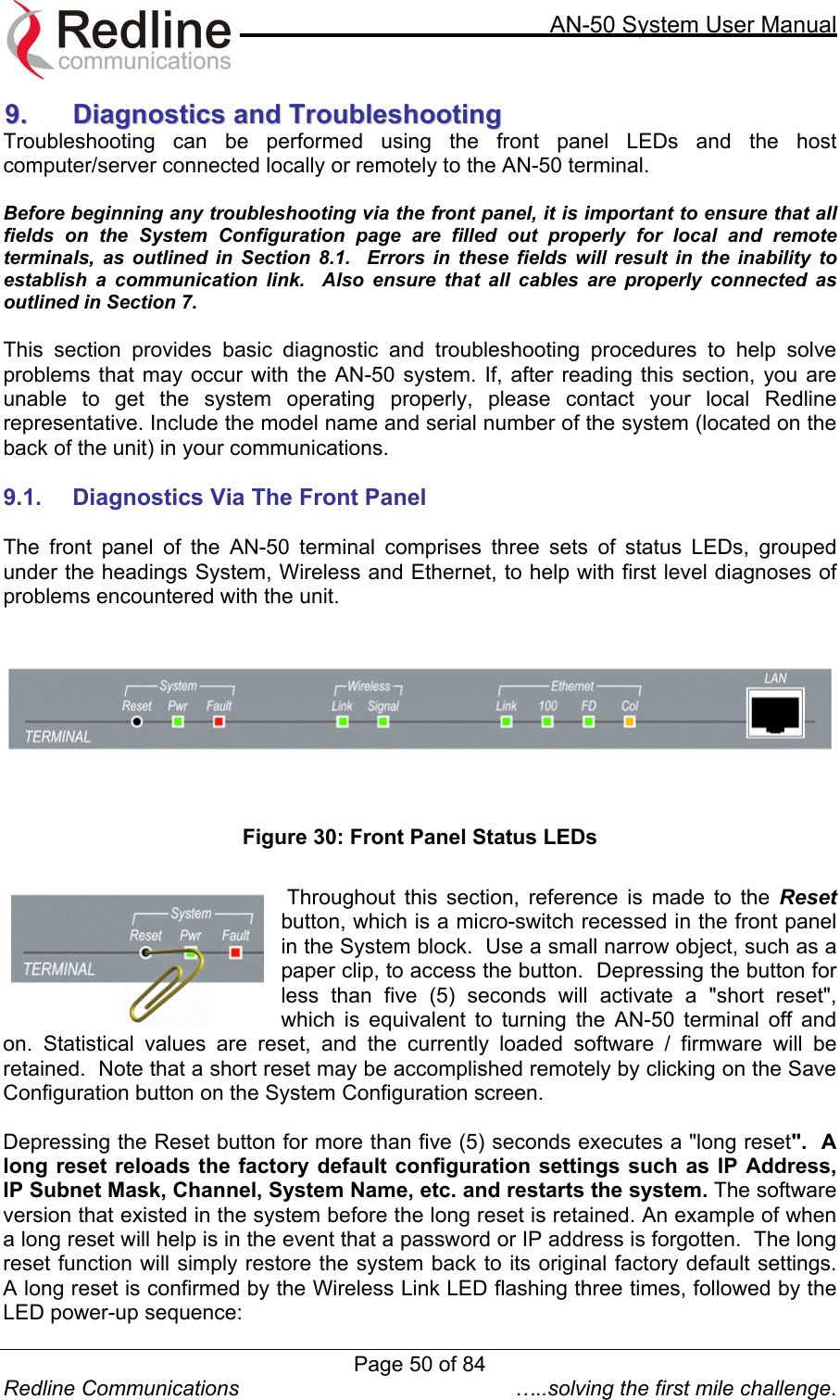
![AN-50 System User Manual Redline Communications …..solving the first mile challenge. 8.5. System Status Clicking on System Status in the main menu will load this page, which provides General Information, Ethernet LAN Statistics and Wireless Statistics of the unit of interest, as shown in Figure 25. Figure 25: System Status System Status: RF Status [Error Code]: An error code indicating the condition of the RF components within the AN-50 terminal and T-58 Transceiver. See error list below for details: AN-50 PLL Error: The PLL (Phase Locked Loop) section within the AN-50 terminal experienced an error. The System Fault LED may light. Try resetting the unit. Communication Error Over IF Cable: Communication between the AN-50 terminal and the T-58 Transceiver failed. Check the IF cable and connectors. Radio High Temp. Warning: The T-58 Transceiver’s internal temperature rose above 185F / 85C. The transceiver will shut down for 30 seconds to allow cooling time. Radio Power Supply Fault: Indicates a fault in the transceiver’s power supply. This error could be due to a problem with the internal power supply, or with the power source from the AN-50 terminal. If the Low DC Voltage At Radio error is also indicated, (see below) check the IF cable and connectors. If the Low DC Voltage At Radio error is not indicated, the T-58 Transceiver will require servicing. Low DC Voltage At Radio Input: The DC voltage at the transceiver (carried by the IF cable from the AN-50 terminal) is lower than the required 24VDC. Check the IF cable and connectors. The minimum required voltage for operation is 12VDC. Cable Attenuation: Indicates the attenuation of the signal over the IF cable. Registered Station: Shows the total number of configured links. If the AN-50 operates in PTP mode this field will display one. Page 43 of 84](https://usermanual.wiki/Redline-Communications/AN50S.users-manual/User-Guide-311130-Page-43.png)