Redline Communications AN50S AN50S Wireless Ethernet Bridge User Manual Getting Started
Redline Communications Inc. AN50S Wireless Ethernet Bridge Getting Started
Contents
- 1. users manual
- 2. FCC info to users
- 3. USERS MANUAL
users manual
Release 2.0
Manual 70-0001 Rev. 02-05

AN-50 System User Manual
Redline Communications …..solving the first mile challenge.
Redline Communications
AN-50 System User Manual
Copyright Information
This document may not in whole or in part be copied, reproduced, or reduced to any
medium without prior consent, in writing, from Redline Communications.
Disclaimer
This manual was designed to help you install, use and troubleshoot the Redline AN-50
Broadband Fixed Wireless (BFW) system. Every effort has been made to ensure the
accuracy of the material provided herein; however, Redline assumes no responsibility
regarding the use of the material. Additionally, Redline makes no representations or
warranties, either expressed or implied, regarding the contents of this product. Redline
Communications shall not be liable for any misuse regarding this product.
1.1
Page 2 of 84

AN-50 System User Manual
Redline Communications …..solving the first mile challenge.
FCC & IC Information
1 - This equipment has been tested and found to comply with the limits for a Class A
digital device, pursuant to Part 15 of the FCC Rules. These limits are designed to
provide reasonable protection against harmful interference when the equipment is
operated in a commercial environment. This equipment generates, uses, and can radiate
radio frequency energy and, if not installed and used in accordance with the instruction
manual, may cause harmful interference to radio communications. Operation of this
equipment in a residential area is likely to cause harmful interference in which case the
user will be required to correct the interference at his/her own expense.
2 - A Class A digital device is marketed for use in a commercial, industrial or
business environment, exclusive of a device which is marketed for use by the
general public or is intended to be used in the home.
3 - Intentional or unintentional changes or modifications not expressly approved by the
party responsible for compliance must not be made. Any such modifications could void
the user’s authority to operate the equipment and will void the manufacturer’s warranty.
Contact Information
Redline Communications Inc.
90 Tiverton Court,
Suite 102
Markham, ON
Canada L3R 9V2
Web site: http://www.redlinecommunications.com
Sales Inquiries:
North American – nainfo@redlinecommunications.com
International – intlinfo@redlinecommunications.com
Toll-free sales line – 1-866-633-6669
Support:
Email – support@redlinecommunications.com
Toll-free support line - 1-866-999-3537
Product Registration / Product Options:
http://www.redlinecommunications.com
Click on ‘Support’ User ID: Register Password: Redline
Comments or suggestions concerning this manual may be e-mailed to the support
team.
Page 3 of 84

AN-50 System User Manual
Redline Communications …..solving the first mile challenge.
TABLE OF CONTENTS
1. Getting Started .......................................................................................................... 8
1.1. How To Use This Manual ..................................................................................8
1.2. AN-50 System Overview ................................................................................... 8
2. Important Safety Information...................................................................................10
3. Important Service Information ................................................................................. 12
4. Unpacking the AN-50 System ................................................................................. 13
5. AN-50 System Mode of Operation .......................................................................... 14
6. The AN-50 Terminal at a Glance............................................................................. 16
6.1. The AN-50 System’s T-58 Transceiver / Antenna at a Glance ....................... 19
7. AN-50 System Installation.......................................................................................20
7.1. General Site Survey ........................................................................................ 21
7.2. Installing The Antenna..................................................................................... 22
7.3. Running The IF Cable .....................................................................................24
7.4. Installing The Terminal ....................................................................................26
7.5. Aligning The Antenna ...................................................................................... 28
8. System Configuration and Operation Via the Web Interface................................... 30
8.1. Configuration ................................................................................................... 32
8.2. CID Configuration and Status.......................................................................... 36
8.2.1. Link Configuration.................................................................................... 37
8.2.2. Wireless Link Status ................................................................................ 39
8.3. CID Browser ....................................................................................................41
8.4. General Information......................................................................................... 42
8.5. System Status ................................................................................................. 43
8.6. Upload Software.............................................................................................. 45
8.7. System Password............................................................................................ 47
8.8. System Logs.................................................................................................... 48
9. Diagnostics and Troubleshooting............................................................................ 50
9.1. Diagnostics Via The Front Panel.....................................................................50
9.1.1. System Power ......................................................................................... 51
9.1.2. System Fault............................................................................................ 52
9.1.3. Wireless Link ........................................................................................... 52
9.1.4. Wireless Signal........................................................................................53
9.1.5. Ethernet Link ...........................................................................................53
9.1.6. Ethernet Collision ....................................................................................54
9.2. Troubleshooting The Web Interface ................................................................ 55
9.3. Broadband Fixed Wireless Primer................................................................... 56
9.4. Deployment Scenarios .................................................................................... 57
9.5. Who Can Benefit From The AN-50 System?................................................... 59
9.6. The AN-50 Advantage..................................................................................... 62
9.7. Wireless Facts.................................................................................................63
9.7.1. The Link Budget Tool ..............................................................................63
10. Glossary Of Terms .............................................................................................. 70
11. Appendix 3 – Support For TDM Using Third Party Units..................................... 72
12. Specifications ...................................................................................................... 73
12.1. AN-50 System Specifications ...................................................................... 73
12.2. Nine Degree Antenna Specifications........................................................... 75
12.3. Four Point Five Degree Antenna Specifications.......................................... 76
12.4. Sixty Degree Antenna Specifications .......................................................... 77
Page 4 of 84

AN-50 System User Manual
Redline Communications …..solving the first mile challenge.
12.5. Ninety Degree Antenna Specifications........................................................78
12.6. Vertical Mount Dimensions.......................................................................... 79
12.7. Universal Mount Dimensions....................................................................... 80
12.8. Vertical Mount Assembly.............................................................................81
12.9. Universal Mount Assembly..........................................................................83
Page 5 of 84

AN-50 System User Manual
Redline Communications …..solving the first mile challenge.
LIST OF TABLES
Table 1: System Power Diagnostics ...............................................................................51
Table 2: Wireless Link Diagnostics ................................................................................. 52
Table 3: Wireless Signal Diagnostics.............................................................................. 53
Table 4: Ethernet Link Diagnostics ................................................................................. 54
Table 5: Ethernet Collision Diagnostics .......................................................................... 54
Table 6: Web Interface Diagnostics ................................................................................ 55
Table 7: Modulation Scheme vs. Data Rate................................................................... 64
Table 8: Availability Versus Outage Time ....................................................................... 66
Table 9: Radar Horizon Ranges For Different Terminal Heights (H1 and H2) ................. 69
Page 6 of 84

AN-50 System User Manual
Redline Communications …..solving the first mile challenge.
LIST OF FIGURES
Figure 1: The AN-50 System Out Of The Box.................................................................13
Figure 2: Available Antenna Options............................................................................... 13
Figure 3: Front Panel – System ...................................................................................... 16
Figure 4: Front Panel - Wireless ..................................................................................... 17
Figure 5: Front Panel – Ethernet..................................................................................... 17
Figure 6: LAN Interface................................................................................................... 18
Figure 7: AN-50 Radio With Universal Mount ................................................................. 19
Figure 8: AN-50 Radio With Vertical Mount .................................................................... 19
Figure 9: AN-50 System Installation................................................................................ 20
Figure 10: Radio Deployment Options ............................................................................ 22
Figure 11: IF Cable ......................................................................................................... 24
Figure 12: AN-50 Terminal Connected To Switch / Router / Hub ................................... 26
Figure 13: AN-50 Terminal Connected To Host Computer ............................................. 27
Figure 14: AN-50 Terminal LAN Ethernet Port Pinout ....................................................27
Figure 15: Aligning The Antenna – Universal Mount....................................................... 28
Figure 16: Aligning The Antenna - Vertical Mount .......................................................... 28
Figure 17: User Name And Password Dialog .................................................................31
Figure 18: System Configuration..................................................................................... 32
Figure 19: CID Config / Status ........................................................................................ 36
Figure 20: Link Configuration.......................................................................................... 38
Figure 21: Wireless Link Status ...................................................................................... 39
Figure 22: CID Browser................................................................................................... 41
Figure 23: CID Browser Results...................................................................................... 41
Figure 24: AN-50 General Information ............................................................................ 42
Figure 25: System Status................................................................................................ 43
Figure 26: Upload Software ............................................................................................ 45
Figure 27: File Transfer Progress ................................................................................... 46
Figure 28: System Password .......................................................................................... 47
Figure 29: System Logs Screen...................................................................................... 48
Figure 30: Front Panel Status LEDs ............................................................................... 50
Figure 31: Cell Sectorization........................................................................................... 57
Figure 32: Growing a Network ........................................................................................58
Figure 33: Hybrid PTP/PMP............................................................................................ 58
Figure 34: Single Sector PMP Deployment..................................................................... 59
Figure 35: Wireless Extension for Carriers ..................................................................... 60
Figure 36: Wireless Solution For ISPs ............................................................................ 60
Figure 37: Wireless Solution For Enterprise ................................................................... 61
Figure 38: Wireless Solution for MTUs ...........................................................................61
Figure 39: Fresnel Zone Obstruction .............................................................................. 64
Figure 40: Fresnel Zone Radius Calculation................................................................... 65
Figure 41: Link Budget For 64 QAM ¾ Code Rate ........................................................ 67
Figure 42: Fade Margin Graphs For LOS, OLOS and NLOS.......................................... 68
Page 7 of 84

AN-50 System User Manual
Redline Communications …..solving the first mile challenge.
1
1.
.
G
Ge
et
tt
ti
in
ng
g
S
St
ta
ar
rt
te
ed
d
1.1. How To Use This Manual
This User Manual is designed to get you started using the Redline Communications
Access Node-50 (AN-50) Broadband Fixed Wireless (BFW) system by guiding you
through the step-by-step process of setting up the system for the first time.
To that end, the following principal steps will need to be followed in order:
1. Review the safety and service information (Sections 2 and 3 of this manual)
2. Unpack the AN-50 system (Section 4)
3. Install the outdoor radio (transceiver plus antenna) (Section 7)
4. Install the indoor terminal (Section 7)
5. Configure the system via a host computer and web browser interface (Section 8)
6. Ensure the Mac address of the remote AN-50 has been properly configured (see
Section 8.2.1) on the local unit
7. Install the 64 QAM license key high speed option (page 8.1)
This User Manual will also help with the following:
• Understanding Fixed Wireless Systems
• Referencing AN-50 System Specifications
• Troubleshooting the System
1.2. AN-50 System Overview
The AN-50 is a high-performance, high-speed wireless Ethernet bridge that provides a
scalable platform for the deployment of multi-services over a common equipment
infrastructure and management system. The AN-50 System can operate in a Point-To-
Point (PTP) or Point-To-Multipoint (PMP) mode depending on the software configuration.
In PTP mode, only two stations can communicate with each other, while the PMP mode
consists of one or more Subscriber Station(s) that communicate with the Base Station.
For complete procedures on software upgrade and use of the option key please refer to
sections 8.1 and 8.6.
The AN-50 system operates in the unlicensed band of 5.8 GHz and includes advanced
technologies to address any potential inter-cell interference issues. The system also
features adaptive modulation in both directions for automatic selection of modulation
schemes, including BPSK, QPSK, 16 and 64 QAM to maximize data rate, and hence
spectral efficiency. Additionally, the system delivers enhanced security through a
proprietary, over the air, 128 bit encryption scheme that significantly improvesthe privacy
and integrity of all traffic.
Page 8 of 84

AN-50 System User Manual
Redline Communications …..solving the first mile challenge.
The AN-50 can be equipped with a narrow beam antenna to provide high directivity for
long-range operations beyond 50 miles (80 km) in line of sight (LOS) conditions, and up
to 6 miles (10 km) in NLOS conditions. The AN-50 using wide beam antennas
associated with the PMP mode of operation can operate 5-7 miles, depending on power
limits mandated by regional regulation.
The AN-50 system is a Class A digital device for use in a commercial, industrial or
business environment.
Page 9 of 84

AN-50 System User Manual
Redline Communications …..solving the first mile challenge.
2
2.
.
I
Im
mp
po
or
rt
ta
an
nt
t
S
Sa
af
fe
et
ty
y
I
In
nf
fo
or
rm
ma
at
ti
io
on
n
1 Read this User Manual and follow all operating and safety instructions.
2 Keep all product information for future reference.
3 This product is supplied with a grounding power plug. Do not defeat this important
safety feature.
4 The power requirements are indicated on the product-marking label. Do not exceed
the described limits.
5 Always replace the fuse with the correct type and current rating.
6 Position the power cord to avoid possible damage, and do not overload wall outlets.
7 Do not place this product on or near a direct heat source, and avoid placing objects
on the terminal.
8 Do not operate this device near water or in a wet location.
9 Use only a damp cloth for cleaning. Do not use liquid or aerosol cleaners.
Disconnect the power before cleaning.
10 Protect the unit by disconnecting the power if it is not used for long periods of time.
11 Locate the AN-50 terminal on a stable horizontal surface or mount it securely in a
19” Telco rack.
12 The T-58 Transceiver unit must not be located near power lines or other electrical
power circuits.
13 The T-58 Transceiver must be properly grounded to protect against power surges
and accumulated static electricity. It is the user’s responsibility to install this device
in accordance with Section 810 of the National Electrical Code, ANSI/NFPA No. 70-
1984 or Section 54 of the Canadian Electrical Code. These codes describe correct
installation procedures for grounding of the transceiver unit, mast, lead-in wire and
discharge unit, location of discharge unit, size of grounding conductors and
connection requirements for grounding electrodes. It is recommended that the
installation of the transceiver be contracted to a professional installer.
Page 10 of 84
AN-50 System User Manual
Redline Communications …..solving the first mile challenge.
The following symbols may be encountered during installation or troubleshooting. These
warning symbols mean danger. Bodily injury may result if you are not aware of the safety
hazards involved in working with electrical equipment and radio transmitters. Familiarize
yourself with standard safety practices before continuing.
Electro-Magnetic Radiation
High Voltage
Page 11 of 84

AN-50 System User Manual
Redline Communications …..solving the first mile challenge.
3
3.
.
I
Im
mp
po
or
rt
ta
an
nt
t
S
Se
er
rv
vi
ic
ce
e
I
In
nf
fo
or
rm
ma
at
ti
io
on
n
1 Refer all repairs to qualified service personnel. Do not remove the covers or modify
any part of this device, as this will void the warranty.
2 Disconnect the power to this product and return it for service if the following
conditions apply:
a) The unit does not function after following the operating instructions outlined in this
manual.
b) Liquid has been spilled, a foreign object is inside or the AN-50 terminal has been
exposed to rain.
c) The product has been dropped or the housing is damaged.
3 Locate the serial number of the AN-50 Terminal, Antenna, and T-58 Transceiver
and record these on your registration card for future reference. Use the space below
to affix serial number stickers. Also record the MAC address, located on the back of
the AN-50 Terminal.
Product Information
AN-50 Terminal SN:_________________ AN-50 Terminal MAC Address:_________________
T-58 Transceiver SN:_______________________ Model #: ___________________________
Antenna Type:_____________________ Antenna SN:________________________________
Serial Number Stickers
Page 12 of 84
AN-50 System User Manual
Redline Communications …..solving the first mile challenge.
4
4.
.
U
Un
np
pa
ac
ck
ki
in
ng
g
t
th
he
e
A
AN
N-
-5
50
0
S
Sy
ys
st
te
em
m
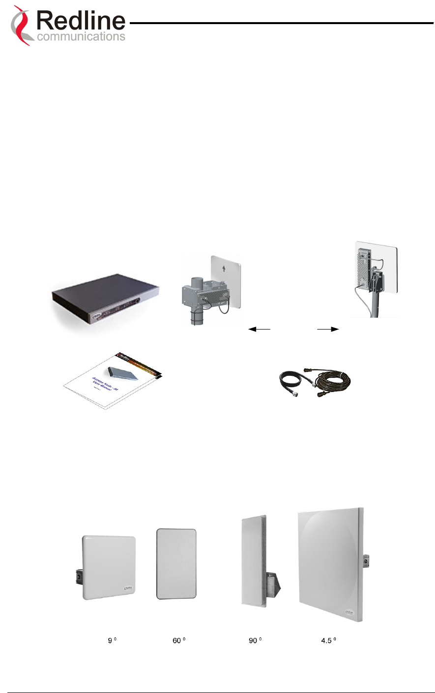
The AN-50 system comes packaged with the following major items (refer to Figure 1 for
a pictorial view):
• AN-50 terminal (indoor unit)
• AN-50 Radio (outdoor unit):
T-58 Transceiver
Antenna (4.5, 9, 60 or 90 degree)
• Antenna Mounting Bracket:
Vertical (accommodates 4.5, 9, 60 and 90 degree antennas)
Universal (accommodates 9 degree antenna)
• Power Cord and outdoor IF Cable (100 ft. / 30.5 m)
• User Manual
AN-50 Terminal
Universal
Mount
AN-50 Radio
Power/IF
Cables
V
ertical
Mount
User Manual
A
ntenna
Mounting
Options
Figure 1: The AN-50 System Out Of The Box
A complete list of items included in the system is available on the packing list included
with the system. Note that a complete list of FCC approved antennas can be found on
the Redline WEB site under SUPPORT.
Figure 2: Available Antenna Options
Page 13 of 84

AN-50 System User Manual
Redline Communications …..solving the first mile challenge.
5
5.
.
A
AN
N-
-5
50
0
S
Sy
ys
st
te
em
m
M
Mo
od
de
e
o
of
f
O
Op
pe
er
ra
at
ti
io
on
n
The AN-50 system utilizes Redline’s advanced Medium Access Control (MAC) design to
provide efficient transmission of data in both PTP and PMP modes. In PMP mode, the
MAC incorporates a proprietary polling algorithm to support up to 1024 individual
subscriber stations from a single base station operating in a single sector. Note that
multiple base stations can be installed on a single roof-top or tower to provide multi-
sector coverage.
A single sector AN-50 PMP implements a distributed wireless L2 switch, with one uplink
port located on the sector controller (master) distributing bandwidth to a variable number
of subscriber stations (slaves).
• Each subscriber station (or slave) is considered a separate wireless link.
• Each configured wireless link adds to the switch one slave port that is the
Ethernet port on the corresponding subscriber station. This is achieved
during provisioning.
• Each link (slave port) is assigned one Connection ID (CID) that is used to
manage both the connection traffic and the wireless link, thus the Link ID
(LID) is equal to the CID.
• The switch supports one broadcast/multicast group called default group.
• The default group is assigned automatically to a fixed CID.
• The switch supports up to 1024 CIDs and consequently up to 1024 slave
ports and subscriber stations.
The AN-50 MAC utilizes a request/grant polling mechanism to determine which
subscriber station requires bandwidth. This is achieved by periodically polling each
subscriber station to determine if there is a request for bandwidth. If the SS requests
bandwidth then the MAC allocates the appropriate number of time slots, in both the
downstream and upstream direction, in accordance with the quality of service (QoS) rate
limits specified for that particular SS. The QoS parameters define the minimum and
maximum rates allowed for each SS through two parameters, Committed Information
rate (CIR) and Peak Information rate, respectively. Note that a CIR of zero (0) implies no
QoS, and is referred to as Best Effort (BE) services. To improve bandwidth efficiency,
the MAC keeps track of all inactive subscriber stations (i.e. those not requesting
bandwidth for a certain period of time) and polls them less frequently compared to those
units that are actively passing traffic. Units that are inactive are considered to be in
‘sleep’ mode. When a unit exits from sleep mode (i.e., it enters into the network), the
MAC will resume a quicker polling profile for that unit to ensure bandwidth requests are
granted in sufficient time.
With multiple subscriber stations vying for bandwidth, the MAC ensures that time slots
are allocated in a balanced manner, according to QoS levels, during periods of over-
subscription. For example, during peak times, the MAC will first deny time slot
allocations to those units with no QoS (BE), and then reduce bandwidth in a proportional
manner to the remaining units with varying QoS priorities. With QOS, the service
provider can offer different grades of service to each end user in a controlled manner
based on their service level agreements or contracts. Note that QoS can also be applied
Page 14 of 84

AN-50 System User Manual
Redline Communications …..solving the first mile challenge.
to the PTP configuration, for deployment scenarios where the service provider wishes to
control the amount of bandwidth offered to the end user.
Page 15 of 84
AN-50 System User Manual
Redline Communications …..solving the first mile challenge.
6
6.
.
T
Th
he
e
A
AN
N-
-5
50
0
T
Te
er
rm
mi
in
na
al
l
a
at
t
a
a
G
Gl
la
an
nc
ce
e
The front panel of the AN-50 terminal includes a LAN interface and three main status
indicators; System, Wireless, and Ethernet. The rear of the terminal includes the power
cord connector and an F-Type female connector for the IF cable.
At power up, an LED power-up sequence occurs as follows:
All four Ethernet LEDs light for one second, then individual Ethernet LEDs blink twice in
the following order: 100, FD, Col, Link. The Fault LED lights for approximately four
seconds, then turns off. The two Wireless LEDs remain off for approximately five
seconds, then blink once and resume their normal state.
For a detailed description of the status indicators on the front panel, see the Diagnostics
section of this manual, Section 9.1 on page 50.
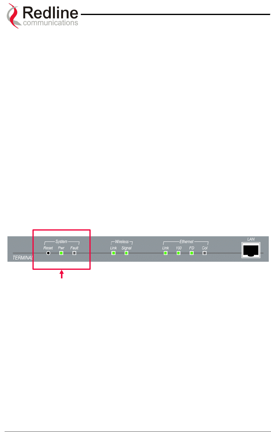
A) System Status Indicators
The System portion of the front panel features a recessed reset switch and two LEDs
(Pwr and Fault), as shown in the figure below.
Figure 3: Front Panel – System
Reset – The system can be manually hard reset by depressing the “Reset” button
recessed in the front panel. The reset button is used to reactivate the terminal in the
event that it is functioning improperly or is in a state of suspension.
Pwr – The “Pwr” LED lights solid green when the AC power is properly applied to the
terminal. In the event of internal power supply failure, if the cord is disconnected, or if
the fuse is blown, the “Pwr” light will not illuminate.
Fault – The “Fault” LED lights solid red when a serious fault is detected within the
system.
Page 16 of 84
AN-50 System User Manual
Redline Communications …..solving the first mile challenge.
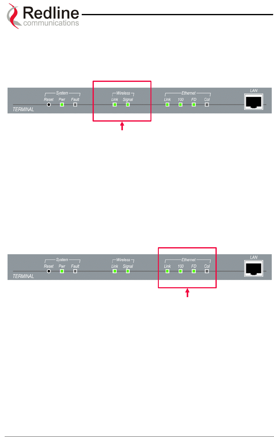
B) Wireless Status Indicators
The Wireless portion of the front panel features two LEDs; Link and Signal, as shown
below.
Figure 4: Front Panel - Wireless
Link – The “Link” LED lights solid green when the radio link to the remote terminal is
established. The LED will turn off if the link is lost.
Signal – The “Signal” LED lights solid green if the system is operating at the configured
Uncoded Burst Rate. See section 9.1.4 on page 53 for a detailed description.
C) Ethernet Status Indicators
The Ethernet portion of the front panel display comprises four main LEDs; Link, 100, FD
and Col, as shown below.
Figure 5: Front Panel – Ethernet
Link – The “Link” LED illuminates solid green when the Local Area Network (LAN)
connection is established, and there is no traffic. The Link LED will flash when the Local
Area Network (LAN) connection is established, and there is traffic.
Page 17 of 84
AN-50 System User Manual
Redline Communications …..solving the first mile challenge.
100 – The “100” LED lights solid green when the Ethernet port is operating at 100 Mb/s.
The LED will not illuminate if the port is operating in 10 Mb/s mode. The Ethernet port
automatically selects the speed through auto-negotiation with either the host
computer/server or router/switch.
FD – The “FD” LED illuminates solid green when the LAN connection is operating in Full
Duplex mode. The system automatically selects the duplex mode through auto-
negotiation with the host computer or switch.
Col – The “Col” LED flashes in amber when collisions are detected on the Ethernet port.
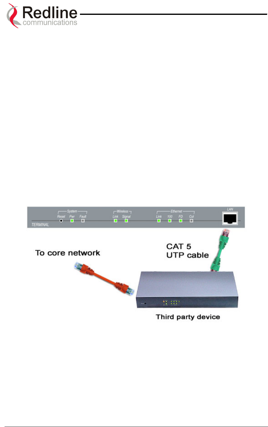
D) The LAN Interface
The LAN interface is a 10/100 BaseT Ethernet port, which is used to connect the AN-50
terminal to either the core network or to a host computer. A router or switch is often used
to complete the connection to the core network, as shown in the figure below. Note that
different cables are required for connection to a hub/switch/router or host computer. See
Section 7.4 of this manual for more information regarding installation of the terminal.
Figure 6: LAN Interface
Page 18 of 84
AN-50 System User Manual
Redline Communications …..solving the first mile challenge.
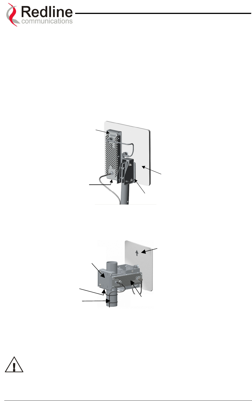
6.1. The AN-50 System’s T-58 Transceiver / Antenna at a Glance
Either a Universal mount (as shown in Figure 7) or Vertical mount bracket (Figure 8) is
provided with the system.
The Universal mount features a bracket to mount onto a 1¾” (4.45 cm) diameter pole.
This pole is approximately three feet (90 cm) in length and features a curve profile to
facilitate protruding building infrastructures, such as eaves. The mounting bracket at the
bottom of the pole is used to attach the antenna to the side of a building, etc.
Flat
Plate
Antenna
T-58 Transceiver
AN-50 Radio
Ground Screw
Mount Bracket
Figure 7: AN-50 Radio With Universal Mount
Ground
Screw
Flat Plate
Antenna
T-58 Transceiver
Mount
Bracket
Pole
Figure 8: AN-50 Radio With Vertical Mount
The vertical mount bracket can accommodate 1 ¾” to 4 ½” (4.45 cm – 11.45 cm) OD
masts found on many commercial tower installations.
Before connecting the AN-50 system, it is important to review the safety
tips provided at the beginning of this manual.
Page 19 of 84
AN-50 System User Manual
Redline Communications …..solving the first mile challenge.
7
7.
.
A
AN
N-
-5
50
0
S
Sy
ys
st
te
em
m
I
In
ns
st
ta
al
ll
la
at
ti
io
on
n
This section of the manual presents a basic overview of the steps required to install the
AN-50 terminal, outdoor transceiver, antenna and associated equipment.
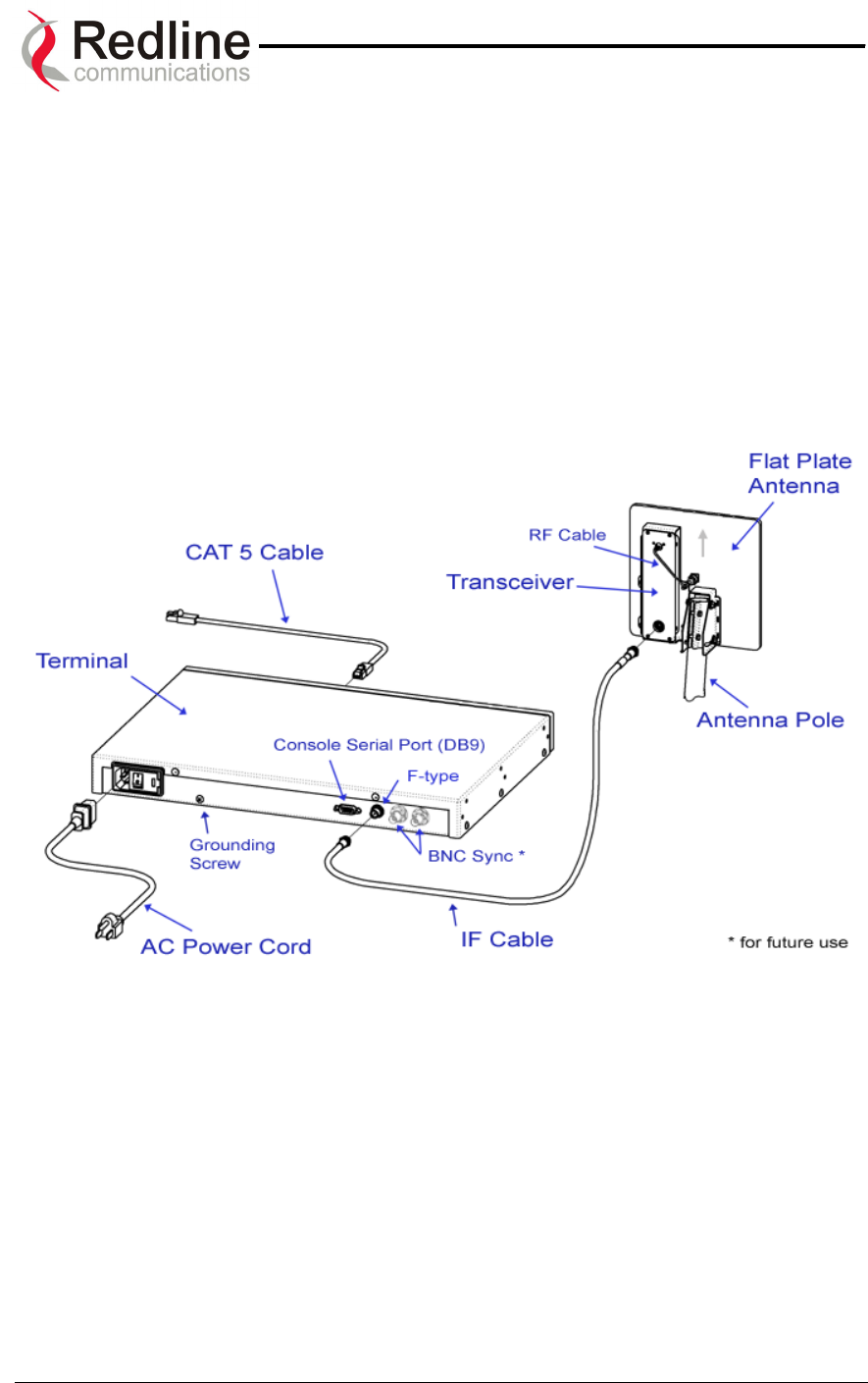
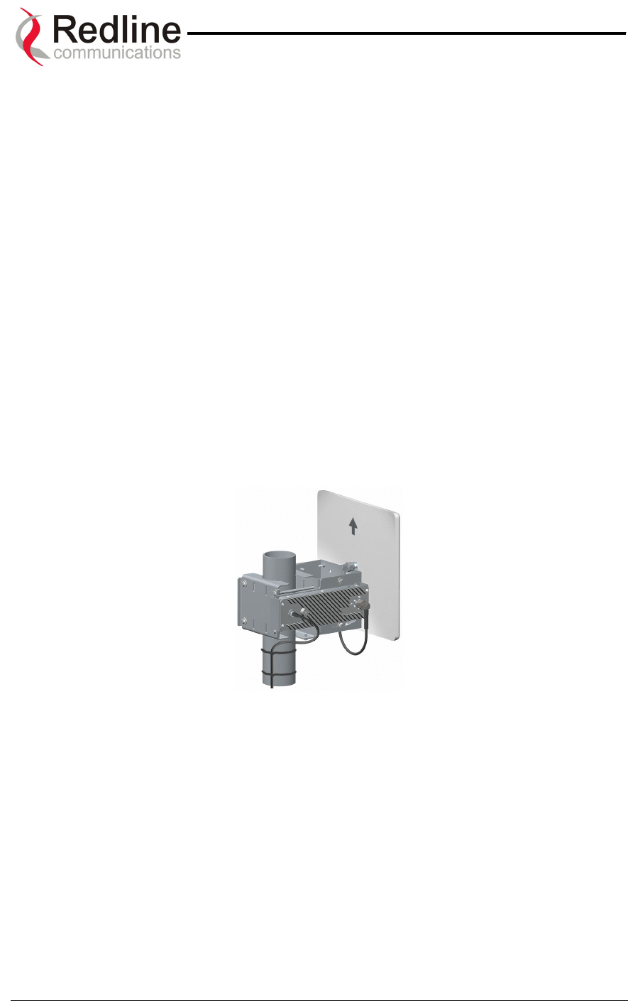
Figure 9 below illustrates the primary system components and cables. The power cord
connects to a 110/220/240 VAC standard power outlet, while the CAT 5/UTP cable (not
included) connects the terminal to the data network via a standard 10/100BaseT
Ethernet connection. The provided IF cable connects the terminal (located indoors) to
the T-58 Transceiver (located outdoors), and carries the transmitted and received signal,
DC power for the AN-50 radio, as well as control and reference signals. Note that the
provided IF cable is meant for exterior use, and should be used for only minimal interior
runs to connect to the terminal. Also note that the BNC connectors are for future use.
Figure 9: AN-50 System Installation
The terminal is for indoor installation only, while the transceiver and antenna (together
known as the AN-50 Radio) are mounted externally. The principal steps in installation
are:
1. Conduct a general site survey
2. Install the antenna
3. Install the IF cable
4. Install the AN-50 terminal
5. Align the antenna
Each step is addressed in more detail below.
Page 20 of 84

AN-50 System User Manual
Redline Communications …..solving the first mile challenge.
7.1. General Site Survey
The first step in installing the AN-50 system is to conduct a general site survey.
Although the installation steps are relatively straightforward, they do involve some
construction and electrical work, which is best performed by a professional installer.
The following site survey steps should be followed:
Determine the optimum location. The first key step in the deployment exercise is to
determine and identify building candidates that can be used to support the link. A critical
parameter to consider is the range at which the subscriber station, base station or
terminals are required to operate. Range performance is determined by empirical
formulas that consider a number of equipment and environmental factors described in
Section 9.7 of this manual. Ensure that the installation sites meet these range
performance requirements before moving to the next step. You may use Redline’s Link
Budget Tool to determine the expected performance of the link. The Link Budget Tool
can be obtained by contacting your Redline certified partner or system integrator. See
Section 9.7.1 on page 63 for more information.
Verify the accuracy of any building drawings/blueprints that may be available. The
installation process may require penetrating the building to run the IF cable between the
outdoor and indoor units. In this regard, it is imperative that the blueprints and/or
drawings of the building are up to date and accurate. It may also be possible for the IF
cable to be installed on the outside of the building leading to the antenna location on the
roof of the building.
Identify the best path for the link. For maximum performance, it is recommended to
mount the antenna in a location where there is line of sight to the remote terminal. If
possible, the antenna should be positioned such that there is maximum clearance within
the first Fresnel zone of the direct path. Refer to Section 9.3 for a full description of
Fresnel zone clearance and its impact on signal propagation. The best means of
achieving Fresnel zone clearance is to mount the antennas as high as possible, on
either a tall building or tower, as shown in Figure 10 (Vertical mount system is shown).
The AN-50 system is also designed to operate in non-line-of-sight (NLOS) conditions, as
a result of the OFDM technology incorporated in the platform. Under NLOS conditions,
the best method of obtaining a proper RF link is to evaluate different antenna
orientations and choosing the one that results in the best Signal to Noise (SINADR) ratio
and highest Received Signal Strength (RSSI) value. Often, this can be achieved by
introducing an RF multipath condition by orienting the antennas towards a structure in
sight of both the local and remote antennas. If the obstruction in the path is not
exceptionally high, it may be possible to aim both antennas near the top of the
obstruction. With the use of OFDM in the Redline system, any additional multipath
signals introduced will provide additional opportunities for an improved link. For PTP and
Subscriber Station it is very important that the above steps are carefully fallowed. For the
Base Station the accuracy of the aiming is not so important as the antenna is using a
wide angle.
Page 21 of 84

AN-50 System User Manual
Redline Communications …..solving the first mile challenge.
Radio
Deployments
Figure 10: Radio Deployment Options
Identify potential sources of RF interference. Test for possible RF interference on the
roof-top or tower by utilizing appropriate test equipment. RF interference arises from any
other wireless system operating within the same frequency band as the AN-50. Note
that the AN-50 system supports nine different overlapping channels within the UNII band
and has the ability to use up to five of these channels at any one cell site; there is,
therefore, some flexibility in addressing or avoiding interference should other
transmitters in relatively close proximity present problems.
7.2. Installing The Antenna
Once the site survey has been completed and the exact location for the antenna
identified, the next step is to assemble and mount the radio onto a building structure,
pole or tower.
Note there is an arrow on the back of the antenna, which must point in the same
direction for both the local and remote systems to ensure proper polarization when the
antenna is deployed (see Figure 9 above). Ensure the proper polarization is used for the
antenna before attaching the mounting bracket in the next step.
The universal or vertical mount bracket is installed first. The antenna and mounting
brackets have been designed to withstand strong winds; it is imperative that all hardware
for the mounting brackets be securely fastened to avoid any movement, which could
introduce misalignment.
Page 22 of 84

AN-50 System User Manual
Redline Communications …..solving the first mile challenge.
The T-58 Transceiver is then mounted to the mounting bracket as shown in Figure 15
and Figure 16. This assembly is in turn attached to the back of the antenna. Note the
transceiver must be connected to the antenna via the short RF cable provided.
For building mounts, ensure the surface to which the mounting bracket will be attached
is structurally sound, flat and vertical (use a level). Ensure that the installation can
withstand wind loading.
Page 23 of 84
AN-50 System User Manual
Redline Communications …..solving the first mile challenge.
7.3. Running The IF Cable
The system is shipped with a 100 foot (30.5 m) length of RG6 IF cable to connect the
transceiver and indoor terminal. The IF cable carries the transmitted and received
signal, DC power for the AN-50 radio, and control signals. One hundred feet is the
mandatory minimum length; if a longer outdoor run is required, it is recommended that a
single length of the appropriate cable be used; coupling the provided 100-foot cable to
another length will result in increased attenuation. Refer to the cable requirements in the
Specifications section at the end of this manual.
Note: If male “F” crimp connectors are used with custom cables, the cable’s core conductor
diameter must be no larger than 1mm (.042 inches) or longer than 1cm (0.38 inches) to avoid
damage to the T-58 and AN-50 connectors. If the core diameter exceeds 1mm, use solder type
‘F’ connectors that do not exceed these dimensions.
The following steps define the cable installation process:
1. Run the cable alongside the antenna pole as shown. The IF cable is equipped
with 75 ohm male F-type connectors at both ends. Ensure the cable is running
downward as shown to prevent water from accumulating on the connector. The
cable should be fastened to the pole to prevent movement or damage to the
connector.
Figure 11: IF Cable
2. The RF cable should connect the antenna to the transceiver.
3. Connect the male IF cable connector to the female F-type connector on the
transceiver. The connector should then be weatherproofed with a standard
weatherproofing material for outdoor RF installations. Note that the provided IF
cable is for exterior use. It is recommended that the cable terminate at the
exterior wall using a grounding block, and that interior grade cable be used to
connect the terminal to the grounding block according to local codes. For
convenience, a grounding block is included with the AN-50 system. An optional
lightning arrestor may be used to protect the terminal and other indoor equipment
from sudden electrical surges. A suitable arrestor may be purchased through
any of Redline’s system integrators. Note that performance may be affected by
the use of other arrestors.
Page 24 of 84

AN-50 System User Manual
Redline Communications …..solving the first mile challenge.
4. Connect the IF cable to the F-type female connector located on the back of the
terminal. The connector should be tightened finger-tight and then tightened an
additional 1/8 of a turn.
Page 25 of 84
AN-50 System User Manual
Redline Communications …..solving the first mile challenge.
7.4. Installing The Terminal
Once the AN-50 terminal and the radio are connected, the terminal is ready to be
installed and configured. The Ethernet data rate is determined automatically, depending
on the type of device connected to the system.
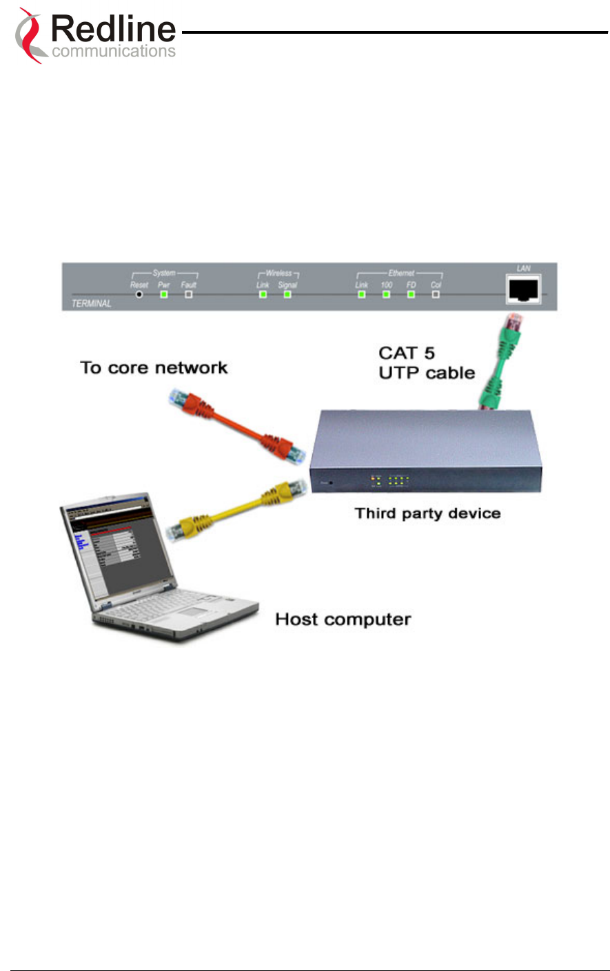
If the terminal is used for connection to a core network, the network device is likely to be
a router, hub, or switch as shown in Figure 12. In this configuration, a cross-over
Ethernet cable is required to connect between the terminal and the network device.
Figure 12: AN-50 Terminal Connected To Switch / Router / Hub
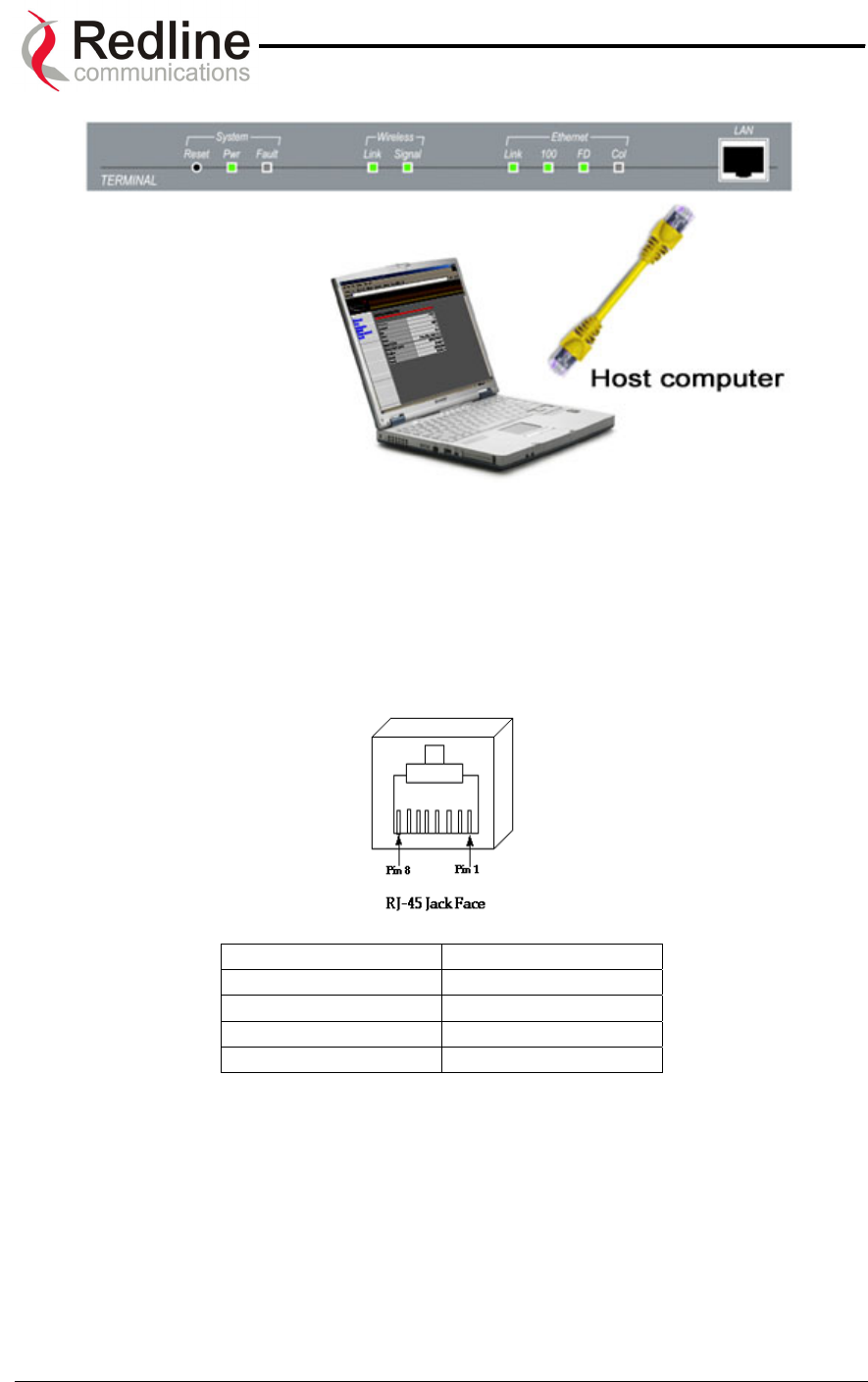
The AN-50 terminal may also be connected directly to the host computer, as shown in
Figure 13. In this configuration, a straight-through CAT 5/UTP cable is required to
complete the connection.
Page 26 of 84
AN-50 System User Manual
Redline Communications …..solving the first mile challenge.
Figure 13: AN-50 Terminal Connected To Host Computer
To help you establish other implementations that are not addressed in this manual,
Figure 14 provides an illustration of the pinout for the AN-50 terminal LAN interface.
Warning: do not connect a telephone cable to the AN-50 LAN interface, as this will
damage the terminal.
Jack Pin Function
1 Rx +
2 Rx -
3 Tx +
6 Tx -
Figure 14: AN-50 Terminal LAN Ethernet Port Pinout
Now connect the AC cord to the 110/220/240 VAC outlet and turn the terminal on using
the toggle switch at the rear of the unit. The system “Pwr” LED should illuminate green to
indicate power to the unit. The system is now ready to be configured. If the Pwr LED is
not on and/or the “Fault” LED illuminates red, there is a problem with the terminal. Refer
to the diagnostics section, Section 9 on page 50, for further details on how to address
system faults.
Page 27 of 84
AN-50 System User Manual
Redline Communications …..solving the first mile challenge.
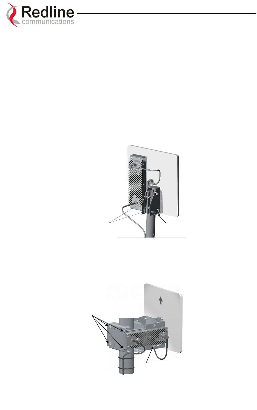
7.5. Aligning The Antenna
Once the antenna is mounted and the terminal is installed, the antenna must be aligned
in both the azimuth and elevation planes. For the base station antenna or first PTP
antenna, position the antenna in the desired direction. Elevation alignment is
accomplished by loosening the two bolts attached to the mounting bracket, as shown in
Figure 15 and Figure 16 below, and angling the antenna so it is aligned towards the
remote terminal. The azimuth alignment is accomplished by loosening the bolts on the
antenna bracket and rotating the antenna until alignment is achieved. For basic tuning
using actual signal strength, an alignment "buzzer" (intermittent tone sweep generator) is
available on the T-58 Transceiver. Faster repetitions of the tone sweep indicate better
alignment. The buzzer is enabled via the software interface described in section 8.1.
Azimuth Adjustment
Bolts Elevation
Adjustment
Figure 15: Aligning The Antenna – Universal Mount
A
zimuth Adjustment
Bolts
Elevation Adjustment
Bolts
Figure 16: Aligning The Antenna - Vertical Mount
Page 28 of 84

AN-50 System User Manual
Redline Communications …..solving the first mile challenge.
NOTICE
1 - The AN-50 System is used as a fixed wireless Ethernet bridge that requires
professional installation with specified antennas and output power levels certified under
the FCC Grant for AN-50 System for Point-to -Point or Point-to-Multipoint mode of
operations.
2 - FCC RF Exposure Requirements - The antenna(s) used for this transmitter must be
fixed-mounted on outdoor permanent structures with a separation distance of at least 2.1
meters (6.5 feet) from all persons and must not be co-located or operating in conjunction
with any other antenna or transmitter.
3 - The AN-50 System is certified by the FCC and Industry Canada with 5.8 GHz
Directional and Parabolic Antennas, listed bellow:
Redline
Antenna PN Antenna Gain Antenna Type Application
10-0007 14 dBi Directional, Flat Panel PMP
10-0006 15 dBi Directional, Flat Panel PMP
10-0004 23 dBi Directional, Flat Panel PMP & PTP
10-0003 28 dBi Directional, Flat Panel PMP & PTP
10-0058 22.5 dBi Directional, Parabolic PMP & PTP
10-0057 29 dBi Directional, Parabolic PMP & PTP
10-0059 31.2 dBi Directional, Parabolic PMP & PTP
10-0068 29 dBi Directional, Parabolic PMP & PTP
10-0069 34.5 dBi Directional, Parabolic PMP & PTP
4 - For fixed, point-to-point mode of operations, the transmitting antennas must be
directional as specified in this Users Manual; the use of omni-directional antenna is
prohibit for point-to-point operation.
Page 29 of 84
AN-50 System User Manual
Redline Communications …..solving the first mile challenge.
8
8.
.
S
Sy
ys
st
te
em
m
C
Co
on
nf
fi
ig
gu
ur
ra
at
ti
io
on
n
a
an
nd
d
O
Op
pe
er
ra
at
ti
io
on
n
V
Vi
ia
a
t
th
he
e
W
We
eb
b
I
In
nt
te
er
rf
fa
ac
ce
e
All operator communication with the AN-50 terminal is achieved over the Ethernet port
using hypertext transfer protocol (HTTP). This offers the advantage of allowing the
operator to access and control the AN-50 terminal remotely from any geographical
location, providing there is access to the Internet. This section describes the procedures
for configuring and operating the AN-50 terminal via the web interface. All screens and
explanations refer to both PTP / PMP modes of operation unless otherwise specified.
Note for the initial set-up, the operator must connect the host computer locally to the AN-
50 terminal as shown in Figure 13.
Log on to the AN-50 General Information home page from a web browser. Microsoft
Internet Explorer is recommended, as it enables context help when the cursor is
positioned over any item.
Enter the system’s default IP address - http://192.168.25.2.
Entering the IP address above will call up the General Information page, via the ID /
Password dialog as shown in Figure 17 below. The items on this page are described in
detail in section 8.4 below. If the General Information page is not accessible, check for
possible text entry errors; otherwise refer to the Diagnostics section of this manual
(section 9) for further assistance.
It will be necessary to enter a valid user name and password. Note that a valid
Administrator password is required to enter any of the following pages:
Page 30 of 84
AN-50 System User Manual
Redline Communications …..solving the first mile challenge.
• System Config
• System Password
• CID Config / Status
• Upload Software
• Reset button on System Status
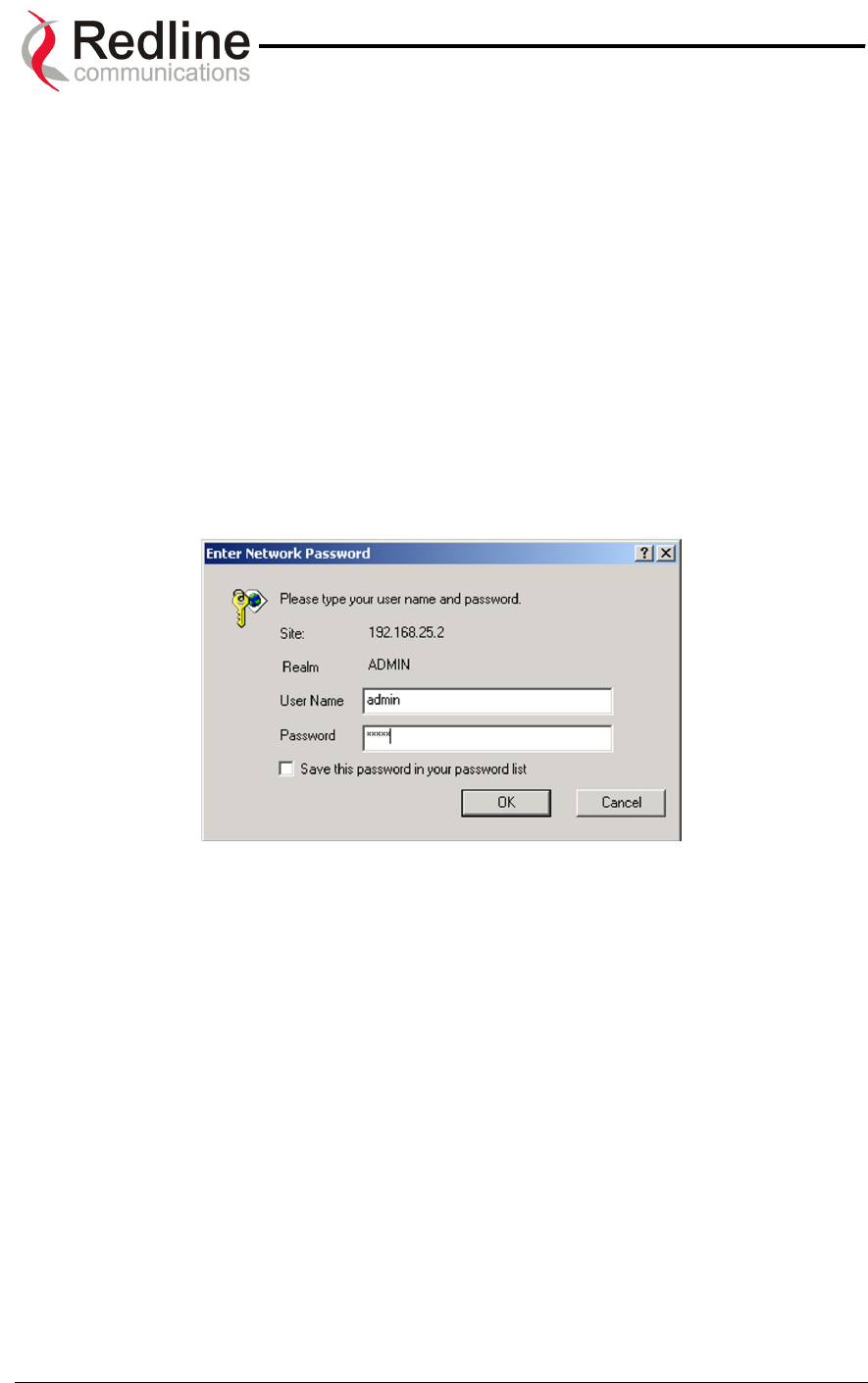
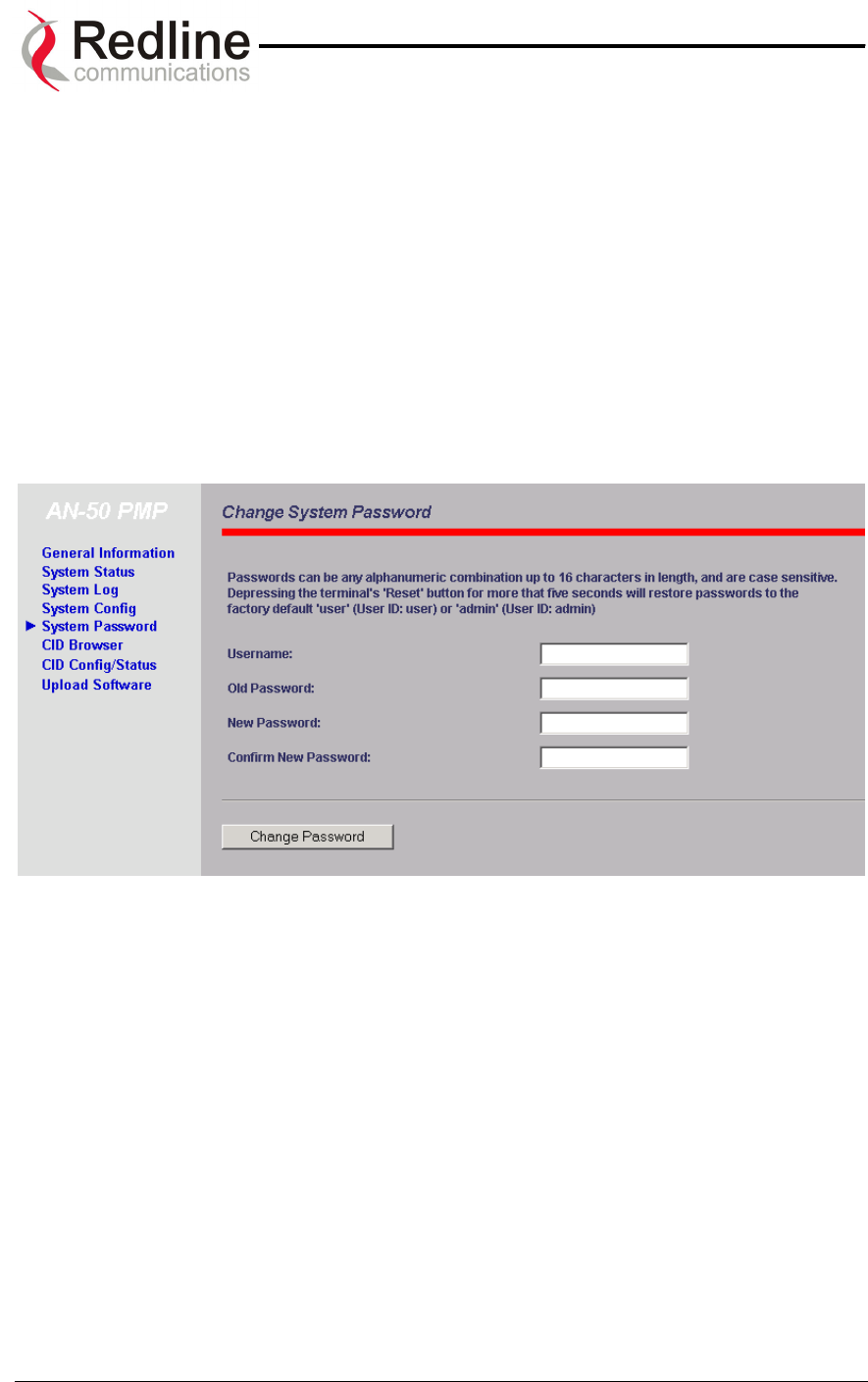
An example of the user name and password screen is shown in Figure 17. The default
value (set at the factory) for both the user name and password for the Administrator is
"admin". This login allows access to all screens. The default value (set at the factory)
for both the user name and password for the User is "user". This login denies access to
the System Config, System Password, CID Config / Status, Upload Software and Reset
Button on System Status screens. Refer to the System Password screen to change the
password for future sessions. If the password is changed, record it in a secure location
for future reference. Note that the user name cannot be changed from "admin".
Figure 17: User Name And Password Dialog
The main menu on the left includes the following links:
• General Information
• System Status
• System Log
• System Config
• System Password
• CID Browser
• CID Config / Status
• Upload Software
The General Information page does not accept input from the user. Data shown on this
page may be modified via the Configuration page.
Page 31 of 84
AN-50 System User Manual
Redline Communications …..solving the first mile challenge.
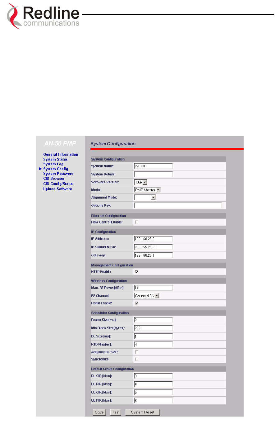
8.1. Configuration
The System Configuration page provides a simple-to-use Graphical User Interface (GUI)
for the operator to input a complete set of system parameters for both the Ethernet and
Wireless components of the AN-50 terminal. Note all parameters under System
Configuration are global and apply to every subscriber station. To store the parameters
into memory, click the Save Configuration button at the bottom of this page. This
operation is recorded in the System Logs.
Note: It is important to ensure that all fields on the System Configuration page are filled out
properly for local and remote terminals. Errors in these fields will result in the inability to establish
a communication link. Please read carefully to ensure a quick, trouble-free deployment.
Figure 18: System Configuration
Page 32 of 84

AN-50 System User Manual
Redline Communications …..solving the first mile challenge.
The system configuration includes the following fields:
System Configuration:
System Name: An alphanumeric identifier for the local terminal, which can consist of
any combination of letters and numbers up to 20 characters in length. The default name
for the system from the factory is set to WEB01. The name remains with the system,
even during power off states, until the operator re-types a new name using this menu
field.
System Details: Specifies the location of the unit, telephone number and/or contact
information of the network administrator. Can be up to 20 characters in length.
Software Version: Specifies the current version of the system software. Note that
software can be remotely downloaded into the AN-50 terminal. The system includes
sufficient memory to hold two independent software loads. The operator can specify
which software load is used in the system. See section 8.6 for additional details.
Mode: Sets the AN-50 to serve as the PMP master, PTP master or PMP / PTP slave.
One and only one unit must be set as the master. A slave will not communicate with
another slave.
Alignment Mode: Specifies the current alignment mode: buzzer or vu-meter (future
release). The buzzer provides an alignment tone sweep generator located in the T-58
Transceiver for fine-tuning based on signal strength. Faster repetitions of the tone sweep
indicate better alignment.
Options Key: The key is personalized to each unit’s MAC address. The 64 QAM
License Key (an optional purchase item) raises the available Uncoded Burst Rate from
the default 36 Mbps to 54 Mbps. Please ensure that the correct MAC address is
provided when requesting a key from your local Redline representative, or register
directly at http://www.redlinecommunications.com/support/register. Enter the key (case
sensitive), ensure it is correct, and click "Send Key".
Ethernet Configuration:
Flow Control Enable: Flow control is a feature that Ethernet devices use to pause
transmission of incoming packets. If a buffer on the Ethernet port is overrun, the port
transmits a special packet (pause frame) that requests remote ports to delay sending
packets for a period of time. For more information, see Appendix 3 – Support For TDM
Using Third Party Units.
IP Configuration:
IP address: This field is used to provide an IP address for the local AN-50 terminal. The
default address from the factory is 192.168.25.2. For the initial setup, the terminal should
not be connected to the Internet, i.e., the host computer should be connected directly to
the terminal Ethernet port, to avoid address conflicts with other devices on a public
network. Once an IP address has been set, the terminal can be connected to the core
network.
Page 33 of 84
AN-50 System User Manual
Redline Communications …..solving the first mile challenge.
IP Subnet Mask: This field is used to set the desired IP subnet mask. The mask value is
set to "255.255.255.0” (Class C subnet).
Default Gateway Address: Specifies the IP address of the default router / gateway on
the local Ethernet segment.
Management Configuration:
HTTP Enable: Specifies whether configuration can be done using the HTTP interface.
Wireless Configuration:
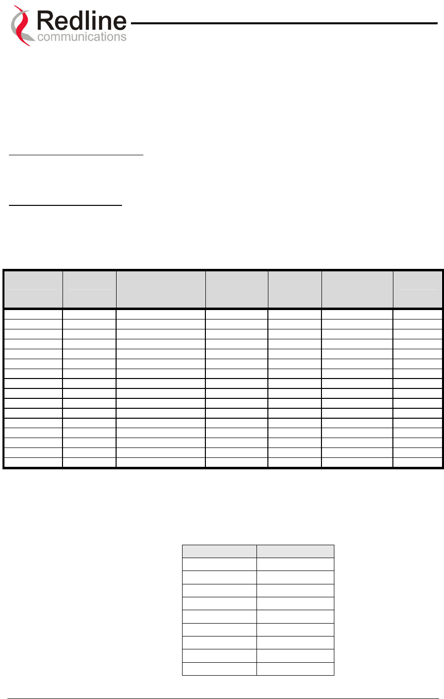
Max RF Power: this parameter specifies the maximum power level of the system.
Depending on the RF channel, FCC regulations and / or local / regional regulation, the
user must follow the table bellow when determinining the actual power to be used.
Antenna
Part Number
Antenna
Gain (dBi)
Antenna Type Application Minimum
Conducted
Power
(dBm)
Max Conducted
Power Ratings
(dBm)
EIRP Limi
(Watts)
10-0007 14 Directional Flat Panel P to MP -20 21 4
10-0006 15 Directional Flat Panel P to MP -20 20 4
10-0004 23 Directional Flat Panel P to MP -20 13 4
10-0003 28 Directional Flat Panel P to MP -20 8 4
10-0058 22.5 Directional Parabolic P to MP -20 13 4
10-0057 29 Directional Parabolic P to MP -20 6 4
10-0059 31.2 Directional Parabolic P to MP -20 4 4
10-0068 29 Directional Parabolic P to MP -20 6 4
10-0069 31 Directional Parabolic P to MP -20 4 4
10-0004 23 Directional Flat Panel P to P -20 26 No Limit
10-0003 28 Directional Flat Panel P to P -20 26 No Limit
10-0058 22.5 Directional Parabolic P to P -20 26 No Limit
10-0057 29 Directional Parabolic P to P -20 26 No Limit
10-0059 31.2 Directional Parabolic P to P -20 26 No Limit
10-0068 29 Directional Parabolic P to P -20 26 No Limit
10-0069 31 Directional Parabolic P to P -20 26 No Limit
RF Channel: specifies the operating channel of the system, within the 100 MHz
available in the 5.8 GHz UNII band. The table below specifies the center frequencies of
each permitted channel.
Channel Frequency
1 5735 MHz
1A 5745 MHz
2 5755 MHz
2A 5765 MHz
3 5775 MHz
3A 5785 MHz
4 5795 MHz
4A 5805 MHz
5 5815 MHz
Page 34 of 84

AN-50 System User Manual
Redline Communications …..solving the first mile challenge.
To avoid interference, two PMP / PTP links operating in the same physical location (co-
located) or within close proximity must be separated by at least one channel, i.e., the
gap between channels must be 20 MHz or more (e.g., channels 2 and 3).
Radio Enable: Specifies whether radio transmission is enabled.
Scheduler Configuration:
Frame Size: Specifies the maximum round trip time interval between the master and the
slave station. This value can be set between 1 ms up to 8ms.
Min Block Size: Specifies the minimum transmitted block size over the air. By varying
the block size the user can trade off data efficiency (ie the ratio of payload bytes data to
overhead bytes) for decreased delay.A larger block size improves efficiency but
increases delay. Typically smaller block sizes are better suited to, real-time applications
such as voice services, while the larger block sizes offer higher throughputs levels to
non-real-time applications like music downloads, web browsing or FTP transfers
DL Size: Specifies the Downlink (DL) sub-frame size.
RTD Max: Specifies the maximum round trip delay (RTD) allowed.
Adaptive DL Size: Checking this box sets the system to operate in adaptive modulation
mode. It is recommended to keep the AN-50 in this mode so that the system can
automatically change the modulation scheme to the highest possible order, based on
measured RF performance. The user can define the desired modulation scheme by
setting the maximum RF Power parameter. If the current RF Power meets or exceeds
this rate, the Wireless Signal LED on the front panel lights solid green. If packet errors
exceed one in one million, the system will automatically step down the modulation
scheme to maintain the link. The Wireless Signal LED will flash green if the current RF
Power is lower than the configured RF Power. If errors continue when the system
reaches the lowest order modulation scheme, the Signal and Link LEDs will turn off to
indicate a failed RF link.
The user can also disable the dynamic modulation mode by un-checking the Adaptive
DL Size checkbox. In this manual mode, the user is required to set the RF Power. It is
recommended the system not operate in manual mode. If it is necessary to operate in
manual mode, first sample the link with Adaptive DL Size enabled, then switch to manual
mode and use a lower order modulation scheme.
Synchronize: Checking this box will use the external synchronization BNC connectors
to synchronize multiple sectors. The units that are synchronized must be set to use the
same frame size and length.
Default Group Configuration:
DL CIR: Specifies the committed information rate (CIR) broadcast for the downlink (DL)
stream.
Page 35 of 84

AN-50 System User Manual
Redline Communications …..solving the first mile challenge.
DL PIR: Specifies the peak information rate (PIR) broadcast for the downlink (DL)
stream.
UL CIR: Specifies the committed information rate (CIR) broadcast for the uplink (UL)
stream.
UL PIR: Specifies the peak information rate (CIR) broadcast for the uplink (UL) stream.
System Configuration Buttons:
Save: Saves the currently entered parameters. Note that clicking Save Configuration will
also initiate a "short reset" - a useful feature when a reset is required on a remote
terminal.
Test: Allows testing of the current settings for five minutes, after which the system
reverts to the previously saved settings. To make settings permanent, click 'Save’.
System Reset: Resets all statistics and reboots the terminal.
* Note: In some countries outside of North America, the Max. Operational Power Per Channel with a given
antenna is limited in accordance to maximum allowable EIRP levels for the region.
8.2. CID Configuration and Status
The CID Configuration and Status page provides a simple to use Graphical User
Interface (GUI) for the operator to configure all channel parameters. To store the
parameters into memory, click the Save CIDs in Flash button at the bottom of this page.
This operation is recorded in the System Logs.
Note: It is important to ensure that all fields on the CID Configuration page are filled out
properly for local and remote terminals. Errors in these fields will result in the inability to
establish a communication link. Please read this section carefully to ensure a quick,
trouble-free deployment.
Figure 19: CID Config / Status
Page 36 of 84

AN-50 System User Manual
Redline Communications …..solving the first mile challenge.
CID Properties:
ID: Select the channel ID (CID) to be configured, deleted or displayed for the system in
which you are interested. In order to locate the proper CID number use the CID Browser
described in section 8.3.
CID Screen Buttons:
Configure: Calls the Link Configuration screen (see section 8.2.1) for the selected CID.
Delete: Deletes the selected CID.
Status: Displays the Link / Connection Status screen (see section 8.2.2) for the selected
CID.
New CID: Adds a new CID by calling the Link Configuration screen (see section 8.2.1).
Save CIDs in Flash: Saves the entire CID table in Flash.
Clear all CIDs: Clears all CIDs from the volatile memory.
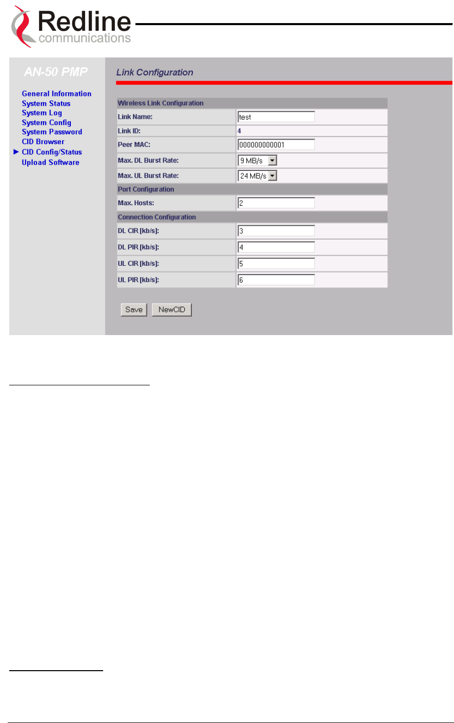
8.2.1. Link Configuration
This screen is displayed through the CID Config / Status screen by clicking the Config
button. Please note that this screen will be active only on the AN-50 operating in PMP /
PTP master mode. The fields in the Link Configuration screen need to be filled out for
each individual subscriber station.
Page 37 of 84
AN-50 System User Manual
Redline Communications …..solving the first mile challenge.
Figure 20: Link Configuration
Wireless Link Configuration:
Link Name: A user specified alphanumeric identifier for the link. The name remains with
the system, even during power-off states, until the operator re-types a new name using
this menu field.
Link ID: Automatically generates a numeric CID for the specified link name. For a new
link, the default ID is always zero. After saving the parameter on the Link Configuration
screen, the AN-50 system will automatically choose a link ID other than zero. Using the
CID Browser, one can search for the specific Link ID (CID) associated with the link
name.
Peer MAC: Enter the MAC address of the remote terminal to register the remote unit.
Note that if the MAC address is not properly entered on both sides, no Ethernet packets
can be transferred.
Max. DL Burst Rate: Maximum downlink (DL) burst rate. Note: Defines the maximum
downstream burst rate associated with the adaptive modulation scheme.
Max UL Burst Rate: Maximum uplink (UL) burst rate. Note: Defines the maximum
upstream burst rate associated with the adaptive modulation scheme.
Port Configuration:
Max Host: Defines the maximum number of hosts (i.e. PCs, …etc) to be learned from
the corresponding CID. Note each AN-50 system uses one CID.
Page 38 of 84
AN-50 System User Manual
Redline Communications …..solving the first mile challenge.
Connection Configuration:
DL CIR: Enter the downlink Committed Information Rate (CIR)
DL PIR: Enter the downlink Peak Information Rate (PIR)
UL CIR: Enter the uplink Committed Information Rate (CIR)
UL PIR: Enter the uplink Peak Information Rate (PIR)
Link Configuration CID:
Save: Saves changes to the current link ID configuration.
New CID: Save current link ID configuration under a new Link Name.
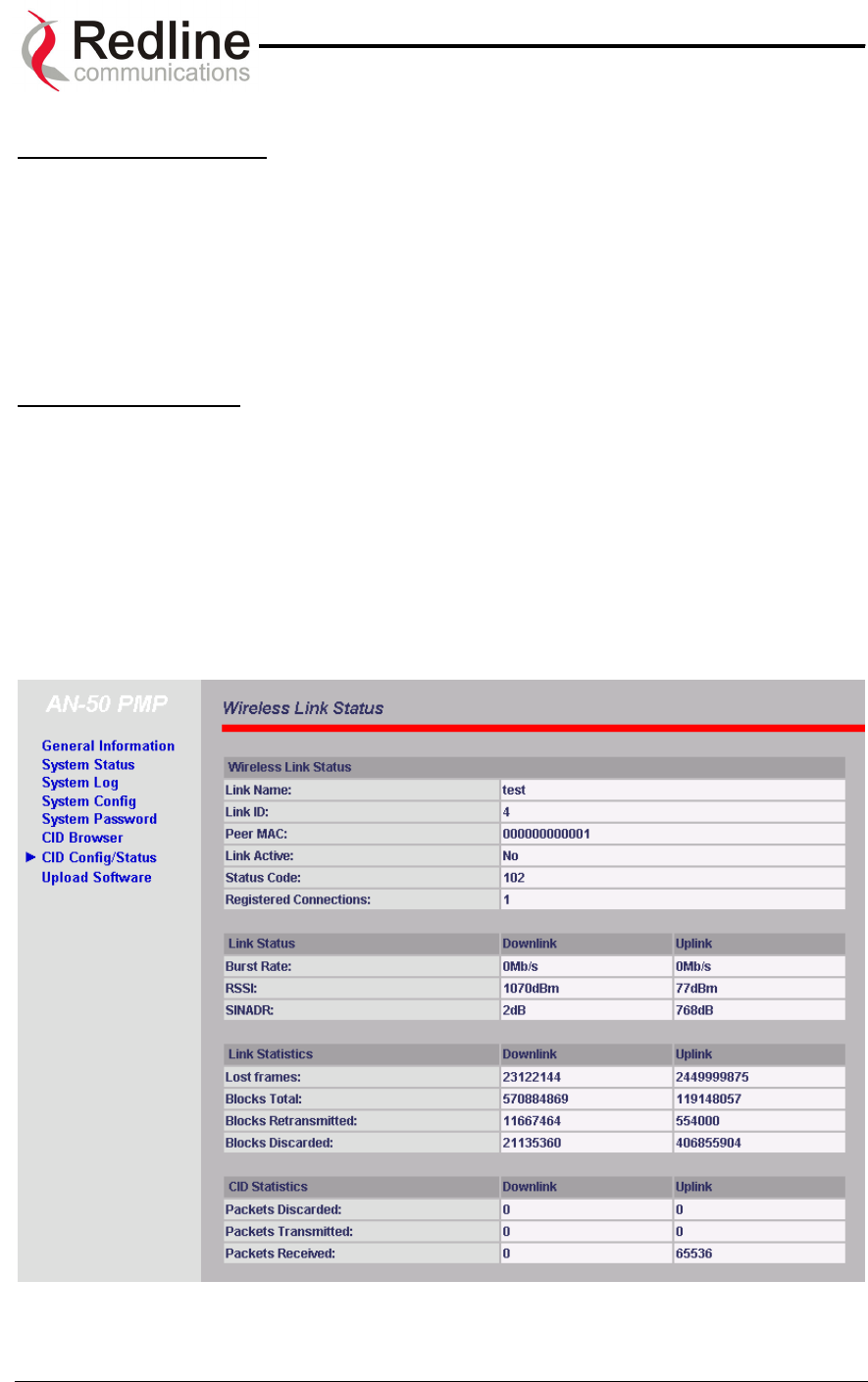
8.2.2. Wireless Link Status
This screen is displayed through the CID Config / Status screen by pressing the Status
button.
Figure 21: Wireless Link Status
Page 39 of 84

AN-50 System User Manual
Redline Communications …..solving the first mile challenge.
Wireless link Status:
Link Name: Displays the link name from the system memory. The name remains with
the system even during power off states, until the operator re-types a new name using
this menu field.
Link ID: Displays the link ID automatically defined by the AN-50 System for the link
name.
Peer MAC: Shows the MAC address of the peer station
Link Active: "Yes" indicates the RF link with the remote terminal is established. "No"
indicates there is no RF link to the remote terminal. This indicator is correlated to the
Wireless Link LED of the slave AN-50.
Status Code: A code shown as a hex number indicating the condition of the RF
components within the AN-50 terminal and T-58 Transceiver.
Registered Connections: Shows the total number of connections configured for this
link. For AN-50 operating in PTP mode the system will always display one (1)
connection.
Link Status Downlink / Uplink:
Burst Rate [Mb/s]: Indicates the current master Tx burst rate. With adaptive modulation,
this rate may change over time, depending on the prevailing propagation conditions.
RSSI [dBm]: Indicates the average received signal strength (RSSI) at the slave remote
site.
SINADR [dB]: Indicates the average signal to interference noise and distortion ratio
(SINADR) at slave remote site. The ratio is based on the digital information provided
from the output of the A/D converter and includes the effects of the AGC.
Link Statistics Downlink / Uplink:
Lost Frames: Shows the total frames lost from master to slave
Blocks Total: Shows the total blocks transmitted between master and slave
Blocks Retransmitted: Shows the total blocks retransmitted between master and slave
Blocks Discarded: Shows the total blocks lost between master and slave
CID Statistics Downlink / Uplink:
Packets Discarded: Indicates the total number of packets discarded due a full buffer full
Packets Transmitted: Indicates the total number of packets transmitted by the master
unit
Page 40 of 84
AN-50 System User Manual
Redline Communications …..solving the first mile challenge.
Packets Received: Indicates the total number of packets received by the slave unit
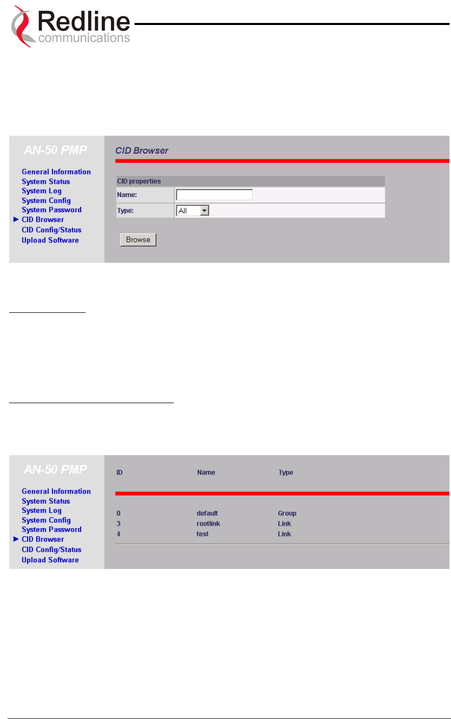
8.3. CID Browser
Figure 22: CID Browser
CID Properties:
Name: Name of remote unit being searched. Note partial string pattern or entire link
name can be input.
Type: Defines search criteria based on entity type: Link, Connection or All
CID Browser Button and Results:
Browse: Displays the CID Brower results as a list of CIDs, one per line as shown
bellow:
Figure 23: CID Browser Results
ID: List the channel ID associated with each link
Name: List the name associated with each ID
Type: List the type of the link, e.g. Group or link.
Page 41 of 84
AN-50 System User Manual
Redline Communications …..solving the first mile challenge.
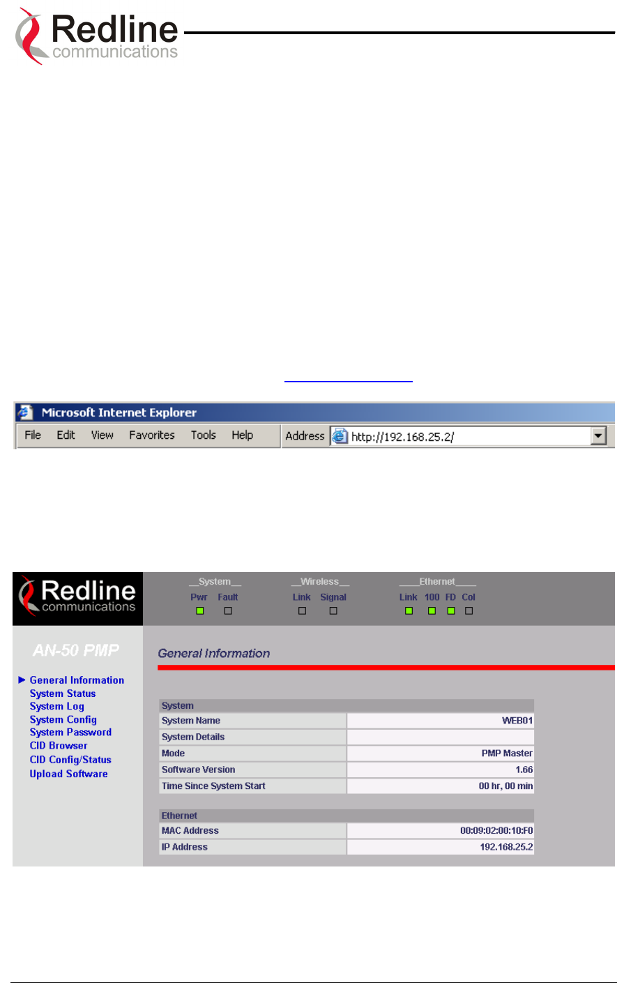
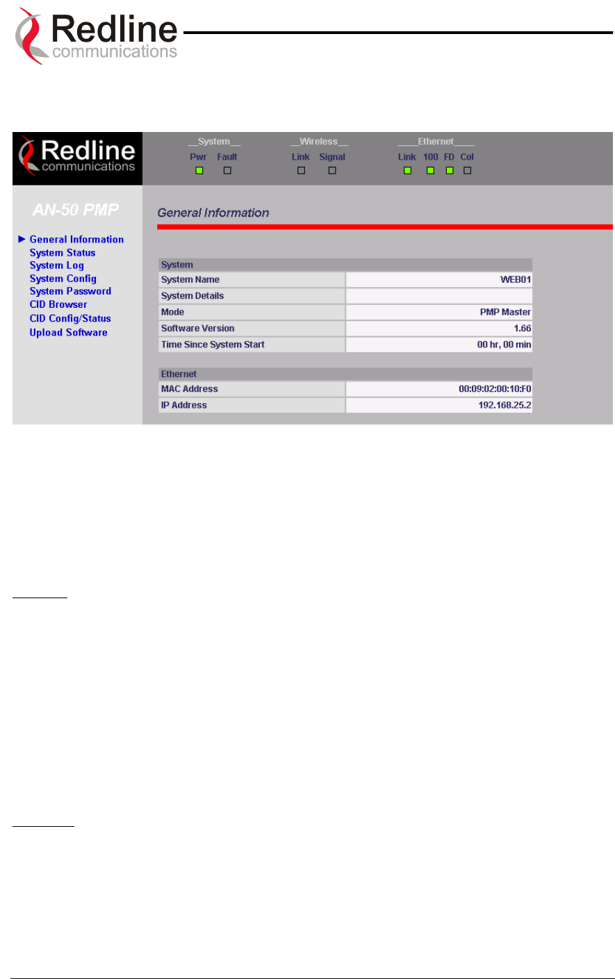
8.4. General Information
Figure 24: AN-50 General Information
Located at the top of this page is a graphic interface providing a real-time synoptic view
of the AN-50 terminal front panel (refreshed every 30 sec.), plus a summary of general
information related to the configuration and status of the local unit.
The following is a brief description of each field on the General Information page:
System:
System Name: Identifies the local terminal. The factory default name for the system is
“WEB01”.
System Details: Specifies the location, telephone number and/or contact information.
Master Mode: Specifies whether the AN-50 operates in PMP / PTP master or slave.
Software Version: Specifies the software version in use.
Time Since System Start: Specifies the time [dd/hh/mm/ss] since the system started.
Ethernet:
Ethernet MAC Address: Specifies the Ethernet MAC address used by the local
terminal.
IP Address: Specifies the IP address used by the local terminal.
Page 42 of 84
AN-50 System User Manual
Redline Communications …..solving the first mile challenge.
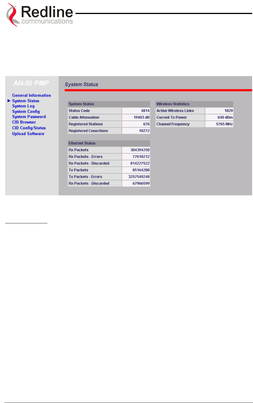
8.5. System Status
Clicking on System Status in the main menu will load this page, which provides General
Information, Ethernet LAN Statistics and Wireless Statistics of the unit of interest, as
shown in Figure 25.
Figure 25: System Status
System Status:
RF Status [Error Code]: An error code indicating the condition of the RF components
within the AN-50 terminal and T-58 Transceiver. See error list below for details:
AN-50 PLL Error: The PLL (Phase Locked Loop) section within the AN-50 terminal
experienced an error. The System Fault LED may light. Try resetting the unit.
Communication Error Over IF Cable: Communication between the AN-50
terminal and the T-58 Transceiver failed. Check the IF cable and connectors.
Radio High Temp. Warning: The T-58 Transceiver’s internal temperature rose
above 185F / 85C. The transceiver will shut down for 30 seconds to allow cooling
time.
Radio Power Supply Fault: Indicates a fault in the transceiver’s power supply. This
error could be due to a problem with the internal power supply, or with the power
source from the AN-50 terminal. If the Low DC Voltage At Radio error is also
indicated, (see below) check the IF cable and connectors. If the Low DC Voltage At
Radio error is not indicated, the T-58 Transceiver will require servicing.
Low DC Voltage At Radio Input: The DC voltage at the transceiver (carried by the
IF cable from the AN-50 terminal) is lower than the required 24VDC. Check the IF
cable and connectors. The minimum required voltage for operation is 12VDC.
Cable Attenuation: Indicates the attenuation of the signal over the IF cable.
Registered Station: Shows the total number of configured links. If the AN-50 operates
in PTP mode this field will display one.
Page 43 of 84

AN-50 System User Manual
Redline Communications …..solving the first mile challenge.
Registered Connection: Shows the total number of configured connections. If the AN-
50 operates in PTP mode this field will display one.
Ethernet Status:
Rx Packets: Indicates the total number of received packets.
RX Packets – Errors: Indicates the total number of packets received with errors
Rx Packets - Discarded: Indicates the total number of packets discarded due to full buffer.
Tx Packets: Indicates the total number of all transmitted packets
Tx Packets – Errors: Indicates the total number of packets transmitted with error
Tx Packets – Discarded: Indicates the total number of packets discarded due to full buffer
Wireless Statistics:
Active Wireless Links: Shows the total number of active links
Current Tx Power: Specifies the actual current transmit power level
RF Channel Frequency: Specifies the center frequency of the channel in use
Page 44 of 84

AN-50 System User Manual
Redline Communications …..solving the first mile challenge.
8.6. Upload Software
We need an introduction, and an explanation of BS and SS.
To move from a PTP to PMP configuration, one end must be designated as the new
Base Station (BS) site, the software must be upgraded, and the antenna must be
changed from the typical 9 or 4.5 degree narrow beam PTP antenna to a 60 or 90
degree sector antenna. Redline offers the necessary upgrade kits in order to accomplish
this.
It should be noted that when migrating a PTP system to PMP, the designated Subscriber
Station (SS) side will see an overall reduction in signal strength due to the BS antenna’s
lower gain. The installer must take this into consideration before upgrading any
installation. Failure to do so could result in performance degradation in terms of
throughput at a given range. It is recommended that customers contact their Redline
Partner to calculate the expected link budget before proceeding with any upgrade.
The upload screen shown below is used to upgrade the existing software load of the AN-
50 terminal with new software stored in a binary file on the server or host computer. Note
the AN-50 terminal contains two memory pages for storing two versions of the
software/firmware. The user can select the operating version using the Configuration
screen Software Version. The upload will always overwrite the secondary (unselected)
version; therefore it is important to select the desired operating version before beginning
the upgrade process.
The upgrade process can be achieved remotely, using the Trivial File Transfer Protocol
(TFTP) over the Internet. The operator must fill in two input fields: TFTP Server IP
Address and File Name. The TFTP Server IP Address is the IP address of the host
computer or server that contains the upgrade software in binary format, while File Name
is the name of the actual binary file.
Figure 26: Upload Software
Page 45 of 84
AN-50 System User Manual
Redline Communications …..solving the first mile challenge.
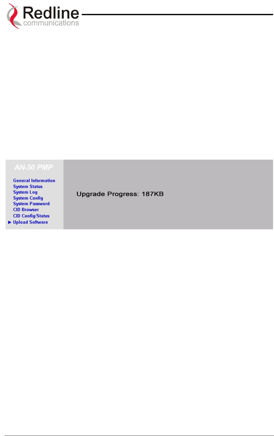
After typing the TFTP Server IP Address and File Name, click Upload File to begin the
file transfer. A status screen (see Figure 27) will appear, displaying the number of bytes
being transferred from the host computer/server to the AN-50 terminal in real time. The
upgrade file size is approximately 1.5 MB, and will take approximately two to four
minutes to download from the server to the AN-50 terminal memory. To activate the
new version, it is necessary to go to the Configuration page and select the new Software
Version.
Upon successful transfer of the file, the terminal will verify the integrity of the new
software. If errors were introduced during the transfer process as a result of (for
example) link degradation, the AN-50 terminal will reject the new software load and
provide a warning that the upgrade was unsuccessful. In this case, the operator will
need to repeat the upload process.
Figure 27: File Transfer Progress
Page 46 of 84
AN-50 System User Manual
Redline Communications …..solving the first mile challenge.
8.7. System Password
The factory default password for the system is "admin" for the administrator’s ID, and
“user” for the user’s ID. To change the password, click on System Password from the
main menu and apply a new value in the New Password field (see Figure 28) using any
alphanumeric combination. Note the field is case sensitive and can be up to 16
characters in length.
For more information on password related issues, see section 8 on page 30.
Note: depressing the front panel Reset button for more that five (5) seconds will restore
the factory default passwords.
Figure 28: System Password
Page 47 of 84
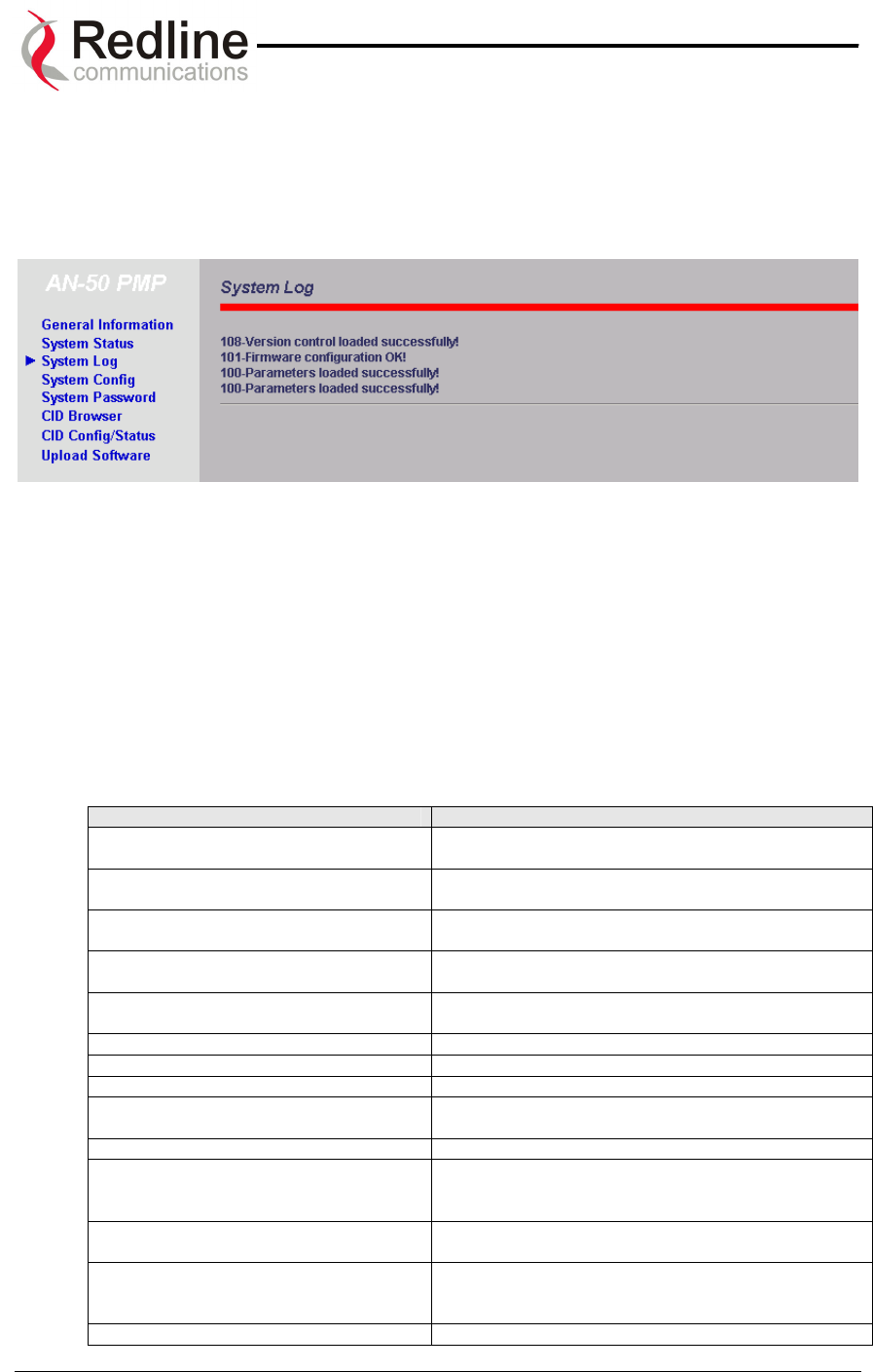
AN-50 System User Manual
Redline Communications …..solving the first mile challenge.
8.8. System Logs
The System Logs page, shown in Figure 29 below, provides a list of the last forty
messages recorded by the AN-50 terminal, describing either system activity or errors
that have occurred.
Figure 29: System Logs Screen
The logs will also indicate if the following transactions were successfully completed:
• Save Configuration – Under the Configuration screen.
• Upload – Under the Upload Software screen.
• Change Password – Under the System Password screen.
• Send Options Key
The following table provides a brief description of the key messages recorded in the logs
by the system:
Log Message Description
100-Parameters loaded successfully! All system parameters have been successfully
downloaded.
101-Firmware configuration OK! The onboard firmware configuration has been
properly set up.
102-Ethernet port configured! The Ethernet port has been properly configured and is
operational.
103-Parameters saved successfully! The latest configuration parameters have been
successfully saved into the system memory.
104-Upgrade OK! The software upgrade process completed
successfully.
105-Password changed successfully! The system password was successfully changed.
106-Firmware programmed OK! The firmware was successfully programmed.
107-Statistics initialized! Reset of statistics was successful.
108-Version control loaded successfully! Software version control data was successfully
loaded.
109-Options Key activated! Product Options Key was accepted.
110-Options Key already used! The Product Options Key was not accepted because
it was already used once. Contact your local Redline
representative.
201-EEPROM corrupted. Def. param.
loaded!
The memory area containing the system configuration
has been corrupted. Default parameters loaded.
202-Error while saving parameters! The latest configuration parameters have not been
successfully saved. In this case, repeat the save
configuration process to try to resolve the problem.
203-Another upgrade in progress! The system is already in upgrade mode, in the event
Page 48 of 84

AN-50 System User Manual
Redline Communications …..solving the first mile challenge.
the operator inadvertently invoked multiple
simultaneous upgrades.
204-Invalid upgrade parameters! The parameter entered is in error. If this message
appears, check for typing errors.
205-Upgrade failed! The software upgrade process completed
unsuccessfully.
206-Password changed unsuccessfully! The new password entered into the system was not
successful. In this case, repeat the process.
207-Timeout on reading data packet! The system has timeout looking for packets from the
host computer or server. Check for obvious problems
such as disconnected or faulty cable.
209-TFTP error received! The Trivial File Transfer Protocol (TFTP) routine used
to download the software to the AN-50 terminal during
the Upgrade process failed. Likely cause is
disconnected or faulty cable.
210-Error: TFTP unknown message! The TFTP client received an unknown message. In
this case, repeat the upgrade process.
211-Error: while writing flash!
While writing the new software into AN-50 terminal
flash memory an unexpected error occurred. Try to
repeat the process and if the error persist contact
your local Redline representative.
212-Error firmware configuration! An unexpected error occurred while writing the
onboard firmware configuration. Try to repeat the
process.
213-Firmware programming failed! The firmware programming failed.
214-Error while loading version control! Software version control data was not loaded
successfully.
215-Log buffer full! The log buffer overflowed.
216-Invalid Options Key! User entered an invalid Product Options key.
217- PLL unlocked! One or more RF synthesizers unlocked. The unit
stopped RF transmissions and attempted to
reprogram the synthesizers. If this message repeats
or if the RF link is not back on, try to reset the
terminal. If the problem persists, contact customer
support.
218-Outdoor unit over temperature! The T-58 Transceiver's internal temperature rose
above 185F / 85C. The transceiver will shut down for
30 seconds to allow cooling.
219-Excessive DC loss on IF cable! The DC voltage at the transceiver (carried by the IF
cable from the AN-50 terminal) is lower than the
required 24VDC. Check the IF cable and connectors.
220-Outdoor unit power supply fault! Indicates a fault in the transceiver's power supply.
This error could be due to a problem with the internal
power supply, or with the power source from the AN-
50 terminal. If the 'Excessive DC loss on IF cable'
error is also indicated, check the IF cable and
connectors. If not, the T-58 Transceiver will require
servicing.
Page 49 of 84
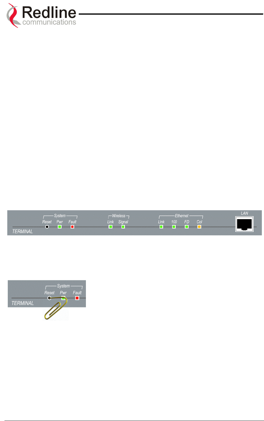
AN-50 System User Manual
Redline Communications …..solving the first mile challenge.
9
9.
.
D
Di
ia
ag
gn
no
os
st
ti
ic
cs
s
a
an
nd
d
T
Tr
ro
ou
ub
bl
le
es
sh
ho
oo
ot
ti
in
ng
g
Troubleshooting can be performed using the front panel LEDs and the host
computer/server connected locally or remotely to the AN-50 terminal.
Before beginning any troubleshooting via the front panel, it is important to ensure that all
fields on the System Configuration page are filled out properly for local and remote
terminals, as outlined in Section 8.1. Errors in these fields will result in the inability to
establish a communication link. Also ensure that all cables are properly connected as
outlined in Section 7.
This section provides basic diagnostic and troubleshooting procedures to help solve
problems that may occur with the AN-50 system. If, after reading this section, you are
unable to get the system operating properly, please contact your local Redline
representative. Include the model name and serial number of the system (located on the
back of the unit) in your communications.
9.1. Diagnostics Via The Front Panel
The front panel of the AN-50 terminal comprises three sets of status LEDs, grouped
under the headings System, Wireless and Ethernet, to help with first level diagnoses of
problems encountered with the unit.
Figure 30: Front Panel Status LEDs
Throughout this section, reference is made to the Reset
button, which is a micro-switch recessed in the front panel
in the System block. Use a small narrow object, such as a
paper clip, to access the button. Depressing the button for
less than five (5) seconds will activate a "short reset",
which is equivalent to turning the AN-50 terminal off and
on. Statistical values are reset, and the currently loaded software / firmware will be
retained. Note that a short reset may be accomplished remotely by clicking on the Save
Configuration button on the System Configuration screen.
Depressing the Reset button for more than five (5) seconds executes a "long reset". A
long reset reloads the factory default configuration settings such as IP Address,
IP Subnet Mask, Channel, System Name, etc. and restarts the system. The software
version that existed in the system before the long reset is retained. An example of when
a long reset will help is in the event that a password or IP address is forgotten. The long
reset function will simply restore the system back to its original factory default settings.
A long reset is confirmed by the Wireless Link LED flashing three times, followed by the
LED power-up sequence:
Page 50 of 84
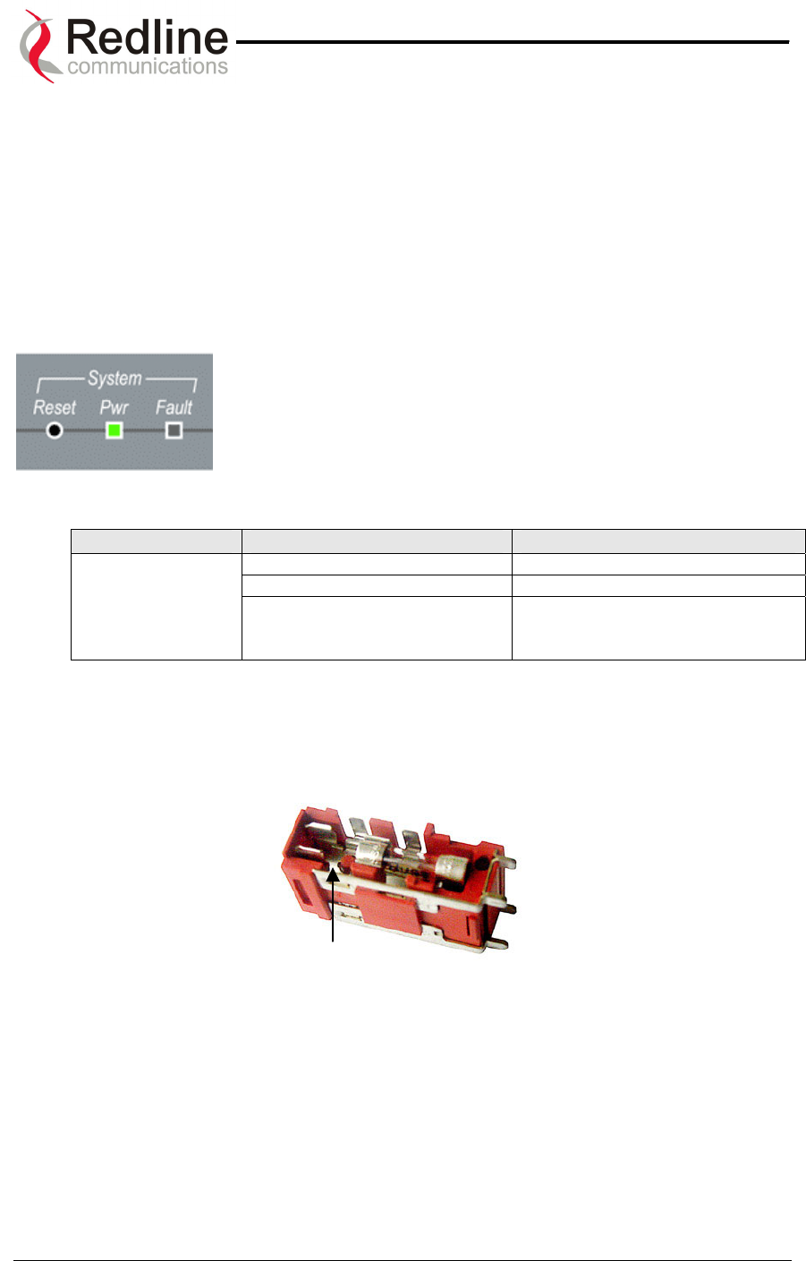
AN-50 System User Manual
Redline Communications …..solving the first mile challenge.
All four Ethernet LEDs light for one second, then individual Ethernet LEDs blink twice in
the following order: 100, FD, Col, Link. The Fault LED lights for approximately four
seconds, then turns off. The two Wireless LEDs remain off for approximately five
seconds, then blink once and resume their normal state.
The remainder of this section lists possible problems that may occur and the
corresponding remedies.
9.1.1. System Power
If the Pwr LED is not illuminated solid green, power is not
getting to the unit. The most probable causes are:
Table 1: System Power Diagnostics
Symptom Possible Problem Solution
On/Off switch in Off position Turn on switch at back of unit.
Fuse blown Replace fuse. (spares provided)
Pwr LED does
not illuminate
Power cord disconnected Securely connect cord to terminal
and outlet.
To replace a fuse, pop the black plastic cover located on the back panel beside the
power switch, and extract the red fuse holder. Be certain to replace the fuse(s) into the
lower half of the holder, as shown in the diagram below. The fuse holder holds two
fuses, both of which are active. Be certain to use fuses of the same type and rating.
Note space
Page 51 of 84
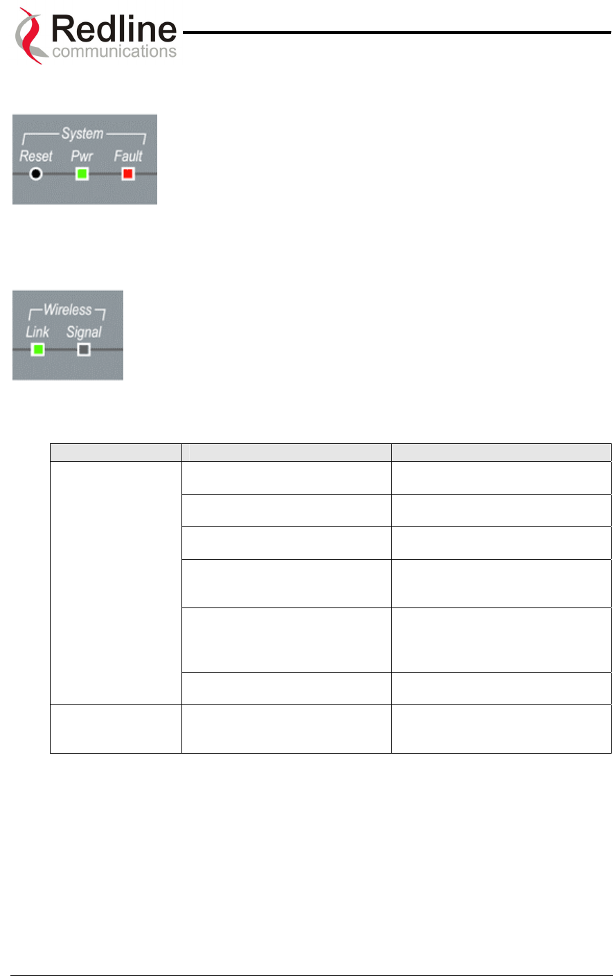
AN-50 System User Manual
Redline Communications …..solving the first mile challenge.
9.1.2. System Fault
If the Fault LED illuminates solid red, it is an indication that there
is a serious problem with the system software or hardware.
Check the IF cable. A short or long reset may fix the problem. If
not, contact your local Redline representative. Also refer to the
RF Status codes , as well as the System Logs.
9.1.3. Wireless Link
The Wireless Link LED illuminates solid green when the wireless link
is established to the remote terminal. When the Link LED is off, it is an
indication there is a problem with either the terminal link, radio, or with
the actual propagation path itself. Check the RF Status parameters in
the System Status screen. The table below lists some of the potential
causes:
Table 2: Wireless Link Diagnostics
Symptom Possible Problem Solution
Remote terminal is not on or is
malfunctioning.
Verify operation of remote
terminal.
The propagation path is
blocked.
Clear path or re-locate antennas.
The transceiver is mal-
functioning.
Repair or replace transceiver
Antenna has moved and is no
longer aligned with remote
terminal.
Re-align the antenna.
Cable between transceiver and
antenna or between transceiver
and terminal not properly
connected.
Properly secure cables.
No wireless link
(Link LED does
not illuminate)
Power not getting to the
transceiver from the terminal.
Repair or replace terminal.
Receiver and transmitter have
been set to different RF
channels.
Make sure both units are
operating on the same RF
channel.
Page 52 of 84
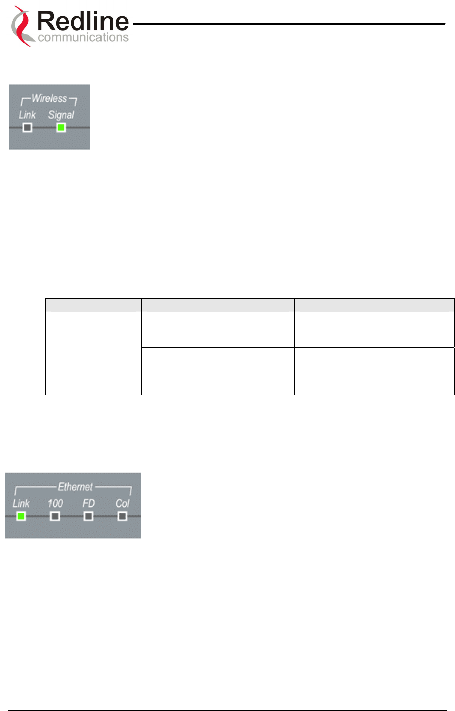
AN-50 System User Manual
Redline Communications …..solving the first mile challenge.
9.1.4. Wireless Signal
When Adaptive Modulation is enabled, the Wireless Signal LED will
light solid green if the system is operating at or above the configured
Uncoded Burst Rate, and will flash when the system is operating at a
lower order modulation scheme (i.e., the current Uncoded Burst Rate
is lower than the configured Uncoded Burst Rate). If the system
cannot maintain the lowest modulation scheme due to link errors, the
Signal LED will turn off.
When Adaptive Modulation is disabled, the Wireless Signal LED will light solid green if
the system is operating at an error rate of less than one out of one million packets. If
errors exceed one in one million, the LED will flash. If the wireless link becomes poor,
the LED will turn off.
Flashing may not be a serious problem if the LED flashes only intermittently, however, if
it flashes constantly, the table below summarizes some possible causes:
Table 3: Wireless Signal Diagnostics
Symptom Possible Problem Solution
Obstructions in the propagation
path causing signal
degradation.
Try to remove obstacles or re-
locate antenna.
Antenna moved, due to high
winds.
Re-align the antenna.
Weak RF Link
(Signal LED
flashes)
Poor cable connection between
transceiver and antenna.
Repair or replace the RF cable.
9.1.5. Ethernet Link
The Ethernet Link LED will light solid green when the LAN
connection to the host computer/server or switch/router is
functioning properly. The Link LED flashes when the LAN
connection to the host computer/server or switch/router is
functioning properly and there is traffic. If the LED is off,
look for the following problems:
Page 53 of 84
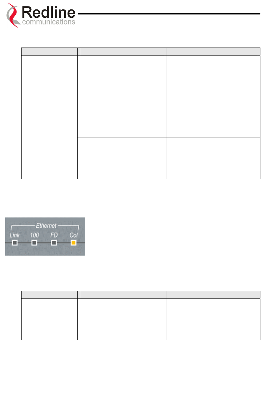
AN-50 System User Manual
Redline Communications …..solving the first mile challenge.
Table 4: Ethernet Link Diagnostics
Symptom Possible Problem Solution
Poor cable connection between
terminal and computer/server
or between terminal and
switch/router.
Carefully check all cable
connections.
Wrong type of Ethernet cable
between terminal LAN port and
host computer/server or
switch/router.
If the terminal LAN port is
connected to a host computer or
server directly, then ensure a
straight-through cable is used.
Otherwise, to connect the
terminal to a switch or router,
ensure a crossover cable is
used.
The auxiliary Network
equipment including
switch/router, host
computer/server, may be
malfunctioning.
Repair or replace faulty units.
No Ethernet Link
(Link LED off)
Processor malfunction. Try short reset or long reset.
9.1.6. Ethernet Collision
The Ethernet Col LED flashes amber when packet
collisions occur over the LAN. Note that when connected to
a hub, it is typical for packet collisions to occur
intermittently. However, if the LED flashes constantly, or
flashes when the AN-50 terminal is connected to a switch
or router, there is a serious problem with the LAN
connection. Some possible causes include:
Table 5: Ethernet Collision Diagnostics
Symptom Possible Problem Solution
Poor cable connection between
terminal and computer/server
or between terminal and
switch/router.
Carefully check all cable
connections.
Link Collision
(Col LED
flashes)
Incompatible Ethernet port
speed.
Confirm speed and duplex mode
of devices.
Page 54 of 84

AN-50 System User Manual
Redline Communications …..solving the first mile challenge.
9.2. Troubleshooting The Web Interface
The section assumes that the status LEDs on the front panel of the AN-50 terminal
indicate normal functionality.
If, after using HTTP commands to try to log onto the AN-50 terminal the General
Information page does not appear on-screen, several possibilities exist. The first test is
to ping the terminal from the host computer by entering the following text from the
command line:
>Ping 192.168.25.2
Note the IP address used in this example is the default address supplied by the factory.
If the IP address has been changed, it is important to use the current address. The
system will always respond to ping frames less that 577 bytes in length.
If the ping test is successful (i.e., the computer was able to send and receive packets
to/from the terminal) then the problem may be with the IP address that was entered or
with the HTTP server itself. Retype the address or re-boot the host computer to try to
resolve the problem.
If the ping is unsuccessful, there may be problems with the IP address that you are
using. Try retyping the address. If this fails, and it appears you have forgotten the IP
address of the terminal, perform a long reset to restore the terminal to the default value.
Warning: performing a long reset will restore the AN-50 terminal’s IP address
(192.168.25.2) and IP Subnet Mask (255.255.255.0) to the factory default value.
Table 6: Web Interface Diagnostics
Symptom Possible Problem Solution
Incorrect IP address and/or
Subnet Mask.
Perform a ping test from the
host computer command line.
If the ping test is unsuccessful,
then the problem is with the IP
address. Perform a long reset to
apply the default address
(192.168.25.2) and Subnet Mask
(255.255.255.0)
Problems with host computer,
or AN-50 terminal.
If the ping is successful try a
short reset of the AN-50, and/or
reboot the host computer.
Home page
(General
Information)
cannot be
accessed.
Host PC ARP table is
incorrectly configured
Run “arp –d” whenever the AN-
50 terminal is swapped. Check
that the host PC’s Subnet Mask
matches that of the AN-50
terminal. Check that the host
PC’s address is 192.168.25.n,
where ‘n’ is not equal to 0, 2, or
255.
Page 55 of 84

AN-50 System User Manual
Redline Communications …..solving the first mile challenge.
9.3. Broadband Fixed Wireless Primer
This section provides an overview of the design and benefits of a Broadband Fixed
Wireless (BFW) network architecture based on the Redline AN-50 system.
There are several advantages of a BFW system over traditional wireline alternatives
such as PSTN, ISDN, T1, DSL, cable and fiber, including:
• Greater availability
• Lower cost of ownership per link
• Higher throughput (with the exception of fiber)
• Greater distances
• Quicker time to market
• Greater portability
The AN-50 system functions logically as a transparent bridge, providing all the benefits
of a converged IP network, i.e., "IP everywhere". A converged network allows operators
to reduce network buildout costs significantly by employing standard IP appliances
everywhere, from backbone to end-user.
Page 56 of 84

AN-50 System User Manual
Redline Communications …..solving the first mile challenge.
9.4. Deployment Scenarios
This section provides a general overview of typical AN-50 Point to Multi-Point (PMP)
deployment scenarios.
The AN-50 base station PMP system supports both 60 and 90 degree cell sectorization,
as illustrated below.
Figure 31: Cell Sectorization
The advantage of the narrower 60 degree beam antenna is that it achieves higher
subscriber density per cell through frequency reuse, higher gain (at greater distances)
and provides greater flexibility in dealing with external interference, again through proper
reuse of the channels. In terms of capacity, the 60 degree pattern can provide a
threefold increase in bandwidth over an omni pattern, while the 90 degree sectorization
scheme can double the bandwidth. This is achieved by reusing the bandwidth – for
example, assume there are two channels, A and B. The 60 degree scheme can support
a sector-to-sector scheme of AB-AB-AB while the 90 degree can support AB-AB. In
terms of interference, a narrower sector provides finer granularity in isolating and re-
allocating channels to avoid the problem, whereas a larger sector has less flexibility.
The key advantage of the 90 degree sector antenna is that fewer systems are required
at the base station to provide full omni coverage. This is an important consideration
when trying to limit the initial capital expenditure necessary to create and grow the
network.
Another means of gracefully growing the network, using narrower sectors, is to begin
with a single sector, and then, as the customer base grows in other directions, to add
sectors until full coverage is achieved. This is shown below, starting with one sector, to
three and then to the full 6 sectors in final deployment.
Page 57 of 84
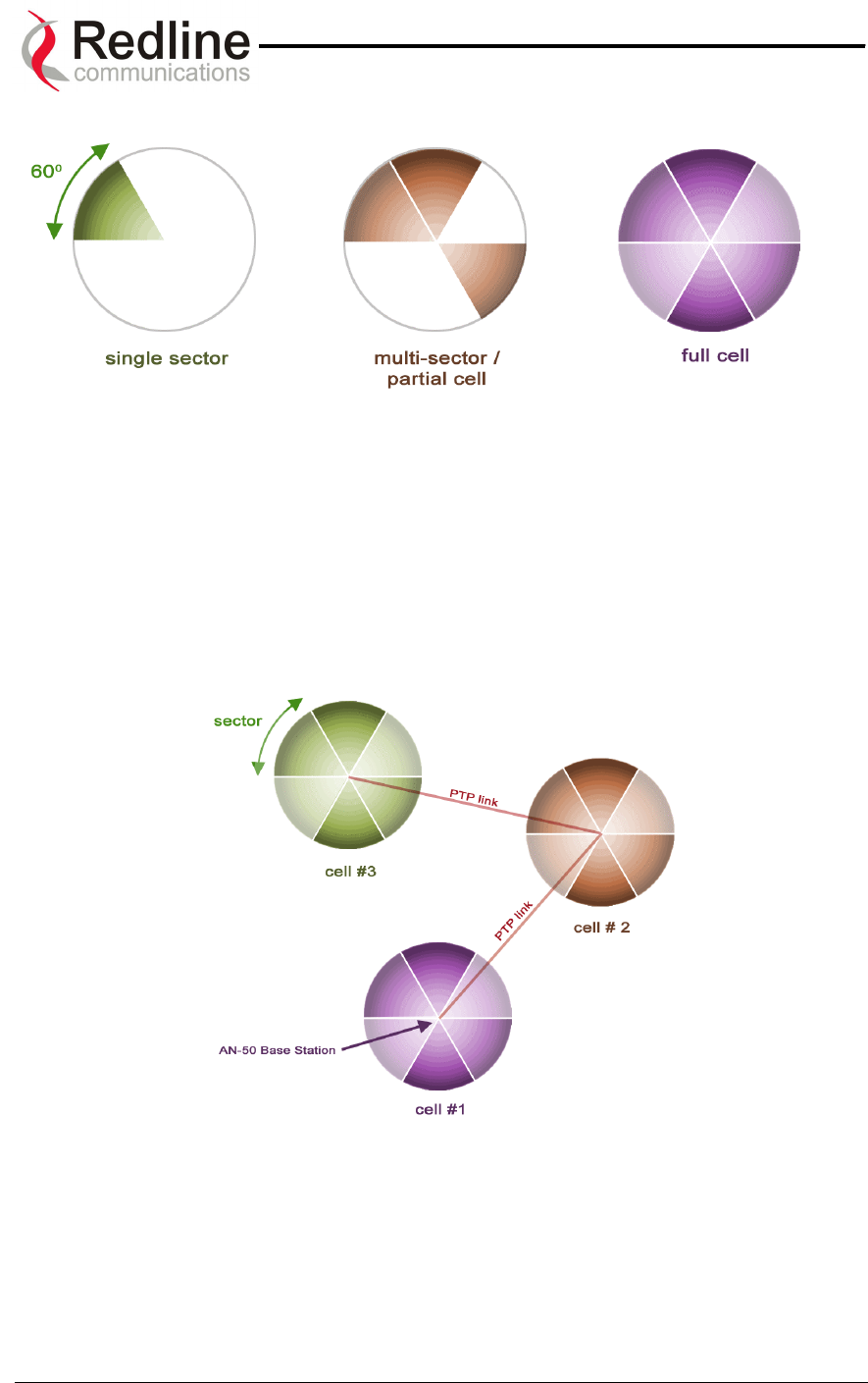
AN-50 System User Manual
Redline Communications …..solving the first mile challenge.
Figure 32: Growing a Network
Note that in some deployment situations involving high tower installations, it may be
prudent to install all six antennas and radios initially, and begin with only a single AN-50
system operating out of one of the sectors.Later, as the customer base grows, the other
sectors can be easily put online by the addition of only the indoor terminals.
Illustrated below is a sample hybrid PTP/PMP sectorized multi-cell deployment
constructed using 60 degree antennas.
Figure 33: Hybrid PTP/PMP
In multi-sector or multi-cell deployments, proper frequency planning is essential in order
to avoid the possibility of co-channel interference. The operator is encouraged to
consider the use of standard cell planning software tools, available from multiple
vendors, for this purpose.
Page 58 of 84
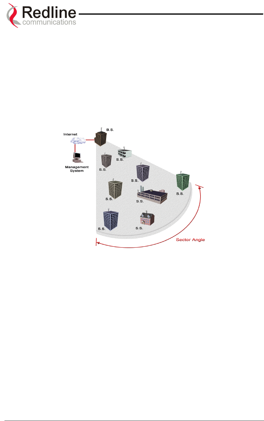
AN-50 System User Manual
Redline Communications …..solving the first mile challenge.
9.5. Who Can Benefit From The AN-50 System?
This section describes various applications addressed by the AN-50 system. All
applications are applicable to both PTP and PMP deployments. Although PMP offers
significant cost saving benefits over PTP deployments, this must be balanced against
throughput and range trade-offs associated with PMP. The figure below illustrates a
typical single sector PMP deployment. As shown, a single BS can service multiple
subscriber stations within its antenna coverage area.
Figure 34: Single Sector PMP Deployment
QoS is guaranteed, in terms of CIR and PIR, at each SS as described previously in this
manual.
The AN-50 system is an ideal solution for:
• Carriers
• Internet Service Providers (ISPs)
• Enterprises
• Educational Institutions and Campuses
A) Carriers
The AN-50 system will provide benefits to both Incumbent and Competitive Local
Exchange Carriers (ILECs and CLECs, respectively). Although ILECs own and provide
services over wireline infrastructures within a specific geographical area, they are faced
with the challenges of reaching outlying regions suffering from poor to no service. The
ILEC is usually compelled to provide an expensive solution using a series of PTP radio
Page 59 of 84
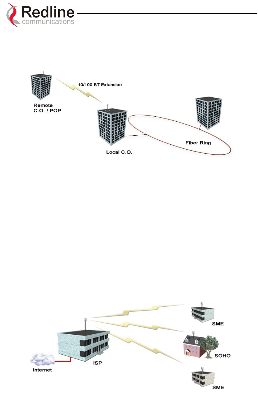
AN-50 System User Manual
Redline Communications …..solving the first mile challenge.
links, with low throughput (e.g., T1) and costly license fees and network interfaces
including T1 multiplexers. The AN-50 system provides a cost-effective alternative, by
connecting a remote site from the local CO, as shown in see Figure 35. Additional
remote sites can be deployed using the PMP variant.
Figure 35: Wireless Extension for Carriers
The same challenges are faced by CLECs, who can use the AN-50 system to:
• Extend their existing fiber network, and
• Establish a remote Point of Presence (POP).
B) Internet Service Providers
The AN-50 system is perfect for ISPs looking to provide cost-effective broadband
solutions to demanding business customers including Small Office Home Office (SOHO)
and Small to Medium sized Enterprises (SME) located just outside of the downtown
core, where there is a lack of infrastructure. As well, the AN-50 is well suited for
MTU/MBUs and backhaul for Hotspots/Internet Cafés. High-speed leased lines are
expensive and hard to obtain, especially from local telephone companies. Wireless
access provides a reliable quality of service over longer distances, while avoiding Telco
access fees.
Figure 36: Wireless Solution For ISPs
Page 60 of 84
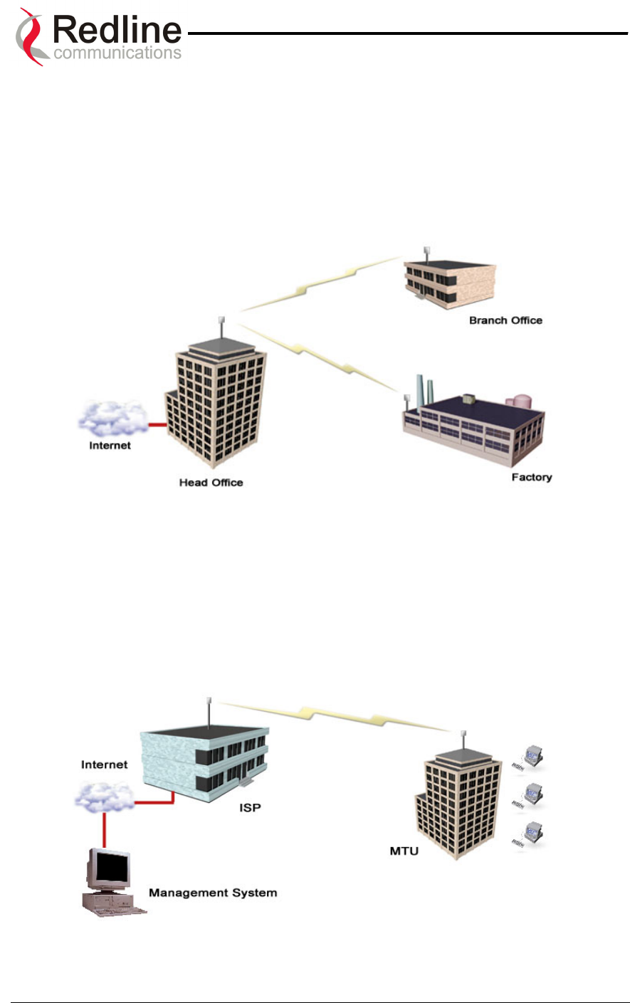
AN-50 System User Manual
Redline Communications …..solving the first mile challenge.
C) Enterprises
Enterprises are particularly frustrated by the lack of broadband connectivity to branch
offices, factories, or warehouses located just outside of the urban core. Establishing a
LAN solution over several remote locations presents a significant inter-network
challenge using conventional wireline solutions. The AN-50 system is well suited for
addressing LAN extension requirements, offering superior data rates in a secure format
using encryption to protect sensitive information.
Figure 37: Wireless Solution For Enterprise
D) Educational Institutions and Campuses
The World Wide Web is a key element within the education system today, with BFW
systems serving as an important enabler in bringing Internet content to the student body.
Fixed wireless systems such as the AN-50 provide a cost effective means of creating a
backbone for connecting existing and new campus buildings to the educational
infrastructure to support distance learning and two-way interactive training.
Figure 38: Wireless Solution for MTUs
Page 61 of 84

AN-50 System User Manual
Redline Communications …..solving the first mile challenge.
9.6. The AN-50 Advantage
The Redline AN-50 system includes several key features to mitigate the effects of
interference arising from other systems operating co-channel in the vicinity, as well as
coping with propagation anomalies such as multipath. These features include:
Adaptive Modulation
The AN-50 terminal automatically selects a modulation scheme in both up and
downstream directions to maximize spectral efficiency based on the measured signal to
noise and distortion (SINADR) level. The modulation schemes supported are:
• Binary Phase Shift Keying (BPSK)
• Quadrature Phase Shift Keying (QPSK)
• 16 Quadrature Amplitude Modulation (QAM)
• 64 QAM
Refer to Table 7 for a summary of data rates for each modulation scheme.
Advanced Error Correction
In addition to conventional forward error correction techniques, the AN-50 terminal uses
an Automatic Repeat Request (ARQ) scheme to dramatically reduce errors from
interference and multipath
Orthogonal Frequency Division Multiplex (OFDM) Processing
The Redline OFDM technique offers tremendous robustness in the presence of harsh
multipath interference.
Narrow Beam Width
Narrow antenna beams reduce considerably the probability of interference entering the
system.
In addition to the anti-interference features described above, the AN-50 system also
holds several other competitive advantages:
• High Data Rates
• High Bandwidth Efficiency
• Long Reach and Wide Coverage
• Higher Power Efficiency
• "Over-the-Air" Security
Support For TDM Applications
By supporting 802.1p and 802.3x protocols, the AN-50 can reliably maintain up to eight
T1/E1 lines using third party units. For more information regarding TDM application
support, see Appendix 4 on page 72.
Page 62 of 84

AN-50 System User Manual
Redline Communications …..solving the first mile challenge.
9.7. Wireless Facts
Wireless technology has existed for many years, proving itself to be a reliable
communication medium, primarily for long haul point-to-point applications supporting
critical links across the country for telephony and broadcast services. With the surge of
broadband two-way internet use, fixed wireless systems are playing an even more
important role in supporting network infrastructures.
The AN-50 system has been designed to operate in the UNII band, which occupies the
license exempt portion of the spectrum. This allows an operator to set up a wireless
network without requiring formal consent from the regulatory agent. While this provides
great advantages in terms of cost and time to market, the ease of access to the
spectrum can bring with it undesirable effects, such as potential interference arising from
other users exploiting the "free" band. By following the simple deployment guidelines in
this manual, issues of this nature can be avoided.
This section provides additional background material to section 7 of this manual,
including a description of the Link Budget tool, Fresnel zone considerations, height
calculations and radar horizon issues, interference issues with other systems, etc.
9.7.1. The Link Budget Tool
Redline has developed a Link Budget Tool to help characterize the range performance
of the AN-50 system for LOS, OLOS (optical line of sight) and NLOS conditions and
various system parameters. The Link Budget Tool can be obtained by contacting your
Redline certified partner or system integrator. Note the tool provides a first-order
approximation, and does not consider the details of any specific terrain profile which may
impact performance; rather, a generalized terrain is used in the calculations, based on
empirical formulas approved by governing bodies such as the IEEE and ITU. Also, the
tool does not consider system parameter variations arising from temperature
fluctuations, cable loss tolerance, antenna alignment errors, etc.
The Link Budget Tool estimates the distance over which the system can operate at a
desired error rate while achieving robust communication. A link is considered robust if
the average error rate is less than 1 bit out of every 1000 million, expressed as 10-9, for
an availability of 99.99%. Availability is described in more detail below.
The table below describes the net data rate (after coding overhead) that can be obtained
for each modulation type in an ideal propagation situation.
Page 63 of 84
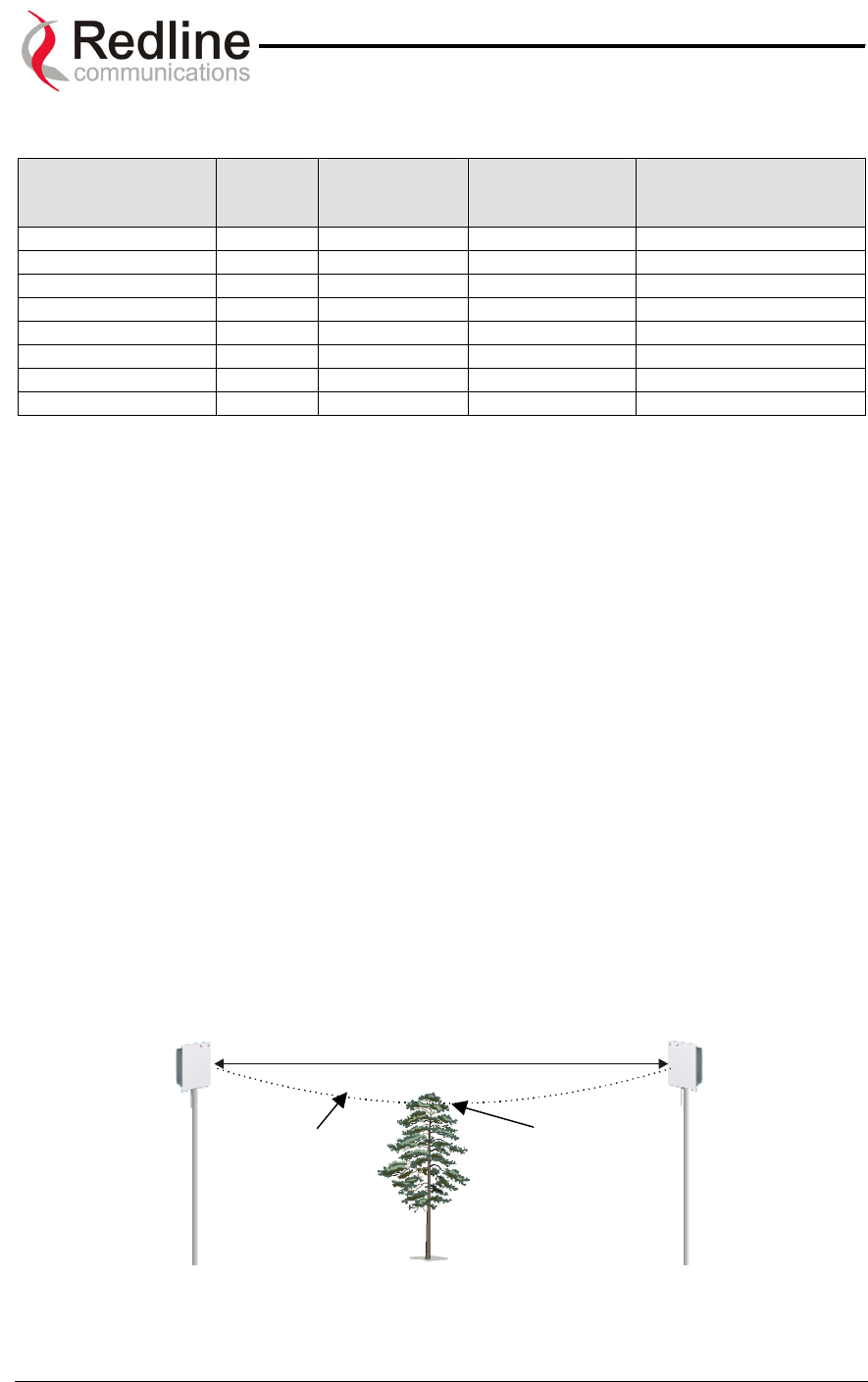
AN-50 System User Manual
Redline Communications …..solving the first mile challenge.
Table 7: Modulation Scheme vs. Data Rate
Modulation Coding
Rate
Over The Air
Rate (Mbps)
Uncoded
Burst Rate
(Mbps)
Average Ethernet
Rate (Mbps)
BPSK ½ 12 6 5.7
BPSK ¾ 12 9 8.4
QPSK ½ 24 12 11.2
QPSK ¾ 24 18 16.5
16 QAM ½ 48 24 21.6
16 QAM ¾ 48 36 31.4
64 QAM ⅔ 72 48 40.5
64 QAM ¾ 72 54 44.9
As indicated in the table above, higher order modulation schemes require greater S/N to
maintain the same BER performance. The noise in this case is defined as the noise floor
of the receiver, i.e., it assumes no interference from other sources (interference from
other sources are addressed below). The main path calculation for determining range
performance is given as:
RSL = Ptx + Gtx – FSL + Grx
Where:
Ptx is the transmit power level in dBm
Gtx is the transmit antenna gain in dB
FSL is the free space loss attenuation in dB, and
Grx is the receive antenna gain in dB
The FSL value is dependent on the range between the two terminals, the type of terrain
over which the link is deployed, and whether or not the link is operating line of sight
(LOS), optical line of sight (OLOS) or non-LOS (NLOS). The LOS FSL calculation is well
understood and easy to calculate, and relies on the fact there is absolutely no obstacle
near the direct path. The precise method for determining the amount of clearance
required for LOS involves making use of a factor known as the Fresnel zone. A Fresnel
zone is defined as a path difference of λ/2 away from the direct path, as shown in Figure
39. A "cleared LOS" link assumes there are no obstacles within 60% of the first Fresnel
zone of the direct path. The diagram below illustrates OLOS conditions, where a treetop
is within the first Fresnel zone, and a clear direct path exists between the antennas.
First
Fresnel
Zone
Obstruction within
first Fresnel Zone
Figure 39: Fresnel Zone Obstruction
Page 64 of 84
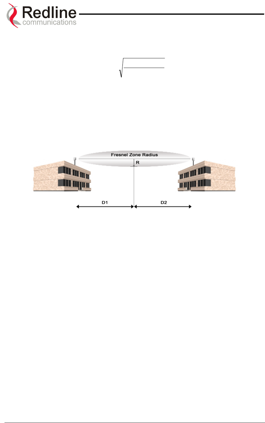
AN-50 System User Manual
Redline Communications …..solving the first mile challenge.
The formula for calculating the radius of the first Fresnel zone, as depicted in Figure 40,
is given as:
)21(*
2*1
1.72 DDf
DD
R+
= (ft)
where,
- D1 and D2 are the distances from the terminals to the point of interest
(in miles), and
- f is the frequency (in GHz)
(Note: multiply results by 0.3048 to obtain a solution in meters)
Figure 40: Fresnel Zone Radius Calculation
Specific FSL formulas are required to deal with this NLOS phenomenon. There are
many NLOS calculations available from established institutions including the Institute of
Electrical and Electronics Engineers (IEEE) and International Telecommunications Union
(ITU), who are chartered with developing standardized calculations. The Redline Link
Budget Tool is built upon these formulas; however, it is important to bear in mind that the
calculations are an estimate only, with relatively large standard deviations (5-15 dB)
depending on the exact deployment scenario and obstacle characteristics.
The last element to consider in the path calculation is the signal to noise (S/N) ratio,
which is defined as:
S/N = RSL – Smin
where,
Smin is the receiver sensitivity expressed in dBm.
The Smin is determined by the thermal noise generated by the amplifier as well as the
bandwidth of the filter used in the receiver front end. It defines the power level at which
the receiver is sensitive enough to properly detect the signal. For the AN-50 operating in
a channel spacing of 20 MHz, the Smin is approximately –96 dBm.
To ensure the link is sufficiently robust to deal with unexpected attenuation effects and
seasonal fades, the S/N must be set higher than the S/Nmin specified in Table 7. The
difference between these two levels is called the Fade Margin (FM). FM is similar to a
Page 65 of 84

AN-50 System User Manual
Redline Communications …..solving the first mile challenge.
"power reserve", in which extra power is designed into the link budget to deal with
additional fades arising from such factors as climatic conditions (seasonal), multipath
dispersions, and shadowing effects from natural (foliage) and man-made obstacles
(buildings). The FM is determined by the availability one desires. Availability is defined
as the amount of time (expressed in % per year) that a link properly detects the signal.
"Properly” in this case is a BER that is less than 10-9. The table below describes the
outage period per year that corresponds to the different availability values.
Table 8: Availability Versus Outage Time
Availability (%) Outage Period Per Year
99.9 8.8 hours
99.99 53 minutes
99.999 5.3 minutes
99.9999 32 seconds
It is recommended that the link be designed for availability greater than 99.99%. The tool
automatically calculates the estimated required fade margin over distance to achieve this
availability.
A key advantage of the Redline product is that it features a transmission correction
scheme called Automatic Repeat Request (ARQ). The ARQ algorithm essentially
detects when a packet(s) has been lost, due to fading, and makes a request to the
remote system to re-transmit the lost packet(s). This feature provides an equivalent link
budget gain of over 5 dB, which translates directly to an improved margin.
Another key advantage of the Redline product is that it features dynamic adaptive
modulation, i.e., the system selects the modulation scheme automatically on a burst-by-
burst basis, based on the measured S/N response. In this manner, the network is
constantly balanced for the optimum spectral efficiency, no matter what propagation
conditions prevail. Higher order modulation schemes (e.g., 64 QAM) are typically
deployed at reduced ranges while lower order modulation schemes (e.g., BPSK) are
implemented at long distances.
A sample link budget is shown in Figure 41 for the AN-50 system operating in 64 QAM,
3/4 code rating, providing a net burst throughput of 54 Megabits per second (Mbps). This
provides an average throughput of 43 Mbps to the Ethernet port. The calculation is
performed for LOS, however the graph (shown in Figure 42 below) also covers the
OLOS and NLOS conditions.
Page 66 of 84
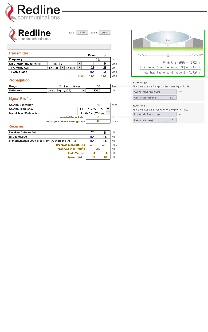
AN-50 System User Manual
Redline Communications …..solving the first mile challenge.
Figure 41: Link Budget For 64 QAM ¾ Code Rate
Page 67 of 84
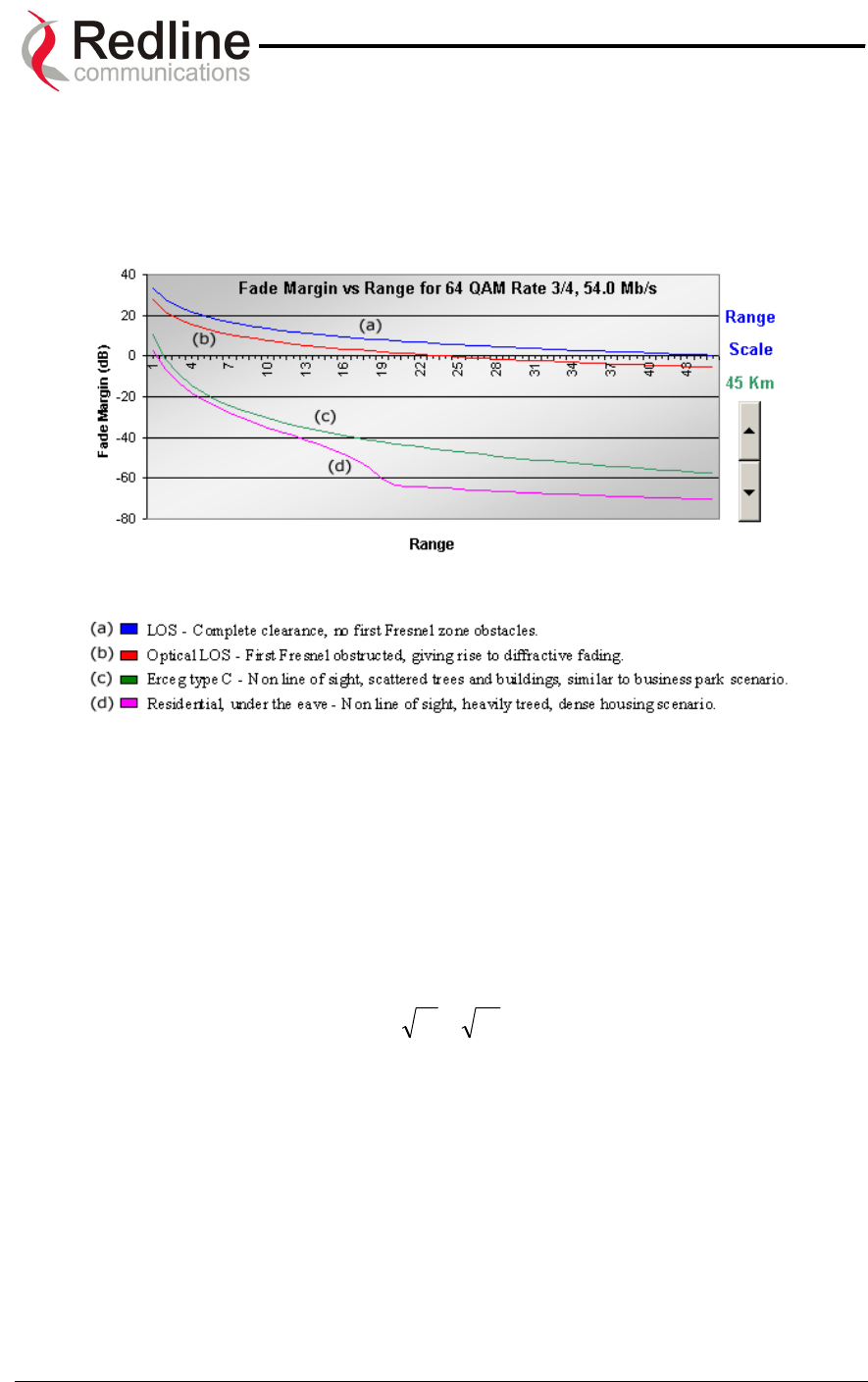
AN-50 System User Manual
Redline Communications …..solving the first mile challenge.
A fade margin graph for this link budget is given in Figure 42 below for four conditions:
LOS (a - blue line), OLOS with the first Fresnel zone obstructed (b - red line), NLOS
scattered trees and buildings (c - green line) and heavily treed residential NLOS (d -
magenta line).
Figure 42: Fade Margin Graphs For LOS, OLOS and NLOS
The graph assumes a fade margin of 3 dB. The effects of rain at UNII bands are
negligible, hence are not included in the link budget.
It is important to note the link calculation assumes that the Earth’s curvature is not
blocking the propagation path. The equation for determining the distance at which the
Earth will cause blockage is called the Radar Horizon, and is given as follows:
Rh=)(1.4 21 hh + (km)
where,
h1 is the height of terminal 1 (m)
h2 is the height of terminal 2 (m)
The table below specifies the horizon distance (km) that can be achieved for different
terminal heights ranging from 10 to 70 m above mean terrain level.
Page 68 of 84

AN-50 System User Manual
Redline Communications …..solving the first mile challenge.
Table 9: Radar Horizon Ranges For Different Terminal Heights (H1 and H2)
H2
10 20 30 40 50 60 70
10 25.9 31.3 35.4 38.9 42.0 44.7 47.3
20 31.3 36.7 40.8 44.3 47.3 50.1 52.6
30 35.4 40.8 44.9 48.4 51.4 54.2 56.8
40 38.9 44.3 48.4 51.9 54.9 57.7 60.2
50 42.0 47.3 51.4 54.9 58.0 60.7 63.3
60 44.7 50.1 54.2 57.7 60.7 63.5 66.1
H1
70 47.3 52.6 56.8 60.2 63.3 66.1 68.6
Page 69 of 84

AN-50 System User Manual
Redline Communications …..solving the first mile challenge.
1
10
0.
.
G
Gl
lo
os
ss
sa
ar
ry
y
O
Of
f
T
Te
er
rm
ms
s
AN-50 Redline Communications’ Access Node-50 Broadband Fixed
Wireless (BFW) system.
Antenna A device for transmitting and/or receiving a radio frequency
(RF). Antennas vary in design and frequencies supported.
Antenna Gain The measure of antenna performance relative to a theoretical
antenna called an isotropic antenna.
ARQ Automatic Repeat Request. This is the protocol used over the
air for error correction.
Beamwidth The angle of signal coverage provided by an antenna.
BFW Broadband Fixed Wireless
Bps (Bits Per Second) A unit of measurement for the rate at which data is transmitted.
BPSK Binary Phase Shift Keying.
BS Base Station
Channel A communications path wide enough to permit a single RF
transmission.
CID Channel Identification
CIR Committed Information rate
DB A ratio expressed in decibels.
dBi A ratio, measured in decibels, of the effective gain of an
antenna compared to an isotropic antenna.
DBm Decibels above a milliwatt
DHCP Dynamic Host Configuration Protocol. A DHCP server will
automatically issue IP addresses within a specified range to
devices on a network.
Directional Antenna An antenna that concentrates transmission power into one
direction.
Encryption For the purposes of privacy, the transformation of data into an
unreadable format until reformatted with a decryption key.
Ethernet A LAN architecture using a bus or star topology
FD Full Duplex. Refers to the transmission of data in two directions
simultaneously (i.e. a telephone)
FWA Fixed Wireless Access
Gain The ratio of the output amplitude of a signal to the input
amplitude of a signal. Typically expressed in decibels (dB).
Gateway A network point that acts as an entrance to another network.
GHz Gigahertz. 1,000,000,000 Hz, or 1,000 MHz
GUI Graphical User Interface
Hertz (Hz) The international unit for measuring frequency, equivalent to
the number of cycles per second. One megahertz (MHz) is one
million Hertz. One gigahertz (GHz) is one billion Hertz.
IF Intermediate Frequency.
IP (Internet Protocol) See TCP/IP.
Isotropic A theoretic construct of an antenna that radiates its signal 360
degrees both vertically and horizontally—a perfect sphere.
Generally used as a reference.
IXC (Inter-exchange Carrier) A long-distance phone company.
LAN (Local Area Network) A data communications network, typically within a building or
campus linking computers, printers and other devices together.
LEC (Local Exchange The traditional local wired phone company.
Page 70 of 84

AN-50 System User Manual
Redline Communications …..solving the first mile challenge.
Carriers)
LED Light Emitting Diode
LOS Line Of Sight. A clear direct path between two antennas, with
no obstructions within the first Fresnel zone.
MAC (Media Access Control) A unique number assigned to a network device. It corresponds
to the ISO Network Model Layer 2 data link layer.
MHz Megahertz. 1,000,000 Hz
Modem
(MOdulator/DEModulator)
A hardware device which converts digital data into analog and
vice versa.
Modulation Any of several techniques for combining user information with a
transmitter carrier signal.
Multipath The radio echoes created as a radio signal bounces off of
objects.
NLOS Non Line Of Sight. Completely obstructed path between two
antennas.
OFDM Orthogonal Frequency Division Multiplexing. OFDM spreads
data to be transmitted over a large number of orthogonal
carriers.
OLOS Optical Line Of Sight. A clear direct path between two
antennas, with obstructions within the first Fresnel zone.
Packet A bundle of data organized in a specific way for transmission.
The three principal elements of a packet include the header,
the text, and the trailer (error detection and correction bits).
PHY (Physical Layer) Provides for the transmission of data through a
communications channel by defining the electrical, mechanical,
and procedural specifications.
PIR Peak Information rate
PMP Point to Multipoint
PTP Point to Point
QAM Quadrature Amplitude Modulation
QoS Quality of Service
QPSK Quadrature Phase Shift Keying
Receiver Sensitivity A measurement of the weakest signal a receiver can receive
and still correctly translate it into data.
RF Radio Frequency
Rx Receiver
S/N Signal to Noise Ratio
SINADR Signal to noise and distortion ratio.
SS Subscriber Station
TCP/IP (Transmission
Control Protocol/Internet
Protocol)
The standard set of protocols used by the Internet for
transferring information between computers, handsets, and
other devices.
TFTP Trivial File Transfer Protocol
Tx Transmitter
UNII Unlicensed National Information Infrastructure
Page 71 of 84

AN-50 System User Manual
Redline Communications …..solving the first mile challenge.
1
11
1.
.
A
Ap
pp
pe
en
nd
di
ix
x
3
3
–
–
S
Su
up
pp
po
or
rt
t
F
Fo
or
r
T
TD
DM
M
U
Us
si
in
ng
g
T
Th
hi
ir
rd
d
P
Pa
ar
rt
ty
y
U
Un
ni
it
ts
s
802.1p QoS
The AN-50 uses IEEE 802.1p to ensure QoS to TDM based applications such as
mobility backhaul and enterprise PBX traffic. IEEE 802.1p allows the wireless transmit
queue to be split into two (high and low priority) queues. Ethernet packets are queried to
determine if they are priority tagged. Packets tagged with a priority value greater than or
equal to four are automatically placed in the high priority queue. All other packet go into
a default queue. The AN-50 always services the traffic in its high priority queue before
the default, low priority queue. A low priority packet will only be transmitted once the
high priority queue is empty.
Flow Control
For improved traffic handling the AN50 supports standard IEEE 802.3x flow control.
Upon reception of a pause control frame, the Ethernet port will not transmit the next
normal frame until the timer specified in the pause control frame expires, or another
pause control frame is received. During the flow controlled period, only flow control
packets will be transmitted between the AN-50 and its interfacing device (i.e. Switch/
Router or Third Party T1/E1 Unit).
The AN-50 will also transmit pause control frames based on the availability of its own
internal resources, including buffers, transmit queues and receive queues.
Ethernet traffic can easily exceed the total capacity of a wireless link and thereby trigger
indiscriminate packet discarding on all traffic streams. To avoid this condition the AN-50
also provides a dynamic traffic shaping capability that continually adjusts itself to the
current wireless throughput conditions. With adaptive modulation enabled, wireless
throughput can automatically decrease, in order to maintain acceptable Packet Error
Rates. In response to such a decrease, the AN-50 will also automatically throttle-back
(traffic shape) the lower priority traffic streams by first discarding the packets in its
default Tx queue.
Upon receiving additional packets, the AN-50’s will issue a pause control frame to its
interfacing device, requesting a pause in transmission.
Once wireless resources are again freed up, a new pause control frame is issued to
resume transmission.
Using a Third Party T1/E1 Unit with AN-50
While it is beneficial for the interfacing device to support 802.3x (i.e. interpret and act on
pause frames issued by the AN-50) in data only applications, it is essential that the Third
Party T1/E1 Unit be configured to ignore the reception of 802.3x pause frame in order to
ensure uninterrupted transmission of the TDM traffic.
Note: For more information, contact your Redline certified partner or system integrator or
check our support site for additional TDM documents.
Page 72 of 84
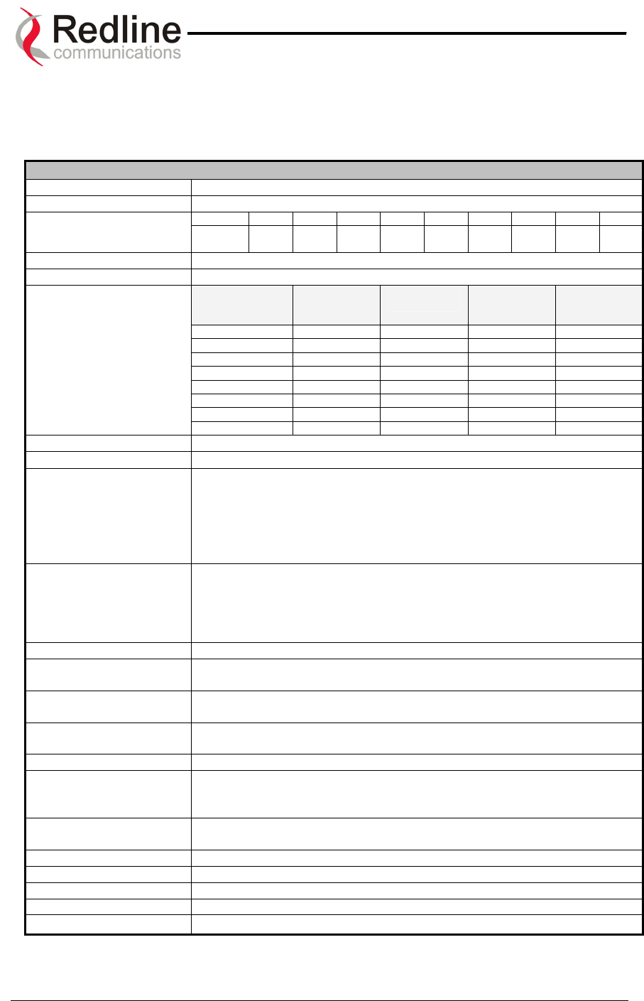
AN-50 System User Manual
Redline Communications …..solving the first mile challenge.
1
12
2.
.
S
Sp
pe
ec
ci
if
fi
ic
ca
at
ti
io
on
ns
s
12.1. AN-50 System Specifications
AN-50 System Specifications
System Capability Non-line-of-sight operations, PTP / PMP mode
RF Band 5.725 - 5.825 GHz (UNII Band)
Channel 1 1A 2 2A 3 3A 4 4A 5
Channel Center
Frequencies Freq. 5.735
GHz
5.745
GHz
5.755
MHz
5.765
GHz
5.775
GHz
5.785
GHz
5.795
GHz
5.805
GHz
5.815
GHz
Channel Size 20 MHz
RF Dynamic Range > 50 dB
Modulation Coding Rate Over The Air
Rate (Mbps)
Uncoded
Burst Rate
(Mbps)
Average
Ethernet
Rate (Mbps)
BPSK ½ 12 6 5.7
BPSK ¾ 12 9 8.4
QPSK ½ 24 12 11.2
QPSK ¾ 24 18 16.5
16 QAM ½ 48 24 21.6
16 QAM ¾ 48 36 31.4
64 QAM ⅔ 72 48 40.5
Modulation/Throughput
64 QAM ¾ 72 54 44.9
Maximum Tx Power -5 to +26 dBm (region specific) *
Rx Sensitivity -86 dBm at 6 Mbps
IF Cable • Maximum length up to 250 ft (76m) using RG6U / 500 ft (152m)
using high-grade RG11U
• Maximum allowable losses at 2.5 GHz:
RG6: 10 dB/30m (100 feet) at 250C
RG11: 5 dB/30m (100 feet) at 250C
• Multiplexed IF, DC power, control (Tx/Rx, AGC, APC)
Network Attributes • Transparent bridge
• DHCP passthrough
• VLAN passthrough
• 802.3x Ethernet flow control
• 802.1p Network traffic prioritization
Max Channel IDs (CID) 1k CIDs, one CID per Subscriber Station
Provisioning Best effort, Peak Information Rate (PIR) and Common Information
Rate (CIR)
Modulation Dynamic Adaptive Modulation (bi-directional) auto selects:
• BPSK • QPSK • 16 QAM • 64 QAM
Over The Air
Encryption
Proprietary 128-bit encryption
Coding Rates 1/2, 3/4 and 2/3
MAC • Point to point or Point to Multipoint
• Automatic Repeat Request (ARQ) error correction
• Concatenation/Fragmentation
Range • Over 10 km / 6 miles non-line-of sight
• Over 50 km / 30 miles line-of-sight
Network Services Transparent to 802.3 services and applications
Duplex Technique Dynamic TDD (time division duplex)
Wireless Transmission OFDM (orthogonal frequency division multiplexing)
Backhaul Connection 10/100 Ethernet (RJ45)
System Configuration • Web interface
* Note: In some countries outside of North America, the Max. Operational Power Per Channel with a given
antenna is limited in accordance to maximum allowable EIRP levels for the region.
Page 73 of 84

AN-50 System User Manual
Power Requirements 110/220/240 VAC (auto-sensing) 50/60 Hz 39W maximum
Operating Temperature
Range
AN-50 Terminal: 32F to 131F / 0C to +55C
T-58: -40F to +140F / -40C to +60C
Wind Loading AN-50 Radio: 137 mph / 220 km/hr
Physical Configuration AN-50 terminal, AN-50 Radio (4.5, 9, 60 and 90 degree
antennas – check Redline WEB site for a full FCC approved list of
antennas)
AN-50 Dimensions 17” x 12” x 1.75” / 431.8 mm x 304.8 mm x 44.45 mm
Component Weights
AN-50 Terminal ……………………………………………. 2.0 kg
T-58 Transceiver …………………………………………… 1.0 kg
Vertical Mast Bracket Kit ………………………………….. 3.0 kg
Universal Mast Bracket Kit ……………………………….. 1.5 kg
Vertical Mast Bracket Hardware Kit ……………………… 0.5 kg
Universal Mast Bracket Hardware Kit ……………………. 0.5 kg
Antenna, 9° ………………………………………… 1.0 kg
Cable, F Male/F Male, RG6, Messenger Wire, 100 ft….. 1.3 kg
Antenna, 4.5°, ……………………………………… 5.0 kg
Redline Communications …..solving the first mile challenge.
AN-50 System Specifications continued….
Page 74 of 84
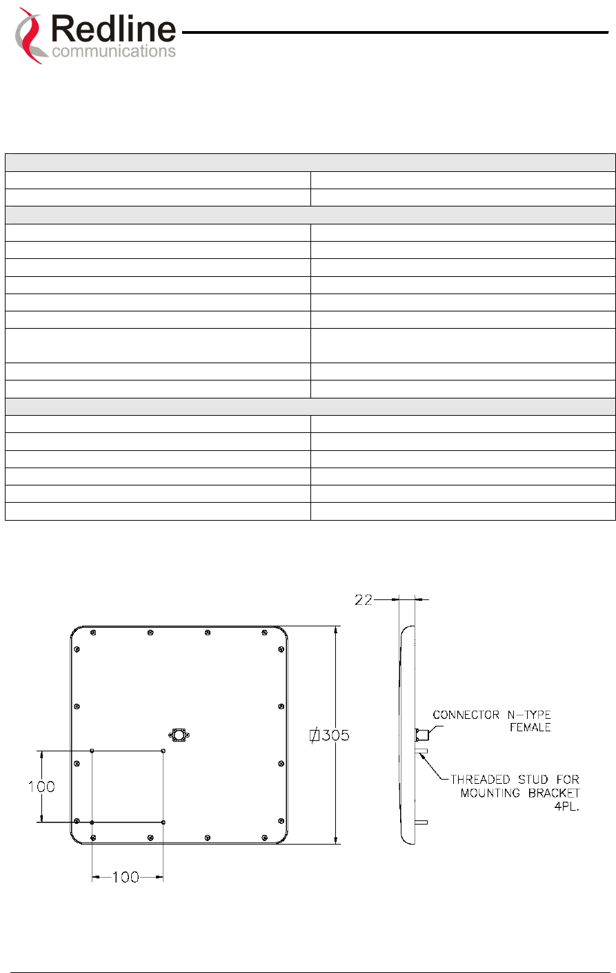
AN-50 System User Manual
Redline Communications …..solving the first mile challenge.
MTI part No. MT-485002
12.2. Nine Degree Antenna Specifications
9 Degree Antenna
Type Planar Array
Regulatory Compliance ETSI EN 302 085 V1.1.2 (2001-02)
Electrical
Frequency Range 5.15-5.35 GHz and 5.725-5.875 GHz
Gain 23 dBi (min)
VSWR 1.7:1 (max)
3 dB BW 9° (typ.)
Polarization Linear (Vertical or Horizontal)
Cross Polarization -28 dB (max)
Sidelobe Level ETSI EN 302 085 V1.1.2 (2001-02)
Range 1TS1- TS3
F/B Ratio -32 dB (max)
Lightning Protection DC Grounded
Mechanical
Dimensions (LxWxD) 305 x 305 x 25 mm
Weight 1.5 kg
Connector N-Type Female
Temperature (operating) -45°C to +70°C
Wind Load (Survival) 220 km/hr
Radial Ice Load 25 mm
All dimensions in mm
Page 75 of 84
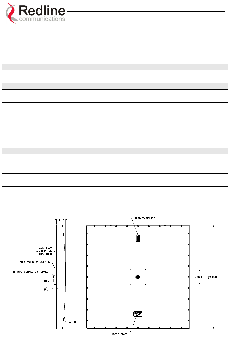
AN-50 System User Manual
Redline Communications …..solving the first mile challenge.
12.3. Four Point Five Degree Antenna Specifications
4.5 Degree Antenna
Type Planar Array
Regulatory Compliance ETSI EN 302 085 V1.1.2 (2001-02)
Electrical
Frequency Range 5.25-5.85 GHz
Gain 28 dBi (min)
VSWR 1.5:1 (typ.) 1.7:1 (max)
3 dB BW 4.5° (typ.)
Polarization Linear (Vertical or Horizontal)
Cross Polarization -28 dB (max)
Sidelobe Level ETSI EN 302 085 V1.1.2 (2001-02)
F/B Ratio -40 dB (max)
Lightning Protection DC Grounded
Mechanical
Dimensions (LxWxD) 600 x 600 x 55 mm
Weight 5 kg (max)
Connector N-Type Female
Temperature (operating) -45°C to +70°C
Wind Load (Survival) 220 km/hr
Radial Ice Load 25 mm
All dimensions in mm
Page 76 of 84

AN-50 System User Manual
Redline Communications …..solving the first mile challenge.
12.4. Sixty Degree Antenna Specifications
600 5.8 GHz FLAT PANEL BASE STATION ANTENNA
ELECTRICAL
FREQUENCY RANGE 5.15-5.875 GHz
GAIN 15 dBi (min)
VSWR 1.7:1 (max)
12 dBi Azimuth BEAMWIDTH 600 -4 /+70 (min)
ELEVATION 3 dB BEAMWIDTH 100 +/- 10
POLARIZATION Horizontal
AZIMUTH SIDELOBES LEVEL -30 dB (max) at +/-900
ELEVATION NULL FILL BELOW HORIZON:
- 1ST NULL
- 2nd NULL
-15 dB (min) at 100
-25 dB (min) at 200
CROSS POLARIZATION -24 dB (max)
F/B RATIO -30 dB (max)
INPUT IMPEDANCE 50 (ohm)
POWER 6W
MECHANICAL
DIMENSIONS (L x W x D) 436 x 250 x 10mm (max)
WEIGHT 2.2 Kg
CONNECTOR N-TYPE
RADOME Plastic
BASE PLATE Aluminum anodized
RADIAL ICE AND SNOW 25mm
WIND SPEED (SURVIVAL) 220 Km/h
TEMPERATURE (Operating) -45C +70 C
Page 77 of 84

AN-50 System User Manual
Redline Communications …..solving the first mile challenge.
12.5. Ninety Degree Antenna Specifications
900 5.8 GHz FLAT PANEL BASE STATION ANTENNA
REGULATORY COMPLIANCE ETSI EN 302 085 V1.1.2
ELECTRICAL
FREQUENCY RANGE 5.15-5.875 GHz
GAIN 14 dBi (min)
VSWR 1.7:1 (typ)
AZIMUTH 3 dB BEAMWIDTH 90° +8°/-6°
ELEVATION 3 dB BEAMWIDTH 10° ±1°
POLARIZATION Vertical
AZIMUTH SIDELOBES LEVEL -30dB at ± 135°
ELEVATION NULL FILL BELOW HORIZON:
- 1ST NULL
- 2nd NULL
-15 dB (min) at 10°
-25 dB (min) at 20°
CROSS POLARIZATION -25 dB (nom), -21dB (max)
F/B RATIO -30 dB (max)
INPUT IMPEDANCE 50 (ohm)
POWER 6W
MECHANICAL
DIMENSIONS (LxWxD) 436 x 250 x 10(max)
WEIGHT 2.2 Kg
CONNECTOR N-TYPE
RADOME Plastic
BASE PLATE Aluminum with chemical conversion
coating
RADIAL ICE AND SNOW 25mm
WIND SPEED (SURVIVAL)
TEMPERATURE (Operating) -45C +70 C
Page 78 of 84
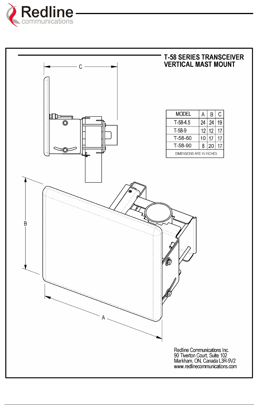
AN-50 System User Manual
Redline Communications …..solving the first mile challenge.
12.6. Vertical Mount Dimensions
Page 79 of 84
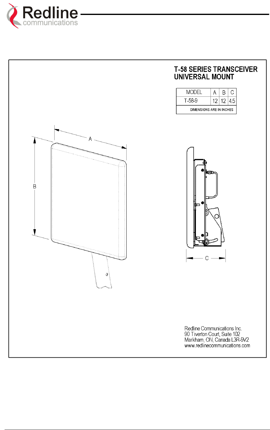
AN-50 System User Manual
Redline Communications …..solving the first mile challenge.
12.7. Universal Mount Dimensions
Accommodates 9
0
antennas
Page 80 of 84
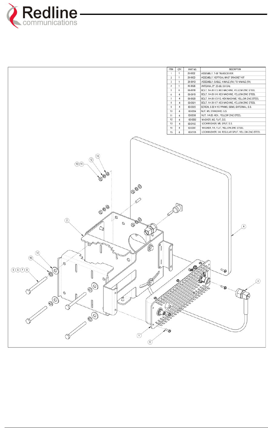
AN-50 System User Manual
Redline Communications …..solving the first mile challenge.
12.8. Vertical Mount Assembly
The vertical mount may be used for 4.50 and 90 antennas. Assembly for the 90 antenna
is shown here.
Page 81 of 84
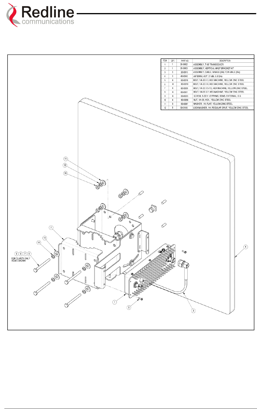
AN-50 System User Manual
Redline Communications …..solving the first mile challenge.
The vertical mount may be used for 4.50 and 90 antennas. Assembly for the 4.50
antenna is shown below.
Page 82 of 84
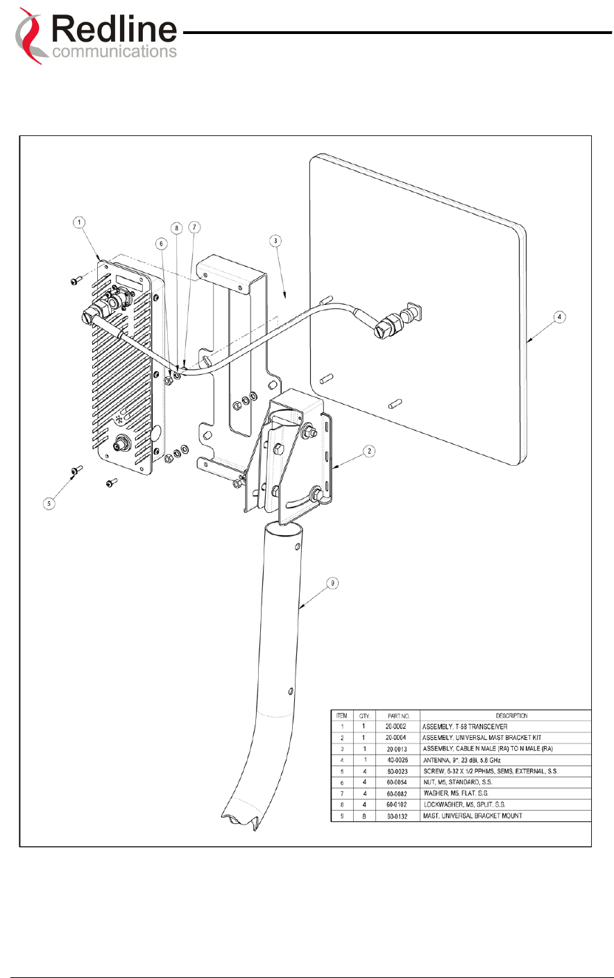
AN-50 System User Manual
Redline Communications …..solving the first mile challenge.
12.9. Universal Mount Assembly
The universal mount may be used for 90 antennas only.
Page 83 of 84

90 Tiverton Court • Suite 102 • Markham, Ontario • Canada • L3R 9V2
www.redlinecommunications.com