Redline Communications REM2500M WiMAX 16e 2.5-2.7GHz Outdoor CPE User Manual 70 00121 01 00
Redline Communications Inc. WiMAX 16e 2.5-2.7GHz Outdoor CPE 70 00121 01 00
UserManual.wiki
>
Redline Communications
>
REM2500M User Manual
User Manual
Navigation menu
Upload a User Manual
Namespaces
Wiki Guide
HTML
PDF
Info
Views
User Manual
Discussion / Help
Navigation

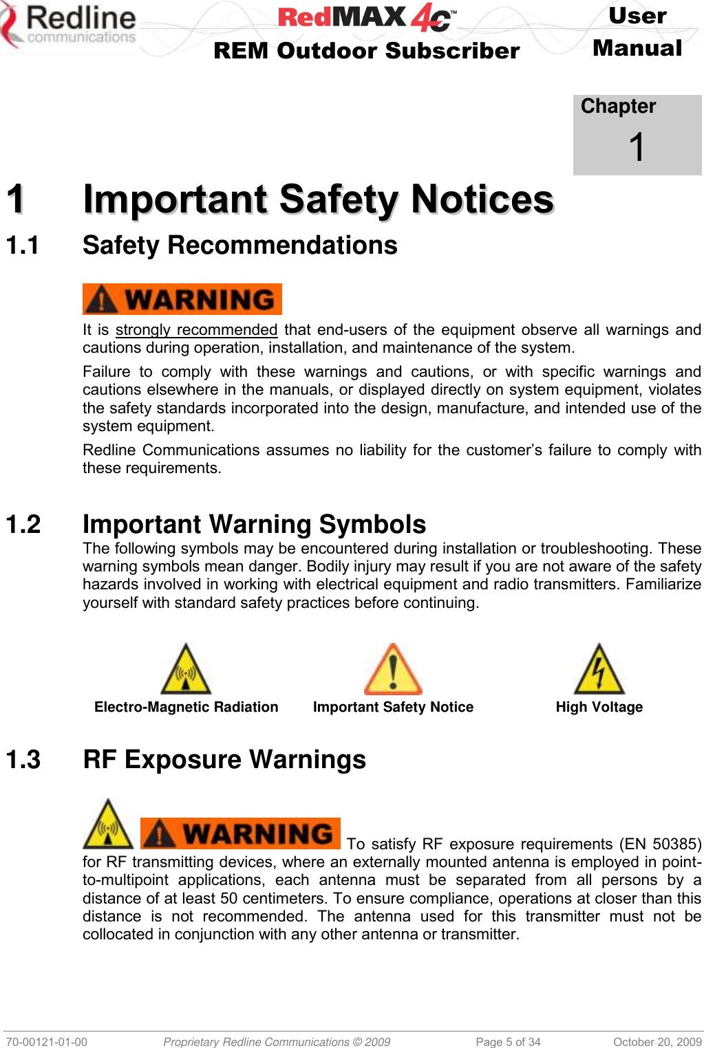
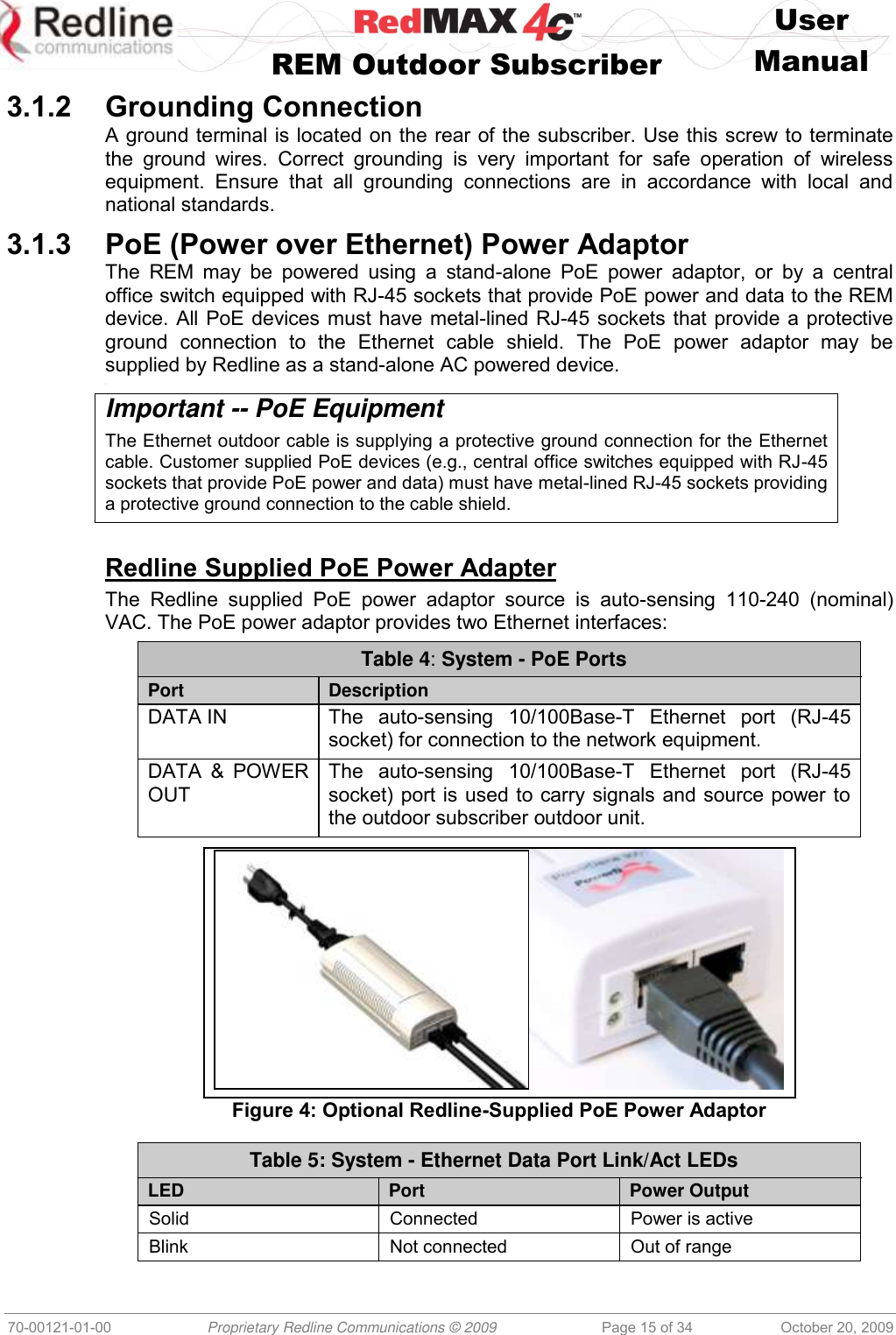
![User REM Outdoor Subscriber Manual 70-00121-01-00 Proprietary Redline Communications © 2009 Page 8 of 34 October 20, 2009 1.7 Europe – EU Declaration of Conformity This device complies with the essential requirements of the R&TTE Directive 1999/5/EC. The following test methods have been applied in order to prove presumption of conformity with the essential requirements of the R&TTE Directive 1999/5/EC: IEC 60950-1: 2001 (1st edition) Safety of Information Technology Equipment EN50385 Product standard to demonstrate the compliance of radio base stations and fixed terminal stations for wireless telecommunication systems with the basic restrictions or the reference levels related to human exposure to radio frequency electromagnetic fields (110 MHz - 40 GHz) - General public EN 301 489-1 Electromagnetic compatibility and Radio Spectrum Matters (ERM); Electromagnetic Compatibility (EMC) standard for radio equipment and services; Part 1: Common technical requirements EN 301 489-4 Electromagnetic compatibility and radio spectrum matters (ERM); Electromagnetic compatibility (EMC) standard for radio equipment and services; Part 4: Specific conditions for fixed radio links and ancillary equipment and services EN 302 544-1 (REM2500M 2.5 GHz Systems Only) Broadband Data Transmission Systems operating in the 2 500 MHz to 2 690 MHz frequency band; Part 1: TDD Base Stations; Harmonized EN covering the essential requirements of article 3.2 of the R&TTE Directive EN 302 326-2 (REM3500M 3.5 GHz systems Only) Fixed Radio Systems; Multipoint Equipment and Antennas; Part 2: Harmonized EN covering the essential requirements of article 3.2 of the R&TTE Directive for Digital Multipoint Radio Equipment 0678 Table 1: Notices - R&TTE Community Language CE Declarations Country Notice Česky [Czech] [Jméno výrobce] tímto prohlašuje, že tento [typ zařízení] je ve shodě se základními požadavky a dalšími příslušnými ustanoveními směrnice 1999/5/ES. Dansk [Danish] Undertegnede [fabrikantens navn] erklærer herved, at følgende udstyr [udstyrets typebetegnelse] overholder de væsentlige krav og øvrige relevante krav i direktiv 1999/5/EF. Deutsch [German] Hiermit erklärt [Name des Herstellers], dass sich das Gerät [Gerätetyp] in Übereinstimmung mit den grundlegenden Anforderungen und den übrigen einschlägigen Bestimmungen der Richtlinie 1999/5/EG befindet. Eesti [Estonian] Käesolevaga kinnitab [tootja nimi = name of manufacturer] seadme [seadme tüüp = type of equipment] vastavust direktiivi 1999/5/EÜ põhinõuetele ja nimetatud direktiivist tulenevatele teistele asjakohastele sätetele. English Hereby, [name of manufacturer], declares that this [type of equipment] is in compliance with the essential requirements and other relevant provisions of Directive 1999/5/EC.](https://usermanual.wiki/Redline-Communications/REM2500M/User-Guide-1200072-Page-8.png)
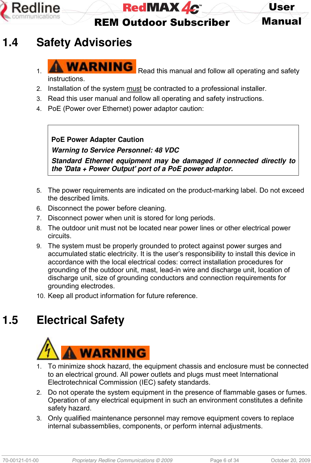
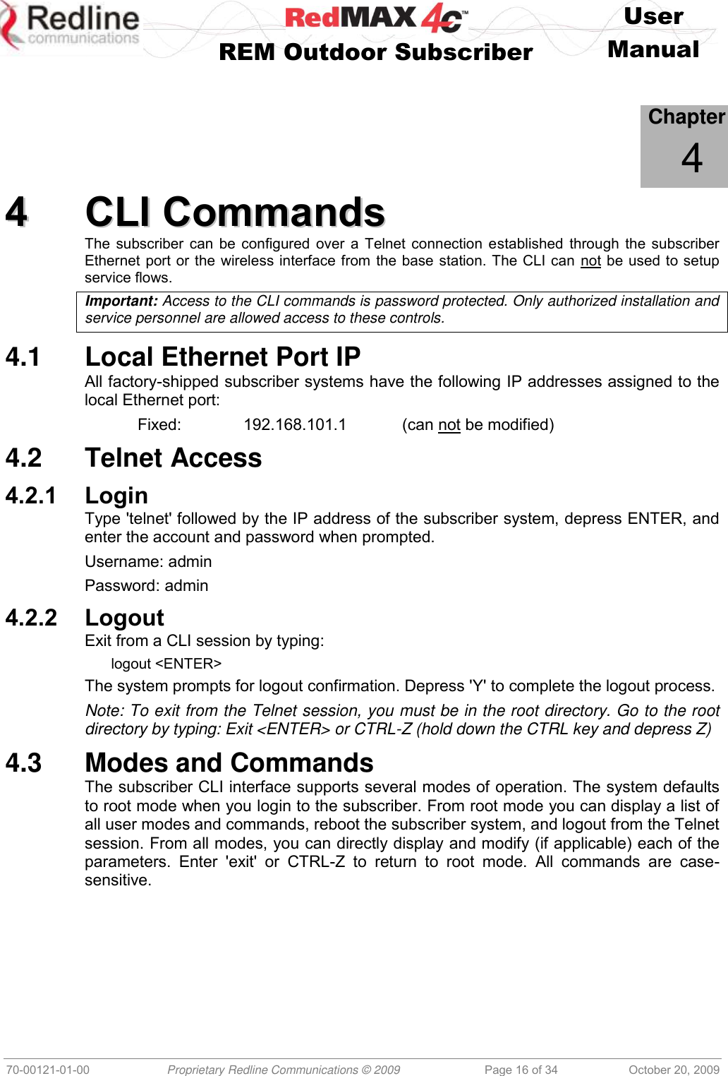
![User REM Outdoor Subscriber Manual 70-00121-01-00 Proprietary Redline Communications © 2009 Page 9 of 34 October 20, 2009 Table 1: Notices - R&TTE Community Language CE Declarations Country Notice Español [Spanish] Por medio de la presente [nombre del fabricante] declara que el [clase de equipo] cumple con los requisitos esenciales y cualesquiera otras disposiciones aplicables o exigibles de la Directiva 1999/5/CE. Ελληνική [Greek] ΜΕ ΣΗΝ ΠΑΡΟΤΑ [name of manufacturer] ΔΗΛΩΝΕΙ ΟΣΙ [type of equipment] ΤΜΜΟΡΦΩΝΕΣΑΙ ΠΡΟ ΣΙ ΟΤΙΩΔΕΙ ΑΠΑΙΣΗΕΙ ΚΑΙ ΣΙ ΛΟΙΠΕ ΥΕΣΙΚΕ ΔΙΑΣΑΞΕΙ ΣΗ ΟΔΗΓΙΑ 1999/5/ΕΚ. Français [French] Par la présente [nom du fabricant] déclare que l'appareil [type d'appareil] est conforme aux exigences essentielles et aux autres dispositions pertinentes de la directive 1999/5/CE. Italiano [Italian] Con la presente [nome del costruttore] dichiara che questo [tipo di apparecchio] è conforme ai requisiti essenziali ed alle altre disposizioni pertinenti stabilite dalla direttiva 1999/5/CE. Latviski [Latvian] Ar šo [name of manufacturer / izgatavotāja nosaukums] deklarē, ka [type of equipment / iekārtas tips] atbilst Direktīvas 1999/5/EK būtiskajām prasībām un citiem ar to saistītajiem noteikumiem. Lietuvių [Lithuanian] Šiuo [manufacturer name] deklaruoja, kad šis [equipment type] atitinka esminius reikalavimus ir kitas 1999/5/EB Direktyvos nuostatas. Nederlands [Dutch] Hierbij verklaart [naam van de fabrikant] dat het toestel [type van toestel] in overeenstemming is met de essentiële eisen en de andere relevante bepalingen van richtlijn 1999/5/EG. Malti [Maltese] Hawnhekk, [isem tal-manifattur], jiddikjara li dan [il-mudel tal-prodott] jikkonforma mal-ħtiġijiet essenzjali u ma provvedimenti oħrajn relevanti li hemm fid-Dirrettiva 1999/5/EC. Magyar [Hungarian] Alulírott, [gyártó neve] nyilatkozom, hogy a [... típus] megfelel a vonatkozó alapvetõ követelményeknek és az 1999/5/EC irányelv egyéb elõírásainak. Polski [Polish] Niniejszym [nazwa producenta] oświadcza, że [nazwa wyrobu] jest zgodny z zasadniczymi wymogami oraz pozostałymi stosownymi postanowieniami Dyrektywy 1999/5/EC. Português [Portuguese] [Nome do fabricante] declara que este [tipo de equipamento] está conforme com os requisitos essenciais e outras disposições da Directiva 1999/5/CE. Slovensko [Slovenian] [Ime proizvajalca] izjavlja, da je ta [tip opreme] v skladu z bistvenimi zahtevami in ostalimi relevantnimi določili direktive 1999/5/ES. Slovensky [Slovak] [Meno výrobcu] týmto vyhlasuje, že [typ zariadenia] spĺňa základné požiadavky a všetky príslušné ustanovenia Smernice 1999/5/ES. Suomi [Finnish] [Valmistaja = manufacturer] vakuuttaa täten että [type of equipment = laitteen tyyppimerkintä] tyyppinen laite on direktiivin 1999/5/EY oleellisten vaatimusten ja sitä koskevien direktiivin muiden ehtojen mukainen. Svenska [Swedish] Härmed intygar [företag] att denna [utrustningstyp] står I överensstämmelse med de väsentliga egenskapskrav och övriga relevanta bestämmelser som framgår av direktiv 1999/5/EG.](https://usermanual.wiki/Redline-Communications/REM2500M/User-Guide-1200072-Page-9.png)
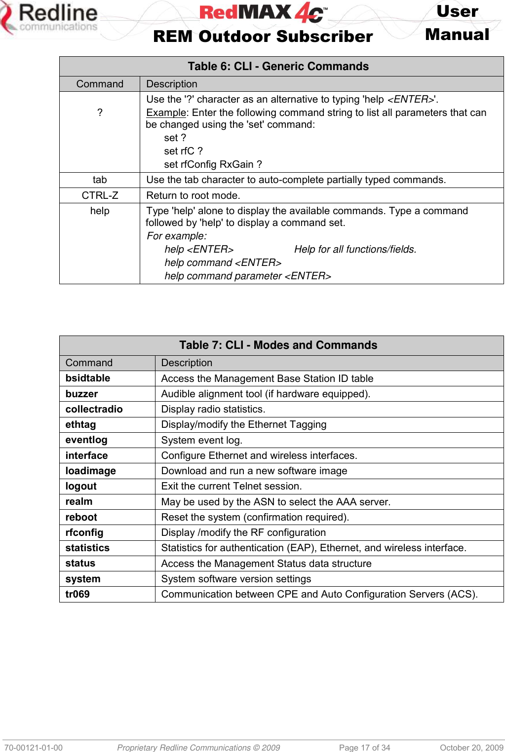
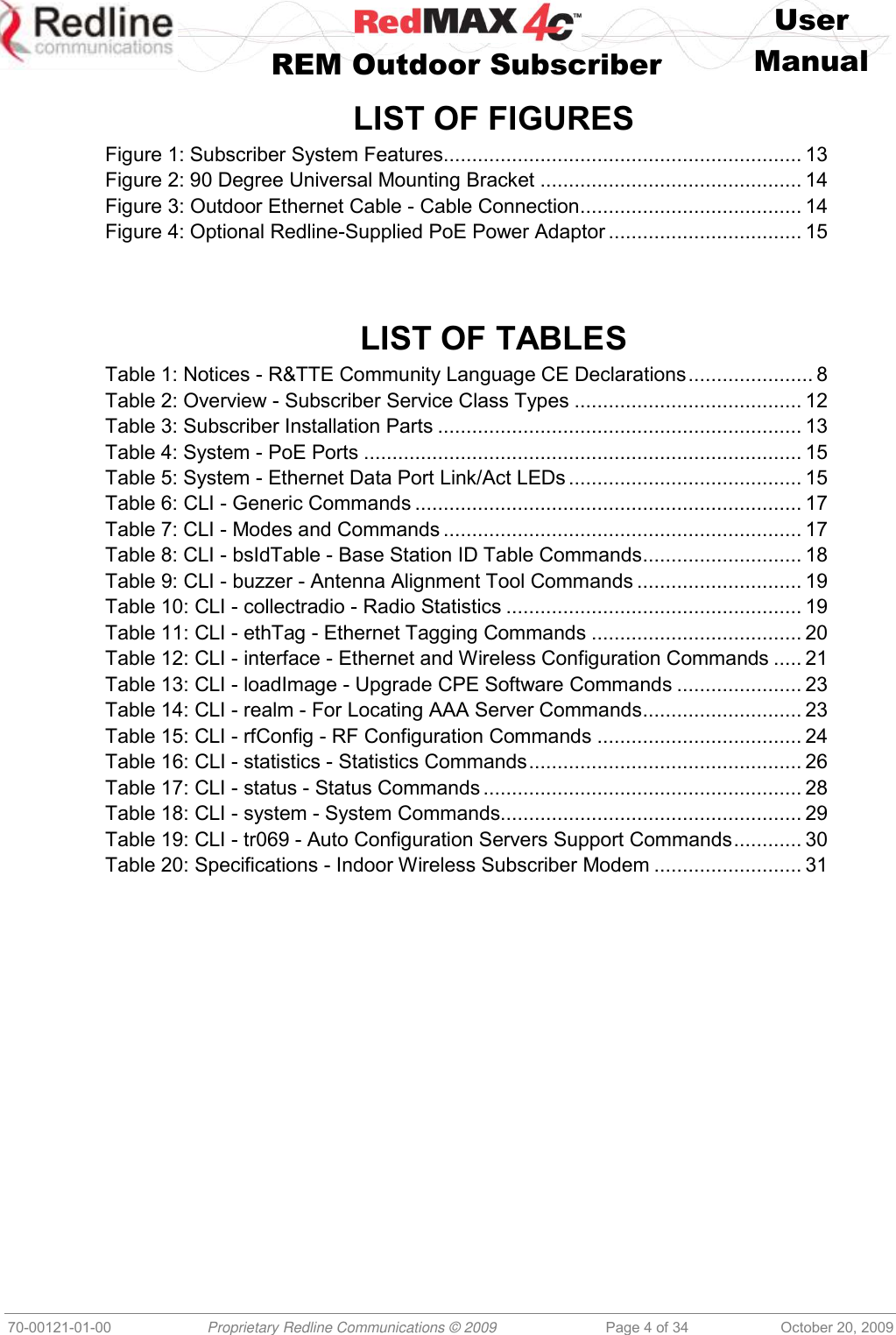
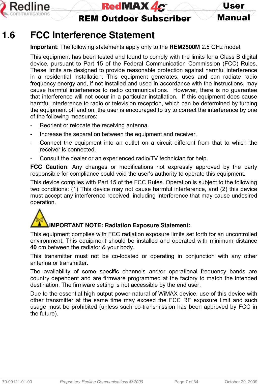
![User REM Outdoor Subscriber Manual 70-00121-01-00 Proprietary Redline Communications © 2009 Page 32 of 34 October 20, 2009 5.2 Subscriber Upgrade Procedure Before Beginning the Upgrade Use the following procedures to upgrade the subscriber. The following items must be addressed before beginning the upgrade: 1. You must obtain the latest subscriber binary files. 2. The subscriber performs all software upgrades using an FTP server: a) The FTP server must be located on the network connected to the subscriber Ethernet port, or be reachable over the air interface. b) The FTP server must have a user account defined as follows: username: target password: secret c) You must copy the subscriber binary file into the default file location for the FTP account (not able to specify a pathname in the upgrade dialog). Update Software Procedure Start a telnet session to the subscriber using the following settings: Login: admin Password: admin Enter the 'loadImage' command. The subscriber will prompt you to enter the following information: Server IP address: [enter address of FTP server] File Name: [enter base station binary file name] The subscriber performs FTP server authentication with user name 'target' and password 'secret' (these settings cannot be altered). The image will be uploaded to the subscriber and saved in the non-volatile memory (flash). The subscriber must be reset to load the new software. Enter the 'reboot' command to reset the unit. The telnet session will be terminated. Example Download Dialog with Subscriber Login: admin Password: admin, welcome to the SS CLI. SUI#> loadImage Server IP Address: [enter ftp server IP address here] File Name: [enter binary file name here] Opening FTP connection.....Done Downloading image ............................................................................................……………… Done Programming update........Done Erasing setup partition. Done. Writing setup partition. Done. Erasing boot block. Done Programming boot block. Done Flash programming complete. SUI#>reboot](https://usermanual.wiki/Redline-Communications/REM2500M/User-Guide-1200072-Page-32.png)