Redline Communications REM2500M WiMAX 16e 2.5-2.7GHz Outdoor CPE User Manual 70 00121 01 00
Redline Communications Inc. WiMAX 16e 2.5-2.7GHz Outdoor CPE 70 00121 01 00
User Manual
70-00121-01-00 Proprietary Redline Communications © 2009 Page 1 of 34 October 20, 2009
Outdoor Wireless Access
Subscriber Modem
REM Series
User Manual
User
REM Outdoor Subscriber Manual
70-00121-01-00 Proprietary Redline Communications © 2009 Page 2 of 34 October 20, 2009
Copyright Information
All rights reserved October 20, 2009. The information in this document is proprietary to
Redline Communications Inc. This document may not in whole or in part be copied,
reproduced, or reduced to any medium without prior consent, in writing, from Redline
Communications Incorporated.
Contact Information:
Redline Communications Inc.
302 Town Centre Blvd. Suite 100
Markham, ON
Canada L3R 0E8
Web site: http://www.redlinecommunications.com
Sales Inquiries:
North American nainfo@redlinecommunications.com
Toll-free sales 1-866-633-6669
International intlinfo@redlinecommunications.com
Support: www.redlinecommunications.com/support/support_portal.html
Document Control:
70-00121-01-00-4C_SS_Outdoor_REM_UserManual-20090914a.doc
Disclaimer
The statements, configurations, technical data, and recommendations in this document
are believed to be accurate and reliable, but are presented without express or implied
warranty. Additionally, Redline makes no representations or warranties, either expressed
or implied, regarding the contents of this product. Redline Communications shall not be
liable for any misuse regarding this product. The information in this document is subject
to change without notice.

User
REM Outdoor Subscriber Manual
70-00121-01-00 Proprietary Redline Communications © 2009 Page 3 of 34 October 20, 2009
TABLE OF CONTENTS
1 Important Safety Notices ....................................................................... 5
1.1 Safety Recommendations ........................................................................ 5
1.2 Important Warning Symbols ..................................................................... 5
1.3 RF Exposure Warnings ............................................................................ 5
1.4 Safety Advisories ..................................................................................... 6
1.5 Electrical Safety ....................................................................................... 6
1.6 FCC Interference Statement .................................................................... 7
1.7 Europe – EU Declaration of Conformity ................................................... 8
1.8 Security Features ................................................................................... 10
1.9 WEEE Product Return Process .............................................................. 10
2 Overview ............................................................................................... 11
2.1 IEEE 802.16e / WiMAX Compliance ...................................................... 11
2.2 PHY Specification .................................................................................. 11
2.3 OFDMA .................................................................................................. 11
2.4 Convolutional Turbo Codes and Coding Rates ...................................... 11
2.5 Privacy ................................................................................................... 11
2.6 Time Division Duplexing (TDD) .............................................................. 12
2.7 Modulation ............................................................................................. 12
2.8 Channelization ....................................................................................... 12
2.9 Service Flows ........................................................................................ 12
3 Unit Features ........................................................................................ 13
3.1.1 Ethernet Port (and Cable) .................................................................. 14
3.1.2 Grounding Connection ....................................................................... 15
3.1.3 PoE (Power over Ethernet) Power Adaptor ........................................ 15
4 CLI Commands..................................................................................... 16
4.1 Local Ethernet Port IP ............................................................................ 16
4.2 Telnet Access ........................................................................................ 16
4.2.1 Login .................................................................................................. 16
4.2.2 Logout ................................................................................................ 16
4.3 Modes and Commands .......................................................................... 16
4.3.1 bsidtable - Base Station ID Table ....................................................... 18
4.3.2 buzzer - Antenna alignment Tool ........................................................ 19
4.3.3 collectradio - Radio Statistics ............................................................. 19
4.3.4 ethtag - Ethernet Tagging................................................................... 20
4.3.5 interface - Ethernet Port and Wireless Settings .................................. 21
4.3.6 loadImage - Download and Activate Software Image ......................... 23
4.3.7 realm - Domain Reference for Locating AAA Server .......................... 23
4.3.8 rfConfig - Configure RF Settings ........................................................ 24
4.3.9 statistics - Display Statistics ............................................................... 26
4.3.10 status - Display Status Information ..................................................... 28
4.3.11 system - Subscriber General Configuration ........................................ 29
4.3.12 tr069 - Auto Configuration Servers Support ........................................ 30
5 Appendices .......................................................................................... 31
5.1 System Technical Specifications ............................................................ 31
5.2 Subscriber Upgrade Procedure .............................................................. 32

User
REM Outdoor Subscriber Manual
70-00121-01-00 Proprietary Redline Communications © 2009 Page 4 of 34 October 20, 2009
LIST OF FIGURES
Figure 1: Subscriber System Features............................................................... 13
Figure 2: 90 Degree Universal Mounting Bracket .............................................. 14
Figure 3: Outdoor Ethernet Cable - Cable Connection ....................................... 14
Figure 4: Optional Redline-Supplied PoE Power Adaptor .................................. 15
LIST OF TABLES
Table 1: Notices - R&TTE Community Language CE Declarations ...................... 8
Table 2: Overview - Subscriber Service Class Types ........................................ 12
Table 3: Subscriber Installation Parts ................................................................ 13
Table 4: System - PoE Ports ............................................................................. 15
Table 5: System - Ethernet Data Port Link/Act LEDs ......................................... 15
Table 6: CLI - Generic Commands .................................................................... 17
Table 7: CLI - Modes and Commands ............................................................... 17
Table 8: CLI - bsIdTable - Base Station ID Table Commands ............................ 18
Table 9: CLI - buzzer - Antenna Alignment Tool Commands ............................. 19
Table 10: CLI - collectradio - Radio Statistics .................................................... 19
Table 11: CLI - ethTag - Ethernet Tagging Commands ..................................... 20
Table 12: CLI - interface - Ethernet and Wireless Configuration Commands ..... 21
Table 13: CLI - loadImage - Upgrade CPE Software Commands ...................... 23
Table 14: CLI - realm - For Locating AAA Server Commands ............................ 23
Table 15: CLI - rfConfig - RF Configuration Commands .................................... 24
Table 16: CLI - statistics - Statistics Commands ................................................ 26
Table 17: CLI - status - Status Commands ........................................................ 28
Table 18: CLI - system - System Commands..................................................... 29
Table 19: CLI - tr069 - Auto Configuration Servers Support Commands ............ 30
Table 20: Specifications - Indoor Wireless Subscriber Modem .......................... 31
User
REM Outdoor Subscriber Manual
70-00121-01-00 Proprietary Redline Communications © 2009 Page 5 of 34 October 20, 2009
Chapter
1
1
1
I
Im
mp
po
or
rt
ta
an
nt
t
S
Sa
af
fe
et
ty
y
N
No
ot
ti
ic
ce
es
s
1.1 Safety Recommendations
It is strongly recommended that end-users of the equipment observe all warnings and
cautions during operation, installation, and maintenance of the system.
Failure to comply with these warnings and cautions, or with specific warnings and
cautions elsewhere in the manuals, or displayed directly on system equipment, violates
the safety standards incorporated into the design, manufacture, and intended use of the
system equipment.
Redline Communications assumes no liability for the customer’s failure to comply with
these requirements.
1.2 Important Warning Symbols
The following symbols may be encountered during installation or troubleshooting. These
warning symbols mean danger. Bodily injury may result if you are not aware of the safety
hazards involved in working with electrical equipment and radio transmitters. Familiarize
yourself with standard safety practices before continuing.
Electro-Magnetic Radiation
Important Safety Notice
High Voltage
1.3 RF Exposure Warnings
To satisfy RF exposure requirements (EN 50385)
for RF transmitting devices, where an externally mounted antenna is employed in point-
to-multipoint applications, each antenna must be separated from all persons by a
distance of at least 50 centimeters. To ensure compliance, operations at closer than this
distance is not recommended. The antenna used for this transmitter must not be
collocated in conjunction with any other antenna or transmitter.
User
REM Outdoor Subscriber Manual
70-00121-01-00 Proprietary Redline Communications © 2009 Page 6 of 34 October 20, 2009
1.4 Safety Advisories
1. Read this manual and follow all operating and safety
instructions.
2. Installation of the system must be contracted to a professional installer.
3. Read this user manual and follow all operating and safety instructions.
4. PoE (Power over Ethernet) power adaptor caution:
PoE Power Adapter Caution
Warning to Service Personnel: 48 VDC
Standard Ethernet equipment may be damaged if connected directly to
the 'Data + Power Output' port of a PoE power adaptor.
5. The power requirements are indicated on the product-marking label. Do not exceed
the described limits.
6. Disconnect the power before cleaning.
7. Disconnect power when unit is stored for long periods.
8. The outdoor unit must not be located near power lines or other electrical power
circuits.
9. The system must be properly grounded to protect against power surges and
accumulated static electricity. It is the user’s responsibility to install this device in
accordance with the local electrical codes: correct installation procedures for
grounding of the outdoor unit, mast, lead-in wire and discharge unit, location of
discharge unit, size of grounding conductors and connection requirements for
grounding electrodes.
10. Keep all product information for future reference.
1.5 Electrical Safety
1. To minimize shock hazard, the equipment chassis and enclosure must be connected
to an electrical ground. All power outlets and plugs must meet International
Electrotechnical Commission (IEC) safety standards.
2. Do not operate the system equipment in the presence of flammable gases or fumes.
Operation of any electrical equipment in such an environment constitutes a definite
safety hazard.
3. Only qualified maintenance personnel may remove equipment covers to replace
internal subassemblies, components, or perform internal adjustments.
User
REM Outdoor Subscriber Manual
70-00121-01-00 Proprietary Redline Communications © 2009 Page 7 of 34 October 20, 2009
1.6 FCC Interference Statement
Important: The following statements apply only to the REM2500M 2.5 GHz model.
This equipment has been tested and found to comply with the limits for a Class B digital
device, pursuant to Part 15 of the Federal Communication Commission (FCC) Rules.
These limits are designed to provide reasonable protection against harmful interference
in a residential installation. This equipment generates, uses and can radiate radio
frequency energy and, if not installed and used in accordance with the instructions, may
cause harmful interference to radio communications. However, there is no guarantee
that interference will not occur in a particular installation. If this equipment does cause
harmful interference to radio or television reception, which can be determined by turning
the equipment off and on, the user is encouraged to try to correct the interference by one
of the following measures:
- Reorient or relocate the receiving antenna.
- Increase the separation between the equipment and receiver.
- Connect the equipment into an outlet on a circuit different from that to which the
receiver is connected.
- Consult the dealer or an experienced radio/TV technician for help.
FCC Caution: Any changes or modifications not expressly approved by the party
responsible for compliance could void the user's authority to operate this equipment.
This device complies with Part 15 of the FCC Rules. Operation is subject to the following
two conditions: (1) This device may not cause harmful interference, and (2) this device
must accept any interference received, including interference that may cause undesired
operation.
IMPORTANT NOTE: Radiation Exposure Statement:
This equipment complies with FCC radiation exposure limits set forth for an uncontrolled
environment. This equipment should be installed and operated with minimum distance
40 cm between the radiator & your body.
This transmitter must not be co-located or operating in conjunction with any other
antenna or transmitter.
The availability of some specific channels and/or operational frequency bands are
country dependent and are firmware programmed at the factory to match the intended
destination. The firmware setting is not accessible by the end user.
Due to the essential high output power natural of WiMAX device, use of this device with
other transmitter at the same time may exceed the FCC RF exposure limit and such
usage must be prohibited (unless such co-transmission has been approved by FCC in
the future).
User
REM Outdoor Subscriber Manual
70-00121-01-00 Proprietary Redline Communications © 2009 Page 8 of 34 October 20, 2009
1.7 Europe – EU Declaration of Conformity
This device complies with the essential requirements of the R&TTE Directive 1999/5/EC. The
following test methods have been applied in order to prove presumption of conformity with the
essential requirements of the R&TTE Directive 1999/5/EC:
IEC 60950-1: 2001 (1st edition)
Safety of Information Technology Equipment
EN50385
Product standard to demonstrate the compliance of radio base stations and fixed terminal
stations for wireless telecommunication systems with the basic restrictions or the reference
levels related to human exposure to radio frequency electromagnetic fields (110 MHz - 40
GHz) - General public
EN 301 489-1
Electromagnetic compatibility and Radio Spectrum Matters (ERM); Electromagnetic
Compatibility (EMC) standard for radio equipment and services; Part 1: Common technical
requirements
EN 301 489-4
Electromagnetic compatibility and radio spectrum matters (ERM); Electromagnetic
compatibility (EMC) standard for radio equipment and services; Part 4: Specific conditions for
fixed radio links and ancillary equipment and services
EN 302 544-1 (REM2500M 2.5 GHz Systems Only)
Broadband Data Transmission Systems operating in the 2 500 MHz to 2 690 MHz frequency
band; Part 1: TDD Base Stations; Harmonized EN covering the essential requirements of
article 3.2 of the R&TTE Directive
EN 302 326-2 (REM3500M 3.5 GHz systems Only)
Fixed Radio Systems; Multipoint Equipment and Antennas; Part 2: Harmonized EN covering
the essential requirements of article 3.2 of the R&TTE Directive for Digital Multipoint Radio
Equipment
0678
Table 1: Notices - R&TTE Community Language CE Declarations
Country
Notice
Česky
[Czech]
[Jméno výrobce] tímto prohlašuje, že tento [typ zařízení] je ve shodě se
základními požadavky a dalšími příslušnými ustanoveními směrnice
1999/5/ES.
Dansk
[Danish]
Undertegnede [fabrikantens navn] erklærer herved, at følgende udstyr
[udstyrets typebetegnelse] overholder de væsentlige krav og øvrige relevante
krav i direktiv 1999/5/EF.
Deutsch
[German]
Hiermit erklärt [Name des Herstellers], dass sich das Gerät [Gerätetyp] in
Übereinstimmung mit den grundlegenden Anforderungen und den übrigen
einschlägigen Bestimmungen der Richtlinie 1999/5/EG befindet.
Eesti
[Estonian]
Käesolevaga kinnitab [tootja nimi = name of manufacturer] seadme [seadme
tüüp = type of equipment] vastavust direktiivi 1999/5/EÜ põhinõuetele ja
nimetatud direktiivist tulenevatele teistele asjakohastele sätetele.
English
Hereby, [name of manufacturer], declares that this [type of equipment] is in
compliance with the essential requirements and other relevant provisions of
Directive 1999/5/EC.

User
REM Outdoor Subscriber Manual
70-00121-01-00 Proprietary Redline Communications © 2009 Page 9 of 34 October 20, 2009
Table 1: Notices - R&TTE Community Language CE Declarations
Country
Notice
Español
[Spanish]
Por medio de la presente [nombre del fabricante] declara que el [clase de
equipo] cumple con los requisitos esenciales y cualesquiera otras
disposiciones aplicables o exigibles de la Directiva 1999/5/CE.
Ελληνική
[Greek]
ΜΕ ΣΗΝ ΠΑΡΟΤΑ [name of manufacturer] ΔΗΛΩΝΕΙ ΟΣΙ [type of equipment]
ΤΜΜΟΡΦΩΝΕΣΑΙ ΠΡΟ ΣΙ ΟΤΙΩΔΕΙ ΑΠΑΙΣΗΕΙ ΚΑΙ ΣΙ ΛΟΙΠΕ
ΥΕΣΙΚΕ ΔΙΑΣΑΞΕΙ ΣΗ ΟΔΗΓΙΑ 1999/5/ΕΚ.
Français
[French]
Par la présente [nom du fabricant] déclare que l'appareil [type d'appareil] est
conforme aux exigences essentielles et aux autres dispositions pertinentes de
la directive 1999/5/CE.
Italiano
[Italian]
Con la presente [nome del costruttore] dichiara che questo [tipo di
apparecchio] è conforme ai requisiti essenziali ed alle altre disposizioni
pertinenti stabilite dalla direttiva 1999/5/CE.
Latviski
[Latvian]
Ar šo [name of manufacturer / izgatavotāja nosaukums] deklarē, ka [type of
equipment / iekārtas tips] atbilst Direktīvas 1999/5/EK būtiskajām prasībām un
citiem ar to saistītajiem noteikumiem.
Lietuvių
[Lithuanian]
Šiuo [manufacturer name] deklaruoja, kad šis [equipment type] atitinka
esminius reikalavimus ir kitas 1999/5/EB Direktyvos nuostatas.
Nederlands
[Dutch]
Hierbij verklaart [naam van de fabrikant] dat het toestel [type van toestel] in
overeenstemming is met de essentiële eisen en de andere relevante
bepalingen van richtlijn 1999/5/EG.
Malti
[Maltese]
Hawnhekk, [isem tal-manifattur], jiddikjara li dan [il-mudel tal-prodott]
jikkonforma mal-ħtiġijiet essenzjali u ma provvedimenti oħrajn relevanti li hemm
fid-Dirrettiva 1999/5/EC.
Magyar
[Hungarian]
Alulírott, [gyártó neve] nyilatkozom, hogy a [... típus] megfelel a vonatkozó
alapvetõ követelményeknek és az 1999/5/EC irányelv egyéb elõírásainak.
Polski
[Polish]
Niniejszym [nazwa producenta] oświadcza, że [nazwa wyrobu] jest zgodny z
zasadniczymi wymogami oraz pozostałymi stosownymi postanowieniami
Dyrektywy 1999/5/EC.
Português
[Portuguese]
[Nome do fabricante] declara que este [tipo de equipamento] está conforme
com os requisitos essenciais e outras disposições da Directiva 1999/5/CE.
Slovensko
[Slovenian]
[Ime proizvajalca] izjavlja, da je ta [tip opreme] v skladu z bistvenimi zahtevami
in ostalimi relevantnimi določili direktive 1999/5/ES.
Slovensky
[Slovak]
[Meno výrobcu] týmto vyhlasuje, že [typ zariadenia] spĺňa základné požiadavky
a všetky príslušné ustanovenia Smernice 1999/5/ES.
Suomi
[Finnish]
[Valmistaja = manufacturer] vakuuttaa täten että [type of equipment = laitteen
tyyppimerkintä] tyyppinen laite on direktiivin 1999/5/EY oleellisten vaatimusten
ja sitä koskevien direktiivin muiden ehtojen mukainen.
Svenska
[Swedish]
Härmed intygar [företag] att denna [utrustningstyp] står I överensstämmelse
med de väsentliga egenskapskrav och övriga relevanta bestämmelser som
framgår av direktiv 1999/5/EG.

User
REM Outdoor Subscriber Manual
70-00121-01-00 Proprietary Redline Communications © 2009 Page 10 of 34 October 20, 2009
1.8 Security Features
Redline Communications wireless systems and provide security setting that can be adjusted by
the operator to meet specific applications. Redline recommends these parameters be set
according to industry recognized security practices. Considerations include confidentiality,
integrity, and availability of information. Implementation of these recommendations and the final
responsibility for the system security is the responsibility of the system administrator and
operators.
1.9 WEEE Product Return Process
In EU countries, dispose of equipment in accordance with the WEEE (Waste from Electrical and
Electronic Equipment) directive, 2002/96/EC, Redline Communications equipment is marked with
the logo shown above. The WEEE directive seeks to increase recycling and re-use of electrical
and electronic equipment. This symbol indicates that this product should not be disposed of as
part of the local municipal waste program. Contact your local sales representative for additional
information. In non-EU countries, dispose of equipment in accordance with national and regional
regulations.

User
REM Outdoor Subscriber Manual
70-00121-01-00 Proprietary Redline Communications © 2009 Page 11 of 34 October 20, 2009
Chapter
2
2
2
O
Ov
ve
er
rv
vi
ie
ew
w
Congratulations on your purchase of the Redline Communications 802.16e Wave 2
outdoor (REM2500M 2.5 GHz or REM3500M 3.5 GHz) wireless broadband personal
modem. Redline Communications is a world leader in design and production of wireless
broadband systems. The RedMAX 4C subscriber is a complete Mobile WiMAX (IEEE
802.16e-2005) compliant broadband wireless subscriber.
2.1 IEEE 802.16e / WiMAX Compliance
The RedMAX 4C subscriber supports Certification Wave II Mobile WiMAX System Profiles:
REM2500M: WiMAX Certification Wave 2: Profile 3A: 2.5-2.7 GHz, 5/10 MHz, TDD
REM3500M: WiMAX Certification Wave 2: Profile 5A: 3.4-3.6 GHz, 5/7/10 MHz, TDD
2.2 PHY Specification
The subscriber design is based on the WirelessMAN-OFDMA PHY definition in the IEEE
802.16e-2005 specifications.
2.3 OFDMA
Orthogonal Frequency Division Multiple Access (OFDMA) is a multi-user version of the OFDM
digital modulation scheme. Multiple access is achieved in OFDMA by assigning subsets of
subcarriers to individual users - allowing simultaneous transmission from several users. OFDMA
uses the Fast Fourier Transform (FFT) algorithm to implement modulation and demodulation
functions. Using adequate channel coding and bit-interleaving, OFDMA can perform very well in
severe multipath environments, mitigate frequency selective fading and provide high spectral
efficiency.
2.4 Convolutional Turbo Codes and Coding Rates
Turbo codes are used for error correction. These techniques can improve the
information transfer rate over a noisy channel. As part of the error correction technique,
each burst of data transmitted over the wireless interface is padded with redundant
information, making it more resistant to potential over-the-air errors. The coding rate is
the ratio of user data to the total data transmitted including the redundant error
correction data.
2.5 Privacy
The CPE implements IEEE 802.16e-2005 Privacy Sublayer.
EAP-based authorization
- Privacy and Key Management Protocol Version 2 (PKMv2) to manages all security,
authentication and encryption schemes over the air interface.
- PKMv2 manages Authorization Key (AK) security using PKM messaging between the
base station and subscriber.
- User & device authentication using EAP authentication schemes.
- Cryptographic suites: CCM-Mode 128-bit AES
- TEK encryption: 128-bit AES

User
REM Outdoor Subscriber Manual
70-00121-01-00 Proprietary Redline Communications © 2009 Page 12 of 34 October 20, 2009
2.6 Time Division Duplexing (TDD)
The base station uses time division duplexing (TDD) to transmit and receive on the
same RF channel. These are both non contention-based methods for providing an
efficient and predictable two-way PMP cell deployment. All uplink and downlink
transmission scheduling is managed by the base station. The base station sends data
traffic to subscribers, polls for grant requests, and sends grant acknowledgements based
on the total traffic to all subscribers.
2.7 Modulation
The modulation technique specifies how the data is coded within the OFDMA carriers.
The subscriber supports the following modulations: QPSK, 16 QAM, and 64 QAM.
2.8 Channelization
The subscriber is a frequency-specific system, with the frequency band defined by the
transceiver unit. The subscriber divides the available frequency band into channels.
Allocation of channels during deployment is dependent on spectrum availability in the
licensed FWA band and local licensing requirements and conditions. Channel selection
allows planners to obtain the maximum geographic coverage, while avoiding frequency
contention in adjacent sectors.
2.9 Service Flows
A Service Flow represents a unidirectional data flow with separate QoS settings for uplink and
downlink. Service flows provide the ability to set up multiple connections to each subscriber in a
sector. Separate service flows can be established for uplink and downlink traffic, where each
service flow is assigned a unique service level category and separate QoS settings. This feature
allows segregation of high-speed/high-priority traffic from less time-critical flows.
Table 2: Overview - Subscriber Service Class Types
Service Class
Description
UGS
Unsolicited Grant Service
Provides the most stringent scheduling, maintaining
guarantees on throughput, latency, and jitter to the
levels necessary for Time Division Multiplexed (TDM)
services.
RT-VR
Real Time –Variable Rate
Service
Provides guarantees on throughput and latency, but
greater tolerance on latency. Applicable for VoIP and
video conferencing applications.
ERT-VR
Extended Real Time –
Variable Rate Service
Provides services as RT-VR, except that committed
maximum rate can be changed on the fly as requested
by subscriber signaling.
NRT-VR
Non-Real Time – Variable
Rate Service
Guarantees throughput only. Applicable to mission critical
data applications that are not latency-dependent.
BE
Best Effort
No guaranteed minimum throughput. Does allow setting a
maximum data rate.
User
REM Outdoor Subscriber Manual
70-00121-01-00 Proprietary Redline Communications © 2009 Page 13 of 34 October 20, 2009
Chapter
3
3
3
U
Un
ni
it
t
F
Fe
ea
at
tu
ur
re
es
s
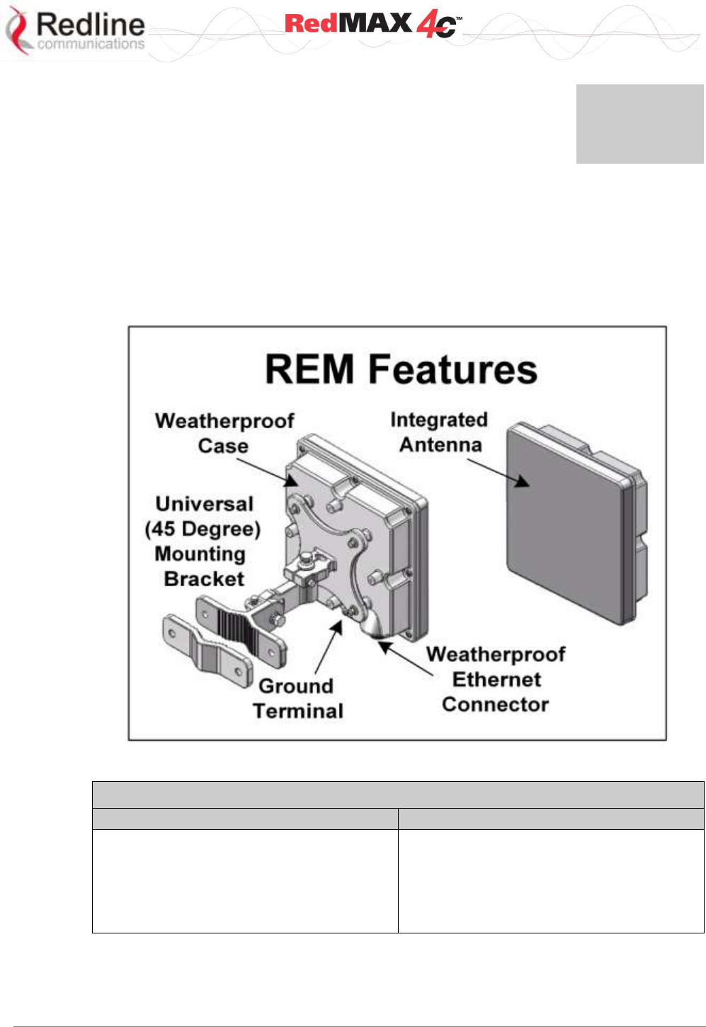
The subscriber is a fully integrated WiMAX Forum compliant subscriber device
incorporating a wireless modem interface to a remote WiMAX base station, and an
Ethernet interface for connection to the local network. The subscriber is a fully integrated
unit with a built-in Multiple Input/Multiple Output (MIMO) antenna system. Power is
supplied by Power Over Ethernet (PoE). The subscriber electronics are housed in a
weatherproof aluminum alloy case.
Figure 1: Subscriber System Features
Table 3: Subscriber Installation Parts
Included with system
Items sold separately
1. Subscriber with integrated antenna.
2. Power-over-Ethernet (PoE) power
adaptor.
3. Universal mounting bracket (assembly
required).
1. PoE power adapter AC power cord
(NA, UK, or EU).
2. Outdoor (ruggedized) Ethernet cable.
3. Lightning/surge protection.
User
REM Outdoor Subscriber Manual
70-00121-01-00 Proprietary Redline Communications © 2009 Page 14 of 34 October 20, 2009
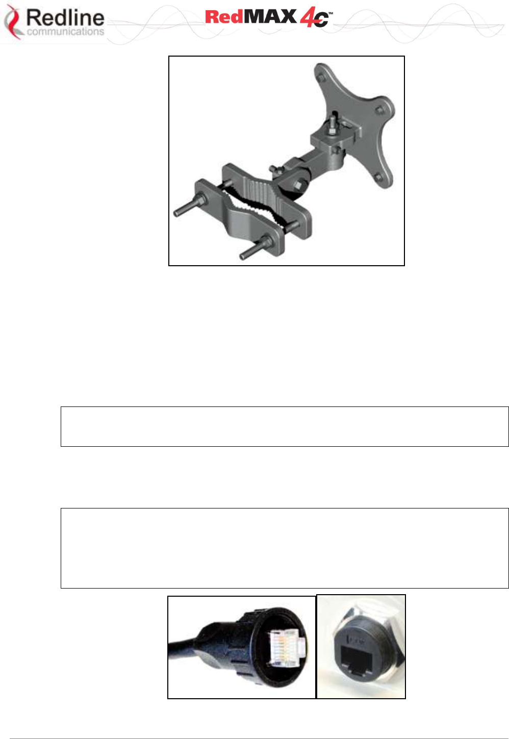
Figure 2: 90 Degree Universal Mounting Bracket
3.1.1 Ethernet Port (and Cable)
The auto-sensing 10/100Base-T Ethernet port connects through the outdoor Ethernet
cable to a PoE power adaptor/CO switch. The REM receives DC power and exchanges
data with the network through this port (straight-through connection).
The REM cable access entrance is equipped with a weatherproof seal. The outdoor end
of the Redline supplied outdoor (hardened) CAT-5 Ethernet cable is terminated with an
environmentally sealed RJ-45 connector for connection to the subscriber. The minimum
diameter to pass this connector through a conduit or hole is 26 mm (1 in).
Important: The PoE device is a passive Ethernet device and does not amplify or repeat
signal. The maximum total length of the Ethernet cable is 100 m (328 ft). For example, 98
m from the REM to the PoE and 2 m from the PoE to the connected network equipment.
The indoor end of the Redline supplied outdoor (hardened) CAT-5 Ethernet cable is
terminated with a standard indoor RJ-45 connector for connection to a PoE power
adaptor/CO switch. The minimum diameter to pass this connector through a conduit or
hole is 18 mm (11/16 in).
Important -- Warranty Information -- Ethernet Cable
Redline does not endorse or support the use of outdoor cable assemblies: i) not supplied by
Redline, ii) third-party products that do not meet Redline's cable and connector assembly
specifications, or iii) cables not installed and weatherproofed as specified in the Installation
Guidelines manual (70-00068-01-XX). Refer to the Redline Limited Standard Warranty and
RedCare service agreements.
Figure 3: Outdoor Ethernet Cable - Cable Connection
User
REM Outdoor Subscriber Manual
70-00121-01-00 Proprietary Redline Communications © 2009 Page 15 of 34 October 20, 2009
3.1.2 Grounding Connection
A ground terminal is located on the rear of the subscriber. Use this screw to terminate
the ground wires. Correct grounding is very important for safe operation of wireless
equipment. Ensure that all grounding connections are in accordance with local and
national standards.
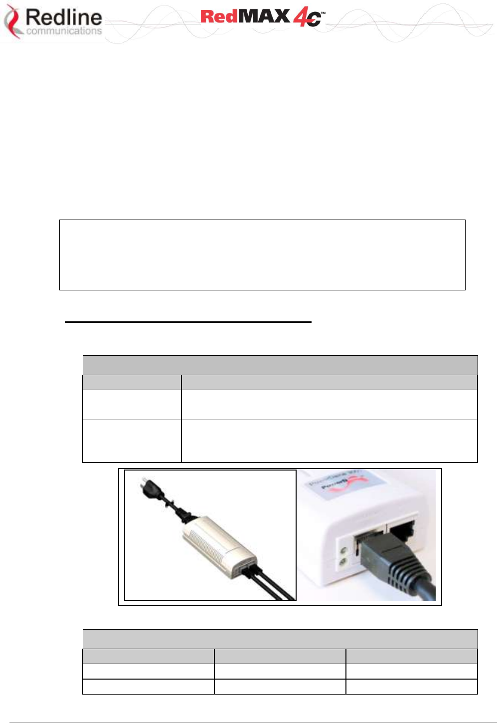
3.1.3 PoE (Power over Ethernet) Power Adaptor
The REM may be powered using a stand-alone PoE power adaptor, or by a central
office switch equipped with RJ-45 sockets that provide PoE power and data to the REM
device. All PoE devices must have metal-lined RJ-45 sockets that provide a protective
ground connection to the Ethernet cable shield. The PoE power adaptor may be
supplied by Redline as a stand-alone AC powered device.
<
Important -- PoE Equipment
The Ethernet outdoor cable is supplying a protective ground connection for the Ethernet
cable. Customer supplied PoE devices (e.g., central office switches equipped with RJ-45
sockets that provide PoE power and data) must have metal-lined RJ-45 sockets providing
a protective ground connection to the cable shield.
Redline Supplied PoE Power Adapter
The Redline supplied PoE power adaptor source is auto-sensing 110-240 (nominal)
VAC. The PoE power adaptor provides two Ethernet interfaces:
Table 4: System - PoE Ports
Port
Description
DATA IN
The auto-sensing 10/100Base-T Ethernet port (RJ-45
socket) for connection to the network equipment.
DATA & POWER
OUT
The auto-sensing 10/100Base-T Ethernet port (RJ-45
socket) port is used to carry signals and source power to
the outdoor subscriber outdoor unit.
Figure 4: Optional Redline-Supplied PoE Power Adaptor
Table 5: System - Ethernet Data Port Link/Act LEDs
LED
Port
Power Output
Solid
Connected
Power is active
Blink
Not connected
Out of range

User
REM Outdoor Subscriber Manual
70-00121-01-00 Proprietary Redline Communications © 2009 Page 16 of 34 October 20, 2009
Chapter
4
4
4
C
CL
LI
I
C
Co
om
mm
ma
an
nd
ds
s
The subscriber can be configured over a Telnet connection established through the subscriber
Ethernet port or the wireless interface from the base station. The CLI can not be used to setup
service flows.
Important: Access to the CLI commands is password protected. Only authorized installation and
service personnel are allowed access to these controls.
4.1 Local Ethernet Port IP
All factory-shipped subscriber systems have the following IP addresses assigned to the
local Ethernet port:
Fixed: 192.168.101.1 (can not be modified)
4.2 Telnet Access
4.2.1 Login
Type 'telnet' followed by the IP address of the subscriber system, depress ENTER, and
enter the account and password when prompted.
Username: admin
Password: admin
4.2.2 Logout
Exit from a CLI session by typing:
logout <ENTER>
The system prompts for logout confirmation. Depress 'Y' to complete the logout process.
Note: To exit from the Telnet session, you must be in the root directory. Go to the root
directory by typing: Exit <ENTER> or CTRL-Z (hold down the CTRL key and depress Z)
4.3 Modes and Commands
The subscriber CLI interface supports several modes of operation. The system defaults
to root mode when you login to the subscriber. From root mode you can display a list of
all user modes and commands, reboot the subscriber system, and logout from the Telnet
session. From all modes, you can directly display and modify (if applicable) each of the
parameters. Enter 'exit' or CTRL-Z to return to root mode. All commands are case-
sensitive.

User
REM Outdoor Subscriber Manual
70-00121-01-00 Proprietary Redline Communications © 2009 Page 17 of 34 October 20, 2009
Table 6: CLI - Generic Commands
Command
Description
?
Use the '?' character as an alternative to typing 'help <ENTER>'.
Example: Enter the following command string to list all parameters that can
be changed using the 'set' command:
set ?
set rfC ?
set rfConfig RxGain ?
tab
Use the tab character to auto-complete partially typed commands.
CTRL-Z
Return to root mode.
help
Type 'help' alone to display the available commands. Type a command
followed by 'help' to display a command set.
For example:
help <ENTER> Help for all functions/fields.
help command <ENTER>
help command parameter <ENTER>
Table 7: CLI - Modes and Commands
Command
Description
bsidtable
Access the Management Base Station ID table
buzzer
Audible alignment tool (if hardware equipped).
collectradio
Display radio statistics.
ethtag
Display/modify the Ethernet Tagging
eventlog
System event log.
interface
Configure Ethernet and wireless interfaces.
loadimage
Download and run a new software image
logout
Exit the current Telnet session.
realm
May be used by the ASN to select the AAA server.
reboot
Reset the system (confirmation required).
rfconfig
Display /modify the RF configuration
statistics
Statistics for authentication (EAP), Ethernet, and wireless interface.
status
Access the Management Status data structure
system
System software version settings
tr069
Communication between CPE and Auto Configuration Servers (ACS).

User
REM Outdoor Subscriber Manual
70-00121-01-00 Proprietary Redline Communications © 2009 Page 18 of 34 October 20, 2009
4.3.1 bsidtable - Base Station ID Table
The bsIdTable stores the MAC addresses of up to sixteen base stations. When one or
more MAC addresses are registered in the table, the subscriber is authorized to register
only with the listed base stations. When there are no entries in the bsIdTable table the
subscriber can register with any base station.
Table 8: CLI - bsIdTable - Base Station ID Table Commands
bsidtable <add> <delete> <show>
add <bsid> <priority> <0-15>
Add or replace a base station ID entry. If the table position value is not specified, the new
entry is inserted after the last valid entry. The table is filled from the beginning (position 0)
and positions are adjusted forward when 'empty' entries are not permitted. The count
value is adjusted to the current number of entries.
bsid <aa:bb:cc:dd:ee:ff>
Enter base station MAC address.
priority <<0-7>
Enter priority for this base station. When multiple base stations are detected, the CPE
will attempt to register entry having the highest priority (7).
<0-15>
Entry position in the table (optional).
Example: Use the following command to register a base station with priority 2 in the
fourth position in the table:
CPE(bsId ->)# add 00:09:02:00:a3:5d priority 2 3 <Enter>
delete <entrynumber> <all | yestoall>
Delete a base station ID entry. If the table position value is not specified, the last entry in
the table is deleted. The count value is adjusted to reflect the current number of entries.
Confirmation is required.
<0-15>
Identify the specific entry position in the table (first entry is zero).
Example: Enter the following command to delete the 3rd entry in the table:
CPE(bsId ->)# delete 2 <Enter>
Are you sure ? Enter Y to delete this entry
all
Delete all entries in the table. Operator confirmation is required.
yestoall
Delete all entries in the table. Confirmation is not required.
show <0-15>
Display the base station ID table entries.
<0-15>
Identify the specific entry position in the table. If the table position is not specified, all
entries in the table are displayed.
count
Display only the number of active entries in the table.
bsidentrie
Display only the base station ID values and associated priorities.
Note: The following actions are taken when the bsidtable is modified:
1. A 'Detected BS table reset' log message is generated.
2. An 'Add/Delete detected BS…' log message is generated if a new entry has been added.
3. A frequency scan is initiated.

User
REM Outdoor Subscriber Manual
70-00121-01-00 Proprietary Redline Communications © 2009 Page 19 of 34 October 20, 2009
4.3.2 buzzer - Antenna alignment Tool
Audible alignment tool (if hardware equipped).
Table 9: CLI - buzzer - Antenna Alignment Tool Commands
buzzer <set> <show>
Enable and disable audible alignment tool and show current status. This feature is supported
only on outdoors models.
set <0 | 1>
Enable and disable audible alignment tool.
0 - Disable buzzer.
1 - Enable buzzer
show
Display status of audible alignment tool.
Buzzer is turned off.
Buzzer is turned on.
Buzzer is not present on this platform.
4.3.3 collectradio - Radio Statistics
Collect and display information about the radio.
Important: This command produces machine-readable output only.
Table 10: CLI - collectradio - Radio Statistics
collectradio <get> <time>
Specify radio collection parameters.
get
Displays the radio statistics (no parameters).
For example:
CPE(collectRadio ->)#>get
Press any key to exit ...
♥0.0☺♥0.0☻☺0♥-79.0♦☺0♥0.0☺♥0.0☻☺0 ...
End of collecting data
time <50 - 10000>
Change or display the current data output rate (ms).

User
REM Outdoor Subscriber Manual
70-00121-01-00 Proprietary Redline Communications © 2009 Page 20 of 34 October 20, 2009
4.3.4 ethtag - Ethernet Tagging
Use 802.1Q VLAN tags to identify data traffic through the subscriber.
Table 11: CLI - ethTag - Ethernet Tagging Commands
ethertag <reset> <set> <show>
View and adjust the VLAN tag settings.
reset <yes>
Set all tagging parameters to factory default values (Active=Priority=Value=0). Requires
operator confirmation if 'yes' is not specified.
yes - Do not ask operator for confirmation.
set <active> <priority> <value>
Change Ethernet VLAN tagging parameters.
active <0- | 1>
Set the tagging mode.
0: Disabled - All tagging features are disabled.
1: Enabled - Each upstream packet received on the subscriber Ethernet port is tagged
with the specified VID (value field). If the packet has an existing VLAN tag, a new
outermost tag is added (Q in Q). The modified packet is forwarded over the wireless
interface to the base station.
priority <0-7>
Default priority for VLAN tagged packets.
value <VLAN ID>
This is the VLAN tag added to all uplink packets (when tagging is enabled).
show <active> <priority> <value> <monitor>
Display the current settings.
active
Display the active/inactive state for the tagging feature.
priority
Display the priority assigned to added VLAN tagged packets.
value
Display the VLAN ID.
monitor
Continuously display the mode (active), priority, and VLAN ID (value) fields. Press any
key to stop updates.

User
REM Outdoor Subscriber Manual
70-00121-01-00 Proprietary Redline Communications © 2009 Page 21 of 34 October 20, 2009
4.3.5 interface - Ethernet Port and Wireless Settings
Use the interface command to view and configure the Ethernet ports.
Table 12: CLI - interface - Ethernet and Wireless Configuration Commands
interface <eth0> <wman0>
Ethernet port settings.
eth0 <set> <show>
set <ip> <port>
View and adjust the Ethernet port speed, duplex, and IP settings.
ip <address> <mask> <yes>
View/modify the Ethernet (management) IP address.
address <aaa.bbb.ccc.ddd>
Set CPE IP address. Requires operator confirmation.
mask <aaa.bbb.ccc.ddd>
Set CPE network mask for CPE. Requires operator confirmation.
yes
Enter 'yes' to override request for operator confirmation.
Example: Use the following command to set a static IP address and mask and
not ask for confirmation:
CPE# interfaces eth0
CPE(itf:eth0)# set ip address 192.168.20.33 mask 255.255.255.0 yes
port <auto> <duplex> <speed>
Ethernet port settings.
auto <0 | 1>
Set negotiation mode.
0: Disable auto-detect speed and duplex. See speed and duplex.
1: Enable auto-detect speed and duplex. Ignore speed and duplex.
duplex <0 | 1>
Set Ethernet port duplex.
0: Operate at half duplex mode only.
1: Operate at full duplex mode only.
speed <0 | 1>
Set Ethernet port speed.
0: Operate at 10Base-T only.
1: Operate at 100Base-T only.
show <ip> <port>
Display current settings.
Example: Enter the following command to display the Ethernet port ip settings:
CPE# interface ethernet show ip
Settings --- <<SS IP Address Data>>
Address= 10.1.1.254
Mask= 255.255.255.0
wman0 <set> <show>
Wireless interface settings. Changes to these values are effective only following a reboot.
set <configcapabilities> <csublayer> <phy>
View and modify the wireless interface settings. The subscriber uses a 5 ms frame
duration only with a cyclic prefix of 1/8. Bandwidth setting determines the FFT size.
configcapabilities <authpolicysupport> <openloopsupport>
View and modify the wireless interface authentication settings.
authpolicysupport <0 | 1>

User
REM Outdoor Subscriber Manual
70-00121-01-00 Proprietary Redline Communications © 2009 Page 22 of 34 October 20, 2009
Table 12: CLI - interface - Ethernet and Wireless Configuration Commands
Set Authorization Policy mode.
0 - Disabled: No authentication.
1 - Enabled: Authentication is required.
openloopsupport <0 | 1>
Subscriber terminal adjusts transmission level based on the signal strength
measured on the preamble received from the base station.
0 - Disabled: Subscriber does not use open loop control.
1 - Enabled: Open loop control is active.
csublayer <0-2>
View and modify the wireless interface convergence sublayer settings.
0 - IPCS+NAT
1 - EthernetCS
2 - IPCS
phy <bandwidth> <framesize >
View and modify the wireless interface physical layer settings.
bandwidth <5000 | 7000 | 8750 | 10000>
Channel size (Hz).
5000 - 5 MHZ
7000 - 7 MHZ*
8750 - 8.75 MHZ*
10000 - 10 MHZ
framesize <5000 | 10000>
Frame duration (microseconds).
5000 - 5,000 us
10000 - 10,000 us
Show <configCapabilities> <csublayer> <phy>
Display the wireless configuration.
For example:
CPE(itf:wman0)# show phy
Settings -- <<SS Mmgt PHY Configuration Parameter>>
Bandwidth= 7000 kHz
FftSize= 1024
CyclicPrefix= 8 PS
FrameSize= 5000 us
Note: The bandwidth setting controls the FFT size and cyclic prefix.
* Not supported by 1.8 GHz CPE.

User
REM Outdoor Subscriber Manual
70-00121-01-00 Proprietary Redline Communications © 2009 Page 23 of 34 October 20, 2009
4.3.6 loadImage - Download and Activate Software Image
Use the loadImage command to update the subscriber over-the-air or using the local
Ethernet connection. The following items must be addressed before beginning software
upgrades:
1. All software upgrades use an FTP server.
2. The FTP server must have a user account with the following settings:
Username: target
Password: secret
3. The subscriber binary file must be copied to the default file location for this user
account on the FTP server.
Table 13: CLI - loadImage - Upgrade CPE Software Commands
loadImage
Load new subscriber software image. This command does not accept any parameters. The
command will prompt for the following information:
ServerIP
IP address of FTP server.
Filename
Name of the binary file. Must be located in the FTP default directory.
Example:
CPE#> loadImage
Server IP Address: 192.168.100.100
File Name: REM-18-M-001-02-02-005.bin
Opening FTP connection.....Done
Downloading image
............................................................................................………………
Done
Programming update........Done
Erasing setup partition. Done.
Writing setup partition. Done.
Erasing boot block. Done
Programming boot block. Done
Flash programming complete.
CPE#><enter reboot command to load new software>
4.3.7 realm - Domain Reference for Locating AAA Server
May be used by the ASN to select the AAA server.
Table 14: CLI - realm - For Locating AAA Server Commands
realm <set> <show>
Set parameters to factory default values. If no parameter is specified.
configuration <backup> <restore>
Use an FTP server to save and restore the subscriber configuration.
set <domain.name>
Enter a new realm domain.
Example:
CPE# realm tier1.com
show
Display current realm.

User
REM Outdoor Subscriber Manual
70-00121-01-00 Proprietary Redline Communications © 2009 Page 24 of 34 October 20, 2009
4.3.8 rfConfig - Configure RF Settings
The rfConfig mode allows you to view and modify the subscriber RF settings.
Note: The subscriber must be rebooted before changes to the rfConfig frequency
settings become effective.
Table 15: CLI - rfConfig - RF Configuration Commands
rfConfig <reset> <set> <show>
View and modify the subscriber RF settings.
reset <yes>
Reset all RF parameters to factory default values. Requires confirmation.
yes
Append yes to command to override operator confirmation.
set <param1><value1> ... <paramn><valuen>
View and modify the RF parameters.
freqpriorityn <0-9>
Priority for this frequency interval (n=1-16).
hirffreqn <1800 - 1830 >
High frequency (KHz) for this frequency interval (n=1-16).
Example:
CPE# rfconfig set hirffreq1 1810000
lorffreqn <1800 - 1830>
High frequency (KHz) for this frequency interval (n=1-16).
maxrngretries <1 - 5000>
Max number of retries for initial ranging.
maxtxpower <value>
Maximum Tx power (dBm). Refer to specifications.
nomadic <0 |1>
Set the nomadic mode.
0 -- Disable
1 -- Enable
rxagc <0 | 1>
Receive automatic gain control (AGC).
0 - Disable AGC.
1 - Enable AGC.
rxgain <-19.00 to 80.00>
Enter the Rx Gain value (dB). This may be a decimal number.
stickinesstimer <1-120>
Time (seconds) to attempt re-connection to the same base station.
txactualpower <value>
Actual Tx power (dB). Refer to specifications.
txfixedgain <0|1>
Tx power scan during network entry.
0 - Enable
1 - Disable
txfixedpower <value>
Transmitter gain value (dB). This may be a decimal number.

User
REM Outdoor Subscriber Manual
70-00121-01-00 Proprietary Redline Communications © 2009 Page 25 of 34 October 20, 2009
Table 15: CLI - rfConfig - RF Configuration Commands
show <parameter1> ... <parametern>
Show the current parameter settings. Displays the set commands above and the following:
rxfreq
Current receiver frequency (KHz).
rftemp
Radio temperature (Celsius).
rxrfrssi
Received RSSI.
rxlock
Receiver lock mode.
0 - Disabled.
1 - Enabled.
txlock
Transmitter lock mode.
0 - Disabled.
1 - Enabled.
Notes:
1. When specifying a single channel, enter the RF frequency in the 'hirffreqn' setting
and then enter the identical value in the 'lorffreqn' setting.
2. Scanning ranges must not intersect or overlap.
3. When changing settings, the order of data entry must ensure the 'hirffreqn' setting is
always greater than the 'lorffreqn' setting. For example, when changing from the
default setting (hirffreqn=lorffreqn=0) you must enter the hirffreqn setting first.
Frequency Scanning
Frequency scanning is performed in 250 KHz steps, monitoring each step for
approximately four seconds. The subscriber will always complete the entire scan for all
non-zero ranges. If all ranges are zero, the subscriber will scan the entire range of the
radio. During the scan, the subscriber compiles a table of detected base stations (filtered
by the bsidtable entries) and orders the results based on priority and then signal level
(CINR). Once the scan is completed, the table is saved in non-volatile RAM (preserved
through subscriber reboot/power-cycle).
A frequency scan is triggered by any of the following events:
1. The RF parameters are modified.
2. The bsidtable (allowed base station list) is modified.
3. There are no base stations in the scanning results table.
Following any of the events listed above, the subscriber attempts to register with the first
base station in the scanning results table. If the subscriber is unable to register with a
base station, that entry is removed from the scanning results table. Once registered, the
subscriber remains connected to that base station. If the connection to the base station
is lost while the subscriber is online (e.g., base station rebooted), that base station is
removed from the scanning results table, and the subscriber attempts to register with the
next base station in the scanning results table. If the scanning results table becomes
empty, the scanning process is restarted.

User
REM Outdoor Subscriber Manual
70-00121-01-00 Proprietary Redline Communications © 2009 Page 26 of 34 October 20, 2009
4.3.9 statistics - Display Statistics
The statistics mode allows you to view subscriber operational statistics.
Table 16: CLI - statistics - Statistics Commands
statistics <eap> <interface> <packetFlows>
Subscriber operational statistics.
eap <reset><show>
Display EAP-based statistics.
reset
Reset all counters to zero.
show
Display current statistics values.
CPE#>statistics eap show
inPackets = 0
outPackets = 0
eapStart = 0
eapIdRequest = 0
eapIdReply = 0
eapSuccess = 0
eapFail = 0
ineapTlsPackets = 0
outeapTlsPackets = 0
outeapAuthKeys = 0
badeapAuthKeys = 0
eaplastidxReq = 0
forwarder <show>
Packet forwarder statistics.
show
Display packet forwarder statistics.
CPE#>statistics forwarder show
FORWARDER SYNTHESIS
==================================================
Interface | Packets Loss (unit=packet)
====================TO INTERFACE==================
RF-RX | 0
--------------------------------------------------
Local-RX | 2567
--------------------------------------------------
Etm-RX | 2597
===================FROM INTERFACE=================
RF-TX | 0
--------------------------------------------------
Local-TX | 2581
--------------------------------------------------
Etm-TX | 2581 Dropped=30
interface <eth0> <wman>
Display Ethernet or wireless statistics.
eth0 <clear><show>
Ethernet statistics.
clear
Reset all counters to zero.

User
REM Outdoor Subscriber Manual
70-00121-01-00 Proprietary Redline Communications © 2009 Page 27 of 34 October 20, 2009
Table 16: CLI - statistics - Statistics Commands
show
Display current statistics values.
CPE #>statistics interface eth0 show
Settings --- <<Ethernet Statistics>>
InPacket= 2500
InBytes= 0
OutPacket= 2461
OutBytes= 0
wman0 <show>
Wireless interface statistics.
clear
Reset all counters to zero.
show
Display current statistics values.
CPE#>statistics interface wman0 show
Settings --- <<Wman statistics>>
InPacket= 0
InBytes= 0
OutPacket= 0
OutBytes= 0
packetflows <show>
Packet-based statistics.
show
Display current statistics values.
CPE#>statistics packetflows show
PACKET FLOW SYNTHESIS
==================================================
Module | Input Output Loss (unit=packet)
=======================UPLINK=====================
ETM-RX | 2649 2649
--------------------------------------------------
DMC | 0 0
UQSS | 0 0
UMSS | 0 0
======================DOWNLINK====================
RTM | 0 0
--------------------------------------------------
ETM-TX | 2648 2648

User
REM Outdoor Subscriber Manual
70-00121-01-00 Proprietary Redline Communications © 2009 Page 28 of 34 October 20, 2009
4.3.10 status - Display Status Information
Use status mode to view subscriber status information.
Table 17: CLI - status - Status Commands
status <show>
display subscriber status information.
show <parameter1> ... <parametern>
display specified parameter(s). if no parameters are specified, display all values.
cinr carrier/(interference + noise)
dcd show downlink channel descriptor group of statistics
dcdchangecount current downlink channel descriptor count used by the mac
dcdcrccount downlink channel descriptor crc errors
dcderrcount downlink channel descriptor semantic errors
dcdrxcount downlink channel descriptor s parsed
dlbytecount downlink data bytes received
dlcrcerrcount downlink data crc errors
dlfpcount downlink fps received (to frames)
dlfpcrccount downlink fp semantic errors
dlfperrcount downlink fp semantic errors
dlhcrcerrcount downlink data hcrc errors
dlmapcount downlink maps parsed
dlmapcrccount downlink map crc errors
dlmaperrcount downlink map semantic errors
dlmpducount downlink MAC packet data units sent received
dlsducount downlink MAC service data units received
downlink show all fields of downlink group
frameduration Frame duration in microseconds
freqoffset frequency offset
linkstatus 0 -- non-registered, 1 -- registered
lostframes logical frames lost
manage show all fields of management group
mgmtcrccount management message crc errors
mgmterrcount management message semantic errors
mgmtrxcount other management messages parsed
modemresets modem reset due to errors
monitor enter into monitor mode, press any key to exit
other show all fields not belonging to a specific group
rfrssi received signal strength indication (at phy)
rngtimecorrection time correction resulting from RNG response
rssi received signal strength indicator
snr signal to noise ratio
tcnt time count of the last received burst
totalbwreqcount bandwidth requests sent
totalcrcerrors payload crc errors
totalhcrcerrors header crc errors
totalmgmsentcount other management messages sent
totalpaddingcount padding MAC packet data units sent
totalrngreqcount ranging requests sent (including initial)
totaltxburstcount bursts transmitted
txactualpower transmit actual power

User
REM Outdoor Subscriber Manual
70-00121-01-00 Proprietary Redline Communications © 2009 Page 29 of 34 October 20, 2009
Table 17: CLI - status - Status Commands
ucd show ucd group of statistics
ucdcrccount ucd crc errors
ucderrcount ucd semantic errors
ucdrxcount ucds parsed
ulbytecount ul data bytes sent
ulmapcount ulmaps parsed
ulmapcrccount ulmap crc errors
ulmaperrcount ulmap semantic errors
ulmpducount ul mpdus sent
ulsducount ul sdus sent
uplink show uplink group of statistics
4.3.11 system - Subscriber General Configuration
Use the system commands to display the software versions stored in the subscriber non-
volatile memory, download software updates, and switch the active versions.
Table 18: CLI - system - System Commands
system <configuration> <reboot> <show> <software> <summary>
Set parameters to factory default values. If no parameter is specified.
configuration <backup> <restore>
Use an FTP server to save and restore the subscriber configuration.
backup <server> <file>
Save the subscriber configuration on a TFTP server.
server <IP Address>
IP address of TFTP server.
file <string>
Name of the binary file. Must be located in the TFTP default directory.
restore <server> <file>
Restore the subscriber settings from a saved configuration file.
server <IP Address>
IP address of TFTP server.
file <string>
Name of the binary file. Must be located in the TFTP default directory.
reboot <yes>
Reboot the subscriber (confirmation required).
yes
Perform operation without operator confirmation.
Example:
CPE#system reboot yes
show <swver>
Display system settings.
swver
Display current software version.
Example: Enter the following command to display version:
CPE# system show swver
Active Software Image= 2.2.5
Passive Software Image= 2.2.4

User
REM Outdoor Subscriber Manual
70-00121-01-00 Proprietary Redline Communications © 2009 Page 30 of 34 October 20, 2009
Table 18: CLI - system - System Commands
software <download> <switch> <switch_and_reboot>
Download new software to the subscriber.
download <server> < file>
Download subscriber software from TFTP server.
server <aaa.bbb.ccc.ddd>
TFTP server IP address
file <finename.bin>
Software binary file name.
switch <yes>
Change to alternate software. Operator confirmation is required.
yes
Perform operation without operator confirmation.
Example:
CPE#system switch yes
switch_and_reboot <yes>
Change to alternate software and reboot CPE. Operator confirmation is required).
yes
Perform operation without operator confirmation.
summary
Display summary information.
CPE# system summary
Redline Communications Inc.
REM
Active Software Image= 2.2.5
Passive Software Image= 2.2.4
4.3.12 tr069 - Auto Configuration Servers Support
Communication between CPE and Auto Configuration Servers (ACS).
Table 19: CLI - tr069 - Auto Configuration Servers Support Commands
tr069 <set> <show>
Set parameters to factory default values. If no parameter is specified.
configuration <backup> <restore>
Use an FTP server to save and restore the subscriber configuration.
set <enable>
Enable and disable tr069 mode.
enable <0 | 1>
Set tr069 mode.
0 - Disable tr069.
1 - Enable tr069.
show
Display current tr069mode.

User
REM Outdoor Subscriber Manual
70-00121-01-00 Proprietary Redline Communications © 2009 Page 31 of 34 October 20, 2009
Chapter
5
5
5
A
Ap
pp
pe
en
nd
di
ic
ce
es
s
5.1 System Technical Specifications
<
Table 20: Specifications - Indoor Wireless Subscriber Modem
System Models: REM2500M: 2.496 - 2.69 GHz
Mobile WiMAX modem compliant with WiMAX Certification
Wave 2: Profile 3A: 2.5-2.7 GHz, 5/10 MHz, TDD
REM3500M: 3.4 - 3.6 GHz
Mobile WiMAX modem compliant with WiMAX Certification
Wave 2: Profile 5A: 3.4-3.6 GHz, 5/7/10 MHz, TDD
Physical Layer: Scalable OFDMA (512/1024 FFT)
MIMO support (Matrix A/Space Time Coding and Matrix B/Spatial
Multiplexing) Supports 2x2 downlink MIMO and Collaborative
uplink MIMO operation
MAC Attributes: Hybrid ARQ with convolutional turbo codes (CTC)
QoS: Best Effort (BE), non Real TIme Polling Service (nrtPS), Real
Time Polling Service (rtPS), Extended Real Time Polling Service
(ertPS), Unsolicited Grant Service (UGS)
Duplex Technique: TDD (time division duplex)
Tx Power: Up to 26.66 dBm
Rx Sensitivity: 3 dB better than MRCT
Network Attributes: Transparent bridge 802.1p, 802.1Q VLAN port tagging, 802.1Q,
TOS/DSCP and L2/L3 address, traffic classification
Modulation: QPSK, 16 QAM, 64 QAM
Forward Error Correction: Convolutional Turbo Coder/Decoder
Over the Air Encryption: AES
Network Connections: 10/100 Ethernet (RJ-45)
System Configuration: SNMP, FTP
Network Management: SNMP, standard and proprietary MIBs. Full management by
Redline Management Suite (RMS)
PoE Power Injector: Standard IEEE 802.3af (15.4 W Max.)
Input: Auto-sensing 110-250 VAC 50/60 Hz, 0.5 A
Output: 48 V, 0.35A
Dimensions: 5.5” x 2.25” x 1"
Compliance: EMC: EN 301 489-1, EN 301 489-4, EN 550 24
EN 55022/CISPR 22
RF: EN 302 544 (2.496 - 2.69 GHz)
EN 302 326 (3.4 - 3.6 GHz)
Safety: IEC 60950-1, EN 60950-1
Enclosure Protection: IEC 60529 (IP 67)
Operating Temperature: -40 C to 60 C (-40 to 140 F)
Storage: 5 - 70 C (40 - 160 F), 5 - 95% Humidity
Wind Loading: Antenna: 220 Km/hr (137 mph)
Dimensions: 20 x 20 x 7.5 cm (8 x 8 x 2.5 in)
Weight: 1.8 Kg (4 lb) (does not include mounting bracket)
Antenna: Two cross polarized integrated antennas (14 dBi gain)
Power Consumption: 5 W Maximum

User
REM Outdoor Subscriber Manual
70-00121-01-00 Proprietary Redline Communications © 2009 Page 32 of 34 October 20, 2009
5.2 Subscriber Upgrade Procedure
Before Beginning the Upgrade
Use the following procedures to upgrade the subscriber.
The following items must be addressed before beginning the upgrade:
1. You must obtain the latest subscriber binary files.
2. The subscriber performs all software upgrades using an FTP server:
a) The FTP server must be located on the network connected to the subscriber
Ethernet port, or be reachable over the air interface.
b) The FTP server must have a user account defined as follows:
username: target
password: secret
c) You must copy the subscriber binary file into the default file location for the FTP
account (not able to specify a pathname in the upgrade dialog).
Update Software Procedure
Start a telnet session to the subscriber using the following settings:
Login: admin
Password: admin
Enter the 'loadImage' command. The subscriber will prompt you to enter the following
information:
Server IP address: [enter address of FTP server]
File Name: [enter base station binary file name]
The subscriber performs FTP server authentication with user name 'target' and password
'secret' (these settings cannot be altered). The image will be uploaded to the subscriber
and saved in the non-volatile memory (flash).
The subscriber must be reset to load the new software. Enter the 'reboot' command to reset the
unit. The telnet session will be terminated.
Example Download Dialog with Subscriber
Login: admin
Password:
admin, welcome to the SS CLI.
SUI#> loadImage
Server IP Address: [enter ftp server IP address here]
File Name: [enter binary file name here]
Opening FTP connection.....Done
Downloading image
............................................................................................………………
Done
Programming update........Done
Erasing setup partition. Done.
Writing setup partition. Done.
Erasing boot block. Done
Programming boot block. Done
Flash programming complete.
SUI#>reboot

User
REM Outdoor Subscriber Manual
70-00121-01-00 Proprietary Redline Communications © 2009 Page 33 of 34 October 20, 2009

70-00121-01-00 Proprietary Redline Communications © 2009 Page 34 of 34 October 20, 2009
302 Town Centre Suite 100 Markham, Ontario Canada L3R 0E8
www.redlinecommunications.com