Redline Communications SUOA RedMAX SU-O User Manual 70 00057 01 01 DRAFT
Redline Communications Inc. RedMAX SU-O 70 00057 01 01 DRAFT
UserManual.wiki
>
Redline Communications
>
SUOA User Manual
User Manual
Navigation menu
Upload a User Manual
Namespaces
Wiki Guide
HTML
PDF
Info
Views
User Manual
Discussion / Help
Navigation

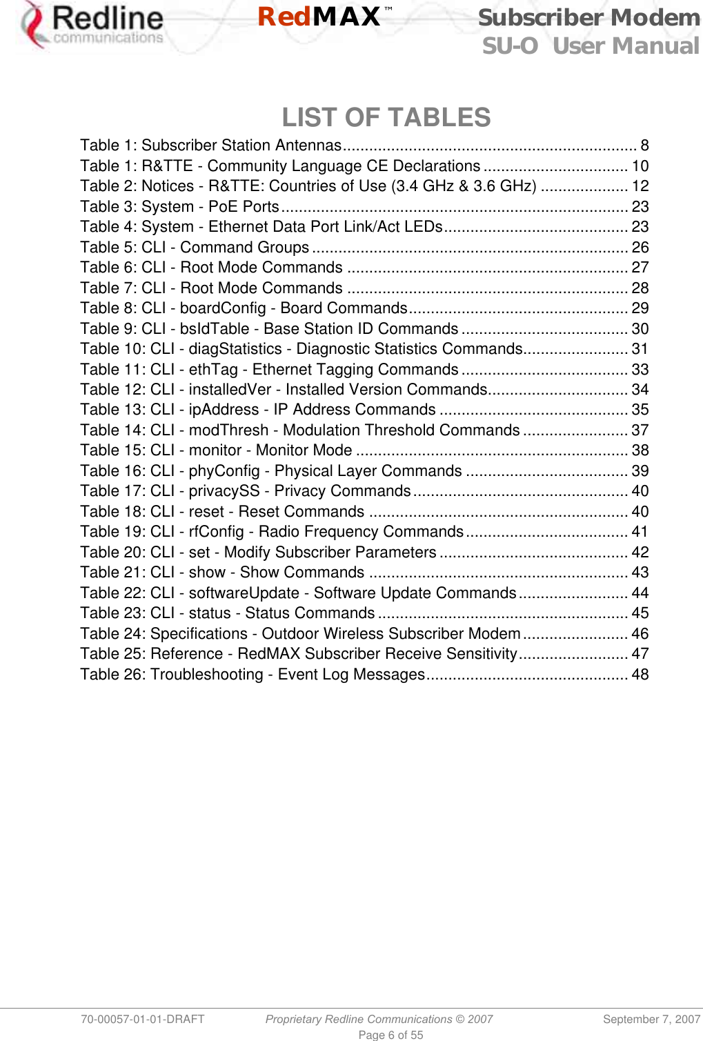
![RedMAX™ Subscriber Modem SU-O User Manual 70-00057-01-01-DRAFT Proprietary Redline Communications © 2007 September 7, 2007 Page 26 of 55 Chapter 4 44 CCLLII CCoommmmaannddss This section describes the subscriber CLI commands. Important: Access to these commands is password protected. Only authorized professional installation and service personnel are allowed access to these controls. 4.1 Introduction The subscriber can be configured using a Telnet connection established through the subscriber Ethernet port or over the wireless interface from the base station. The CLI can not be used to setup service flows. All service flows will be setup by the base station. 4.2 CLI Modes The subscriber CLI interface supports several modes of operation. From root mode you can display a list of all user modes, reboot the subscriber system, and logout from the Telnet session. Monitor mode provides a dynamic display of the current system statistics, updated each few seconds. Configuration modes allow you to view and adjust the subscriber network and wireless settings. 4.2.1 Telnet Connection Telnet Login Type 'telnet' followed by the IP address of the subscriber system, depress ENTER, and enter the account and password when prompted. The subscriber supports two separate user accounts: Table 5: CLI - Command Groups Account Password Description admin admin Full system control user2 user2 Read-only with some functional restrictions (not allowed to use the 'set' command). guest guest Same as user2. Telnet Logout To exit from the Telnet session, you must be in the root directory. Go to the root directory by typing: Exit [ENTER] or CTRL-Z (hold down the CTRL key and depress Z) Exit from a CLI session by typing: logout [ENTER] The system prompts for logout confirmation. Depress 'Y' to complete the logout process.](https://usermanual.wiki/Redline-Communications/SUOA/User-Guide-840520-Page-26.png)
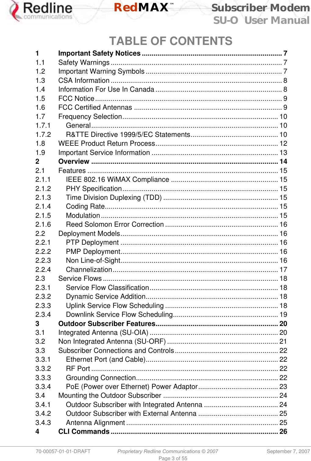
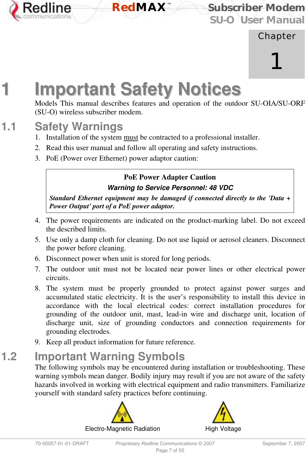
![RedMAX™ Subscriber Modem SU-O User Manual 70-00057-01-01-DRAFT Proprietary Redline Communications © 2007 September 7, 2007 Page 27 of 55 The system displays a welcome message when successfully logged in. Figure 12: Subscriber CLI Interface - Login Dialog Login: admin Password: admin SUO#> 4.2.2 Root Commands The following CLI commands are common to all configuration modes. Table 6: CLI - Root Mode Commands Command Description ? Use the '?' character as an alternative to typing 'help <ENTER>'. Example: Enter the following command string to list all parameters that can be changed using the 'set' command: set ? Exit Return to root mode. help Type 'help' alone to display the available commands. Type a command followed by 'help' to display a command set. help <ENTER> Help for all functions/fields. [field] help <ENTER> Help for only the selected function/field. logout Exit the current Telnet session. collectRadio Factory test only. reboot Reset the system. Confirmation is required. shell Factory test only. CTRL-Z Return to root mode.](https://usermanual.wiki/Redline-Communications/SUOA/User-Guide-840520-Page-27.png)
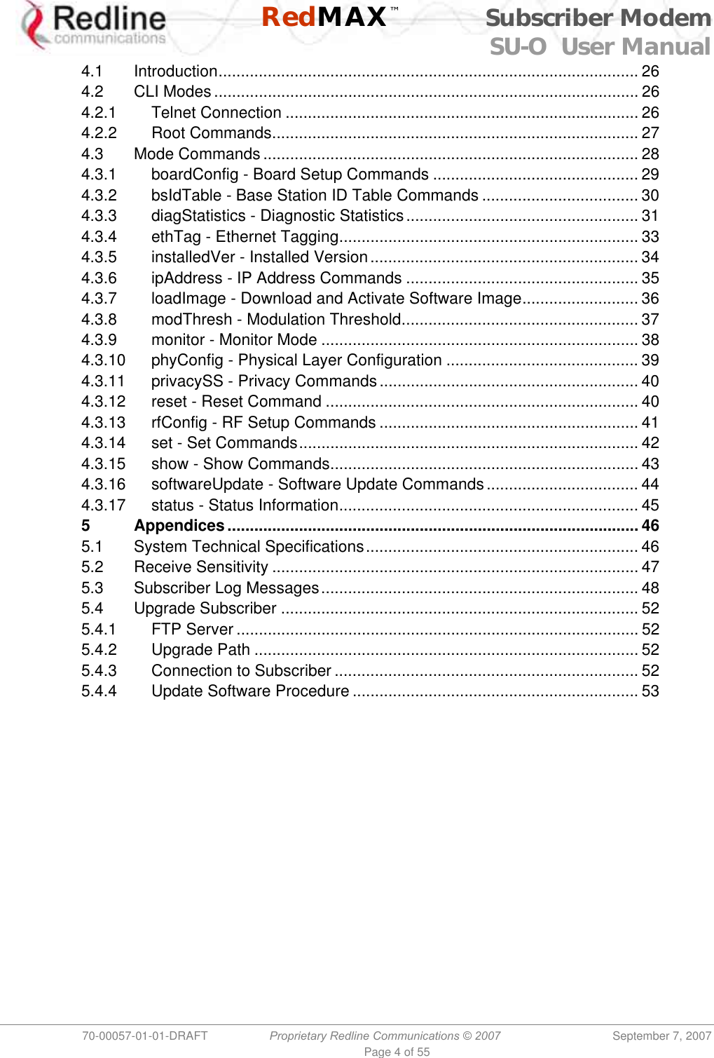
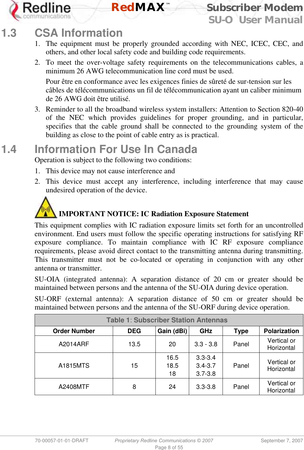
![RedMAX™ Subscriber Modem SU-O User Manual 70-00057-01-01-DRAFT Proprietary Redline Communications © 2007 September 7, 2007 Page 30 of 55 4.3.2 bsIdTable - Base Station ID Table Commands The bsIdTable includes the MAC addresses of up to sixteen base stations. The subscriber is authorized to register with any base station listed in this table. The count value indicates the number of valid entries in the table (beginning at ID0). When the subscriber is performing a frequency scan, the scan will be stopped immediately if any base station listed in the bsIdTable is detected. If subscriber is attempting to re-register, selection priority is based on table position (ID0 is highest). Table 9: CLI - bsIdTable - Base Station ID Commands Command Description add Add or modify a base station ID entry. The count value will be adjusted to reflect the current number of effective entries. If the table position value is not specified, the entry will be made following the last valid entry. BsId: The new entry of BsId value EntryNumber: The entry position in the table. Example: Enter the following command string to register a base station ID in table position #7: add 00:09:02:00:a3:5d [Enter] delete Delete a base station ID entry. The count value will be adjusted to reflect the current number of effective entries. If the table position value is not specified, the last valid entry in the table is deleted. EntryNumber: The entry position in the table. show Display the base station ID table entries. If the table position value is not specified, all entries in the table are displayed. If the keyword 'monitor' is used, the display is updated continually. EntryNumber: The entry position in the table. Monitor: Dynamically updated display of table values. Notes: 1. The detected BS table is automatically reset at the first restart after either the frequency range table, the BS ID table or the bandwidth is modified. 2. New “Detected BS table reset” log message generated when any of the modifications described above occur. 3. New “Add detected BS…” log message added any time a new BS is added to the table during the initial scan process.](https://usermanual.wiki/Redline-Communications/SUOA/User-Guide-840520-Page-30.png)

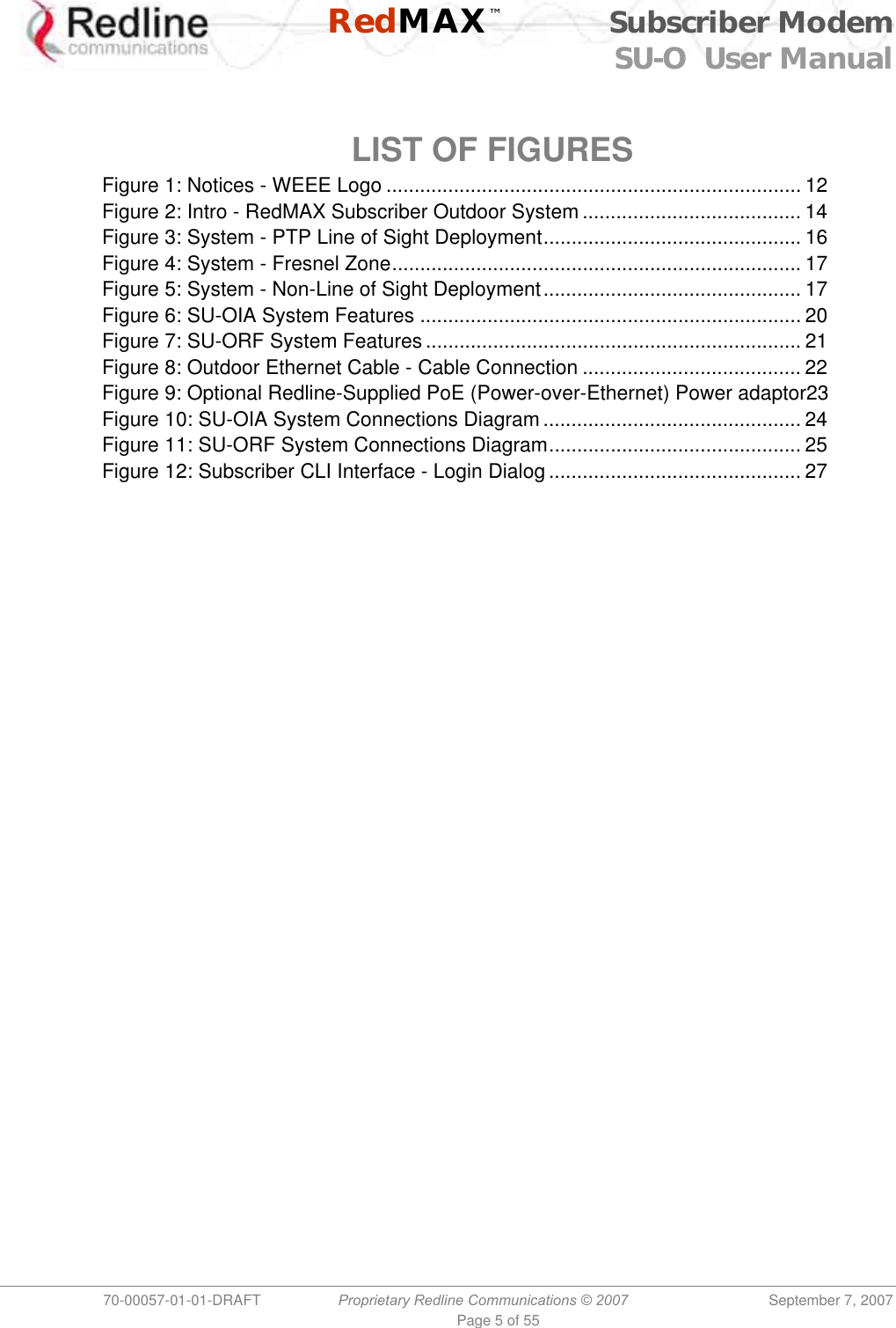
![RedMAX™ Subscriber Modem SU-O User Manual 70-00057-01-01-DRAFT Proprietary Redline Communications © 2007 September 7, 2007 Page 36 of 55 4.3.7 loadImage - Download and Activate Software Image The loadImage command can be used to update the subscriber using the SMC channel over-the-air or the local Ethernet connection at the subscriber. The following provides and example update session. The subscriber will reboot using the new image automatically following a successful download. Example Download Dialog with Subscriber Login: admin Password: admin, welcome to the SS CLI. (Version 0.3) SUO#> loadImage Server IP Address: [enter ftp server IP address here] File Name: [enter binary file name here] Opening FTP connection.....Done Downloading image ............................................................................................……………… Done Programming update........Done Erasing setup partition. Done. Writing setup partition. Done. Erasing boot block. Done Programming boot block. Done Flash programming complete. SUO#>reboot](https://usermanual.wiki/Redline-Communications/SUOA/User-Guide-840520-Page-36.png)
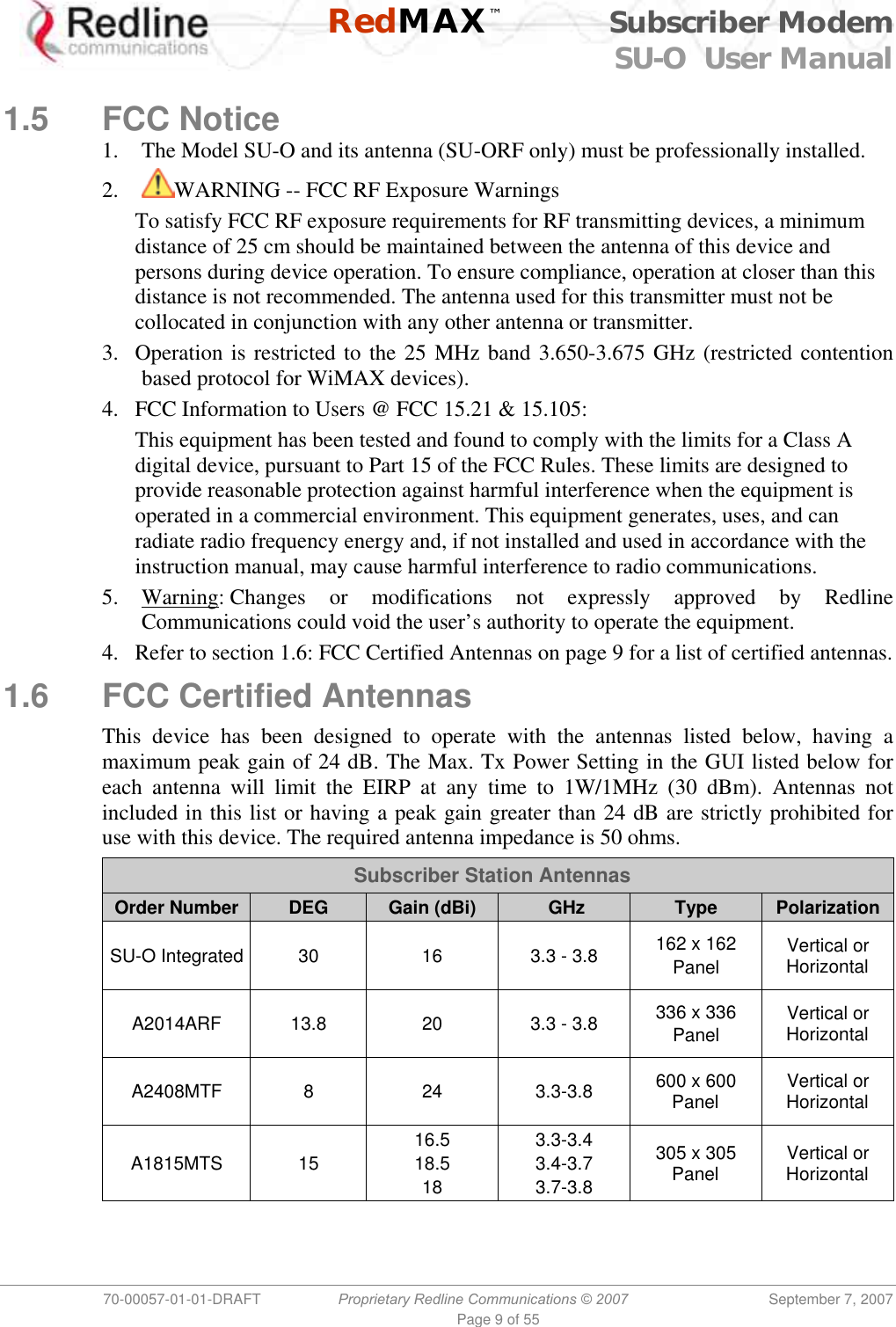
![RedMAX™ Subscriber Modem SU-O User Manual 70-00057-01-01-DRAFT Proprietary Redline Communications © 2007 September 7, 2007 Page 39 of 55 4.3.10 phyConfig - Physical Layer Configuration The phyConfig mode allows you to view and modify the subscriber physical layer (PHY) settings. The following table lists all commands available in this mode. Table 16: CLI - phyConfig - Physical Layer Commands Command Description reset Set all parameters to factory default values. Requires confirmation. set Change physical layer parameter settings. Bandwidth: Channel size (KHz). Selections are: 1750, 3500, or 7000. FftSize: OFDM fft size. Valid settings are: 128, 256, 512, or 1024. PsPerOFDMSymbol: Physical slots per OFDM symbol value in PS. SmplFactorNum: Above the fraction line in the sampling factor (ns). Normally set to 8 nsec. SmplFactorDen: Under the fraction line in the sampling factor (ns). Normally set to 7 nsec. CyclicPrefix: Cyclic prefix (CP). The guard interval is used to factor out multipath effect. Valid settings are: 4, 8, 16, and 32. Default value for subscriber is 16 (1/16). Example: Enter the following command string to set the channel size to 3500 KHz: set Bandwidth 3500 [Enter] show Display the current setting for all parameters. For example: Structure --- <<SS Mmgt PHY Configuration Parameter>> Bandwidth:..........3500 kHz FftSize:............256 PsDuration:.........1000 PsPerOFDMSymbol:....68 SmplFactorNum:......8 SmplFactorDen:......7 nsec CyclicPrefix:.......16 PS](https://usermanual.wiki/Redline-Communications/SUOA/User-Guide-840520-Page-39.png)
![RedMAX™ Subscriber Modem SU-O User Manual 70-00057-01-01-DRAFT Proprietary Redline Communications © 2007 September 7, 2007 Page 42 of 55 4.3.14 set - Set Commands The set mode can be used to directly modify all available subscriber parameters. The parameters listed in this table do not have a separate mode, and can openly be modified by the set command. Enter a new value for one or more fields in mode. set [Enter] Display all fields. Modify selected field(s). set [mode] [field] [value] [value] [field] […] <ENTER> Table 20: CLI - set - Modify Subscriber Parameters Command Description dhcpRelayAgent Use this setting to enable or disable the DHCP relay setting. 0 -- Disable DHCP relay agent. 1 -- Enable DHCP relay agent. This feature must be enabled to use DHCP Option 82. dlLearnFilter Use this setting to enable or disable the DHCP relay setting. 0 -- Disable filter - Do not filter DL packets. 1 -- Enable filter - Only forward DL packets based on learned hosts. ethernet Use this setting to modify the Ethernet port auto negotiation, link speed, and duplex settings. AutoNegEnabled <value> 0 -- Disabled 1 -- Enabled. LinkSpeed <value> 0 -- 10M 1 -- 100M. LinkDuplex <value> 0 -- Half 1 -- Full. managedSS The managedSS command allows you to configure the subscriber for independent operation, or enable management using the RedMAX EMS system. The managedSS parameter is controlled from root mode. The following table lists all commands available for managedSS. 0 - Disable remote management 1 - Enable remote management pppoe Enable/Disable DSL Forum VSA in PPPoE Vendor-Specific Tag (RFC4679). 0 - Disable pppoe 1 - Enable pppoe sysContact Enter device administration contact information (255 chars max.). sysLocation Enter the device location (255 characters max.). sysName Enter the device name (255 characters max.).](https://usermanual.wiki/Redline-Communications/SUOA/User-Guide-840520-Page-42.png)
![RedMAX™ Subscriber Modem SU-O User Manual 70-00057-01-01-DRAFT Proprietary Redline Communications © 2007 September 7, 2007 Page 48 of 55 5.3 Subscriber Log Messages Table 26: Troubleshooting - Event Log Messages Log Message Description Add classifier [CID: XXXX, Idx: nn] A classifier with the following CID has been added. Broadcast Opportunity Corrupted Opportunities have been received for initial ranging, but the opportunity is not appropriate (i.e. too short) for this subscriber. Broadcast Ranging Opportunity Received This message indicates that the base station has provided an opportunity for subscriber registration. Broadcast Ranging Opportunity Timeout This message indicates that the base station has not provided an opportunity for new subscriber registration within the last 10 seconds. Classifier deleted [Idx: nn] The specified classifier has been deleted. Classifiers deleted for SF with CID XXXX All classifiers have been cleared for the specified service flow. DCD Receiving Timeout The subscriber has not received downlink channel descriptors for five consecutive opportunities. The subscriber will now restart the ranging process in an attempt to re-establish wireless synchronization. Deregistration DREG-CMD, action code: nn The subscriber has de-registered. Deregistration DREG-CMD, action code: nn base station has requested that subscriber should deregister. DHCP Error There has been an error in obtaining a DHCP lease Downlink Burst Profile Adjusted [BP: nn] Downlink modulation rate has been adjusted by the base station. Downlink Burst Profile Change Attempt [BP: nn] A request to change the downlink modulation rate has been made based on locally configured CINR thresholds. Downlink Channel Inoperable This message is displayed when the subscriber detects the presence of a base station, but is unable to properly synchronize with it. Downlink SF nn changed Changes have been successfully applied to the specified downlink service flow. Downlink SF nn created [CID: XXXX, No.Cls: nn] A downlink service flow has been successfully created. Downlink SF nn not created (no space) [CID: XXXX] The subscriber cannot create the specified DL service flow, as there is not enough remaining memory. DSA Err - DSA-ACK send retries exhausted [SF Id: XXXX] subscriber has attempted to acknowledge a DSA transaction unsuccessfully more than the maximum number of times. DSA Rejected - Service Flow exists [SF Id: XXXX] The service flow ID assigned base station already exists locally in subscriber](https://usermanual.wiki/Redline-Communications/SUOA/User-Guide-840520-Page-48.png)
![RedMAX™ Subscriber Modem SU-O User Manual 70-00057-01-01-DRAFT Proprietary Redline Communications © 2007 September 7, 2007 Page 49 of 55 Table 26: Troubleshooting - Event Log Messages Log Message Description DSC abort by DSC-ACK [SF Id: XXXX] A DSC transaction has been aborted due to an acknowledgement message not being received by the subscriber. DSC Err - DSC-ACK send retries exhausts [SF Id: XXXX] subscriber has attempted to acknowledge a DSC transaction unsuccessfully more than the maximum number of times. DSC Err - DSC-RSP send retries exhausts [SF Id: XXXX] subscriber has attempted to acknowledge a DSC-RSP transaction message unsuccessfully more than the maximum number of times. DSC Err - SF or CLS rejected [SF Id: XXXX] DSC transaction has been rejected by base station. DSC Success [SF Id: XXXX] DSC transaction has been successful. DSC-DSD Reject - SF ID not found base station has requested the deletion of a SFID which does not exist. DSD Success [SF Id: XXXX] DSD transaction has successfully completed. DSx Action [error] There has been an error in the creation of a service flow. The particular failure is detailed in the message text. DSx Add Reject [reason] This message signifies that the addition of a service flow has been rejected by the subscriber. The reason for the failure is included in the message text. Failed to acquire the time-of-day Communication with a ToD (RFC-868) server has not been successful. The correct time of day has not been acquired. According to standard, the subscriber must now perform a MAC reboot and begin network entry again. Initial Ranging at Maximum Power [Adj.: +nn] subscriber has begun initial ranging with a base station, and has reached its maximum Tx power while attempting to establish communication. Initial Ranging at Minimum Power [Adj.: +nn] subscriber has begun initial ranging with a base station, and has reached its minimum Tx power while attempting to establish communication. Initial Ranging Backoff A contention was encountered with another subscriber while attempting to perform initial ranging. The subscriber will wait and try again after the backoff interval. Initial Ranging Parameters Adjusted [TLV Map: XXXXXXX] This message displays the parameter adjustments as requested by the base station. Initial Ranging Success [TLV Map: XXXXXXX] Initial ranging has been completed successfully. Invalid MAC address This message is displayed when the MAC of the subscriber does not belong the Redline. The system will not function in this state. Large Time Adjustment Received An excessively large timing correction has been sent by the base station. This correction has not been applied, though it has been acknowledged.](https://usermanual.wiki/Redline-Communications/SUOA/User-Guide-840520-Page-49.png)
![RedMAX™ Subscriber Modem SU-O User Manual 70-00057-01-01-DRAFT Proprietary Redline Communications © 2007 September 7, 2007 Page 50 of 55 Table 26: Troubleshooting - Event Log Messages Log Message Description Lost DL-MAP The time since the last valid DL MAP was received by the subscriber has exceeded the timeout. The subscriber will now begin the ranging process in an attempt to re-establish wireless synchronization. Lost UL-MAP The time since the last valid UL MAP was received by the subscriber has exceeded the timeout. The subscriber will now begin the ranging process in an attempt to re-establish wireless synchronization. MAC Initialized The MAC processor has completed initialization. MAC Reset: Configuration Change The MAC has required a reset to apply a configuration change that was made by the user. MAC Reset: SC Request (RES-CMD) The base station has requested that the subscriber reset its MAC. MAC Reset: SC Request (RES-CMD) base station has requested that subscriber should reset its MAC. MAC Started The MAC processor has been started. New Cls for SF with CID XXXX A new classifier has been added to the specified service flow. No Maintenance Data Grant Slot T4 IF subscriber has nothing to send, the base station should grant unsolicited bandwidth. subscriber should respond with padding. This message indicates that the base station has not granted this data for 35 seconds. REG Failure - Retries Exhausted The timer above (T6) has been hit 3 times in a row. The subscriber will now reboot and begin scanning for a base station again. REG Success [TLV Map: XXXXXXXX] The subscriber has successfully registered. REG Wait Timeout T6 [nn retries] The subscriber has not received a response to its registration request within 3 seconds. REG_REQ authentication failure - HMAC [CC: nn] With privacy enabled, authentication failed. REG-REQ not sent - no bw granted The subscriber has not been able to send a registration request message to the base station, since the base station has not granted it bandwidth to do so. It cannot request bandwidth, because it is not yet registered. Reset [reason] The subscriber has reset itself. The reason for the reset is included in the message text. Rf Rx Calibration Error Rx Calibration data located in the subscriber’s EEPROM has failed CRC Rf Tx Calibration Error Tx calibration data located in the subscriber’s EEPROM has failed CRC Rng Maintenance Correction Anomaly [TLV Map: XXXXXXXX] An adjustment requested by the base station has failed. Not a fatal error. Rng Maintenance Correction Success [TLV Map: XXXXXXXX] An adjustment requested by the base station has been successfully applied.](https://usermanual.wiki/Redline-Communications/SUOA/User-Guide-840520-Page-50.png)
![RedMAX™ Subscriber Modem SU-O User Manual 70-00057-01-01-DRAFT Proprietary Redline Communications © 2007 September 7, 2007 Page 51 of 55 Table 26: Troubleshooting - Event Log Messages Log Message Description SBC Failure - Retries Exhausted T18 expired beyond the maximum number of allowed retries. SBC Success [TLV Map: XXXXXXXX] The subscriber has successfully negotiated its basic capabilities with the base station. SBC Wait Timeout T18 [nn retries] A SBC request response is not received within 50ms. SBC-REQ not sent - no BW granted base station has not allocated bandwidth to allow subscriber to do SBC and registration Synchronization Completed The subscriber has completed scanning for a downlink channel, and established synchronization with a base station. It will now begin its initial ranging process. System startup [status] The subscriber has begun the bootup sequence. The startup status will be included in the text of this message. Modes specify a possible reason for reboot. TFTP - no response T26 [nn retries] SMC setup has not completed within the allowed time. TFTP Completed Successfully This message confirms that SMC registration has completed. Communication with DHCP and ToD servers was successful. TFTP Success SMC IP, ToD, have been successfully obtained via DHCP.TFTPC failed send SMC has failed, and the subscriber will reset the MAC and begin registration process again. Time-of-day acquired Communication with a ToD (RFC-868) server has been successful. The correct time of day has been acquired. UCD Receiving Timeout 5 uplink channel descriptors in a row have been expected and not received. The subscriber will now restart the ranging process in an attempt to re-establish wireless synchronization. Unicast Initial Ranging No Response T3 [nn retries] The base station has not responded to an initial ranging request sent by the subscriber within 200 ms. Unicast Initial Ranging Retries Exhausted [nn retries] The subscriber has attempted to perform initial ranging 16 times and has failed each time. Unicast Initial Ranging Start [CID: XXXX] The subscriber has received a unicast ranging opportunity Unicast Ranging Abort Indicates that the base station has sent the subscriber a ranging abort, telling it to halt the ranging process. Uplink Channel Parameters Acquired The subscriber has successfully obtained the uplink channel descriptor Uplink SF nn changed Changes have been successfully applied to the specified uplink service flow. Uplink SF nn created [CID: XXXX, No.Cls: nn] An uplink service flow has been successfully created. Uplink SF nn not created (no space) [CID: XXXX] The subscriber cannot create the specified UL service flow, as there is not enough remaining memory.](https://usermanual.wiki/Redline-Communications/SUOA/User-Guide-840520-Page-51.png)
![RedMAX™ Subscriber Modem SU-O User Manual 70-00057-01-01-DRAFT Proprietary Redline Communications © 2007 September 7, 2007 Page 53 of 55 5.4.4 Update Software Procedure 1. Start a telnet session to the subscriber using the following settings: Login: admin Password: admin 2. Enter the 'loadImage' command. The subscriber will prompt you to enter the following information: Server IP address: [enter address of FTP server] File Name: [enter binary file name- including .bin extension] 3. The subscriber performs FTP server authentication with user name 'target' and password 'secret' (these settings cannot be altered). The image will be uploaded to the subscriber and saved in the non-volatile memory (flash). 4. The subscriber must be rebooted to load the new software. Enter the 'reboot' command to reset the unit. The telnet session will be terminated. Example Download Dialog with Subscriber Login: admin Password: admin, welcome to the SS CLI. (Version 0.3) SUO#> loadImage Server IP Address: [enter ftp server IP address here] File Name: [enter binary file name here] Opening FTP connection.....Done Downloading image ............................................................................................……………… Done Programming update........Done Erasing setup partition. Done. Writing setup partition. Done. Erasing boot block. Done Programming boot block. Done Flash programming complete. SUO#>reboot](https://usermanual.wiki/Redline-Communications/SUOA/User-Guide-840520-Page-53.png)