Redline Communications SUOA RedMAX SU-O User Manual 70 00057 01 01 DRAFT
Redline Communications Inc. RedMAX SU-O 70 00057 01 01 DRAFT
User Manual
70-00057-01-01-DRAFT Proprietary Redline Communications © 2007 September 7, 2007
Page 1 of 55
a m
RedMAXTM
Outdoor Wireless Access
Subscriber Modem
User Manual
RedMAX™ Subscriber Modem
SU-O User Manual
70-00057-01-01-DRAFT Proprietary Redline Communications © 2007 September 7, 2007
Page 2 of 55
Copyright Information
All rights reserved September 7, 2007. The information in this document is proprietary to
Redline Communications Inc. This document may not in whole or in part be copied,
reproduced, or reduced to any medium without prior consent, in writing, from Redline
Communications Incorporated.
Contact Information:
Redline Communications Inc.
302 Town Centre Blvd. Suite 100
Markham, ON
Canada L3R 0E8
Web site: http://www.redlinecommunications.com
Sales Inquiries:
North American nainfo@redlinecommunications.com
Toll-free sales 1-866-633-6669
International intlinfo@redlinecommunications.com
Support: www.redlinecommunications.com/support/support_portal.html
Document Control:
70-00057-01-01-RedMAX_Subscriber_Outdoor_SU-O_UserManual-FCC-
20070907a.doc
Disclaimer
The statements, configurations, technical data, and recommendations in this document
are believed to be accurate and reliable, but are presented without express or implied
warranty. Additionally, Redline makes no representations or warranties, either expressed
or implied, regarding the contents of this product. Redline Communications shall not be
liable for any misuse regarding this product. The information in this document is subject
to change without notice.

RedMAX™ Subscriber Modem
SU-O User Manual
70-00057-01-01-DRAFT Proprietary Redline Communications © 2007 September 7, 2007
Page 3 of 55
TABLE OF CONTENTS
1 Important Safety Notices ........................................................................ 7
1.1 Safety Warnings ........................................................................................ 7
1.2 Important Warning Symbols ...................................................................... 7
1.3 CSA Information ........................................................................................ 8
1.4 Information For Use In Canada ................................................................. 8
1.5 FCC Notice................................................................................................ 9
1.6 FCC Certified Antennas ............................................................................ 9
1.7 Frequency Selection................................................................................ 10
1.7.1 General................................................................................................ 10
1.7.2 R&TTE Directive 1999/5/EC Statements............................................. 10
1.8 WEEE Product Return Process............................................................... 12
1.9 Important Service Information ................................................................. 13
2 Overview ................................................................................................ 14
2.1 Features .................................................................................................. 15
2.1.1 IEEE 802.16 WiMAX Compliance ....................................................... 15
2.1.2 PHY Specification................................................................................ 15
2.1.3 Time Division Duplexing (TDD) ........................................................... 15
2.1.4 Coding Rate......................................................................................... 15
2.1.5 Modulation........................................................................................... 15
2.1.6 Reed Solomon Error Correction .......................................................... 16
2.2 Deployment Models................................................................................. 16
2.2.1 PTP Deployment ................................................................................. 16
2.2.2 PMP Deployment................................................................................. 16
2.2.3 Non Line-of-Sight................................................................................. 16
2.2.4 Channelization..................................................................................... 17
2.3 Service Flows .......................................................................................... 18
2.3.1 Service Flow Classification.................................................................. 18
2.3.2 Dynamic Service Addition.................................................................... 18
2.3.3 Uplink Service Flow Scheduling .......................................................... 18
2.3.4 Downlink Service Flow Scheduling...................................................... 19
3 Outdoor Subscriber Features............................................................... 20
3.1 Integrated Antenna (SU-OIA) .................................................................. 20
3.2 Non Integrated Antenna (SU-ORF) ......................................................... 21
3.3 Subscriber Connections and Controls..................................................... 22
3.3.1 Ethernet Port (and Cable).................................................................... 22
3.3.2 RF Port ................................................................................................ 22
3.3.3 Grounding Connection......................................................................... 22
3.3.4 PoE (Power over Ethernet) Power Adaptor......................................... 23
3.4 Mounting the Outdoor Subscriber ........................................................... 24
3.4.1 Outdoor Subscriber with Integrated Antenna ...................................... 24
3.4.2 Outdoor Subscriber with External Antenna ......................................... 25
3.4.3 Antenna Alignment .............................................................................. 25
4 CLI Commands ...................................................................................... 26

RedMAX™ Subscriber Modem
SU-O User Manual
70-00057-01-01-DRAFT Proprietary Redline Communications © 2007 September 7, 2007
Page 4 of 55
4.1 Introduction.............................................................................................. 26
4.2 CLI Modes ............................................................................................... 26
4.2.1 Telnet Connection ............................................................................... 26
4.2.2 Root Commands.................................................................................. 27
4.3 Mode Commands .................................................................................... 28
4.3.1 boardConfig - Board Setup Commands .............................................. 29
4.3.2 bsIdTable - Base Station ID Table Commands ................................... 30
4.3.3 diagStatistics - Diagnostic Statistics.................................................... 31
4.3.4 ethTag - Ethernet Tagging................................................................... 33
4.3.5 installedVer - Installed Version............................................................ 34
4.3.6 ipAddress - IP Address Commands .................................................... 35
4.3.7 loadImage - Download and Activate Software Image.......................... 36
4.3.8 modThresh - Modulation Threshold..................................................... 37
4.3.9 monitor - Monitor Mode ....................................................................... 38
4.3.10 phyConfig - Physical Layer Configuration ........................................... 39
4.3.11 privacySS - Privacy Commands .......................................................... 40
4.3.12 reset - Reset Command ...................................................................... 40
4.3.13 rfConfig - RF Setup Commands .......................................................... 41
4.3.14 set - Set Commands............................................................................ 42
4.3.15 show - Show Commands..................................................................... 43
4.3.16 softwareUpdate - Software Update Commands.................................. 44
4.3.17 status - Status Information................................................................... 45
5 Appendices............................................................................................ 46
5.1 System Technical Specifications............................................................. 46
5.2 Receive Sensitivity .................................................................................. 47
5.3 Subscriber Log Messages....................................................................... 48
5.4 Upgrade Subscriber ................................................................................ 52
5.4.1 FTP Server .......................................................................................... 52
5.4.2 Upgrade Path ...................................................................................... 52
5.4.3 Connection to Subscriber .................................................................... 52
5.4.4 Update Software Procedure ................................................................ 53

RedMAX™ Subscriber Modem
SU-O User Manual
70-00057-01-01-DRAFT Proprietary Redline Communications © 2007 September 7, 2007
Page 5 of 55
LIST OF FIGURES
Figure 1: Notices - WEEE Logo .......................................................................... 12
Figure 2: Intro - RedMAX Subscriber Outdoor System ....................................... 14
Figure 3: System - PTP Line of Sight Deployment.............................................. 16
Figure 4: System - Fresnel Zone......................................................................... 17
Figure 5: System - Non-Line of Sight Deployment.............................................. 17
Figure 6: SU-OIA System Features .................................................................... 20
Figure 7: SU-ORF System Features ................................................................... 21
Figure 8: Outdoor Ethernet Cable - Cable Connection ....................................... 22
Figure 9: Optional Redline-Supplied PoE (Power-over-Ethernet) Power adaptor23
Figure 10: SU-OIA System Connections Diagram .............................................. 24
Figure 11: SU-ORF System Connections Diagram............................................. 25
Figure 12: Subscriber CLI Interface - Login Dialog............................................. 27

RedMAX™ Subscriber Modem
SU-O User Manual
70-00057-01-01-DRAFT Proprietary Redline Communications © 2007 September 7, 2007
Page 6 of 55
LIST OF TABLES
Table 1: Subscriber Station Antennas................................................................... 8
Table 1: R&TTE - Community Language CE Declarations ................................. 10
Table 2: Notices - R&TTE: Countries of Use (3.4 GHz & 3.6 GHz) .................... 12
Table 3: System - PoE Ports............................................................................... 23
Table 4: System - Ethernet Data Port Link/Act LEDs.......................................... 23
Table 5: CLI - Command Groups ........................................................................ 26
Table 6: CLI - Root Mode Commands ................................................................ 27
Table 7: CLI - Root Mode Commands ................................................................ 28
Table 8: CLI - boardConfig - Board Commands.................................................. 29
Table 9: CLI - bsIdTable - Base Station ID Commands ...................................... 30
Table 10: CLI - diagStatistics - Diagnostic Statistics Commands........................ 31
Table 11: CLI - ethTag - Ethernet Tagging Commands ...................................... 33
Table 12: CLI - installedVer - Installed Version Commands................................ 34
Table 13: CLI - ipAddress - IP Address Commands ........................................... 35
Table 14: CLI - modThresh - Modulation Threshold Commands ........................ 37
Table 15: CLI - monitor - Monitor Mode .............................................................. 38
Table 16: CLI - phyConfig - Physical Layer Commands ..................................... 39
Table 17: CLI - privacySS - Privacy Commands................................................. 40
Table 18: CLI - reset - Reset Commands ........................................................... 40
Table 19: CLI - rfConfig - Radio Frequency Commands..................................... 41
Table 20: CLI - set - Modify Subscriber Parameters ........................................... 42
Table 21: CLI - show - Show Commands ........................................................... 43
Table 22: CLI - softwareUpdate - Software Update Commands......................... 44
Table 23: CLI - status - Status Commands ......................................................... 45
Table 24: Specifications - Outdoor Wireless Subscriber Modem........................ 46
Table 25: Reference - RedMAX Subscriber Receive Sensitivity......................... 47
Table 26: Troubleshooting - Event Log Messages.............................................. 48
RedMAX™ Subscriber Modem
SU-O User Manual
70-00057-01-01-DRAFT Proprietary Redline Communications © 2007 September 7, 2007
Page 7 of 55
Chapter
1
1
1
I
Im
mp
po
or
rt
ta
an
nt
t
S
Sa
af
fe
et
ty
y
N
No
ot
ti
ic
ce
es
s
Models This manual describes features and operation of the outdoor SU-OIA/SU-ORF
(SU-O) wireless subscriber modem.
1.1 Safety Warnings
1. Installation of the system must be contracted to a professional installer.
2. Read this user manual and follow all operating and safety instructions.
3. PoE (Power over Ethernet) power adaptor caution:
PoE Power Adapter Caution
Warning to Service Personnel: 48 VDC
Standard Ethernet equipment may be damaged if connected directly to the 'Data +
Power Output' port of a PoE power adaptor.
4. The power requirements are indicated on the product-marking label. Do not exceed
the described limits.
5. Use only a damp cloth for cleaning. Do not use liquid or aerosol cleaners. Disconnect
the power before cleaning.
6. Disconnect power when unit is stored for long periods.
7. The outdoor unit must not be located near power lines or other electrical power
circuits.
8. The system must be properly grounded to protect against power surges and
accumulated static electricity. It is the user’s responsibility to install this device in
accordance with the local electrical codes: correct installation procedures for
grounding of the outdoor unit, mast, lead-in wire and discharge unit, location of
discharge unit, size of grounding conductors and connection requirements for
grounding electrodes.
9. Keep all product information for future reference.
1.2 Important Warning Symbols
The following symbols may be encountered during installation or troubleshooting. These
warning symbols mean danger. Bodily injury may result if you are not aware of the safety
hazards involved in working with electrical equipment and radio transmitters. Familiarize
yourself with standard safety practices before continuing.
Electro-Magnetic Radiation High Voltage
RedMAX™ Subscriber Modem
SU-O User Manual
70-00057-01-01-DRAFT Proprietary Redline Communications © 2007 September 7, 2007
Page 8 of 55
1.3 CSA Information
1. The equipment must be properly grounded according with NEC, ICEC, CEC, and
others, and other local safety code and building code requirements.
2. To meet the over-voltage safety requirements on the telecommunications cables, a
minimum 26 AWG telecommunication line cord must be used.
Pour être en conformance avec les exigences finies de sûreté de sur-tension sur les
câbles de télécommunications un fil de télécommunication ayant un caliber minimum
de 26 AWG doit être utilisé.
3. Reminder to all the broadband wireless system installers: Attention to Section 820-40
of the NEC which provides guidelines for proper grounding, and in particular,
specifies that the cable ground shall be connected to the grounding system of the
building as close to the point of cable entry as is practical.
1.4 Information For Use In Canada
Operation is subject to the following two conditions:
1. This device may not cause interference and
2. This device must accept any interference, including interference that may cause
undesired operation of the device.
IMPORTANT NOTICE: IC Radiation Exposure Statement
This equipment complies with IC radiation exposure limits set forth for an uncontrolled
environment. End users must follow the specific operating instructions for satisfying RF
exposure compliance. To maintain compliance with IC RF exposure compliance
requirements, please avoid direct contact to the transmitting antenna during transmitting.
This transmitter must not be co-located or operating in conjunction with any other
antenna or transmitter.
SU-OIA (integrated antenna): A separation distance of 20 cm or greater should be
maintained between persons and the antenna of the SU-OIA during device operation.
SU-ORF (external antenna): A separation distance of 50 cm or greater should be
maintained between persons and the antenna of the SU-ORF during device operation.
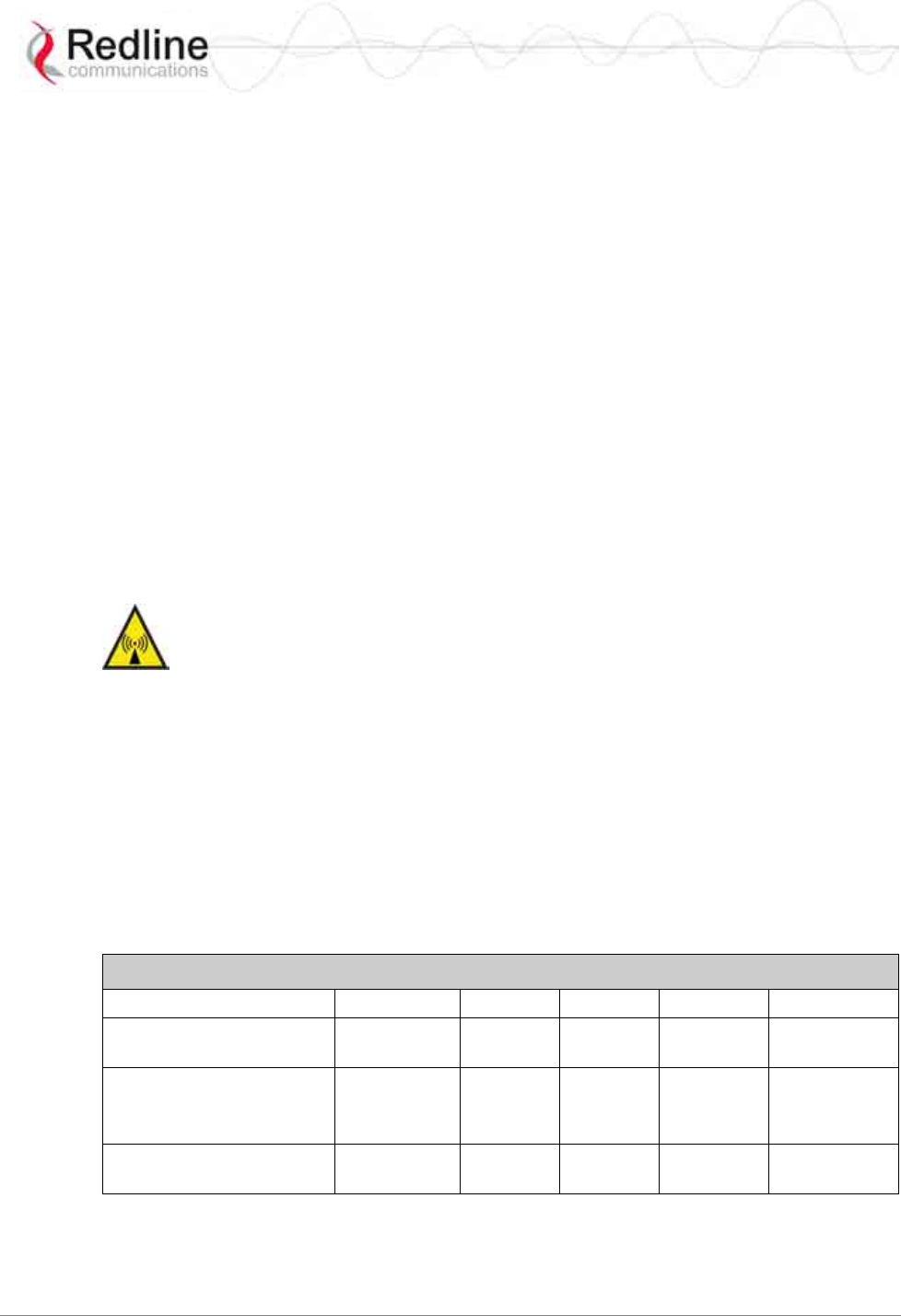
Table 1: Subscriber Station Antennas
Order Number DEG Gain (dBi) GHz Type Polarization
A2014ARF 13.5 20 3.3 - 3.8 Panel Vertical or
Horizontal
A1815MTS 15
16.5
18.5
18
3.3-3.4
3.4-3.7
3.7-3.8
Panel Vertical or
Horizontal
A2408MTF 8 24 3.3-3.8 Panel
Vertical or
Horizontal
RedMAX™ Subscriber Modem
SU-O User Manual
70-00057-01-01-DRAFT Proprietary Redline Communications © 2007 September 7, 2007
Page 9 of 55
1.5 FCC Notice
1. The Model SU-O and its antenna (SU-ORF only) must be professionally installed.
2. WARNING -- FCC RF Exposure Warnings
To satisfy FCC RF exposure requirements for RF transmitting devices, a minimum
distance of 25 cm should be maintained between the antenna of this device and
persons during device operation. To ensure compliance, operation at closer than this
distance is not recommended. The antenna used for this transmitter must not be
collocated in conjunction with any other antenna or transmitter.
3. Operation is restricted to the 25 MHz band 3.650-3.675 GHz (restricted contention
based protocol for WiMAX devices).
4. FCC Information to Users @ FCC 15.21 & 15.105:
This equipment has been tested and found to comply with the limits for a Class A
digital device, pursuant to Part 15 of the FCC Rules. These limits are designed to
provide reasonable protection against harmful interference when the equipment is
operated in a commercial environment. This equipment generates, uses, and can
radiate radio frequency energy and, if not installed and used in accordance with the
instruction manual, may cause harmful interference to radio communications.
5. Warning: Changes or modifications not expressly approved by Redline
Communications could void the user’s authority to operate the equipment.
4. Refer to section 1.6: FCC Certified Antennas on page 9 for a list of certified antennas.
1.6 FCC Certified Antennas
This device has been designed to operate with the antennas listed below, having a
maximum peak gain of 24 dB. The Max. Tx Power Setting in the GUI listed below for
each antenna will limit the EIRP at any time to 1W/1MHz (30 dBm). Antennas not
included in this list or having a peak gain greater than 24 dB are strictly prohibited for
use with this device. The required antenna impedance is 50 ohms.
Subscriber Station Antennas
Order Number DEG Gain (dBi) GHz Type Polarization
SU-O Integrated 30 16 3.3 - 3.8 162 x 162
Panel Vertical or
Horizontal
A2014ARF 13.8 20 3.3 - 3.8 336 x 336
Panel Vertical or
Horizontal
A2408MTF 8 24 3.3-3.8
600 x 600
Panel Vertical or
Horizontal
A1815MTS 15
16.5
18.5
18
3.3-3.4
3.4-3.7
3.7-3.8
305 x 305
Panel Vertical or
Horizontal
RedMAX™ Subscriber Modem
SU-O User Manual
70-00057-01-01-DRAFT Proprietary Redline Communications © 2007 September 7, 2007
Page 10 of 55
1.7 Frequency Selection
1.7.1 General
Operation in the FWA band is subject to license. The radio power and channel frequency
selections must be set correctly before the installed system is allowed to transmit. The
installed system must comply with all governing local, regional, and national regulations.
Contact authorities in the country of installation for complete information regarding the
licensing regime and operating restrictions for that regulatory domain.
1.7.2 R&TTE Directive 1999/5/EC Statements
Installation
The transceiver and antenna equipment must be installed by a qualified professional
installer and must be installed in compliance with regional, national, and local
regulations. It is the responsibility of the system installer and/or system operator to ensure
the installed system does not exceed any operational constraints identified by local
regulations. Refer to the sections in this product User Guide for detailed information about the
correct installation steps to ensure power and frequency settings are set correctly before
connecting the antenna. Operation in the 3.4-3.6 GHz band is subject to license. Authorities
within the country of installation can provide information regarding the licensing regime and
restrictions.
Community Language Declarations
The following table contains community language versions of informal statement in
accordance with Article 6.3 of Directive 1999/5/EC.
Table 1: R&TTE - Community Language CE Declarations
Community language versions of informal statement for inclusion in user
information in accordance with Article 6.3 of Directive 1999/5/EC
Danish Undertegnede Redline Communications erklærer herved, at følgende
udstyr subscriber overholder de væsentlige krav og øvrige relevante
krav i direktiv 1999/5/EF
Hierbij verklaart Redline Communications dat het toestel subscriber in
overeenstemming is met de essentiële eisen en de andere relevante
bepalingen van richtlijn 1999/5/EG
Dutch
Bij deze verklaart Redline Communications dat deze subscriber voldoet
aan de essentiële eisen en aan de overige relevante bepalingen van
Richtlijn 1999/5/EC.
English Hereby, Redline Communications, declares that this subscriber is in
compliance with the essential requirements and other relevant
provisions of Directive 1999/5/EC.
Finnish Redline Communications vakuuttaa täten että subscriber tyyppinen laite
on direktiivin 1999/5/EY oleellisten vaatimusten ja sitä koskevien
direktiivin muiden ehtojen mukainen.
Par la présente Redline Communications déclare que l'appareil
subscriber est conforme aux exigences essentielles et aux autres
dispositions pertinentes de la directive 1999/5/CE
French
Par la présente, Redline Communications déclare que ce subscriber est
conforme aux exigences essentielles et aux autres dispositions de la
directive 1999/5/CE qui lui sont applicables
RedMAX™ Subscriber Modem
SU-O User Manual
70-00057-01-01-DRAFT Proprietary Redline Communications © 2007 September 7, 2007
Page 11 of 55
Table 1: R&TTE - Community Language CE Declarations
Community language versions of informal statement for inclusion in user
information in accordance with Article 6.3 of Directive 1999/5/EC
Hiermit erklärt Redline Communications, dass sich dieser/diese/dieses
subscriber in Übereinstimmung mit den grundlegenden Anforderungen
und den anderen relevanten Vorschriften der Richtlinie 1999/5/EG
befindet". (BMWi)
German
Hiermit erklärt Redline Communications die Übereinstimmung des
Gerätes subscriber mit den grundlegenden Anforderungen und den
anderen relevanten Festlegungen der Richtlinie 1999/5/EG. (Wien)
Greek ΜΕ ΤΗΝ ΠΑΡΟΥΣΑ Redline Communications ∆ΗΛΩΝΕΙ ΟΤΙ subscriber
ΣΥΜΜΟΡΦΩΝΕΤΑΙ ΠΡΟΣ ΤΙΣ ΟΥΣΙΩ∆ΕΙΣ ΑΠΑΙΤΗΣΕΙΣ ΚΑΙ ΤΙΣ
ΛΟΙΠΕΣ ΣΧΕΤΙΚΕΣ ∆ΙΑΤΑΞΕΙΣ ΤΗΣ Ο∆ΗΓΙΑΣ 1999/5/ΕΚ
Italian Con la presente Redline Communications dichiara che questo
subscriber è conforme ai requisiti essenziali ed alle altre disposizioni
pertinenti stabilite dalla direttiva 1999/5/CE.
Portuguese Redline Communications declara que este subscriber está conforme
com os requisitos essenciais e outras provisões da Directiva 1999/5/CE.
Spanish Por medio de la presente Redline Communications declara que el
subscriber cumple con los requisitos esenciales y cualesquiera otras
disposiciones aplicables o exigibles de la Directiva 1999/5/CE
Swedish Härmed intygar Redline Communications att denna subscriber står I
överensstämmelse med de väsentliga egenskapskrav och övriga
relevanta bestämmelser som framgår av direktiv 1999/5/EG.
RedMAX™ Subscriber Modem
SU-O User Manual
70-00057-01-01-DRAFT Proprietary Redline Communications © 2007 September 7, 2007
Page 12 of 55
Table 2: Notices - R&TTE: Countries of Use (3.4 GHz & 3.6 GHz)
Country 3400-3600
MHz Country 3400-3600
MHz Country 3400-3600
MHz
Austria 9 Hungary 9 Poland 9
Belgium 9 Iceland 9 Portugal 9
Bulgaria 9 Ireland 9 Romania 9
Cyprus Italy Slovakia
9
Czech
Republic
9 Latvia 9 Slovenia 9
Denmark 9 Liechtenstein 9 Spain 9
Estonia 9 Lithuania 9 Sweden 9
Finland 9 Luxembourg 9 Switzerland 9
France 9 Malta 9 United
Kingdom
9
Germany 9 Netherlands 9
Greece 9 Norway 9
R&TTE Directive 1999/5/EC - Declarations of conformity are available at the following
web site address:
http://www.redlinecommunications.com/conformance/
1.8 WEEE Product Return Process
Figure 1: Notices - WEEE Logo
In accordance with the WEEE (Waste from Electrical and Electronic Equipment)
directive, 2002/96/EC, Redline Communications equipment is marked with the logo
shown above. The WEEE directive seeks to increase recycling and re-use of electrical
and electronic equipment. This symbol indicates that this product should not be disposed
of as part of the local municipal waste program. Contact your local sales representative
for additional information.

RedMAX™ Subscriber Modem
SU-O User Manual
70-00057-01-01-DRAFT Proprietary Redline Communications © 2007 September 7, 2007
Page 13 of 55
1.9 Important Service Information
1. Refer all repairs to qualified service personnel. Do not remove the covers or modify
any part of this device, as this voids the warranty.
2. Disconnect the power to this product and return it for service if the following
conditions apply:
a) The unit does not function after following the operating instructions
outlined in this manual.
b) Liquid has been spilled or a foreign object is inside.
c) The product has been dropped or the housing is damaged.
3. Record the serial number on your registration card for future reference.
4. Redline does not endorse or support the use of outdoor cable assemblies: i) not
supplied by Redline, ii) third-party products that do not meet Redline's cable and
connector assembly specifications, or iii) cables not installed and weatherproofed as
specified in the Installation Guidelines manual (70-00068-01-XX). Refer to the
Redline Limited Standard Warranty and RedCare service agreements.
RedMAX™ Subscriber Modem
SU-O User Manual
70-00057-01-01-DRAFT Proprietary Redline Communications © 2007 September 7, 2007
Page 14 of 55
Chapter
2
2
2
O
Ov
ve
er
rv
vi
ie
ew
w
Congratulations on your purchase of the Redline WiMAX Forum Certified™ subscriber
wireless broadband product. Redline Communications is a world leader in design and
production of WiMAX and proprietary Broadband Fixed Wireless (BFW) systems.
The outdoor subscriber is carrier class high-speed IEEE 802.16-2004 WiMAX compliant
for point-to-point (PTP) and point-to-multipoint (PMP) deployment.
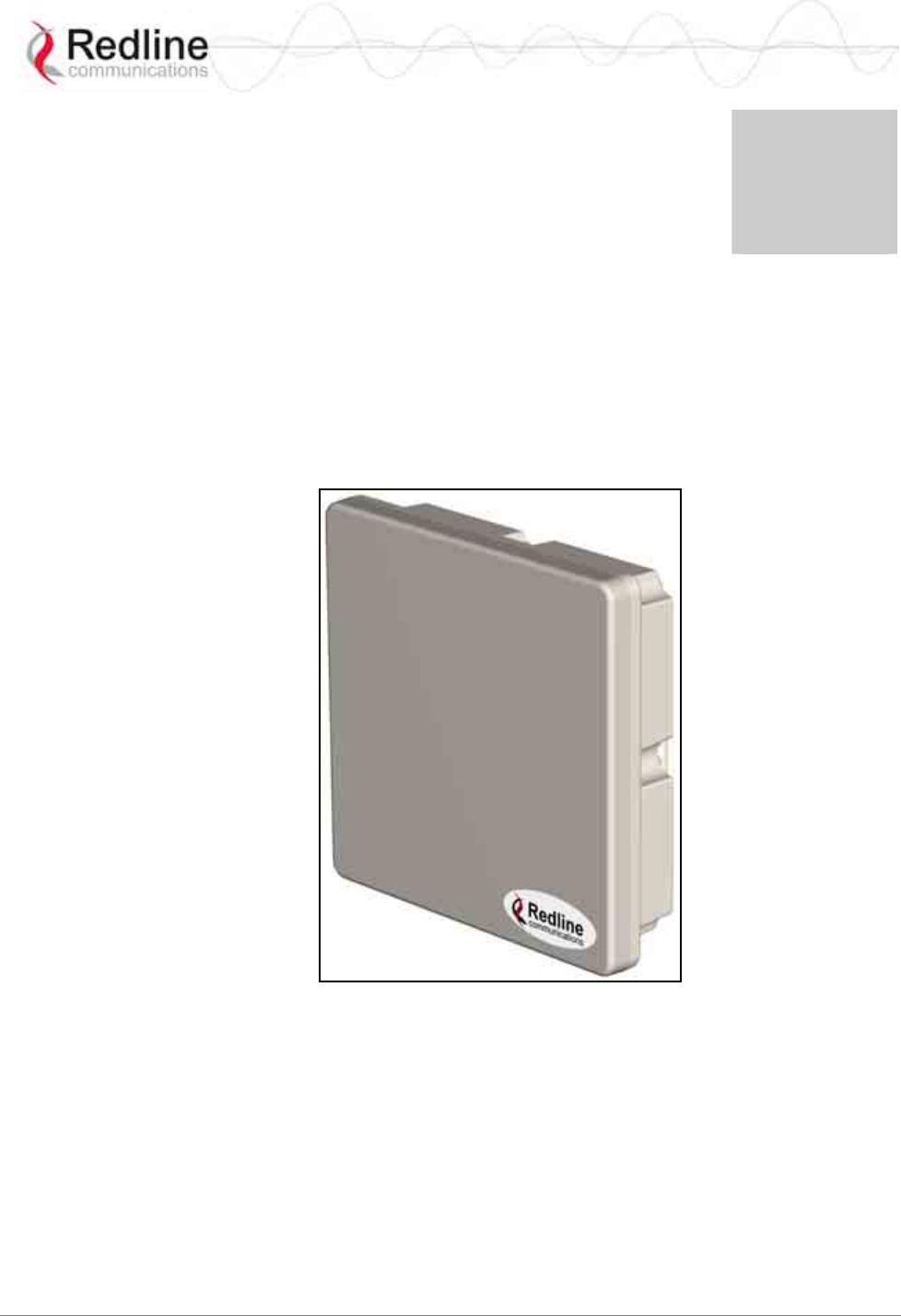
Figure 2: Intro - RedMAX Subscriber Outdoor System

RedMAX™ Subscriber Modem
SU-O User Manual
70-00057-01-01-DRAFT Proprietary Redline Communications © 2007 September 7, 2007
Page 15 of 55
2.1 Features
2.1.1 IEEE 802.16 WiMAX Compliance
The IEEE 802.16-2004 specifications describe a PMP broadband wireless access
standard for systems operating in the frequency range of 2-11 GHz, and 10-66 GHz. This
standard includes descriptions for both the Media Access Control (MAC) and the
physical (PHY) layers. Note that the 802.16-2004 standards are subject to amendment,
and the subscriber product design compliance applies to a specific revision of the
standard. The RedMAX product does not support mesh communication, but does support
subscriber-to-subscriber communication using TLS.
Redline is an active member of the WiMAX Forum™ and is participating in
interoperability testing in the WiMAX Forum. Redline is also an active member of the
IEEE 802.16-2004 standards committee and has been instrumental in creating the original
802.16-2004 standards, and is active in recommending, writing and following-up work on
new amendments to the 802.16-2004 specifications.
2.1.2 PHY Specification
The subscriber system is designed for 2-11 GHz operation based on the WirelessMAN-
OFDM PHY definition in the IEEE 802.16-2004 specifications. The subscriber uses
Orthogonal Frequency Division Multiplexing (OFDM). OFDM is a multi-carrier
transmission technique where the data stream is split and transmitted (at a reduced rate)
in parallel streams on separate sub-carriers. OFDM uses the Fast Fourier Transform
(FFT) algorithm to implement modulation and demodulation functions. Using adequate
channel coding and bit-interleaving, OFDM performs very well in severe multipath
environments, mitigates frequency-selective fading, and provides high spectral
efficiency.
2.1.3 Time Division Duplexing (TDD)
The subscriber system uses time division duplexing (TDD) to transmit and receive on the
same RF channel. The subscriber can also transmit and receive using separate RF
channels, referred to as half-duplex FDD (HD-FDD). These are both non-contention
based methods for providing an efficient and predictable two-way PTP or PMP cell
deployment. All uplink and downlink transmission scheduling is managed by the
WiMAX base station. The base station sends data traffic to subscribers, polls for grant
requests, and sends grant acknowledgements based on the total of all traffic to all
subscribers.
2.1.4 Coding Rate
Each burst of data transmitted over the air is padded with redundant information to make
it resistant to errors introduced during transmission. The coding rate is the ratio of user
data to the total data transmitted including the redundant error correction data. The
subscriber supports coding rates of 1/2, 2/3, and 3/4.
2.1.5 Modulation
The modulation technique specifies how the data is coded within the OFDM carriers. The
subscriber supports BPSK, QPSK, 16 QAM, and 64 QAM modulation.
RedMAX™ Subscriber Modem
SU-O User Manual
70-00057-01-01-DRAFT Proprietary Redline Communications © 2007 September 7, 2007
Page 16 of 55
2.1.6 Reed Solomon Error Correction
Outer Reed-Solomon and inward Convolution Coding (RS-CC) error correction is
enabled for all traffic rates, with the exception of BPSK 1/2 where only inward
Convolution Coding is used. These low-level processes can correct bursts of errors in
received messages and reduce the number of retransmissions.
2.2 Deployment Models
The subscriber supports point to point (PTP) and point to multipoint (PMP) deployment
scenarios.
2.2.1 PTP Deployment
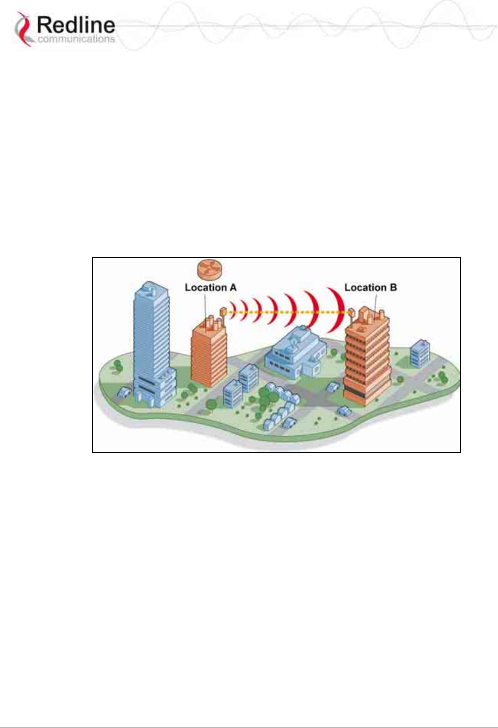
When deployed in a PTP configuration the base station establishes a dedicated bi-
directional link to a single subscriber. The PTP deployments typically use a directional
narrow beam antenna for both ends of the link.
Figure 3: System - PTP Line of Sight Deployment
2.2.2 PMP Deployment
When deployed in a PMP configuration the base station establishes bi-directional links to
more than one subscriber. The PMP deployments typically use a wide beam (sector)
antenna at the base station and a narrow beam antenna at the subscriber. Service flows are
used to police service level agreements for each subscriber.
2.2.3 Non Line-of-Sight
The subscriber system supports line-of-sight (LOS), optical line-of-sight (OLOS), and
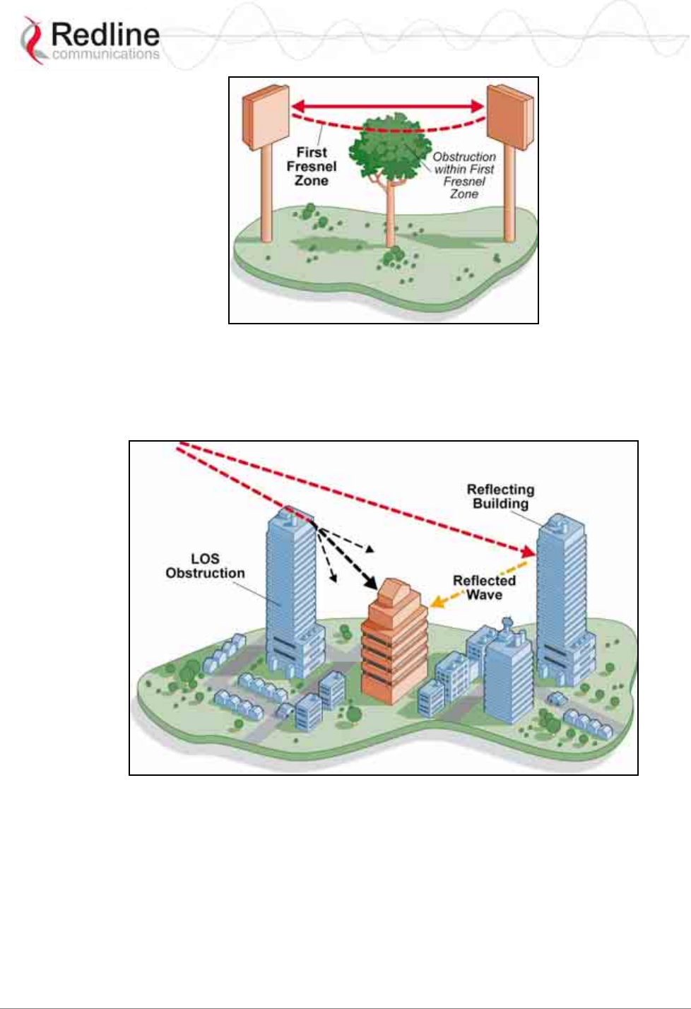
non line-of-sight (NLOS) operation. A clear LOS link has no obstacles within 60% of the
first Fresnel zone of the direct path. An OLOS link has obstructions within 60% of the
first Fresnel zone, but a visible path exists from the base station to the subscriber.
RedMAX™ Subscriber Modem
SU-O User Manual
70-00057-01-01-DRAFT Proprietary Redline Communications © 2007 September 7, 2007
Page 17 of 55
Figure 4: System - Fresnel Zone
A wireless link is considered non LOS if natural or man-made structures block the visible
path between the base station and subscriber. In this case, a wireless link can be
established only if a reflective path can be established between the base station and
subscriber.
Figure 5: System - Non-Line of Sight Deployment
2.2.4 Channelization
The subscriber is a frequency-specific system, with the frequency band defined by the
internal transceiver unit. The use of the operating band must be in accordance with
European Conference of Postal and Telecommunications Administrations (CEPT)
Recommendation 14-03.
The subscriber divides the available frequency band into channels. Allocation of channels
during deployment is dependent on spectrum availability in the licensed FWA band
(3400-3600 MHz) and local licensing requirements and conditions. Channel selection

RedMAX™ Subscriber Modem
SU-O User Manual
70-00057-01-01-DRAFT Proprietary Redline Communications © 2007 September 7, 2007
Page 18 of 55
allows planners to obtain the maximum geographic coverage, while avoiding frequency
contention in adjacent sectors.
2.3 Service Flows
Service flows are a key feature of the 802.16 standard. A Service Flow represents a
unidirectional data flow having separate QoS settings for uplink and downlink. Service
flows provide the ability to set up multiple connections to each subscriber in a sector.
Separate service flows can be established for uplink and downlink traffic, where each
service flow is assigned a unique service level category and separate QoS settings. This
feature allows segregation of high-speed/high-priority traffic from less time-critical
flows.
2.3.1 Service Flow Classification
Data packets are forwarded by the subscriber based on classification rules. Classification
rules require examining each packet for pattern matches such as destination address,
source address, or VLAN tag. All classification is defined at the base station and the
classification parameters are downloaded to the subscriber.
RedMAX supports service flows with different classification types including: 802.3
Ethernet, 802.1Q VLAN, IPV4, IPV4 Over 802.3 and IPV4 Over 802.1Q -- with options
to classify based on Source and Dest of MAC and IP addresses, VLAN tag and Vlan
priority, Src and Dst port number, TOS Value and Ethernet protocol type.
2.3.2 Dynamic Service Addition
Service flows are defined and stored in the base station. For each service flow to be
established, the base station sends a setup message to the subscriber specifying the
required set of QoS parameters. The subscriber responds to each request by accepting or
rejecting the setup message.
A service flow may be pre-provisioned or can be dynamically created and deleted
without service outage. This is useful for supporting multiple subscribers in a single
sector. New subscribers can be added and existing subscribers can be removed or have
service levels modified.
Setup messages are sent by the base station following any subscriber power-cycle, loss
and recovery of the wireless link to a subscriber, or any service flow add/delete operation
at the base station.
2.3.3 Uplink Service Flow Scheduling
The base station enforces QoS settings for each service flow by controlling all uplink and
downlink traffic scheduling. This provides non-contention based traffic model with
predictable transmission characteristics. By analyzing the aggregate requests of all
subscribers, the base station ensures that uplink and downlink traffic conforms with the
current service level agreements (SLAs). Centralized scheduling increases traffic
predictability, eliminates contention, and provides maximum opportunity for reducing
overhead.

RedMAX™ Subscriber Modem
SU-O User Manual
70-00057-01-01-DRAFT Proprietary Redline Communications © 2007 September 7, 2007
Page 19 of 55
Real-Time Polling Service (rt-PS)
The base station schedules a continuous regular series of transmit opportunities for the
subscriber to send variable size data packets. The grant size is based on the current data
transfer requirement. Typical applications include streaming MPEG video or VOIP with
silence suppression. This is efficient for applications that have a real-time component and
continuously changing bandwidth requirements.
Non-Real-Time Polling Service (nrt-PS)
The base station schedules regular transmit opportunities for the subscriber to send
variable size data packets. Typical applications may include high bandwidth FTP. The
polling period may typically be one second or less, even during periods of network
congestion.
Best Effort (BE)
The base station schedules transmit opportunities for the subscriber to send traffic based
on unused bandwidth after all higher level traffic scheduling requirements are serviced.
Typical applications may include Internet access and email. Best effort service flows can
be assigned a priority of 0 to 7.
Unsolicited Grant Service (UGS)
The base station schedules a continuous series of transmit opportunities for the subscriber
to send fixed size data packets. This schedule supports real-time applications including
VoIP or TDM transport. The UGS pre-scheduled grants guarantee reserved bandwidth
and reduce latency introduced by repetitive grant requests. The service flow will not
transmit packets larger than nominal grant interval.
2.3.4 Downlink Service Flow Scheduling
The base station schedules downlink traffic on active service flows based on the
minimum reserved data rate (CIR), traffic priority, and maximum latency.
RedMAX™ Subscriber Modem
SU-O User Manual
70-00057-01-01-DRAFT Proprietary Redline Communications © 2007 September 7, 2007
Page 20 of 55
Chapter
3
3
3
O
Ou
ut
td
do
oo
or
r
S
Su
ub
bs
sc
cr
ri
ib
be
er
r
F
Fe
ea
at
tu
ur
re
es
s
The RedMAX subscriber can be deployed with an integrated antenna or an external
antenna.
3.1 Integrated Antenna (SU-OIA)
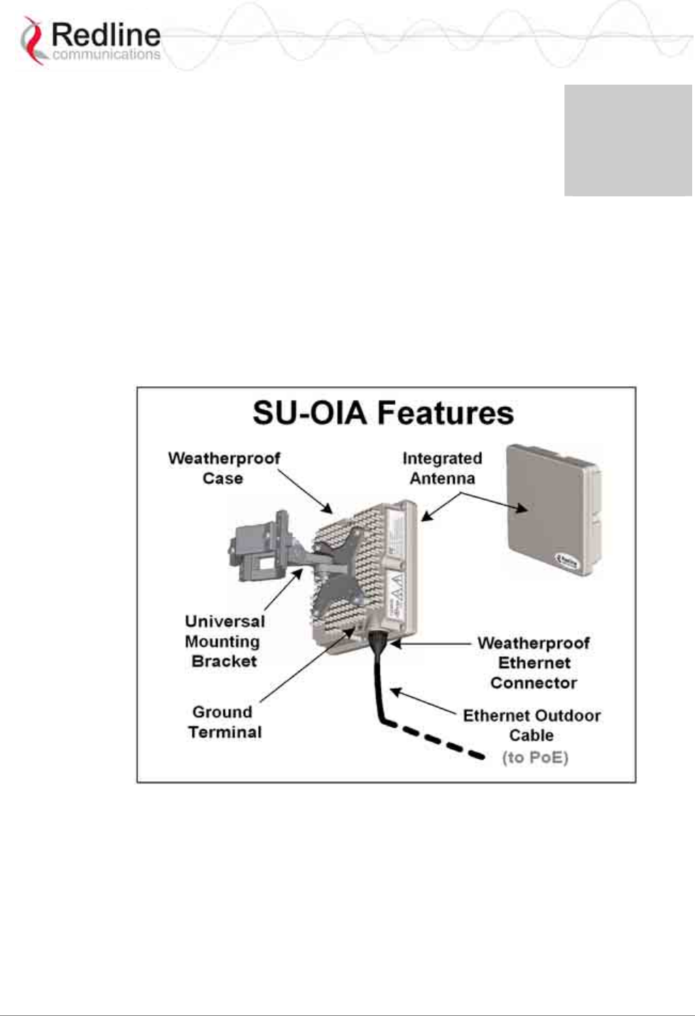
This subscriber with integrated antenna consists of an outdoor radio (transceiver and
antenna) and an indoor power-block with network connections. The subscriber
electronics are housed in a weatherproof aluminum alloy case.
Figure 6: SU-OIA System Features
The SU-OIA system includes:
- Outdoor subscriber with integrated antenna
- Universal mounting bracket
Optional SU-OIA equipment includes:
- Outdoor Ethernet cable with weatherproof connector
- Indoor Power over Ethernet (PoE) power adaptor with AC power cord (NA/UK/EU)
- Lightning/surge protection
RedMAX™ Subscriber Modem
SU-O User Manual
70-00057-01-01-DRAFT Proprietary Redline Communications © 2007 September 7, 2007
Page 21 of 55
3.2 Non Integrated Antenna (SU-ORF)
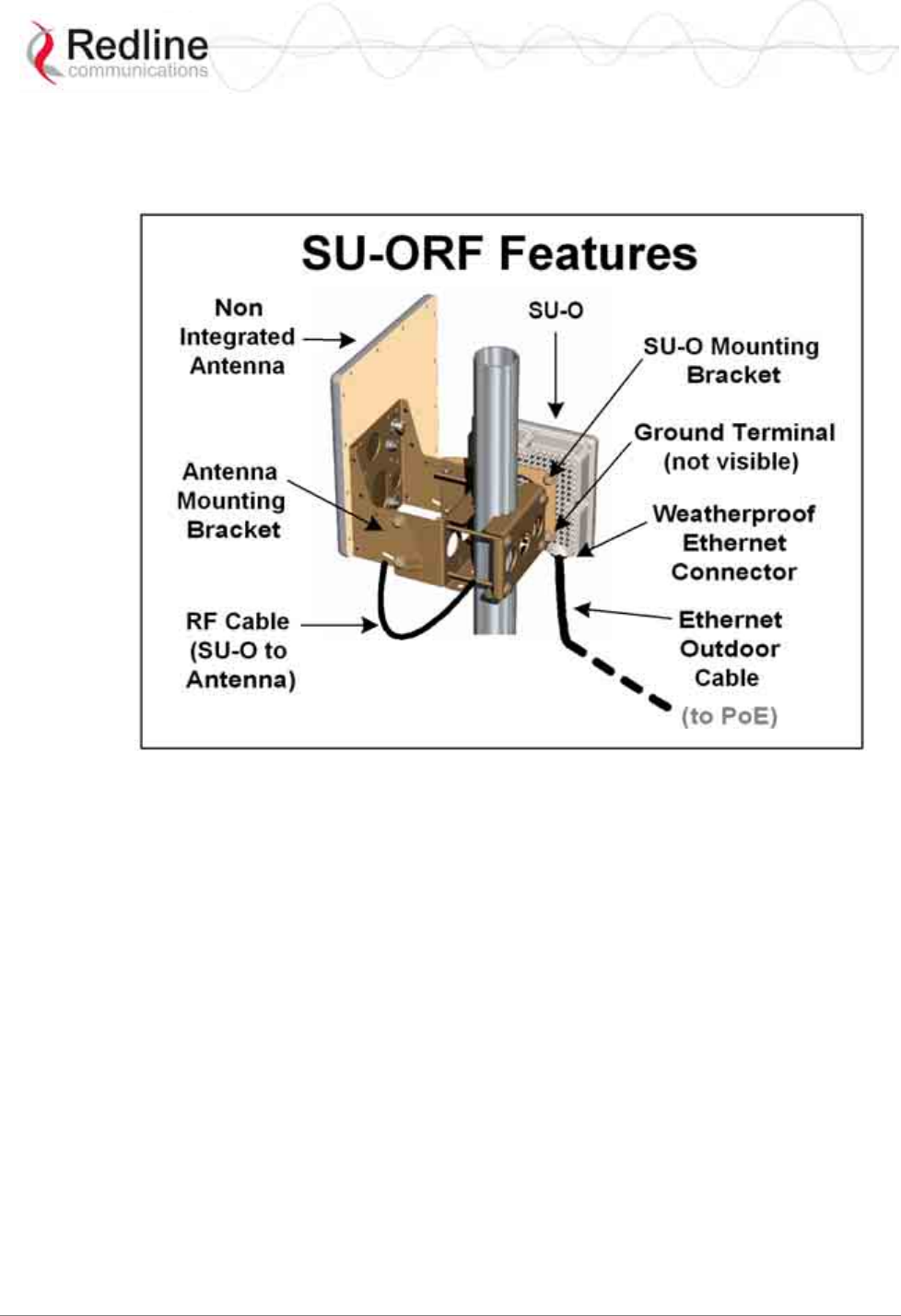
This outdoor subscriber is housed in a weatherproof aluminum alloy case and features an
RF connector for connection to an external antenna.
Figure 7: SU-ORF System Features
The SU-ORF system includes:
- Outdoor subscriber with N-type RF output
- Flat-plate mounting adapter
- Antenna
- Heavy duty mounting bracket
- 40 cm (16") RF cable (N-type connector, 50 Ohm)
Optional SU-OIA equipment includes:
- Outdoor Ethernet cable with weatherproof connector
- Indoor Power over Ethernet (PoE) power adaptor with AC power cord (NA/UK/EU)
- Lightning/surge protection
RedMAX™ Subscriber Modem
SU-O User Manual
70-00057-01-01-DRAFT Proprietary Redline Communications © 2007 September 7, 2007
Page 22 of 55
3.3 Subscriber Connections and Controls
3.3.1 Ethernet Port (and Cable)
The auto-sensing 10/100Base-T Ethernet port connects through the outdoor Ethernet
cable to a PoE power adaptor/CO switch. The SU-O receives DC power and exchanges
data with the network through this port (straight-through connection).
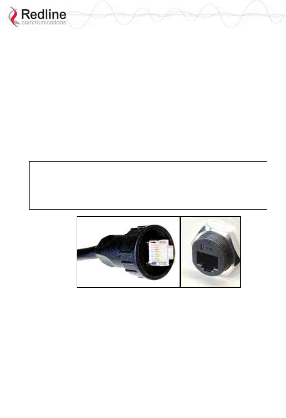
The SU-O cable access entrance is equipped with a weatherproof seal. The outdoor end
of the Redline supplied outdoor (hardened) CAT-5 Ethernet cable is terminated with an
environmentally sealed RJ-45 connector for connection to the subscriber. The minimum
diameter to pass this connector through a conduit or hole is 26 mm (1 in).
The indoor end of the Redline supplied outdoor (hardened) CAT-5 Ethernet cable is
terminated with a standard indoor RJ-45 connector for connection to a PoE power
adaptor/CO switch. The minimum diameter to pass this connector through a conduit or
hole is 18 mm (11/16 in).
Important -- Warranty Information -- Ethernet Cable
Redline does not endorse or support the use of outdoor cable assemblies: i) not supplied
by Redline, ii) third-party products that do not meet Redline's cable and connector
assembly specifications, or iii) cables not installed and weatherproofed as specified in the
Installation Guidelines manual (70-00068-01-XX). Refer to the Redline Limited Standard
Warranty and RedCare service agreements.
Figure 8: Outdoor Ethernet Cable - Cable Connection
3.3.2 RF Port
An external RF connector is provided only on the outdoor subscriber with external
antenna (SU-ORF) model. The transceiver RF port (female N-type connector) is used for
sending/receiving the RF signal to/from the antenna. A short coaxial cable is provided to
connect the transceiver to the antenna.
3.3.3 Grounding Connection
A ground terminal is located on the rear of the subscriber. Use this screw to terminate the
ground wires. Correct grounding is very important for safe operation of wireless
equipment. Ensure that all grounding connections are in accordance with local and
national standards.
RedMAX™ Subscriber Modem
SU-O User Manual
70-00057-01-01-DRAFT Proprietary Redline Communications © 2007 September 7, 2007
Page 23 of 55
3.3.4 PoE (Power over Ethernet) Power Adaptor
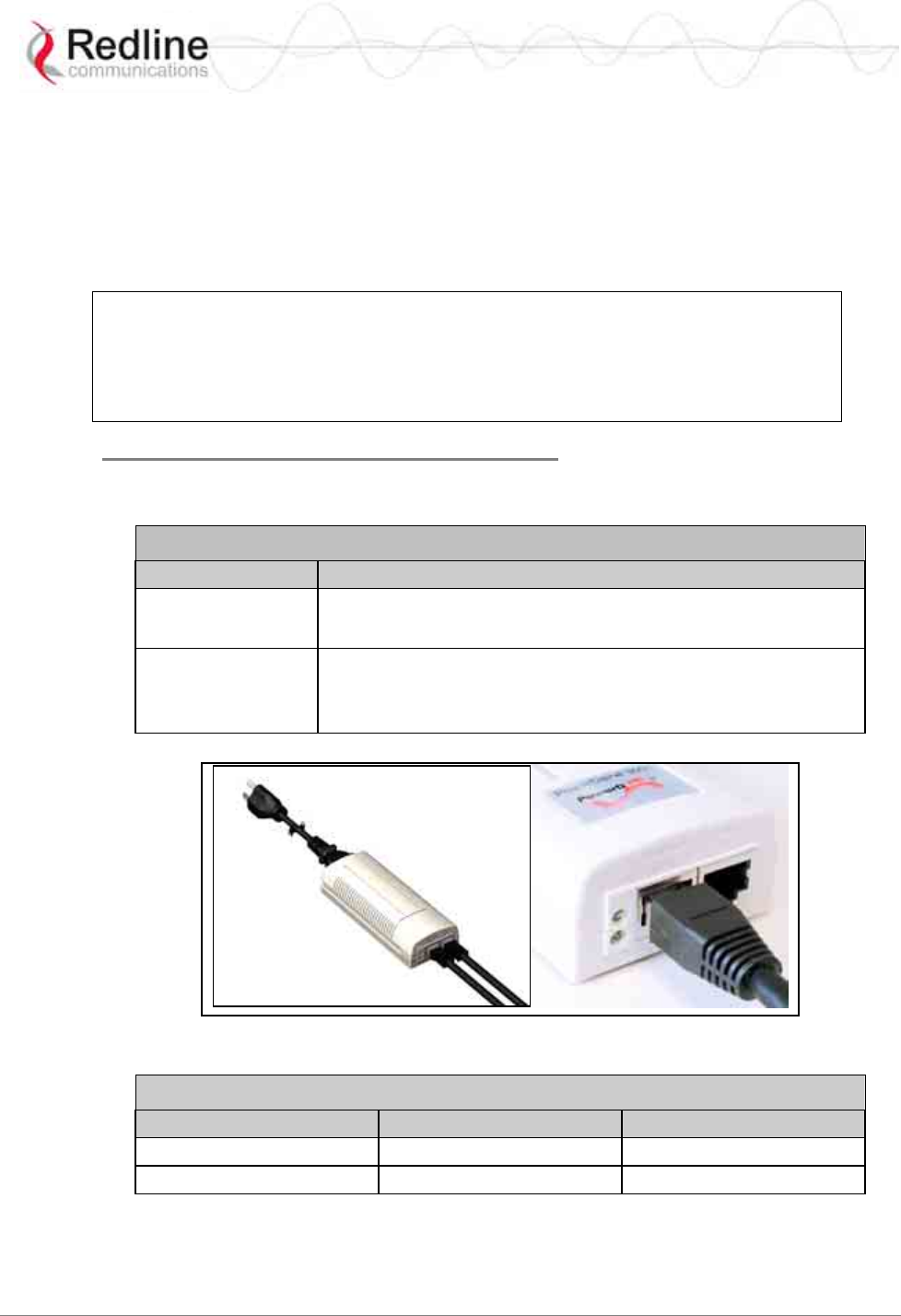
The SU-O may be powered using a stand-alone PoE power adaptor, or by a central office
switch equipped with RJ-45 sockets that provide PoE power and data to the SU-O device.
All PoE devices must have metal-lined RJ-45 sockets that provide a protective ground
connection to the Ethernet cable shield. The PoE power adaptor may be supplied by
Redline as a stand-alone AC powered device.
<
Important -- PoE Equipment
The Ethernet outdoor cable is supplying a protective ground connection for the
Ethernet cable. Customer supplied PoE devices (e.g., central office switches
equipped with RJ-45 sockets that provide PoE power and data) must have metal-
lined RJ-45 sockets providing a protective ground connection to the cable shield.
Redline Supplied PoE Power Adapter
The Redline supplied PoE power adaptor source is auto-sensing 110-240 (nominal) VAC.
The PoE power adaptor provides two Ethernet interfaces:
Table 3: System - PoE Ports
Port Description
DATA IN The auto-sensing 10/100Base-T Ethernet port (RJ-45
socket) for connection to the network equipment.
DATA &
POWER OUT The auto-sensing 10/100Base-T Ethernet port (RJ-45
socket) port is used to carry signals and source power to
the outdoor subscriber outdoor unit.
Figure 9: Optional Redline-Supplied PoE (Power-over-Ethernet) Power adaptor
Table 4: System - Ethernet Data Port Link/Act LEDs
LED Port Power Output
Solid Connected Power is active
Blink Not connected Out of range
RedMAX™ Subscriber Modem
SU-O User Manual
70-00057-01-01-DRAFT Proprietary Redline Communications © 2007 September 7, 2007
Page 24 of 55
3.4 Mounting the Outdoor Subscriber
Refer to the RedMAX Installation Guide (P/N: 70-00059) for detailed instructions.
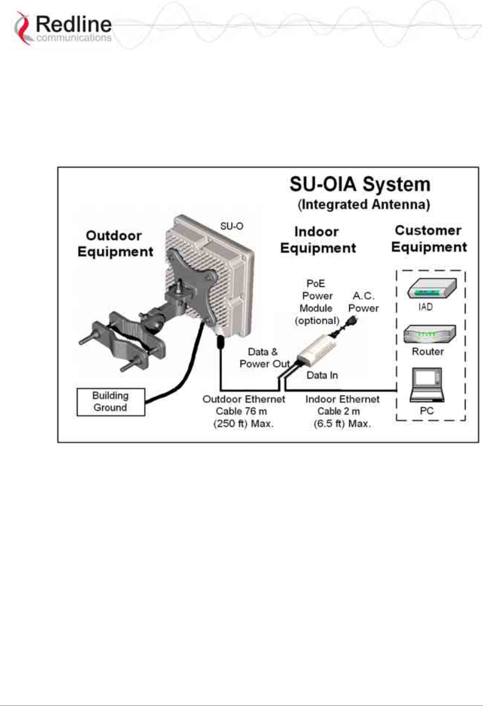
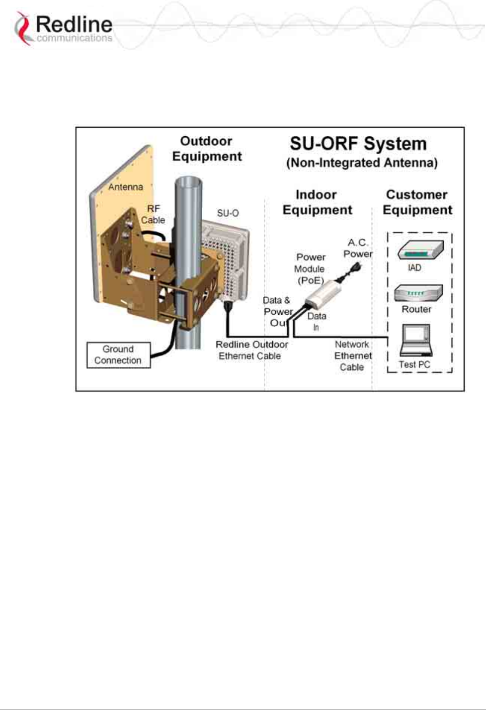
3.4.1 Outdoor Subscriber with Integrated Antenna
The SU-OIA has an integrated flat panel antenna. The vertical mount bracket can
accommodate a flat vertical surface or 2.45 - 11.45 cm (1 - 4 ½ in) OD masts found on
many commercial tower installations.
Figure 10: SU-OIA System Connections Diagram
RedMAX™ Subscriber Modem
SU-O User Manual
70-00057-01-01-DRAFT Proprietary Redline Communications © 2007 September 7, 2007
Page 25 of 55
3.4.2 Outdoor Subscriber with External Antenna
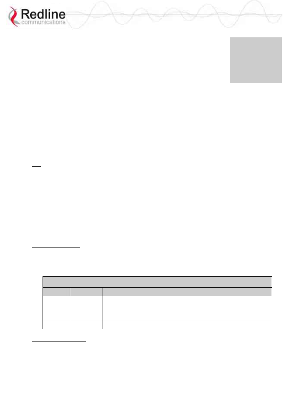
The SU-ORF system is supplied with an N-type RF connector for connection to an
external high gain antenna. The vertical mount bracket can accommodate most 4.45 cm
to 11.45 cm (1 ¾' - 4 ½ in) OD masts found on many commercial tower installations.
Figure 11: SU-ORF System Connections Diagram
3.4.3 Antenna Alignment
The outdoor subscriber includes an audible antenna alignment tool to assist in pointing
the antenna for maximum signal strength. The signal will sound infrequently when a low
signal is detected, and more often as the signal strength increases. Refer to the outdoor
subscriber Installation Guidelines for detailed information.
RedMAX™ Subscriber Modem
SU-O User Manual
70-00057-01-01-DRAFT Proprietary Redline Communications © 2007 September 7, 2007
Page 26 of 55
Chapter
4
4
4
C
CL
LI
I
C
Co
om
mm
ma
an
nd
ds
s
This section describes the subscriber CLI commands.
Important: Access to these commands is password protected. Only authorized
professional installation and service personnel are allowed access to these controls.
4.1 Introduction
The subscriber can be configured using a Telnet connection established through the
subscriber Ethernet port or over the wireless interface from the base station. The CLI can
not be used to setup service flows. All service flows will be setup by the base station.
4.2 CLI Modes
The subscriber CLI interface supports several modes of operation. From root mode you
can display a list of all user modes, reboot the subscriber system, and logout from the
Telnet session. Monitor mode provides a dynamic display of the current system statistics,
updated each few seconds. Configuration modes allow you to view and adjust the
subscriber network and wireless settings.
4.2.1 Telnet Connection
Telnet Login
Type 'telnet' followed by the IP address of the subscriber system, depress ENTER, and
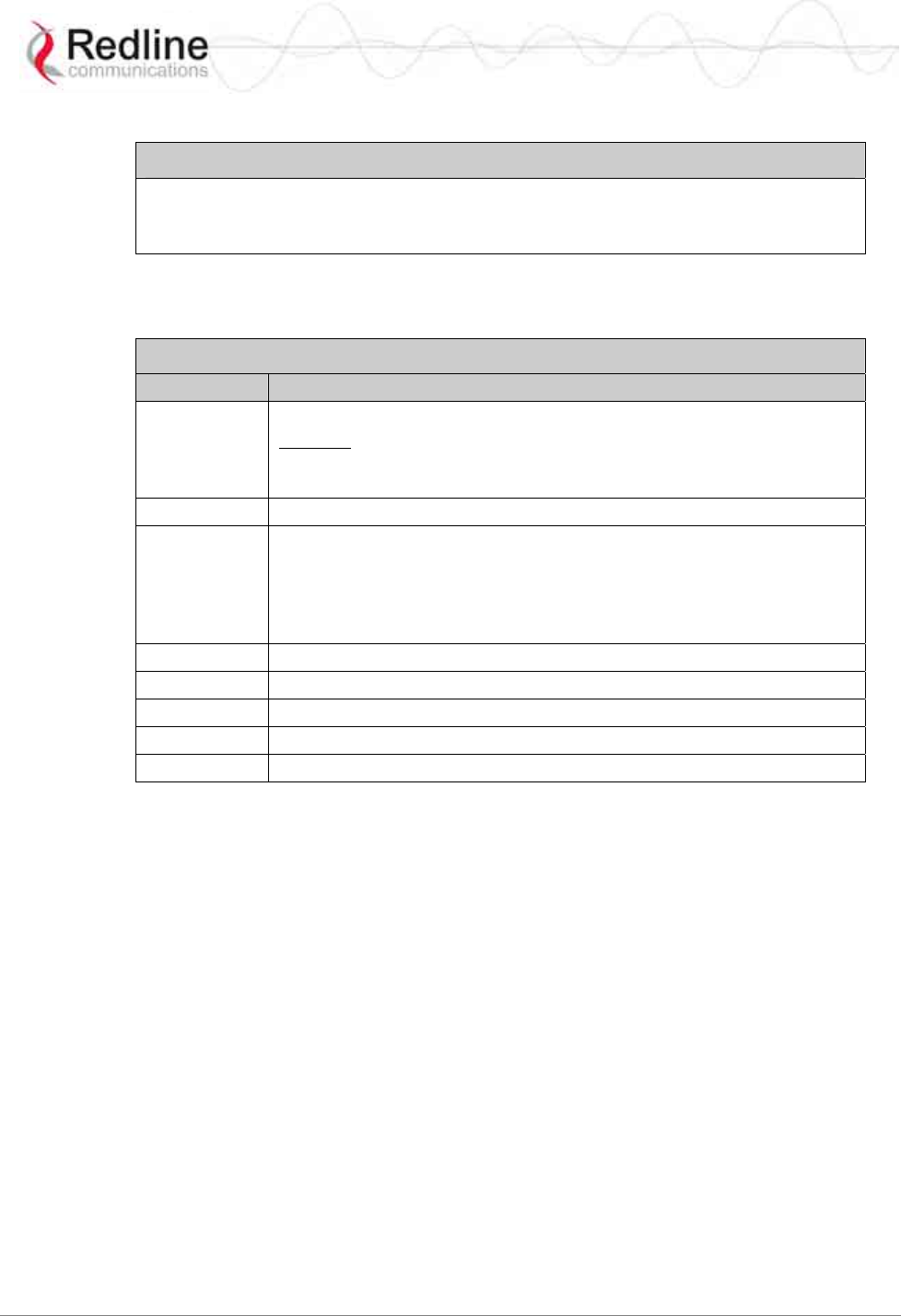
enter the account and password when prompted. The subscriber supports two separate
user accounts:
Table 5: CLI - Command Groups
Account Password Description
admin admin Full system control
user2 user2 Read-only with some functional restrictions (not allowed to use
the 'set' command).
guest guest Same as user2.
Telnet Logout
To exit from the Telnet session, you must be in the root directory. Go to the root
directory by typing:
Exit [ENTER] or CTRL-Z (hold down the CTRL key and depress Z)
Exit from a CLI session by typing:
logout [ENTER]
The system prompts for logout confirmation. Depress 'Y' to complete the logout process.
RedMAX™ Subscriber Modem
SU-O User Manual
70-00057-01-01-DRAFT Proprietary Redline Communications © 2007 September 7, 2007
Page 27 of 55
The system displays a welcome message when successfully logged in.
Figure 12: Subscriber CLI Interface - Login Dialog
Login: admin
Password: admin
SUO#>
4.2.2 Root Commands
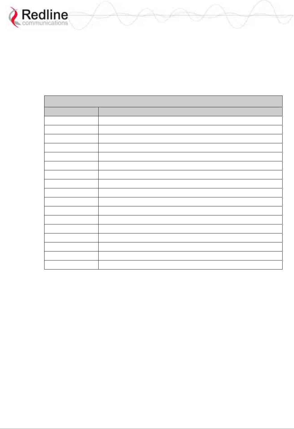
The following CLI commands are common to all configuration modes.
Table 6: CLI - Root Mode Commands
Command Description
?
Use the '?' character as an alternative to typing 'help <ENTER>'.
Example: Enter the following command string to list all parameters that
can be changed using the 'set' command:
set ?
Exit Return to root mode.
help Type 'help' alone to display the available commands. Type a
command followed by 'help' to display a command set.
help <ENTER> Help for all functions/fields.
[field] help <ENTER> Help for only the selected
function/field.
logout Exit the current Telnet session.
collectRadio Factory test only.
reboot Reset the system. Confirmation is required.
shell Factory test only.
CTRL-Z Return to root mode.
RedMAX™ Subscriber Modem
SU-O User Manual
70-00057-01-01-DRAFT Proprietary Redline Communications © 2007 September 7, 2007
Page 28 of 55
4.3 Mode Commands
The system defaults to root mode when you login to the subscriber. The following table
lists commands that have their own mode. From each mode, you can directly display and
modify (if applicable) each of the modes parameters. Enter 'exit' or CTRL-Z to return to
root mode. All commands are case-sensitive.
The following table lists mode commands available from the root directory.
Table 7: CLI - Root Mode Commands
Command Description
boardConfig Display/modify the board parameter configuration.
bsIdTable Access the Management Base Station ID table.
diagStatistics Display/modify the Diagnostic Status.
ethTag Display/modify the Ethernet Tagging.
installedVer Display the installed software version(s).
ipAddress Display/modify the IP address.
loadImage Download and run a new software image.
modThresh Display/modify thresholds for adaptive modulation.
monitor Display dynamically updating values for all status table statistics.
phyConfig Display/modify the PHY configuration.
privacySS Display/modify privacy settings.
reset Display/modify reset settings.
rfConfig Display /modify the RF configuration.
set Enter a new values for parameters.
show Display current parameter settings.
softwareUpgrade Upgrade software and select the active version.
status Display the Management Status.

RedMAX™ Subscriber Modem
SU-O User Manual
70-00057-01-01-DRAFT Proprietary Redline Communications © 2007 September 7, 2007
Page 29 of 55
4.3.1 boardConfig - Board Setup Commands
The boardConfig mode allows you to view and modify the subscriber board level
settings. The following table lists all commands available in this mode.
Table 8: CLI - boardConfig - Board Commands
Command Description
reset Set all parameters to factory default values. Confirmation required.
set Change parameter settings.
RefOscFreq: Enter an unsigned integer as the new RefOscFreq value
(Hz). Value can be only 32000000 or 40000000.
TxIfFreq: Enter the TxIfFreq (Hz) value (around 44000000).
RxIfFreq: Enter the RxIfFreq (Hz) value (around 44000000).
RfType: Enter an unsigned char as the new RfType value. One of:
0 - None
1 - Radia 3.5 GHz
2 - Radia 5.8 GHz
3 - SMI
4 - Factory Test
IfPresent: Enter an unsigned char as the new IfPresent value.
0 - Baseband only
1 - IF present
TxSpectrumInv: Enter a boolean as the new TxSpectrumInv value.
RxSpectrumInv: Enter a boolean as the new RxSpectrumInv value.
Buzzer: Antenna positioning buzzer.
0 - Disabled
1 - Enabled.
DebugLog: Factory debug messages.
0 - Disabled.
1- Enabled.
show Display the current setting for all parameters. For example:
Structure --- <<SS Mmgt Board Configuration Parameter>>
Transmit Receive Others
------------------------------ ------------------------------ ----------------
IfFreq: 44000000Hz IfFreq: 44000000Hz RefOscFreq: 32000000Hz
SpectrumInv: disabled(0) SpectrumInv: disabled(0) RfType: SMI(3)
IfPresent: IF_Present(1)
Buzzer: disabled(0)
DebugLog: disabled(0)
RedMAX™ Subscriber Modem
SU-O User Manual
70-00057-01-01-DRAFT Proprietary Redline Communications © 2007 September 7, 2007
Page 30 of 55
4.3.2 bsIdTable - Base Station ID Table Commands
The bsIdTable includes the MAC addresses of up to sixteen base stations. The subscriber
is authorized to register with any base station listed in this table. The count value
indicates the number of valid entries in the table (beginning at ID0).
When the subscriber is performing a frequency scan, the scan will be stopped
immediately if any base station listed in the bsIdTable is detected. If subscriber is
attempting to re-register, selection priority is based on table position (ID0 is highest).
Table 9: CLI - bsIdTable - Base Station ID Commands
Command Description
add Add or modify a base station ID entry. The count value will be adjusted to
reflect the current number of effective entries. If the table position value is
not specified, the entry will be made following the last valid entry.
BsId: The new entry of BsId value
EntryNumber: The entry position in the table.
Example: Enter the following command string to register a base station ID
in table position #7:
add 00:09:02:00:a3:5d [Enter]
delete Delete a base station ID entry. The count value will be adjusted to reflect
the current number of effective entries. If the table position value is not
specified, the last valid entry in the table is deleted.
EntryNumber: The entry position in the table.
show Display the base station ID table entries. If the table position value is not
specified, all entries in the table are displayed. If the keyword 'monitor' is
used, the display is updated continually.
EntryNumber: The entry position in the table.
Monitor: Dynamically updated display of table values.
Notes:
1. The detected BS table is automatically reset at the first restart after either the
frequency range table, the BS ID table or the bandwidth is modified.
2. New “Detected BS table reset” log message generated when any of the modifications
described above occur.
3. New “Add detected BS…” log message added any time a new BS is added to the
table during the initial scan process.

RedMAX™ Subscriber Modem
SU-O User Manual
70-00057-01-01-DRAFT Proprietary Redline Communications © 2007 September 7, 2007
Page 31 of 55
4.3.3 diagStatistics - Diagnostic Statistics
Use the Diagnostic Statistics commands to monitor specific operations for the subscriber.
The following table lists all commands available in this mode.
Table 10: CLI - diagStatistics - Diagnostic Statistics Commands
Command Description
list Display the current values for all statistics.
TxPowerMin: Minimum transmit power level used.
TxPowerMax: Maximum transmit power level used.
TxPowerAvg: Average transmit power level used.
DlModCodeMin: Minimum downlink coding value used.
DlModCodeMax: Maximum downlink coding value used.
DlModCodeAvg: Average downlink coding value used.
UlModCodeMin: Minimum uplink coding value used.
UlModCodeMax: Maximum uplink coding value used.
UlModCodeAvg: Average uplink coding value used.
CinrMin: Minimum measured CINR value.
CinrMax: Maximum measured CINR value.
CinrAvg: Average measured CINR value.
PhyRssiMin: Minimum measured RSSI value (physical layer).
PhyRssiMax: Maximum measured RSSI value (physical layer).
PhyRssiAvg: Average measured RSSI value (physical layer).
RfRssiMin: Minimum measured RSSI value (radio).
RfRssiMax: Maximum measured RSSI value (radio).
RfRssiAvg: Average measured RSSI value (radio).
CableCompMin: Minimum cable compensation value used.
CableCompMax: Maximum cable compensation value used.
CableCompAvg: Average cable compensation value used.
FreqOffsetMin: Minimum frequency offset used.
FreqOffsetMax: Maximum frequency offset used.
FreqOffsetAvg: Average frequency offset used.
MacResets: Number of times MAC layer has been reset.
CRCErrors: Number for CRC errors detected.
HeaderErrors: Number for packet header errors detected.
DlSdus: Number of downlink SDUs received.
DlMpdus: Number of downlink PDUs received.
UlSdus: Number of uplink SDUs sent.
UlMpdus: Number of uplink PDUs sent.
tx: Show transmit group of statistics.
dl: Show downlink group of statistics.
ul: Show uplink group of statistics.
cinr: Show CINR group of statistics.
phy: Show PHY group of statistics.
rf: Show RF group of statistics.
cable: Show Cable Compensation group of statistics.
freq: Show Frequency Offset group of statistics.
other: Show Others group of statistics.
reset Set all parameters to the last measured value. Can also be applied to
groups of statistics (i.e., tx group).

RedMAX™ Subscriber Modem
SU-O User Manual
70-00057-01-01-DRAFT Proprietary Redline Communications © 2007 September 7, 2007
Page 32 of 55
Table 10: CLI - diagStatistics - Diagnostic Statistics Commands
show Display the current setting for all parameters. For example:
Structure --- <<SS Diagnostic Statistics>>
Transmit Downlink General Uplink General CINR
--------------------- --------------------- --------------------- ---------------------
PowerMin:...-4.1 dBm ModCodeMin:....6 ModCodeMin:....6 Min:.....30.5 dB
PowerMax:...-4.1 dBm ModCodeMax:....6 ModCodeMax:....6 Max:...38.3 dB
PowerAvg:...-4.1 dBm ModCodeAvg:....6 ModCodeAvg:....6 Avg:.....34.5 dB
Sdus:........116 Sdus:.........51
Mpdus:.......516 Mpdus:........68
PHY RF Cable Compensation Frequency Offset
--------------------- --------------------- --------------------- ---------------------
RssiMin:...-16.8 dB RssiMin:...-49.6 dB CompMin:.......0 OffsetMin:....-1
RssiMax:...-15.8 dB RssiMax:...-48.6 dB CompMax:.......0 OffsetMax:..4
RssiAvg:...-16.2 dB RssiAvg:...-49.0 dB CompAvg:.......0 OffsetAvg:....0
RxCalStatus:...1
TxCalStatus:...1
Others
---------------------
MacResets:.....0
CRCErrors:.....0
HeaderErrors:..0

RedMAX™ Subscriber Modem
SU-O User Manual
70-00057-01-01-DRAFT Proprietary Redline Communications © 2007 September 7, 2007
Page 33 of 55
4.3.4 ethTag - Ethernet Tagging
Use these commands to identify data traffic through this subscriber by using 802.1Q
VLAN tags. The following table lists all commands available in this mode.
Table 11: CLI - ethTag - Ethernet Tagging Commands
Command Description
reset Set all ethTag parameters to factory default values.
set Change parameter settings.
Active:
0: Disabled - All ethTag features are disabled.
1: Enabled - Each upstream packet received on the subscriber
Ethernet port is tagged with the specified VID (value field). If the
packet has an existing VLAN tag, a new outermost tag is added (Q in
Q). The modified packet is then forwarded over the wireless interface
to the base station.
FilterOn:
0: Disabled - All packets are forwarded unmodified.
1: Enabled - All downlink packets are classified according to the
outermost VLAN tag. Packets with a VLAN tag matching the Value
field have the VLAN tag removed and are then forwarded to the
subscriber Ethernet port. All non-matching packets are discarded.
Priority: Enter the priority to be assigned to each VLAN tagged
packet to be sent over the wireless interface (uplink) to the sector
controller.
PriorityCopy:
0: Disabled - The Priority field value is inserted into the VLAN tags.
1: Enabled - If the received packet has a VLAN tag, the tags priority
value is copied to the new VLAN tag being added (Q in Q), otherwise,
the Priority field value is used.
Value: Enter the VLAN ID. This is the VLAN tag added to uplink
packets (active=1), and used to filter downlink packets (FilterOn=1).
show Display the current setting for all parameters. For example:
Structure --- <<SS Ethernet Tagging Data>>
Active:.............inactive(0)
Priority:...........0
FilterOn:.........0
PriorityCopy...0
Value:............0
Note: The base station passes all ingress and egress traffic without modification.

RedMAX™ Subscriber Modem
SU-O User Manual
70-00057-01-01-DRAFT Proprietary Redline Communications © 2007 September 7, 2007
Page 34 of 55
4.3.5 installedVer - Installed Version
Use the installed version command to view information about the binary files saved in the
subscriber non-volatile RAM, and to select the active version of software. See also
installedVer, loadImage, and version commands. The following table lists all commands
available in this mode.
Table 12: CLI - installedVer - Installed Version Commands
Command Description
set Switch the active version of image.
Active - Load the binary file from the selected partition:
0 - Load from partition #0.
1 - Load from partition #1.
show Display the current setting for all parameters.
Partition #0:
MajorNumber: Major software release number.
MinorNumber: Minor software release number.
ReleaseNumber: Software release build number.
Designation: Software release designation.
Partition #1:
MajorNumber: Major software release number.
MinorNumber: Minor software release number.
ReleaseNumber: Software release build number.
Designation: Software release designation.
Active: Indicate the active partition.
0: Partition 0 will be loaded at reboot.
1: Partition 0 will be loaded at reboot.
For example:
Partition #0 Partition #1 Others
------------------------ ------------------------ ------------------------
MajorNumber:......1 MajorNumber:......1 Active:...........1
MinorNumber:......0 MinorNumber:......0
ReleaseNumber:..100 ReleaseNumber:...98
Designation:......1 Designation:......1
RedMAX™ Subscriber Modem
SU-O User Manual
70-00057-01-01-DRAFT Proprietary Redline Communications © 2007 September 7, 2007
Page 35 of 55
4.3.6 ipAddress - IP Address Commands
Use the IP address commands to display network address settings and modify subscriber
IP address settings. The following table lists all commands available in this mode.
Table 13: CLI - ipAddress - IP Address Commands
Command Description
set Change IP address parameter settings.
Address: IP address assigned to subscriber. Static address only.
Mask: 255.255.255.0
Example: Use the following command to set a static IP address and
mask: set Address 192.168.20.33 Mask 255.255.255.0
show Display the current IP address settings. For example:
Structure --- <<SS IP Address Data>>
Address:............192.168.25.100
Mask:...............255.255.255.0
reset Reset the IP address to factory default. Requires confirmation.
Local Ethernet Port (Secondary Management) IP
All factory-shipped subscriber systems have the following IP addresses assigned to the
local Ethernet port:
Fixed: 192.168.101.1 (well-known, can not be modified)
Default: 192.168.101.2 (can be modified using CLI)
Over-the Air (Secondary Management) IP
When a subscriber is enabled for remote management (managedSS=1) its over-the-air
secondary management IP address can be assigned only through the base station acting as
a DHCP relay agent. The DHCP server and a Time-of-Day (ToD) server (specified in the
obtained lease) must be located on the network connected to the base station Ethernet
port. The subscriber can not use any DHCP or ToD server on the network connected
directly to the subscriber Ethernet port.
The DHCP exchange includes a request for the address of a ToD server, and the time
offset (option 2) specifying the time zone where the subscriber is operating (seconds from
GMT). After the subscriber acquires a DHCP lease time, it attempts to contact the ToD
server. If successful, the subscriber updates the system clock with the received time. If a
ToD server cannot be reached the subscriber initializes its system clock to the default
time of midnight January 1, 1970 GMT.
DHCP Issues
The subscriber does not keep a record of the previously assigned IP, and the IP request
field is empty during its initial request. If the lease has expired since the last time the
subscriber requested an address the DHCP server may assign a new IP address. You can
ensure that your subscriber will always receive the same IP by 1) making the lease
timeout indefinite, or 2) creating a static address reservation for your subscriber (if your
DHCP server supports these features).

RedMAX™ Subscriber Modem
SU-O User Manual
70-00057-01-01-DRAFT Proprietary Redline Communications © 2007 September 7, 2007
Page 36 of 55
4.3.7 loadImage - Download and Activate Software Image
The loadImage command can be used to update the subscriber using the SMC channel
over-the-air or the local Ethernet connection at the subscriber.
The following provides and example update session. The subscriber will reboot using the
new image automatically following a successful download.
Example Download Dialog with Subscriber
Login: admin
Password:
admin, welcome to the SS CLI. (Version 0.3)
SUO#> loadImage
Server IP Address: [enter ftp server IP address here]
File Name: [enter binary file name here]
Opening FTP connection.....Done
Downloading image
............................................................................................………………
Done
Programming update........Done
Erasing setup partition. Done.
Writing setup partition. Done.
Erasing boot block. Done
Programming boot block. Done
Flash programming complete.
SUO#>reboot

RedMAX™ Subscriber Modem
SU-O User Manual
70-00057-01-01-DRAFT Proprietary Redline Communications © 2007 September 7, 2007
Page 37 of 55
4.3.8 modThresh - Modulation Threshold
Use the modulation threshold commands to view and adjust the settings for adaptive
modulation. These setting are made at the factory and should only be adjusted by
experienced personnel. The following table lists all commands available in this mode.
Table 14: CLI - modThresh - Modulation Threshold Commands
Command Description
reset Set all parameters to factory default values. Requires confirmation.
set Change parameter settings.
Rate1Exit: RW Rate 1 exit threshold. Value > 0
Rate1Entry: RW Rate 1 entry threshold. Value > Rate1Exit
Rate2Exit: RW Rate 2 exit threshold. Value > Rate1Entry
Rate2Entry: RW Rate 2 entry threshold. Value > Rate2Exit
Rate3Exit: RW Rate 3 exit threshold. Value > Rate2Entry
Rate3Entry: RW Rate 3 entry threshold. Value > Rate3Exit
Rate4Exit: RW Rate 4 exit threshold. Value > Rate3Entry
Rate4Entry: RW Rate 4 entry threshold. Value > Rate4Exit
Rate5Exit: RW Rate 5 exit threshold. Value > Rate4Entry
Rate5Entry: RW Rate 5 entry threshold. Value > Rate5Exit
Rate6Exit: RW Rate 6 exit threshold. Value > Rate5Entry
Rate6Entry: RW Rate 6 entry threshold. Value > Rate5Exit
show Display the current setting for all parameters. For example:
Structure --- <<Modulation Rate Threshold Parameters>>
Rate1Exit:..........9.50 dB
Rate1Entry:.........10.50 dB
Rate2Exit:..........12.00 dB
Rate2Entry:.........13.00 dB
Rate3Exit:..........16.50 dB
Rate3Entry:.........17.50 dB
Rate4Exit:..........19.50 dB
Rate4Entry:.........20.50 dB
Rate5Exit:..........23.00 dB
Rate5Entry:.........24.00 dB
Rate6Exit:..........26.00 dB
Rate6Entry:.........27.00 dB

RedMAX™ Subscriber Modem
SU-O User Manual
70-00057-01-01-DRAFT Proprietary Redline Communications © 2007 September 7, 2007
Page 38 of 55
4.3.9 monitor - Monitor Mode
Use the monitor mode to view dynamically updating display for system statistics. Refer
to the status command for descriptions of each statistic.
Table 15: CLI - monitor - Monitor Mode
Command Description
View system statistics.
Rssi: Snr: FreqOffset: TCnt: ModemResets:
-16.5 31.7 -1 0 5
DlfpCount: DlfpErrCount: DlfpCrcCount: DlMapCount: DlMapErrCount:
311714 0 1 12468 0
DlMapCrcCount: UlMapCount: UlMapErrCount: UlMapCrcCount: DcdRxCount:
0 311714 0 0 1396
DcdErrCount: DcdCrcCount: UcdRxCount: UcdErrCount: UcdCrcCount:
0 0 1396 0 0
MgmtRxCount: MgmtErrCount: MgmtCrcCount: LostFrames: FrameDuration:
87 0 0 1 10000
DcdChangeCount: RngTimeCorrection DlByteCount: DlSduCount: DlMpduCount:
0 -76 56642560 60824 304083
DlHCrcErrCount: DlCrcErrCount: UlByteCount: UlSduCount: UlMpduCount:
0 0 118122579 117162 56187
TotalHCrcErrors TotalCrcErrors TotalTxBurstCnt: TotalRngReqcnt: TotalBwReqCnt:
0 0 145145 6 34917
TotalMgmSentCount: TotalPaddingCount: RfRssi: TxPower: LinkStatus:
24 135617 -49.3 -4.3 Registered(1)

RedMAX™ Subscriber Modem
SU-O User Manual
70-00057-01-01-DRAFT Proprietary Redline Communications © 2007 September 7, 2007
Page 39 of 55
4.3.10 phyConfig - Physical Layer Configuration
The phyConfig mode allows you to view and modify the subscriber physical layer (PHY)
settings. The following table lists all commands available in this mode.
Table 16: CLI - phyConfig - Physical Layer Commands
Command Description
reset Set all parameters to factory default values. Requires confirmation.
set Change physical layer parameter settings.
Bandwidth: Channel size (KHz).
Selections are: 1750, 3500, or 7000.
FftSize: OFDM fft size.
Valid settings are: 128, 256, 512, or 1024.
PsPerOFDMSymbol: Physical slots per OFDM symbol value in PS.
SmplFactorNum: Above the fraction line in the sampling factor (ns).
Normally set to 8 nsec.
SmplFactorDen: Under the fraction line in the sampling factor (ns).
Normally set to 7 nsec.
CyclicPrefix: Cyclic prefix (CP). The guard interval is used to factor
out multipath effect.
Valid settings are: 4, 8, 16, and 32. Default value for subscriber is 16
(1/16).
Example: Enter the following command string to set the channel size to 3500 KHz:
set Bandwidth 3500 [Enter]
show Display the current setting for all parameters. For example:
Structure --- <<SS Mmgt PHY Configuration Parameter>>
Bandwidth:..........3500 kHz
FftSize:............256
PsDuration:.........1000
PsPerOFDMSymbol:....68
SmplFactorNum:......8
SmplFactorDen:......7 nsec
CyclicPrefix:.......16 PS
RedMAX™ Subscriber Modem
SU-O User Manual
70-00057-01-01-DRAFT Proprietary Redline Communications © 2007 September 7, 2007
Page 40 of 55
4.3.11 privacySS - Privacy Commands
The privacySS mode allows you to view and modify the privacy settings for the
subscriber. The following table lists all commands available in this mode.
Table 17: CLI - privacySS - Privacy Commands
Command Description
set Change privacy related settings on subscriber. All times are in seconds.
Enable:
0 -- Disable privacy.
1 -- Enable privacy.
UseTestTimers:
0 -- Use programmed timers
1-- Use test defaults.
show Display privacy related settings on subscriber. For example:
Structure --- <<SS privacy Data>>
Enabled:............Disabled(0)
UseTestTimers:......Normal(0)
AuthWaitTime:.......10
ReauthWaitTime:.....10
AuthGraceTime:......600
OperationalWaitTime:1
RekeyWaitTime:......1
TekGraceTime:.......3600
AuthRejectWaitTime:.60
4.3.12 reset - Reset Command
The reset command is allows you to set parameters to factory default values. The
following table lists all commands available in this mode.
Table 18: CLI - reset - Reset Commands
Command Description
detectedBS Clear all entries and associated settings from the detectedBS table.

RedMAX™ Subscriber Modem
SU-O User Manual
70-00057-01-01-DRAFT Proprietary Redline Communications © 2007 September 7, 2007
Page 41 of 55
4.3.13 rfConfig - RF Setup Commands
The rfConfig mode allows you to view and modify the subscriber RF settings. The
following table lists all commands available in this mode.
Important: The subscriber must be rebooted before changes to the rfConfig frequency
settings become effective
Table 19: CLI - rfConfig - Radio Frequency Commands
Command Description
reset Reset all RF parameters to factory default values. Requires confirmation.
set Modify RF parameters.
TxFixedPower: Tx Gain. Value between: -10.00 and +20.00
RxGain: Rx Gain. Value between: -19.00 and +80.00
TxFixedGain: Tx power scan during network entry
0 - Enable / 1 - Disable.
RxAgc: Receive automatic gain control AGC).
0 - Enable / 1 - Disable.
LoRfFreq1: Lower limit of the 1st Frequency Scan Interval.
HiRfFreq1: Upper limit of the 1st Frequency Scan Interval.
LoRfFreq2: Lower limit of the 2nd Frequency Scan Interval.
HiRfFreq2: Upper limit of the 2nd Frequency Scan Interval.
LoRfFreq3: Lower limit of the 3rd Frequency Scan Interval.
HiRfFreq3: Upper limit of the 3rd Frequency Scan Interval.
LoRfFreq4: Lower limit of the 4th Frequency Scan Interval.
HiRfFreq4: Upper limit of the 4th Frequency Scan Interval.
LoRfFreq5: Lower limit of the 5th Frequency Scan Interval.
HiRfFreq5: Upper limit of the 5th Frequency Scan Interval.
LoRfFreq6: Lower limit of the 6th Frequency Scan Interval.
HiRfFreq6: Upper limit of the 6th Frequency Scan Interval.
show Show the current setting for all parameters.
Frequency Scanning
Scanning ranges must not intersect or overlap. When changing settings, the order of data
entry must ensure the 'Hi' setting is always greater than the 'Lo' setting. For example,
when changing from the default setting 'Hi=0, Lo=0' you must enter the Hi setting first.
The subscriber always performs a frequency scan at power-on or reboot. Scanning is
performed using 250 KHz steps, monitoring each step for approximately one second. If
there are no bsIdTable entries at power-on/reboot, the subscriber will always complete
the entire scan for all entered ranges. Unlisted base stations are added to the bsIdTable in
order based on signal level (CINR). When the scan is completed, the subscriber will
attempt to register with the base station having the best signal quality. If no base stations
were detected, or the subscriber is unable to register with any detected base station, the
scan is repeated.
If bsIdTable entries exist at power-on/reboot, the scan is stopped immediately when any
base station listed in the bsIdTable is detected, and the subscriber will attempt to register
with that base station. If the subscriber is unable to register with any detected base
station, the scan is repeated.
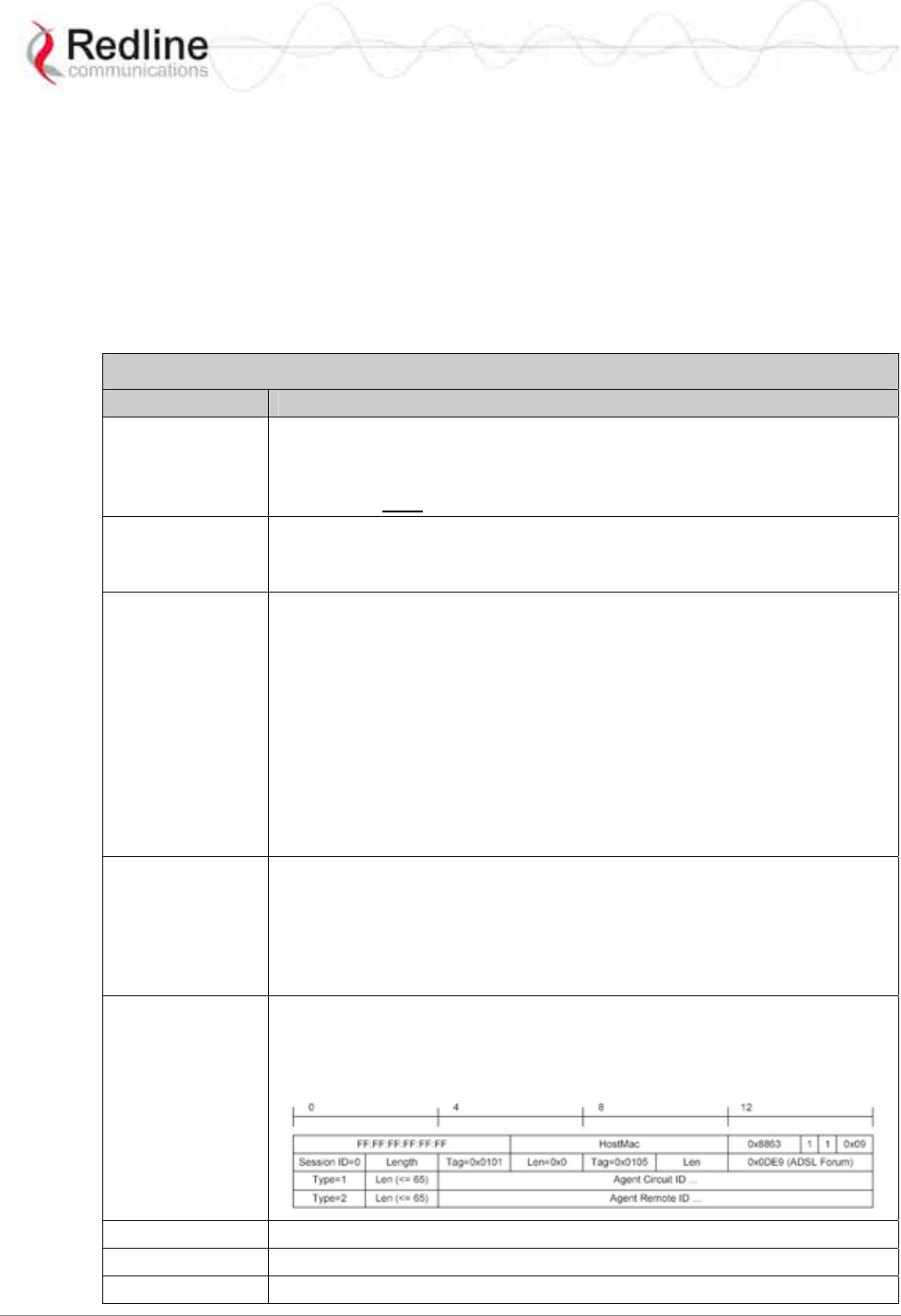
RedMAX™ Subscriber Modem
SU-O User Manual
70-00057-01-01-DRAFT Proprietary Redline Communications © 2007 September 7, 2007
Page 42 of 55
4.3.14 set - Set Commands
The set mode can be used to directly modify all available subscriber parameters. The
parameters listed in this table do not have a separate mode, and can openly be modified
by the set command.
Enter a new value for one or more fields in mode.
set [Enter] Display all fields.
Modify selected field(s).
set [mode] [field] [value] [value] [field] […] <ENTER>
Table 20: CLI - set - Modify Subscriber Parameters
Command Description
dhcpRelayAgent Use this setting to enable or disable the DHCP relay setting.
0 -- Disable DHCP relay agent.
1 -- Enable DHCP relay agent.
This feature must be enabled to use DHCP Option 82.
dlLearnFilter Use this setting to enable or disable the DHCP relay setting.
0 -- Disable filter - Do not filter DL packets.
1 -- Enable filter - Only forward DL packets based on learned hosts.
ethernet Use this setting to modify the Ethernet port auto negotiation, link speed,
and duplex settings.
AutoNegEnabled <value>
0 -- Disabled
1 -- Enabled.
LinkSpeed <value>
0 -- 10M
1 -- 100M.
LinkDuplex <value>
0 -- Half
1 -- Full.
managedSS The managedSS command allows you to configure the subscriber for
independent operation, or enable management using the RedMAX EMS
system. The managedSS parameter is controlled from root mode. The
following table lists all commands available for managedSS.
0 - Disable remote management
1 - Enable remote management
pppoe Enable/Disable DSL Forum VSA in PPPoE Vendor-Specific Tag
(RFC4679).
0 - Disable pppoe
1 - Enable pppoe
sysContact Enter device administration contact information (255 chars max.).
sysLocation Enter the device location (255 characters max.).
sysName Enter the device name (255 characters max.).
RedMAX™ Subscriber Modem
SU-O User Manual
70-00057-01-01-DRAFT Proprietary Redline Communications © 2007 September 7, 2007
Page 43 of 55
4.3.15 show - Show Commands
The fields in this section are available only by using the show command. The following
table lists all functions available in this mode.
Table 21: CLI - show - Show Commands
Command Description
dhcpRelayAgent Show the SS DHCP Relay Agent setting.
0 - Disabled
1 - Enabled
detectedBS Show details for detected base stations. Including frequency and
CINR. For example:
<< Detected BSID Table >>
0) ........ 00:09:02:00:a3:5d Freq 3424000 kHz Cinr 305 dBm
ethernet Display the Ethernet port settings:
AutoNegEnabled - Auto Negotiation (Disabled/Enabled)
LinkSpeed - Link Speed (10/100)
LinkDuplex - Link Duplex (half/full)
eventLog Display the event log messages.
interfaces Display information about the subscriber wireless and Ethernet
interfaces. For example:
ifIndex Desc MAC Address ifAdminStatus ifType ifMtu
------- ------- -------------------- ------------------- --------- ------
1 802.16 00:09:02:00:8c:7f 1 184 2048
2 802.3 00:09:02:00:8c:7f 1 6 1500
sysContact Display the system contact information.
sysDescr Display the system contact information.
sysLocation Display system location string. For example:
sysLocation: 123 Mains St. Unit #12
sysname Display the system name.
sysUpTime Display system up time. For example:
sysUpTime: 10 days 20:28:19
version Display the currently running software version.

RedMAX™ Subscriber Modem
SU-O User Manual
70-00057-01-01-DRAFT Proprietary Redline Communications © 2007 September 7, 2007
Page 44 of 55
4.3.16 softwareUpdate - Software Update Commands
Use the softwareUpdate commands to display the software versions stored in the
subscriber non-volatile memory, download software updates from an FTP server, and
switch the active versions.
Table 22: CLI - softwareUpdate - Software Update Commands
loadImage Download software binary file and save in non-volatile memory
(inactive partition). Following download, you must enter the
reboot command to run the new software. On the next reboot
following a successful download, the subscriber will
automatically switch active partitions and run the downloaded
file.
show Display software version information for downloaded binary files.
Indicates the active version.
switch Switch to the currently inactive software version. Confirmation is
required. The subscriber will be rebooted. This is done
automatically following a successful file download.
sync Synchronize the binary files saved in the active and inactive
partitions. This command copies the 'active' binary file into the
inactive partition. Following execution of this command, both
partitions (#0 and #1) will contain identical software versions.
For example:
SUO#> loadImage
Server IP Address: 192.168.101.102
File Name: SUO-U1-001-01-00-078.bin
Opening FTP connection.....
DoneDownloading image
............................................................................................……………………
............................................................................................……………………
........................................................................................
DoneProgramming update........
DoneErasing setup partition.
Done.Writing setup partition.
Done.Erasing boot block.
DoneProgramming boot block.
DoneFlash programming complete.
SUO#>reboot

RedMAX™ Subscriber Modem
SU-O User Manual
70-00057-01-01-DRAFT Proprietary Redline Communications © 2007 September 7, 2007
Page 45 of 55
4.3.17 status - Status Information
The status mode allows you to view general subscriber statistics. The following table lists
all commands available in this mode.
Table 23: CLI - status - Status Commands
Command Description
reset Set all parameters to factory default values.
show Display the current setting for all parameters.
DlfpCount: Downlink FPs (frames) received.
DlfpErrCount: Downlink FP semantic errors.
DlfpCrcCount: Downlink FP messages with CRC errors.
DlMapCount: Downlink MAP messages.
DlMapErrCount: Downlink MAP semantic errors.
DlMapCrcCount: Downlink MAP messages with CRC errors.
DlByteCount: Downlink Bytes received.
DlSduCount: Downlink SDUs received.
DlMpduCount: Downlink MPDUs received.
DlHCrcErrCount: Downlink data HCRC errors.
UlMapCount: Uplink MAP messages.
UlMapErrCount: Uplink Invalid MAP messages.
UlMapCrcCount: Uplink MAP messages with CRC errors.
UlByteCount: Uplink Bytes received.
UlSduCount: Uplink SDUs received from CL
UlMpduCount: Uplink MPDUs sent.
MgmtRxCount: Total management messages.
MgmtErrCount: Invalid management messages.
MgmtCrcCount: Management messages with CRC errors.
UcdRxCount: Uplink Channel Descriptor messages.
UcdErrCount: Uplink Channel Descriptor messages that are Invalid.
UcdCrcCount: Uplink Channel Descriptor messages with CRC errors.
Rssi: Received Signal Strength Indicator.
Snr: Signal-to-Noise Ratio.
FreqOffset: Frequency Offset.
TCnt: Time count of the last burst received.
ModemResets: Number of times the modem was reset due to errors.
LostFrames: Number of logical frames lost.
FrameDuration: Duration in microseconds: 2500 to 20000.
RngTimeCorrection: Time correction from ranging response.
TotalHCrcErrors: Header CRC errors.
TotalCrcErrors: Payload CRC errors.
TotalTxBurstCount: Transmit burst.
TotalRngReqCount: Ranging requests.
TotalBwReqCount: Bandwidth requests.
TotalMgmSentCount: Management traffic sent.
TotalPaddingCount: Padding bytes sent.
RfRssi: Current RSSI value.
TxPower: Current Tx output power.
LinkStatus: Registered(1).

RedMAX™ Subscriber Modem
SU-O User Manual
70-00057-01-01-DRAFT Proprietary Redline Communications © 2007 September 7, 2007
Page 46 of 55
Chapter
5
5
5
A
Ap
pp
pe
en
nd
di
ic
ce
es
s
5.1 System Technical Specifications
Table 24: Specifications - Outdoor Wireless Subscriber Modem
System Models: SU-OIA / SU-ORF (SU-O)
System Capability: LOS, Optical LOS, non LOS
Cell-based point-to-multipoint deployment
RF Band: 3.300 GHz to 3.500 GHz (FWA Band) 1
3.400 GHz to 3.600 GHz (FWA Band) 1
3.600 GHz to 3.800 GHz (FWA Band) 1
Channel Size: 3.5, 7 MHz
RF Dynamic Range: > 45 dB
Spectral Efficiency: Up to 5 bps/Hz (over the air)
Over The Air Rate: Up to 17.5/ Mbps Uncoded Rate @ 3.5 MHz channel 2
Up to 35 Mbps Uncoded Rate @ 7 MHz channel 2
Data Rate: Up to 5 Mbps Max. Ethernet Rate @ 3.5 MHz channel 2
Up to 10 Mbps Max. Ethernet Rate @ 7 MHz channel 2
Maximum Tx Power: +20 dBm, 16 dBm for 64 QAM
Rx Sensitivity: -93 dBm @ BPSK 1/2 (3.5 MHz channel)
Cable Length (max.): SU-O-to-PoE: 76 m (250 ft) using Redline supplied
CAT-5 double shielded outdoor cable (without lightning protection)
PoE-to-Customer Equipment (using Redline-supplied PoE adapter):
2 m (6.5 ft) using customer supplied indoor CAT-5 cable.
Network Attributes: Transparent bridge, 802.1Q VLAN, 802.1p
DHCP client, DHCP pass-through
Modulation/Coding Rates: Modulation: BPSK, QPSK, 16 QAM, 64 QAM
Coding: 1/2, 2/3, 3/4
MAC: Cell-based PMP deployment @ 1 CID/subscriber:
64 subscribers per sector
802.16-2004 compliant PMP
802.16-2004 packet convergence sub-layer mode
QoS (delay, CIR/PIR)
Scheduled Services (UGS, rtPS, nrtPS, UPS, BE)
TDMA Access
Range: 20 km (13 miles) LOS
2.5 km (1.5 miles) non LOS
RedMAX™ Subscriber Modem
SU-O User Manual
70-00057-01-01-DRAFT Proprietary Redline Communications © 2007 September 7, 2007
Page 47 of 55
Table 24: Specifications - Outdoor Wireless Subscriber Modem
Duplex Technique: TDD (Time Division Duplex),
HD-FDD (Half-Duplex Frequency Division Multiplexing)
Wireless Transmission: 256 FFT Orthogonal Frequency Division Multiplexing
(OFDM)
Network Connections: RJ-45 (10/100 Ethernet) 802.30
System Configuration: Telnet CLI, FTP (software updates)
Power Requirements: PoE: Standard IEEE 802.3af
PoE Power Adaptor: Optional power adaptor: PowerDsine Model PD-3001/AC (or equiv.)
Auto-sensing 110/220/240 VAC 50/60 Hz, 10.5 W
Standards: Environmental: IEC60529 Degree of Protection IPX7, IP67
IEEE: 802.3, 802.1Q, 802.1p, 802.16-2004
Compliance: EMC: EN 301 489-1, EN 301 489-4, EN 55022/CISPR 22
Industry Canada: RSS-192
RF: EN 301 021, EN 301 753
Safety: IEC 60950-1, EN 60950-1, UL 60950-1
Operating Temperature: Outdoor Unit: -40 C to 65 C
Antenna: Integrated flat panel (14 dBi)
Optional external antennas available
Wind Loading: Antenna: 220 Km/hr (137 mph) for integrated antenna
Dimensions: 20 x 20 x 7.5 cm (8 x 8 x 2.5 in)
Weight: 2 Kg (4.5 lb) (does not include mounting bracket)
1 Frequency range dependant on installed radio option, license, and regulatory domain.
2 Actual Ethernet data throughput is dependent on channel size, protocols, packet size, burst
rate, transmission latency, and link distance.
5.2 Receive Sensitivity
The following table lists the RedMAX subscriber sensitivity levels for different
modulation and coding levels.
Table 25: Reference - RedMAX Subscriber Receive Sensitivity
Modulation Coding 3.5 MHz 7 MHz
BPSK 1/2 -96 -93
1/2 -93 -90
QPSK 3/4 -92 -89
1/2 -89 -86
16 QAM 3/4 -86 -83
2/3 -82 -79
64 QAM 3/4 -77 -74
RedMAX™ Subscriber Modem
SU-O User Manual
70-00057-01-01-DRAFT Proprietary Redline Communications © 2007 September 7, 2007
Page 48 of 55
5.3 Subscriber Log Messages
Table 26: Troubleshooting - Event Log Messages
Log Message Description
Add classifier [CID:
XXXX, Idx: nn] A classifier with the following CID has been added.
Broadcast Opportunity
Corrupted Opportunities have been received for initial ranging, but
the opportunity is not appropriate (i.e. too short) for this
subscriber.
Broadcast Ranging
Opportunity Received This message indicates that the base station has provided
an opportunity for subscriber registration.
Broadcast Ranging
Opportunity Timeout This message indicates that the base station has not
provided an opportunity for new subscriber registration
within the last 10 seconds.
Classifier deleted [Idx:
nn] The specified classifier has been deleted.
Classifiers deleted for SF
with CID XXXX All classifiers have been cleared for the specified service
flow.
DCD Receiving Timeout The subscriber has not received downlink channel
descriptors for five consecutive opportunities. The
subscriber will now restart the ranging process in an
attempt to re-establish wireless synchronization.
Deregistration DREG-
CMD, action code: nn The subscriber has de-registered.
Deregistration DREG-
CMD, action code: nn base station has requested that subscriber should
deregister.
DHCP Error There has been an error in obtaining a DHCP lease
Downlink Burst Profile
Adjusted [BP: nn] Downlink modulation rate has been adjusted by the base
station.
Downlink Burst Profile
Change Attempt [BP: nn] A request to change the downlink modulation rate has
been made based on locally configured CINR thresholds.
Downlink Channel
Inoperable This message is displayed when the subscriber detects
the presence of a base station, but is unable to properly
synchronize with it.
Downlink SF nn changed Changes have been successfully applied to the specified
downlink service flow.
Downlink SF nn created
[CID: XXXX, No.Cls: nn] A downlink service flow has been successfully created.
Downlink SF nn not
created (no space) [CID:
XXXX]
The subscriber cannot create the specified DL service
flow, as there is not enough remaining memory.
DSA Err - DSA-ACK send
retries exhausted [SF Id:
XXXX]
subscriber has attempted to acknowledge a DSA
transaction unsuccessfully more than the maximum
number of times.
DSA Rejected - Service
Flow exists [SF Id: XXXX]
The service flow ID assigned base station already exists
locally in subscriber
RedMAX™ Subscriber Modem
SU-O User Manual
70-00057-01-01-DRAFT Proprietary Redline Communications © 2007 September 7, 2007
Page 49 of 55
Table 26: Troubleshooting - Event Log Messages
Log Message Description
DSC abort by DSC-ACK
[SF Id: XXXX] A DSC transaction has been aborted due to an
acknowledgement message not being received by the
subscriber.
DSC Err - DSC-ACK
send retries exhausts [SF
Id: XXXX]
subscriber has attempted to acknowledge a DSC
transaction unsuccessfully more than the maximum
number of times.
DSC Err - DSC-RSP
send retries exhausts [SF
Id: XXXX]
subscriber has attempted to acknowledge a DSC-RSP
transaction message unsuccessfully more than the
maximum number of times.
DSC Err - SF or CLS
rejected [SF Id: XXXX] DSC transaction has been rejected by base station.
DSC Success [SF Id:
XXXX] DSC transaction has been successful.
DSC-DSD Reject - SF ID
not found base station has requested the deletion of a SFID which
does not exist.
DSD Success [SF Id:
XXXX] DSD transaction has successfully completed.
DSx Action [error]
There has been an error in the creation of a service flow.
The particular failure is detailed in the message text.
DSx Add Reject [reason]
This message signifies that the addition of a service flow
has been rejected by the subscriber. The reason for the
failure is included in the message text.
Failed to acquire the
time-of-day Communication with a ToD (RFC-868) server has not
been successful. The correct time of day has not been
acquired. According to standard, the subscriber must now
perform a MAC reboot and begin network entry again.
Initial Ranging at
Maximum Power [Adj.:
+nn]
subscriber has begun initial ranging with a base station,
and has reached its maximum Tx power while attempting
to establish communication.
Initial Ranging at
Minimum Power [Adj.:
+nn]
subscriber has begun initial ranging with a base station,
and has reached its minimum Tx power while attempting
to establish communication.
Initial Ranging Backoff A contention was encountered with another subscriber
while attempting to perform initial ranging. The subscriber
will wait and try again after the backoff interval.
Initial Ranging
Parameters Adjusted
[TLV Map: XXXXXXX]
This message displays the parameter adjustments as
requested by the base station.
Initial Ranging Success
[TLV Map: XXXXXXX] Initial ranging has been completed successfully.
Invalid MAC address This message is displayed when the MAC of the
subscriber does not belong the Redline. The system will
not function in this state.
Large Time Adjustment
Received An excessively large timing correction has been sent by
the base station. This correction has not been applied,
though it has been acknowledged.
RedMAX™ Subscriber Modem
SU-O User Manual
70-00057-01-01-DRAFT Proprietary Redline Communications © 2007 September 7, 2007
Page 50 of 55
Table 26: Troubleshooting - Event Log Messages
Log Message Description
Lost DL-MAP The time since the last valid DL MAP was received by the
subscriber has exceeded the timeout. The subscriber will
now begin the ranging process in an attempt to re-
establish wireless synchronization.
Lost UL-MAP The time since the last valid UL MAP was received by the
subscriber has exceeded the timeout. The subscriber will
now begin the ranging process in an attempt to re-
establish wireless synchronization.
MAC Initialized The MAC processor has completed initialization.
MAC Reset:
Configuration Change The MAC has required a reset to apply a configuration
change that was made by the user.
MAC Reset: SC Request
(RES-CMD) The base station has requested that the subscriber reset
its MAC.
MAC Reset: SC Request
(RES-CMD) base station has requested that subscriber should reset its
MAC.
MAC Started The MAC processor has been started.
New Cls for SF with CID
XXXX A new classifier has been added to the specified service
flow.
No Maintenance Data
Grant Slot T4 IF subscriber has nothing to send, the base station should
grant unsolicited bandwidth. subscriber should respond
with padding. This message indicates that the base station
has not granted this data for 35 seconds.
REG Failure - Retries
Exhausted The timer above (T6) has been hit 3 times in a row. The
subscriber will now reboot and begin scanning for a base
station again.
REG Success [TLV Map:
XXXXXXXX] The subscriber has successfully registered.
REG Wait Timeout T6 [nn
retries] The subscriber has not received a response to its
registration request within 3 seconds.
REG_REQ authentication
failure - HMAC [CC: nn] With privacy enabled, authentication failed.
REG-REQ not sent - no
bw granted The subscriber has not been able to send a registration
request message to the base station, since the base
station has not granted it bandwidth to do so. It cannot
request bandwidth, because it is not yet registered.
Reset [reason]
The subscriber has reset itself. The reason for the reset is
included in the message text.
Rf Rx Calibration Error Rx Calibration data located in the subscriber’s EEPROM
has failed CRC
Rf Tx Calibration Error Tx calibration data located in the subscriber’s EEPROM
has failed CRC
Rng Maintenance
Correction Anomaly [TLV
Map: XXXXXXXX]
An adjustment requested by the base station has failed.
Not a fatal error.
Rng Maintenance
Correction Success [TLV
Map: XXXXXXXX]
An adjustment requested by the base station has been
successfully applied.
RedMAX™ Subscriber Modem
SU-O User Manual
70-00057-01-01-DRAFT Proprietary Redline Communications © 2007 September 7, 2007
Page 51 of 55
Table 26: Troubleshooting - Event Log Messages
Log Message Description
SBC Failure - Retries
Exhausted T18 expired beyond the maximum number of allowed
retries.
SBC Success [TLV Map:
XXXXXXXX] The subscriber has successfully negotiated its basic
capabilities with the base station.
SBC Wait Timeout T18
[nn retries] A SBC request response is not received within 50ms.
SBC-REQ not sent - no
BW granted base station has not allocated bandwidth to allow
subscriber to do SBC and registration
Synchronization
Completed The subscriber has completed scanning for a downlink
channel, and established synchronization with a base
station. It will now begin its initial ranging process.
System startup [status]
The subscriber has begun the bootup sequence. The
startup status will be included in the text of this message.
Modes specify a possible reason for reboot.
TFTP - no response T26
[nn retries] SMC setup has not completed within the allowed time.
TFTP Completed
Successfully This message confirms that SMC registration has
completed. Communication with DHCP and ToD servers
was successful.
TFTP Success SMC IP, ToD, have been successfully obtained via DHCP.
TFTPC failed send SMC has failed, and the subscriber will reset the MAC and
begin registration process again.
Time-of-day acquired Communication with a ToD (RFC-868) server has been
successful. The correct time of day has been acquired.
UCD Receiving Timeout 5 uplink channel descriptors in a row have been expected
and not received. The subscriber will now restart the
ranging process in an attempt to re-establish wireless
synchronization.
Unicast Initial Ranging
No Response T3 [nn
retries]
The base station has not responded to an initial ranging
request sent by the subscriber within 200 ms.
Unicast Initial Ranging
Retries Exhausted [nn
retries]
The subscriber has attempted to perform initial ranging 16
times and has failed each time.
Unicast Initial Ranging
Start [CID: XXXX] The subscriber has received a unicast ranging opportunity
Unicast Ranging Abort Indicates that the base station has sent the subscriber a
ranging abort, telling it to halt the ranging process.
Uplink Channel
Parameters Acquired The subscriber has successfully obtained the uplink
channel descriptor
Uplink SF nn changed Changes have been successfully applied to the specified
uplink service flow.
Uplink SF nn created
[CID: XXXX, No.Cls: nn] An uplink service flow has been successfully created.
Uplink SF nn not created
(no space) [CID: XXXX] The subscriber cannot create the specified UL service
flow, as there is not enough remaining memory.

RedMAX™ Subscriber Modem
SU-O User Manual
70-00057-01-01-DRAFT Proprietary Redline Communications © 2007 September 7, 2007
Page 52 of 55
5.4 Upgrade Subscriber
Use the following procedures for all RedMAX subscribers.
Very Important!
Do not reset or remove power from the SU-O units immediately after rebooting the
upgraded SU-O. The software upgrade may require a minimum of two minutes to
complete the re-programming. If the upgrade process is interrupted by a reboot or
power-cycle, the SU-O may become unmanageable and require that these units be
returned to the factory for reprogramming.
The following procedures describe manually updating the base station and subscribers.
The subscribers must be updated using CLI while the base station may be updated using
CLI or the Web interface. If available, you may use the RedMAX RMS server
provisioning features to upgrade the RedMAX software. All upgrades require an FTP
server.
Important: Upgrades should be performed during scheduled outage periods.
Subscribers may be offline for up to 15 minutes when the sector controller is rebooted.
5.4.1 FTP Server
An FTP server is required for all upgrades. The FTP server must be located on the
network connected to an active Ethernet port (Data or Mgmt) on the base station. The
following items must be addressed before beginning software upgrades:
1. You must obtain the correct versions of the base station and subscriber binary files.
2. The base station and subscriber perform all software upgrades using an FTP server:
a) You must copy the base station and subscriber binary files into the default
file location for the FTP server (you can not specify a 'path' in the upgrade
dialog).
b) The FTP server must have a user defined as follows:
Username: target
Password: secret
5.4.2 Upgrade Path
Refer to the RedMAX release notes to determine the correct software upgrade path.
5.4.3 Connection to Subscriber
If performing the upgrade using the local Ethernet port, it is important to use the correct
cables and connections when updating the subscriber.
Subscriber PoE Power Adapter Caution:
Warning to Service Personnel: 48 VDC
Standard Ethernet equipment may be damaged if connected directly to the 'Data + Power
Output' port of a PoE power adaptor.

RedMAX™ Subscriber Modem
SU-O User Manual
70-00057-01-01-DRAFT Proprietary Redline Communications © 2007 September 7, 2007
Page 53 of 55
5.4.4 Update Software Procedure
1. Start a telnet session to the subscriber using the following settings:
Login: admin
Password: admin
2. Enter the 'loadImage' command. The subscriber will prompt you to enter the
following information:
Server IP address: [enter address of FTP server]
File Name: [enter binary file name- including .bin extension]
3. The subscriber performs FTP server authentication with user name 'target' and
password 'secret' (these settings cannot be altered). The image will be uploaded to the
subscriber and saved in the non-volatile memory (flash).
4. The subscriber must be rebooted to load the new software. Enter the 'reboot'
command to reset the unit. The telnet session will be terminated.
Example Download Dialog with Subscriber
Login: admin
Password:
admin, welcome to the SS CLI. (Version 0.3)
SUO#> loadImage
Server IP Address: [enter ftp server IP address here]
File Name: [enter binary file name here]
Opening FTP connection.....Done
Downloading image
............................................................................................………………
Done
Programming update........Done
Erasing setup partition. Done.
Writing setup partition. Done.
Erasing boot block. Done
Programming boot block. Done
Flash programming complete.
SUO#>reboot

RedMAX™ Subscriber Modem
SU-O User Manual
70-00057-01-01-DRAFT Proprietary Redline Communications © 2007 September 7, 2007
Page 54 of 55

Doc #70-00057-01-01-DRAFT Proprietary Redline Communications © 2007 September 7, 2007
Page 55 of 55
302 Town Centre • Suite 100
•
Markham, Ontario
•
Canada • L3R 0E8
www.redlinecommunications.com