Remeha Avanta Plus Gas 210 Technical Information
2015-05-27
: Remeha-Avanta-Plus Remeha-Avanta-Plus-Gas-210-Technical-Information-724294 remeha-avanta-plus-gas-210-technical-information-724294 remeha-avanta-plus pdf
Open the PDF directly: View PDF ![]() .
.
Page Count: 72
114494-04
High efficiency Low NOX gas boiler
Types:
210-80
210-120
210-160
210-200
EN
English
Technical
information
GAS 210 ECO PRO

GAS 210 ECO PRO
2
114494-03
Preface 6
1. EC declaration 7
2. Introduction 8
2.1 Pictograms used 8
2.2 Important instructions 8
3. Safety 9
4. Installation 10
4.1 Scope of delivery and installation 10
4.2 Dimensions 11
4.3 Installation and service clearances 12
5. Water-side connections 13
5.1.1 Condensed water discharge 13
5.1.2 Water treatment 13
5.1.3 Pressure relief valve 14
5.1.4 Circulation pump 14
5.1.5 Water flow 14
6. Gas-side connections 15
6.1 Gas connection 15
6.2 Gas pressure 15
6.3 Gas/air ratio control 15
7. Connecting the flue gas discharge and air supply 16
7.1 General 16
7.2 Conventional open flue installation 16
7.2.1 Possible lengths for the flue gas discharge pipe 17
7.3 Room sealed installation 18
7.3.1 Possible lengths for the air supply and flue gas discharge 18
7.3.2 Discharge in different pressure areas 20
7.3.3 Connection of flue gas discharge and choice of material 21
7.3.4 Air supply connection and choice of material 21
7.3.5 Additional Directives 21
8. Control and electrical connections 22
8.1 General 22
8.1.1 Boiler control 22
8.1.2 Modulating controls general 22
8.1.3 Modulating room control 22
8.1.4 Modulating weather-compensated control rematic® 22
8.1.5 Modulating cascade controller MC4 23
8.2 Electrical specifications 23
8.2.1 Mains voltage 23
8.2.2 Control box 23
8.2.3 Fuse ratings 24
8.3 Electrical connection options 24
8.3.1 Connection options of standard control unit (PCU-01) 24
8.3.2 On/off control (OT) 24
8.3.3 Modulating controls (OT) 24
8.3.4 External interlock (BL) 24
8.3.5 Input release (RL) 25
8.3.6 Circulation pump (Pump) 25
8.3.7Connecting a PC 25
Table of contents
Table of contents

114494-03
GAS 210 ECO PRO
3
8.3.8 Connection options for the PCB - SCU - X01 25
8.4 Connection options for the optional 0 - 10 V control PCB (IF-01) 26
8.4.1 Connection status (Nc) 26
8.4.2 OTm connection 26
8.4.3 Analogue input (0 - 10 V) 27
8.4.4 Analogue output (0 - 10 V) 27
8.5 Connection options of the optional expanded control/protection PCB (SCU-S01) 28
8.5.1 Flue gas damper control (FgV) 28
8.5.2 Hydraulic valve control (HdV) 28
8.5.3 External gas valve control (EgV) 28
8.5.4 Operation signal and failure signal (Nc / No) 28
8.5.5 Water pressure sensor (Wps) 28
8.5.6 Outside temperature sensor (Tout) 29
8.5.7 Minimum gas pressure switch (Gps) 29
8.5.8 Gas leakage control (VPS; only for 210- 160 and 210- 200 boilers) 29
8.5.9 Wiring diagram 30
9 Commissioning 31
9.1 Control panel 31
9.1.1 Normal start-up procedure 31
9.1.2 Fault during start-up procedure 32
9.1.3 Reading current values 33
9.1.3.1 Status and sub status 34
9.1.4 Adjusting the boiler to the system 34
9.1.5 Changing parameters at user level (without access code) 35
9.1.6 Changing parameters at service level (with access code) 35
9.1.7 Resetting factory settings 38
9.1.8 Setting manual operation ( symbol) 39
9.2 Commissioning 39
9.3 Taking the boiler out of operation 42
9.3.1 Boiler with frost protection, out of operation for a long time 42
9.3.2 Boiler without frost protection, out of operation for a long time 42
10. Inspection and maintenance 43
10.1 General 43
10.2 Combustion check of the boiler 43
10.2.1 Corrective maintenance 43
10.2.2 Cleaning the fan 44
10.2.3 Cleaning the heat exchanger (flue gas side) 46
10.2.4 Cleaning the burner 47
10.3 Cleaning the trap 48
10.4 Checking the ignition electrode 48
10.5 Checking for leaks 48
10.6 Checking water pressure 48
10.7 Putting boiler back into operation 48
11. Control stops and faults 49
11.1 General 49
11.2 Control stops and faults 49
11.3 Control stop codes 49
11.4 Fault codes 51
11.5 Control stop - and fault memory 54
11.5.1 Reading faults 55
11.5.2 Deleting control stops or faults 55
Table of contents

GAS 210 ECO PRO
4
114494-03
Table of contents
12. Service parts 56
12.1 General 56
12.2 Exploded view 57
13. Regulations 58
13.1 General 58
13.2 Standards 58
13.3 Remeha factory test 58
13.4 Supplementary guidelines 59
14. Technical specifications 60
14.1 Technical data 60
15. Efficiency data and gas inspection labels 61
15.1 Unit usable efficiency (HR efficiency) 61
15.2 Water-side efficiency 61
15.3 Zero-load losses 61
15.4 Description of specifications 61
15.5 Accessories 62
15.6 Services 62
15.7 Type of unit 63
15.8 Operating principle 64
15.9 Boiler Control 64
15.9.1 Temperature control 64
15.9.2 Low water level protection 64
15.9.3 Maximum protection 65
15.9.4 Frost protection 65
16. Application data 66
16.1 General 66
16.2 Air and flue gas application options 66
16.3 Hydraulic application options 66
16.4 Cascade application 66
16.5 Control options 69
16.6 Gas application options 69
17. Checklists (records) 70
17.1 Checklist for commissioning (Commissioning record) 70
17.2 Checklist for annual inspection (inspection record) 70
17.3 Checklist for maintenance (maintenance record) 71

114494-03
GAS 210 ECO PRO
5
Table of contents

GAS 210 ECO PRO
6
114494-03
Preface
Preface
PREFACE
This technical information , which contains a lot of practical infor-
mation about the Remeha Gas 210 ECO PRO, a High efficiency
central heating unit, is mainly intended for installers. It contains
important instructions for safe and trouble-free operation of the
boiler before commissioning and during operation.
Read these instructions carefully before putting the boiler into
operation, familiarise yourself with its control functions, operation
and strictly observe the instructions given. Failure to do so may
invalidate warranty or prevent the boiler from operating. The boiler
is available in the following types:
- Gas 210 ECO PRO 80 (3 sections; 87 kW)
- Gas 210 ECO PRO 120 (4 sections; 120 kW)
- Gas 210 ECO PRO 160 (5 sections; 166 kW)
- Gas 210 ECO PRO 200 (6 sections; 200 kW)
The installation, commissioning, inspection and servicing of the
boiler must be carried out by a competent Corgi registered engi-
neer who holds valid A.C.S. certification and in accordance with
current gas safety (installation and use) regulations, the building
regulations and all other relevant codes of practice.
All electrical work must be carried out by a competent engineer
and to be installed in accordance with the current IEE regulations.
If you have any questions, require an engineer to call on site, or if
you need more information about specific subjects relating to this
boiler, or it's installation please do not hesitate to contact our tech-
nical help line 0118 978 3434.
When contacting Broag with a problem on the boiler, please have
available the boiler type, Serial No (located on the bottom of the
casing), and the symptoms or fault code (the fault code is a series
of flashing digits in the display panel).
The data published in these technical instructions is based on the
latest information (at date of publication) and may be subject to
revisions.
We reserve the right to continuous development in both design
and manufacture, therefore any changes to the materials or tech-
nology employed may not be retrospective nor may we be obliged
to adjust earlier supplies accordingly.
114494-03
GAS 210 ECO PRO
7
1. EC declaration
1. EC declaration
EC - DECLARATION OF CONFORMITY
Manufacturer : Remeha B.V.
Address : Kanaal Zuid 110
City, Country : Postbus 32, NL-7300 AA Apeldoorn, Holland
- this is to declare that the following product(s) : Remeha Gas 210 ECO PRO
is/are in conformity with the following EEC-directives:
EEC- Directive: 90/396/EEC tested and examined to the following norms:
EN 656 A1(2006), EN 15417(2006)
15240(2006)
92/42/EEC
73/23/EEC DIN EN 50165(2001), EN 50165(1997 + A1: 2001)
DIN EN 60335-1(2003), EN 60335-1(2002) 07
89/336/EEC EN 55014-1(2000+A1:2001), 55014-2(1997+A1:2001)
EN 61000-3-2(2000+A2:2005), 61000-3-3(1995+A1:2001)
97/23/EEC (article 3, sub 3)
Apeldoorn, aug. 2007
W.F. Tijhuis
Approval manager

GAS 210 ECO PRO
8
114494-03
2. Introduction
2. Introduction
The following pictograms are used in this document to emphasise
certain instructions. This is in order to increase your personal
safety and to safeguard the technical reliability of the boiler. The
pictograms used are:
Useful advice.
Important instruction for carrying out an action.
Possible risk of bodily injury or material damage to boiler,
building or environment.
Possible risk of electrical shocks. Serious bodily injury may
occur.
2.1 Pictograms used
2.2 Important instructions
The boiler must be installed in a frost-free area.
Work on the boiler
Installation, commissioning, maintenance and repair work may
only be carried out by suitably qualified specialist installers in
accordance with the applicable national and local standards and
guidelines.Always disconnect the mains supply and close the main
gas cock when working on the boiler. Check the entire system for
leaks after maintenance and servicing work.
Casing panels may only be removed for maintenance and servic-
ing purposes. Refit all panels on completion of maintenance and
servicing work.
Instruction and warning labels on the boiler must never be
removed or covered and must be clearly legible throughout the
entire service life of the boiler. Replace damaged or illegible
instruction and warning labels immediately. Generally applicable
safety instructions related to accident prevention must be con-
sulted in addition to the information supplied in this technical docu-
mentation.
Boiler modifications
Modifications to the boiler require the written approval of Broag.
Keep this document near to the installation.

114494-03
GAS 210 ECO PRO
9
3. Safety
3. Safety
Adhere strictly to the specific safety instructions.
Can you smell gas? Proceed as follows:
• do not smoke and avoid fire and sparks
• do not operate electrical switches.
• close the gas cock.
• open doors and windows.
• trace possible leaks and seal them off.
• if the leak is upstream of the gas meter, notify National Gas
Emergency Service tel: 0800 1110999.
Can you smell flue or combustion gases? Proceed as follows:
• isolate the mains power supply from the boiler.
• open doors and windows.
• trace possible leaks and seal them off.

GAS 210 ECO PRO
10
114494-03
4. Installation
4. Installation
The boiler is supplied fully assembled and protected. The boiler
is placed on a pallet (70 x 130 cm, 145 cm high), which can be
transported with a pallet truck, hand truck, forklift truck or 4-wheel
transport boards. The packaging passes through all standard
doors (minimum width of 74.5 cm).
The boiler is installed as follows:
- Position the pallet with the boiler in the boiler room;
- Remove the fixing bands and all other packaging (some
components are packaged in the polystyrene cap);
- Lift the boiler from the pallet;
- Slide the boiler into the required position, using the recessed
handles in the boiler base;
- Cover the boiler and do not operate it whilst dust creating
construction processes or insulation to the pipe work etc. are
carried out in the plant room.
4.1 Scope of delivery and installation
114494-03
GAS 210 ECO PRO
11
4. Installation
1200
A
1272
152
316
1070 125
450
1190
305160 140140 121
61
61
114492LTAL21H001b
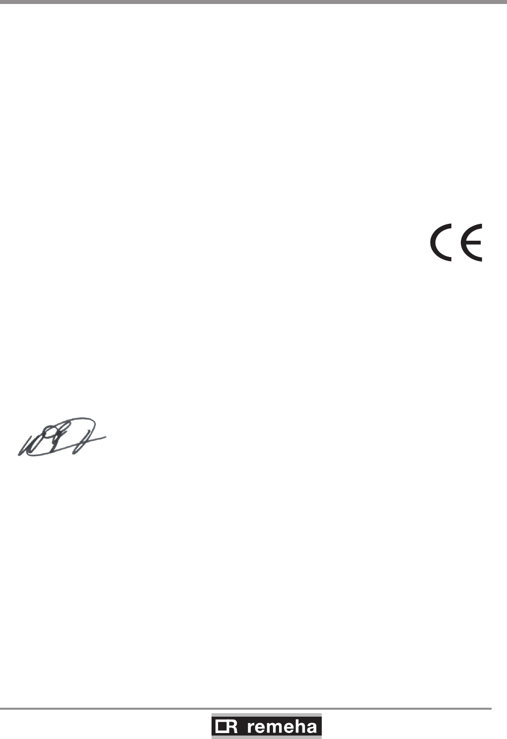
fig. 01 Elevation drawings
4.2 Dimensions
Connection Gas 210 ECO PRO 80/120/160 Gas 210 ECO PRO 200
É Flow 1¼” male thread 1½” male thread (fit supplied adapter 1¼” > 1½”)
Ê Return 1¼” male thread 1½” male thread (fit supplied adapter 1¼” > 1½”)
Gas connection 1¼” male thread 1¼” male thread
Ò Condensate drain Ø 32 mm external Ø 32 mm external
Ð Combustion air supply Ø 150 mm Ø 150 mm
Ñ Flue gas outlet Ø 150 mm Ø 150 mm
Dimension “A” 1309 mm 1324 mm
Ì Second return (option) 1¼” male thread 1¼” male thread
GAS 210 ECO PRO
12
114494-03
4. Installation
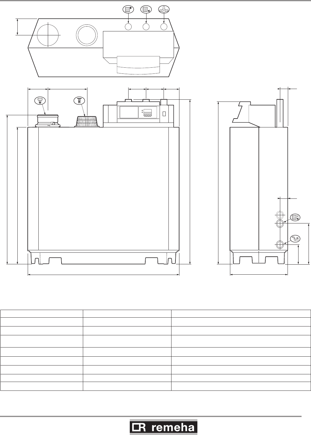
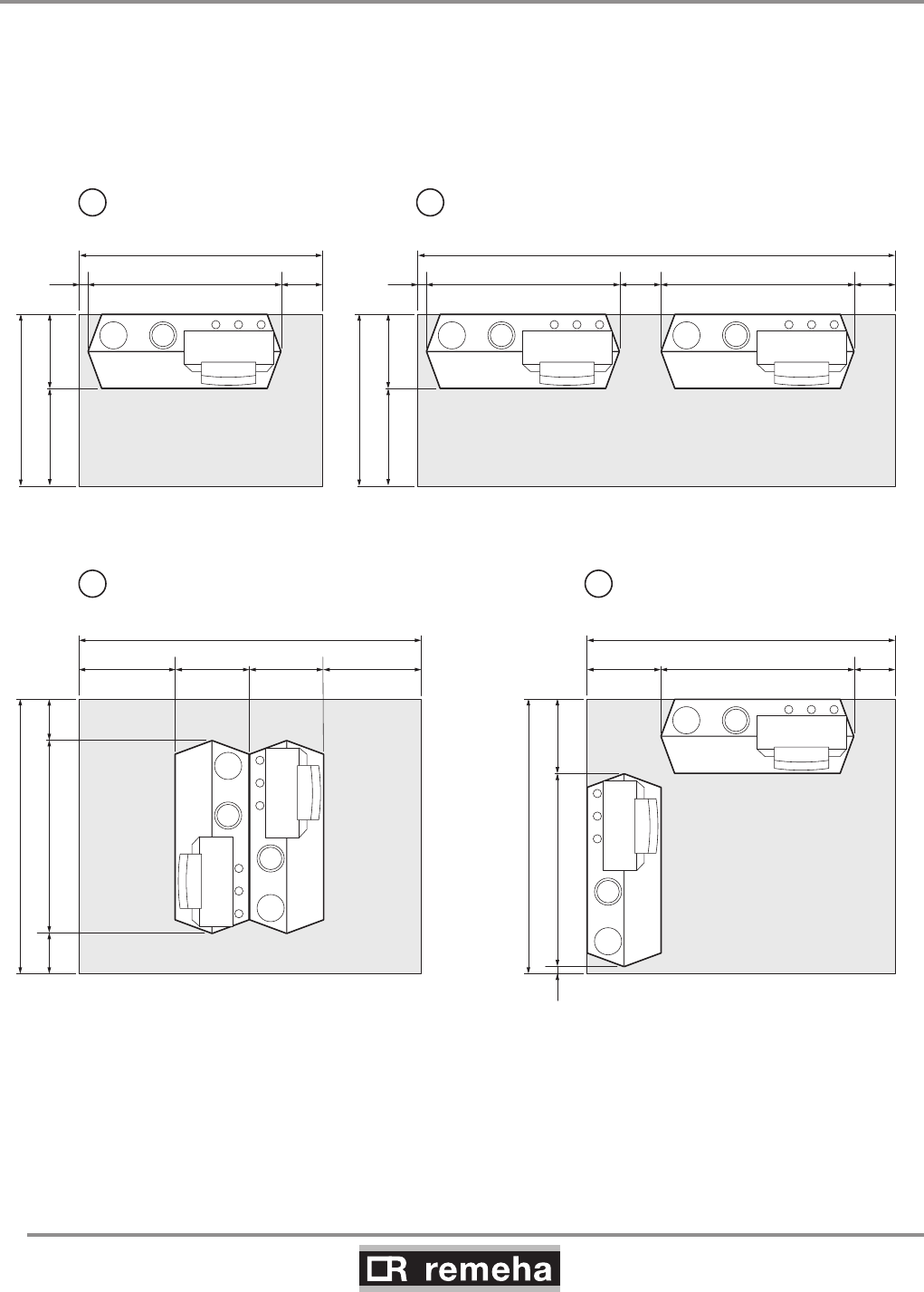
4.3 Installation and service clearances
Clearance of at least 60 cm is required at the front of the boiler.
However, we recommend a clearance of 1 m. We recommend a
clearance of at least 40 cm above the boiler control panel, at least
5 cm on the left side and at least 25 cm on the right side in con-
nection with condensed water discharge. Install a gas cock in the
immediate vicinity of/above the boiler.
1050
450600
1490
250119050
1690
4501190
1890
2501190450
50
1690
1190
2100
600450 450600
250 250
1050
450600
2930
250119050 2501190
1
114492LTAL21H002a
2
3 4
fig. 02 Boiler room installation options

114494-03
GAS 210 ECO PRO
13
5. Water-side connections
5. Water-side connections
5.1.1 Condensed water discharge
Discharge the condensed water directly into a foul water drain. In
view of the acidity level of condensate (pH between 3 and 5), only
use plastic material for the discharge pipe. After assembly, fill the
trap with clean water. Make an open connection with the drain. The
discharge pipe must slope down by at least 30 mm/m. Condensed
water must not be discharged into gutters or rain water down pipes.
5.1.2 Water treatment
• Use untreated tap water only to fill the CH system.
• The pH value of the system water must be between 7 and 9.
• Where inhibitors are being used, please refer to Broag recom-
mendations in this section and follow the manufactures instructi-
ons given.
If used correctly water treatment can improve the boilers efficiency
and increase the anticipated life expectancy of the boiler.
For further information a special document “Remeha water quality
regulations” is available from Broag. The regulations mentioned in
this document must be followed.
As most systems contain a variety of metals, it is considered good
practice to provide some form of water treatment in order to pre-
vent or reduce the following:
• Metallic corrosion
• Formation of scale and sludge
• Microbiological contamination
• Chemical changes in the untreated system water
All scale deposits, however small, will reduce the efficiency of the
boiler and should be prevented.
Suitable chemicals and their use should be discussed with a spe-
cialist water treatment company prior to carrying out any work
(environmental aspects, health aspects). The specification of the
system and manufacturers recommendations must be taken into
account, along with the age and condition of the system. New sys-
tems should be flushed thoroughly to BS 7593(1992) to remove
all traces of flux, debris, grease and metal swarf generated dur-
ing installation. Care to be taken with old systems to ensure any
black metallic iron oxide sludge and other corrosive residues are
removed, again by power flushing, ensuring that the system is
drained completely from all low points.
Please ensure that the new boiler plant is not in circuit when the
flushing takes place, especially if cleansing chemicals are used to
assist the process.
GAS 210 ECO PRO
14
114494-03
5. Water-side connections
It is important to check the inhibitor concentration after installa-
tion, system modifications, filling the system and every service in
accordance with these instructions.
For the correct dosage and the suitability of inhibitors for use with
our boilers and for further information on water treatment or sys-
tem cleaning we advise direct contact with either of the following
companies:
‘Copal®’ manufactured by:
Fernox, Cookson Electronics
Forsyth Road
Sheerwater
Woking
Surrey GU21 5RZ
Tel No: 01483 793200
Fax No: 01483 793201
Email: sales@fernox.com
Website: www.fernox.com
or:
5.1.3 Pressure relief valve
Install an pressure relief valve in the system, in accordance with
NEN 3028, between any valves and the boiler and in the flow pipe
within 0.5 m of the boiler.
5.1.4 Circulation pump
The boiler is equipped with a pump switch to connect an external
circulation pump. This pump is run once every 24 hours to prevent
sticking (24 hour pump operation). Only on/off pumps can be con-
trolled. For connections, see Section 8.3.6.
The hydraulic resistance for the various output options of the
boiler is as follows:
Boiler type
Hydraulic resistance at
a dT of 20°C
Hydraulic resistance at a dT
of 10°C
mbar kPa mbar kPa
210-80 165 16,5 545 54,5
210-120 135 13,5 446 44,6
210-160 170 17,0 562 56,2
210-200 180 18,0 595 59,5
5.1.5 Water flow
The maximum temperature difference between flow and return,
and the maximum rate of rise of the flow temperature and boiler
block temperature are limited by the boiler's modulating controls.
As a result, the boiler is virtually unaffected by low water flow.
However for a continuous supply of heat, the boiler requires a
minimum flow of 30 % of the nominal flow at the relevant design
temperatures.
Sentinal ‘X100®’ manufactured by:
Sentinel Performance Solutions
The Heath Business & Technical
Park
Runcorn
Cheshire,
WA7 4QX
Tel No: 0800 389 4670
Fax No: 0800 389 4677
Email: info.uk@sentinel-solutions.net
Website: www.sentinel-solutions.net
0 10 20 30 40
35
D
V
∆T (°C)
P (%)
114492LTAL21H031
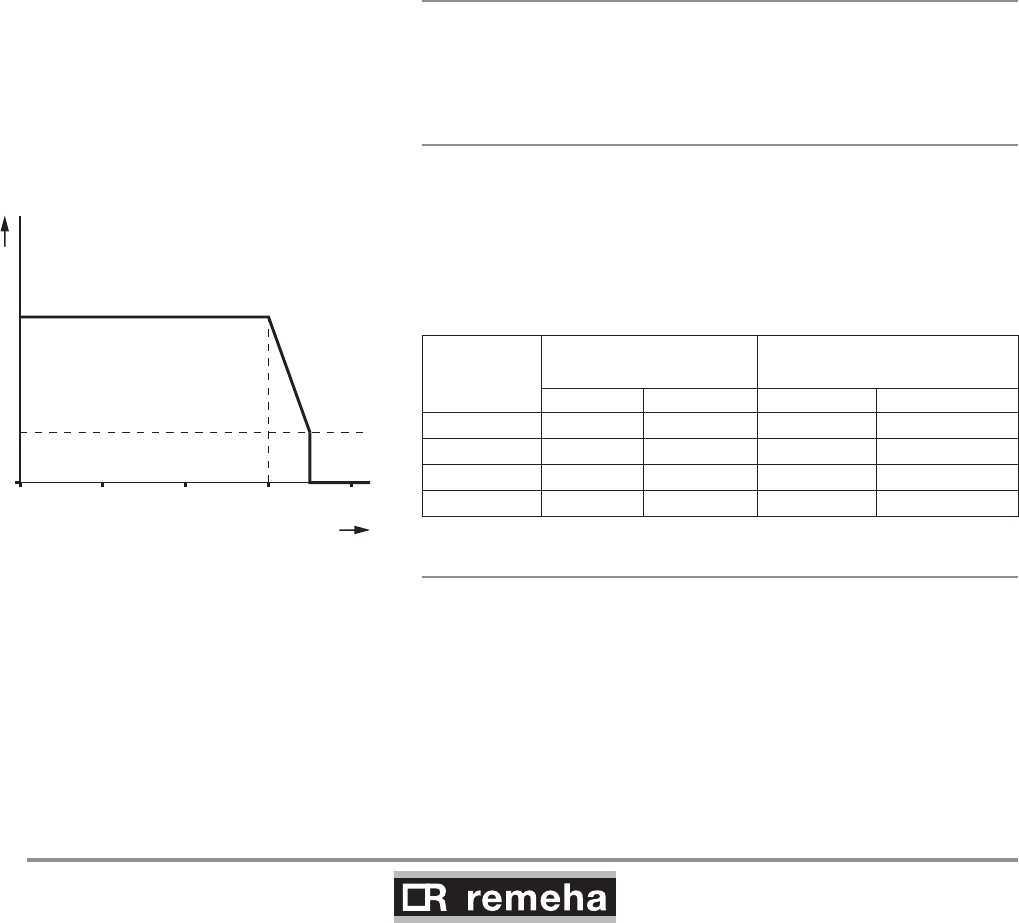
fig. 03 Output control characteristic
V = full load P = heat output
D = part load ∆T = temperature difference
fig. 03 Output control characteristic
114492LTAL21H031
V = full load P = heat output
D = part load ∆T = temperature difference
114494-03
GAS 210 ECO PRO
15
6. Gas-side connections
6.1 Gas connection
6.2 Gas pressure
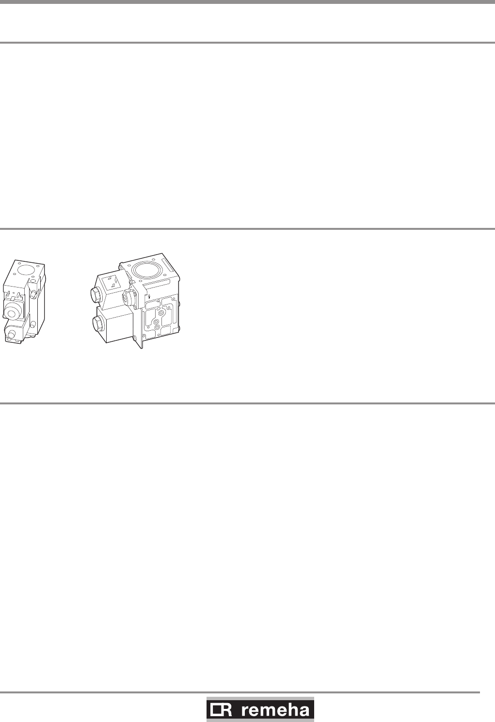
114492LTAL21H003a
5+6 L3+4 L
fig. 04 Gas multiblocks
6.3 Gas/air ratio control
The boiler is suitable for use with natural gas and propane* cat-
egory II2H3P
. For other types of natural gas, consult our Technical
department. All gas appliances must, by law, be installed by com-
petent persons (e.g. Corgi). Failure to install appliances correctly
could lead to prosecution. It is in your own interest and that of
safety to ensure that the law is complied with.
The gas connection is at the top of the boiler. We recommend
installing a gas filter in the gas supply pipe to avoid pollution of the
gas multiblock. The gas filter's resistance must not be so high that
the minimum inlet gas pressure can no longer be achieved.
* Refer to Broag for using propane.
The boiler has been factory set and tested by Remeha to natural
gas (G20) - with an inlet pressure of 17 mbar.
The boiler is suitable for 17 - 30 mbar inlet gas pressure.
For propane (LPG), an inlet pressure of 37 - 50 mbar is required.
The boiler has a zero governor gas valve. This gas valve main-
tains the ratio between the gas and air quantities in the burner at
a constant level under variable loads. This ensures clean and reli-
able combustion and high efficiency across the entire load range.
6. Gas-side connections

GAS 210 ECO PRO
16
114494-03
7. Connecting the flue gas discharge and air supply
7. Connecting the flue gas discharge and air supply
The Remeha Gas 210 PRO is suitable for conventional room ven-
tilated or room sealed operation. Specify at the time of ordering if
the boiler is to be supplied for room sealed operation. In that case,
the boiler will be supplied with a purpose-designed room sealed
terminal, air supply connection and some accessories. The air
supply connection should rest on the heat exchanger underneath
the boiler casing after removing the standard perforated air inlet
cover. Horizontal components in the flue gas discharge system
should slope towards the boiler. Horizontal components in the air
supply system should slope towards the supply opening.
Room sealed terminals should comply with the national require-
ments for both horizontal and vertical outlet constructions.
Care should be taken when siting flue exit positions as a vapour
plume will be visible when the boiler is operational (flue gas tem-
perature will be less than 80°C resulting in the water vapour con-
densing out on contact with the air).
Classification due to discharging flue gases
The boiler is approved according to CE with classification:
Type B23: Conventional room ventilated appliance without draft
diverter. Air supply from boiler room; flue gas discharge on roof.
Type B23P: Conventional room ventilated boiler without draft
diverter. Air supply from boiler room: flue gas discharge on roof,
metal flue gas discharge with CE symbol, meets pressure class P1.
Type C13: Room sealed boiler, connected to combined wall outlet.
Type C33: Room sealed appliance, connected to combined roof
outlet.
Type C43: Room sealed appliance in cascade configuration, con-
nected via two ducts to a common duct system serving more than
one appliance.
Type C53: Room sealed appliance, connected to separate ducts
for the air supply and flue gas discharge, terminated in zones of
different pressure.
Type C63: Room sealed appliance, supplied without the terminal
or the air supply and flue gas discharge ducts.
Type C83: Room sealed appliance, connected to separate air
supply and flue gas discharge duct, with flue gas discharge duct
always in underpressure.
7.1 General
7.2 Conventional open flue installation
The open flue version extracts the necessary combustion air from
the plant room or compartment. A table showing the maximum dis-
charge lengths can be found in Section 7.2.1.
114494-03
GAS 210 ECO PRO
17
7. Connecting the flue gas discharge and air supply
• The air supply opening must stay open.
• The installation area or boiler room must be equipped with the
necessary combustion air supply openings. These openings
must not be obstructed or shut off.
• The combustion air supply must be free of dust and chemically-
aggressive agents (such as trichloroethylene or halogenated
hydrocarbons), as used in aerosol cans, certain types of
adhesive, certain solvents and cleaning agents, and paint, etc.
7.2.1 Possible lengths for the flue gas discharge pipe
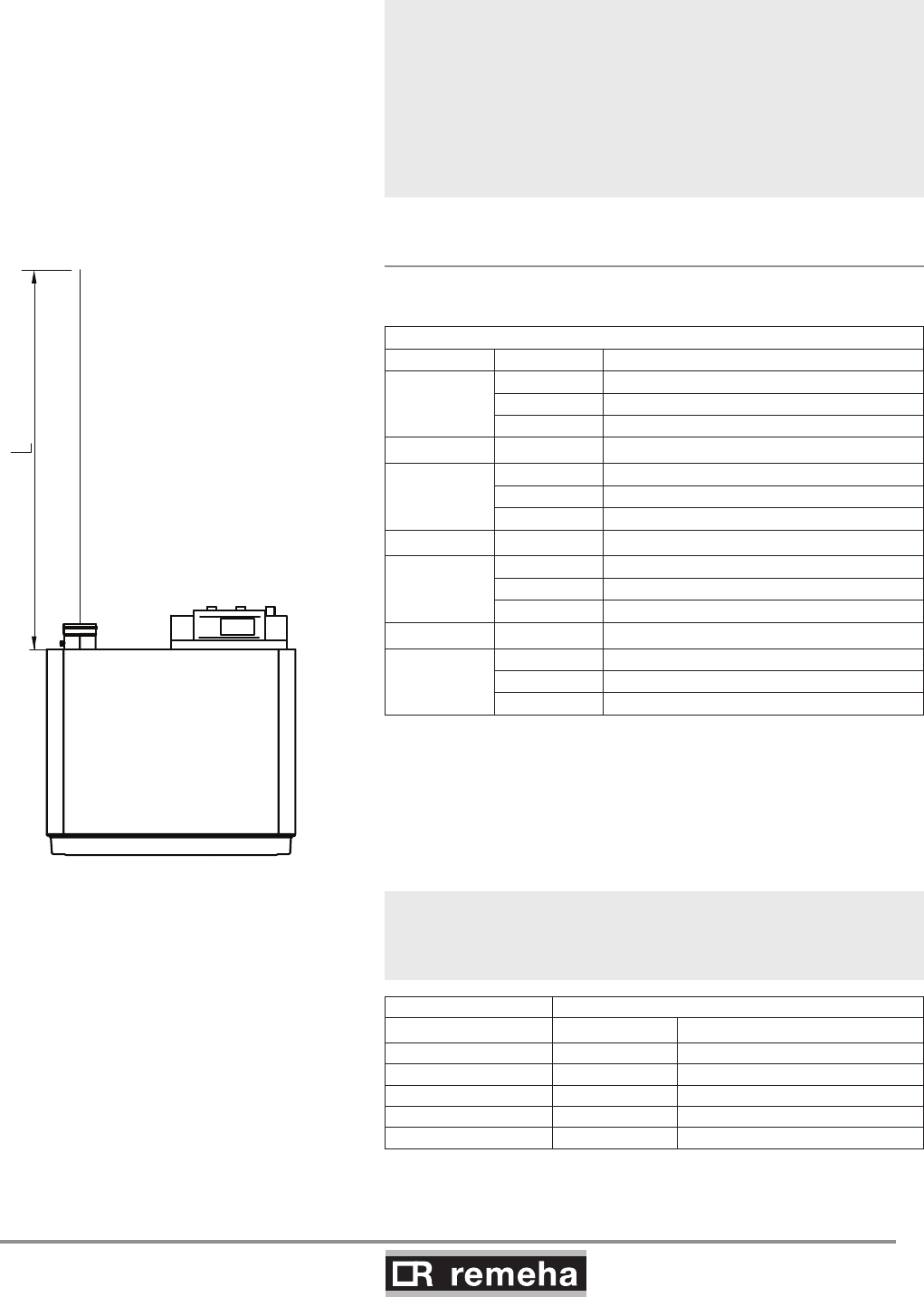
Conventional room ventilated, type B23 according to CE.
fig. 05 Piping for the conventional room ventilated
Maximum permitted flue gas discharge lengths (L) in m
Boiler type D (mm) Free discharge
210-80
100 18
110 35
130 +
210-120
110 20
130 48
150 +
210-160
130 22
150 45
180 +
210-200
130 14
150 31
180 +
table 01 Flue gas discharge table for the open version
+ = Lengths up to 50m possible. For longer lengths, consult our
Technical department
When flue gas discharge pipes with diameters other than 150 mm
are used, an adapter is required: Ø150/100mm, Ø150/110mm,
Ø150/130mm or Ø150/180mm.
For each additional 90° or 45° bend, the pipe length must be
reduced by the amount shown in table 02.
D in mm length in m
90° bend 45° bend
Ø 100 R=½D 4.9 1.4
Ø 110 R=½D 5.4 5.1
Ø 130 R=D 1.8 1.0
Ø 150 R=D 2.1 1.2
Ø 180 R=D 2.5 1.4
table 02 Metres to be deducted per bend
GAS 210 ECO PRO
18
114494-03
The room sealed installation is based on the use of an air supply
pipe connected directly to the boiler. This increases the number of
installation options within a building, while the discharge location is
subject to less stringent requirements because the air supply and
flue gas discharge can be incorporated in the same pressure field.
Additional ventilation will be required to the room/compartment in
accordance with BS 6644-2005 (compartment ventilation).
In addition, air from outside is usually cleaner, which has a ben-
eficial effect on the boiler service life. An air supply and flue gas
discharge table for the enclosed version of the boiler can be found
in table 03. For discharge in two different pressure fields, see Sec-
tion 7.3.2.
The boilers can be installed on a flue dilution system, but must
have a total flue break to avoid boiler controls being affected
by the flue dilution fan pressures. For full details please contact
Broag.
7.3.1 Possible lengths for the air supply and flue
gas discharge
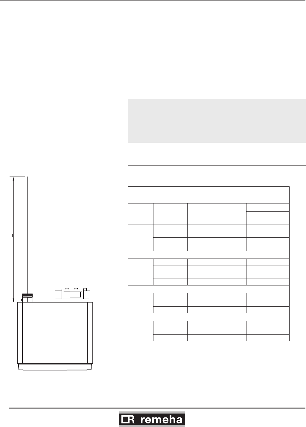
Room sealed appliance, type C33 according to CE.
Maximum acceptable flue gas discharge/air supply pipe
lengths (L) in m
Boiler
Model
Pipe Ø D
(mm)
Calculated with
concentric roof feed-
through Dnominal (mm) [m]
210-80
100 100 8
130 130 +
130 150 +
150 150 +
210-120
100 100 3
130 130 22
130 150 25
150 150 +
210-160
130 150 11
150 150 22
180 150 +
210-200
130 130 4
150 150 13
180 150 +
table 03 Air supply and flue gas discharge table for the
enclosed version
+ = Lengths up to 30m possible. For longer lengths, consult
our Technical department
fig. 06 Piping for the room sealed appliance
0021H7900017
7. Connecting the flue gas discharge and air supply
7.3 Room sealed installation
114494-03
GAS 210 ECO PRO
19
7. Connecting the flue gas discharge and air supply
When air supply and flue gas discharge pipes with diameters other
than 150 mm are used, adapters are required: Ø150/100mm,
Ø150/110mm, Ø150/130mm or Ø150/180mm and, for connec-
tion to our standard combined vertical roof feed-through sets, also
Ø180/150mm, Ø130/150mm or Ø110/150mm.
For each additional 90° or 45° bend, the pipe length must be
reduced by the amount shown in table 04.
fig. 07 Vertical roof feed-through for room sealed operation
Pdf dakdoorvoer
D in mm length in m
90° bend 45° bend
Ø 100 R=½D 4.9 1.4
Ø 110 R=½D 5.4 5.1
Ø 130 R=D 1.8 1.0
Ø 150 R=D 2.1 1.2
Ø 180 R=D 2.5 1.4
table 04 Metres to be deducted per bend
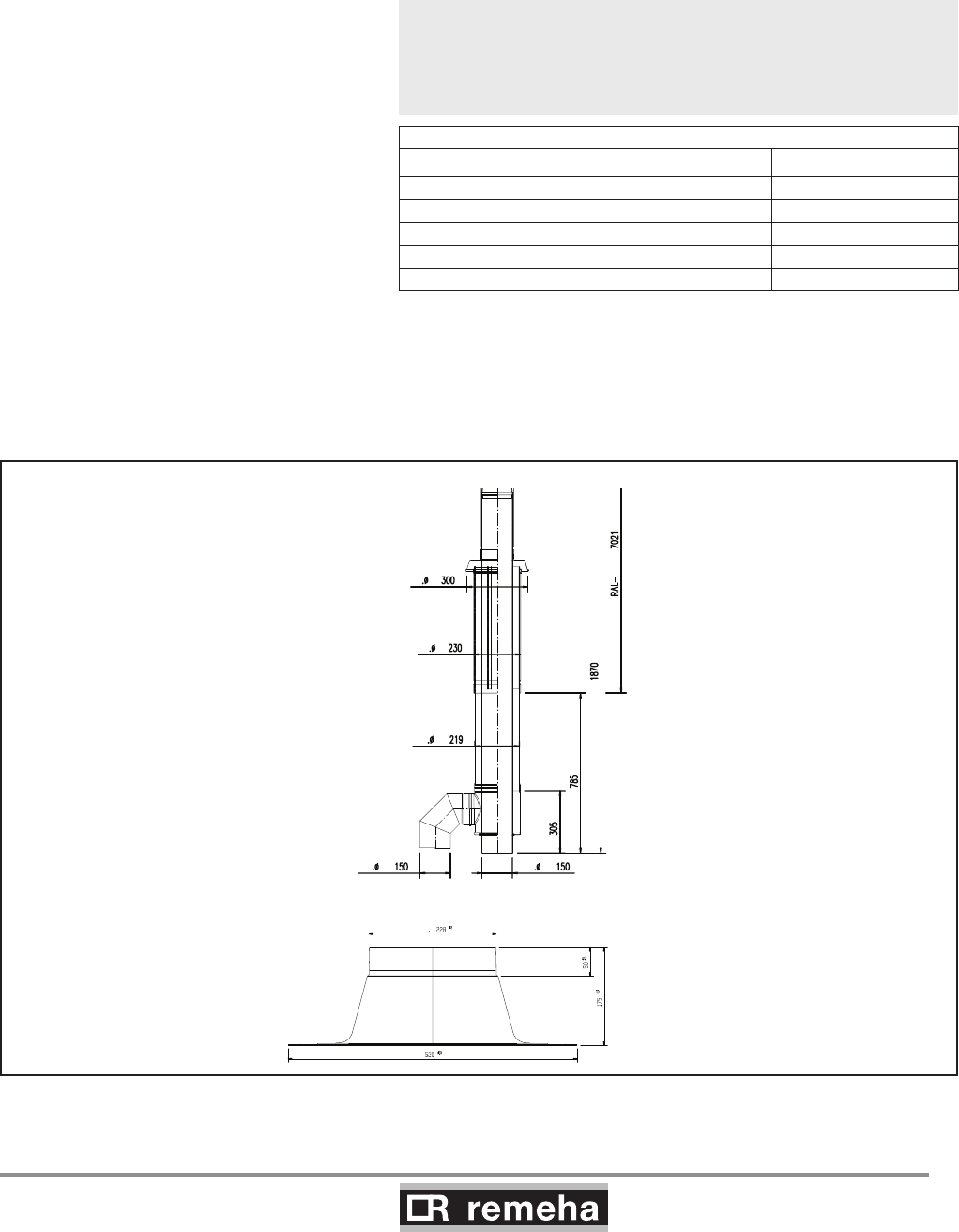
For enclosed versions, combined vertical roof feed-through sets
are available, as well as sealing plates for flat roofs, in accordance
with the following drawings. Please consult our Technical depart-
ment for this option.
Afgeleide van tek. Nr.
00.21H.79.00006.B & 00.20H.79.00024
Ext
Ext Ext
Ext
Int
Int
Epo y l y rx a e
GAS 210 ECO PRO
20
114494-03
7. Connecting the flue gas discharge and air supply
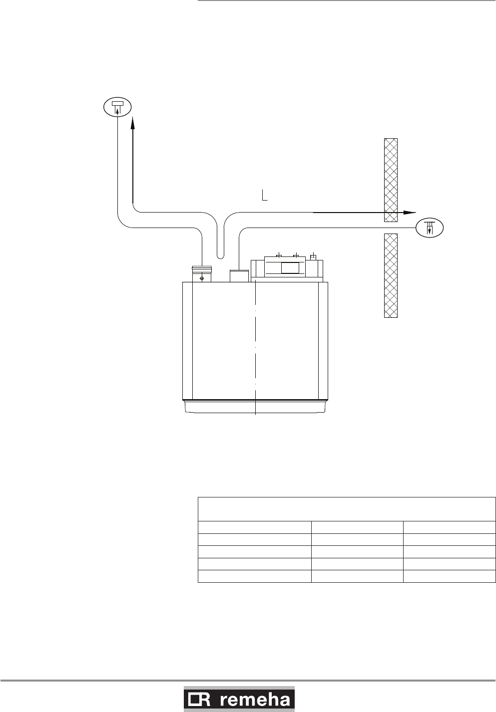
7.3.2 Discharge in different pressure areas
For installations where supply and discharge points are in two dif-
ferent pressure zones CLV system please contact Broag Techni-
cal Dept. for further details and advice. The maximum acceptable
height difference between combustion air supply and flue gas
discharge is 36 m and the maximum acceptable length of the air
supply and flue gas discharge combined is shown in table 05.
fig. 08 Discharge in different pressure areas
Maximum permitted flue gas discharge and
air supply pipe lengths
Boiler model D in mm L in m
210-80 150 36
210-120 150 36
210-160 150 23
210-200 150 11
table 05 Air supply and flue gas discharge table for 'simplified
CLV system'

114494-03
GAS 210 ECO PRO
21
7. Connecting the flue gas discharge and air supply
7.3.3 Connection of flue gas discharge and choice
of material
Connecting the flue gas discharge:
Remove the cap from the flue gas discharge opening Ñ;
• Fit the flue gas discharge pipes seamlessly together.
• Seams and joints must be airtight and watertight or fit seamlessly.
• Horizontal parts must be oriented towards the boiler at a gradient (min.
5 cm per metre).
• Connect the pipes stress-free.
• Flue gas discharge pipes longer than 2 m must be fixed separately and
must not rest on the boiler.
Flue gas discharge:
Material:
Rigid single walled: stainless steel (316), aluminium or plastic (to comply
with building regulations).
Flexible: stainless steel (316).
Construction: all joints and seams should be gastight and watertight with
the horizontal runs graded towards the boiler (min. discharge 5 cm per
meter) to allow condensate free drainage to the boiler. Flue gas discharg-
es longer than 2 meters must be supported independently and may not
rest on the boiler.
The flue outlet should terminate with reduction cone and bird guard only
(chinamans hat or GLC type terminals etc. should not be used).
7.3.4 Air supply connection and choice of material
Connecting air supply:
Remove air supply grille from the air supply opening Ð;
• Fit the air supply pipes seamlessly together.
• Seams and joints must be airtight and watertight or fit seamlessly.
• Horizontal parts must be oriented towards the discharge at a
gradient (min. 5 cm per metre).
• Connect the pipes stress-free.
Air supply:
Material:
Single walled, rigid or flexible: aluminium, stainless steel and plastic (to
comply with building regulations).
Air supply ducts longer than 2 meters must be supported independently
and may not rest on the boiler air inlet. Care must be taken to ensure that
if water is able to enter the duct it will run away from the boiler air inlet
connection or supply a suitable train c/w water seal trap.
7.3.5 Additional Directives
Please refer to the manufacturer’s instructions for the material in ques-
tion when installing the flue gas discharge and air supply materials. If the
flue gas discharge and air supply materials are not installed according to
the instructions (e.g. they are not leakproof, not clamped in place etc.),
this may cause hazardous situations and/or result in bodily injury. After
assembly, check at least all flue gas and air–carrying parts for tightness.

GAS 210 ECO PRO
22
114494-03
8. Control and electrical connections
8. Control and electrical connections
8.1 General
The boiler is equipped with electronic control and safety equip-
ment with ionisation flame protection. The advanced boiler control
(abc®), is a microprocessor that protects and controls the boiler.
The boiler is fully prewired; all external connections are made
on the terminal strips. Connect the boiler to the mains supply in
accordance with the local electricity supplier's instructions and IEE
regulations.
8.1.1 Boiler control
The heat output of the Remeha Gas 210 ECO PRO can be con-
trolled as follows:
- Modulating, where the output modulates between the minimum
and maximum values on the basis of the flow temperature
defined by the modulating controller.
- On/off control, where the heat output modulates between
the minimum and maximum values on the basis of the flow
temperature set in the unit. This can be combined with an
outside sensor so that the internal heating curve is used.
- Analogue control (0-10 V), where the heat output or
temperature is controlled by a 0-10 V signal, see Section 8.4.4.
Only possible with optional 0 - 10 V control PCB (IF-01).
8.1.2 Modulating controls general
The modulating nature of the boiler is used to maximum effect with
a modulating controller based on room and/or outside tempera-
tures. If the controller demands heat, the boiler supplies the heat
output. If the controller demands a flow temperature, the boiler
modulates to this value. This increases the number of operating
hours and drastically reduces the number of starts. Combined with
the fixed gas/air mixture, this results in greater efficiency.
Various types of modulating controls can be connected, including
the following:
- Modulating room control, see Section 8.1.3;
- Modulating weather-compensated control see Section 8.1.4;
- Modulating cascade control, see Section 8.1.5.
8.1.3 Modulating room control
The boiler is set up for communication via the OpenTherm pro-
tocol. Modulating controllers can be connected according to the
OpenTherm protocol, e.g. the Remeha iSense. The controller is
mounted in a reference area. Connection is made with a two-core
cable to the On/off - OT terminals of terminal strip X6 (not polarity
sensitive).
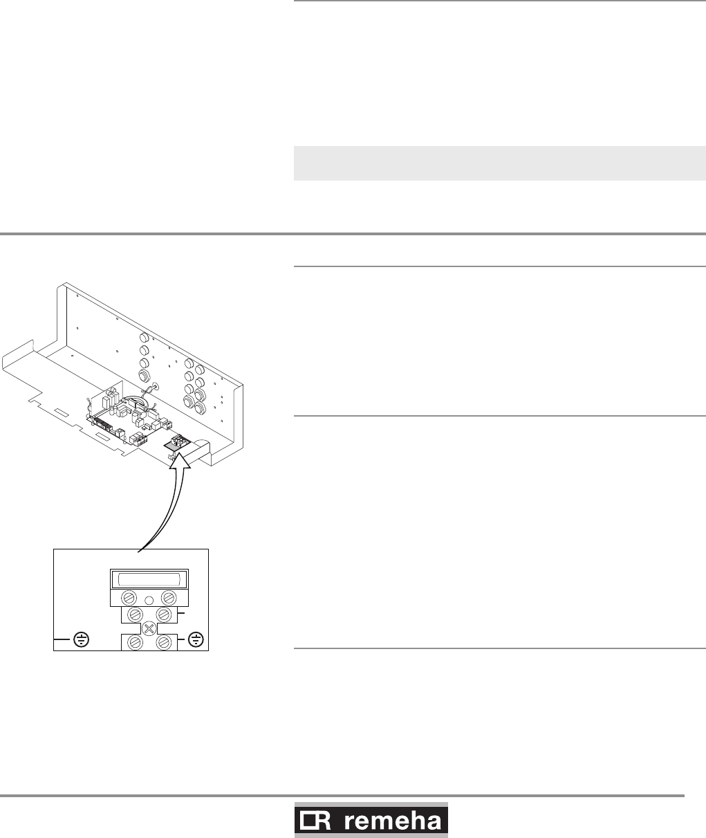
8.1.4 Modulating weather-compensated control
rematic®
The following optional controller can be supplied by Broag-Reme-
ha. The controller is supplied with a connection adapter and inter-
face that are built into the boiler. The connections for this feature
are fully pre-wired.
114494-03
GAS 210 ECO PRO
23
8. Control and electrical connections
fig. 09 Connect mains lead
N
L
230Vac, 50Hz, F6.3AT
114492LTAL21H004a
rematic® 2945 C3 K
In addition to the weather-compensated boiler pre-control, this
controller provides optimum start, dual zone weather compensa-
tion and priority DHW (if required). Fit the controller in the boiler.
Connection takes place using the supplied rematic® adapter and
the supplied interface that can be integrated in the control panel.
Refer to the relevant controller documentation for detailed informa-
tion.
8.1.5 Modulating cascade controller MC4
The Remeha Celcia MC4 cascade controller is suitable for the
modulated control of 2 to 4 Remeha Gas 210 PRO boilers in cas-
cade. This controller is wall-mounted and communicates according
the OpenTherm protocol. We recommend using our Celcia MC4
modulating cascade controller in conjunction with the iSenseTime/
Weather compensation controller. Refer to the relevant controller
documentation for detailed information.
iSense with MC4 will only control up to 4 boilers
in cascade
8.2 Electrical specifications
8.2.1 Mains voltage
The boiler is suitable for a 230 V-50 Hz supply with live/neutral/
earth (the control is phase/neutral sensitive). Other connection
values are only acceptable if an isolating transformer is installed.
Connect the mains lead (not supplied) to the 230 V terminal strip.
8.2.2 Control box
Mains voltage : 230 V/50 Hz
Power consumption at: stand-by/low load/full load:
- 210-80 : 4 / 36 / 125 W
- 210-120 : 4 / 37 / 193 W
- 210-160 : 4 / 53 / 206 W
- 210-200 : 4 / 54 / 317 W
Safety time: 3.5 s
Anti-hunting time: Adaptive 1 - 10 minutes.
Pump post-circulation time: adjustable between 0 and 98 minutes
or continuous (= 99 minutes), set by default to 3 minutes
Max. power consumption of external pump: 300 VA.
8.2.3 Fuse ratings
The 230 V terminal strip contains the fuse F - 6.3 AT.
This is a general fuse for all connected components.
The control unit contains the fuse F1 - 1.6 AT.
This is a fuse for the mains voltage of the control unit, gas multi-
block and ignition, excluding pump.
GAS 210 ECO PRO
24
114494-03
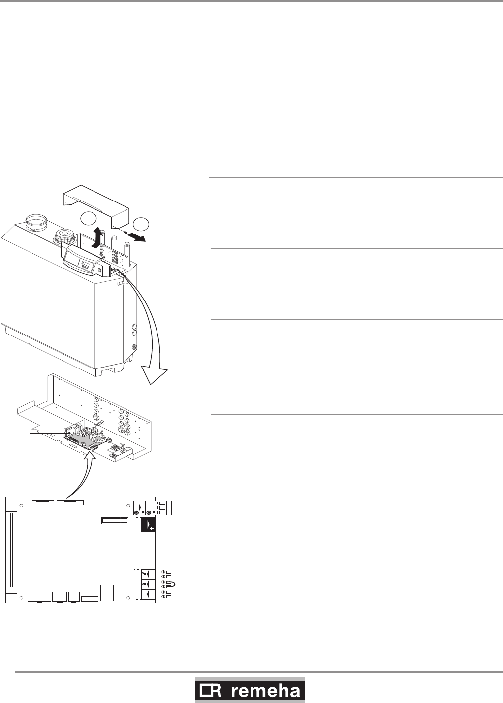
The boiler has several control, protection and regulation connec-
tion options. The standard control PCB (PCU-01) can for example
be expanded with:
• an optional 0 - 10 V control PCB (available as an accessory IF-01);
• and/or the optional expanded control/protection PCB (available as
an accessory SCU-SO1).
To install or access these PCBs, the plastic cap must be removed
from the control panel. The required external connections are
made on these (optional) PCBs. The various connection options
are detailed in the following sections.
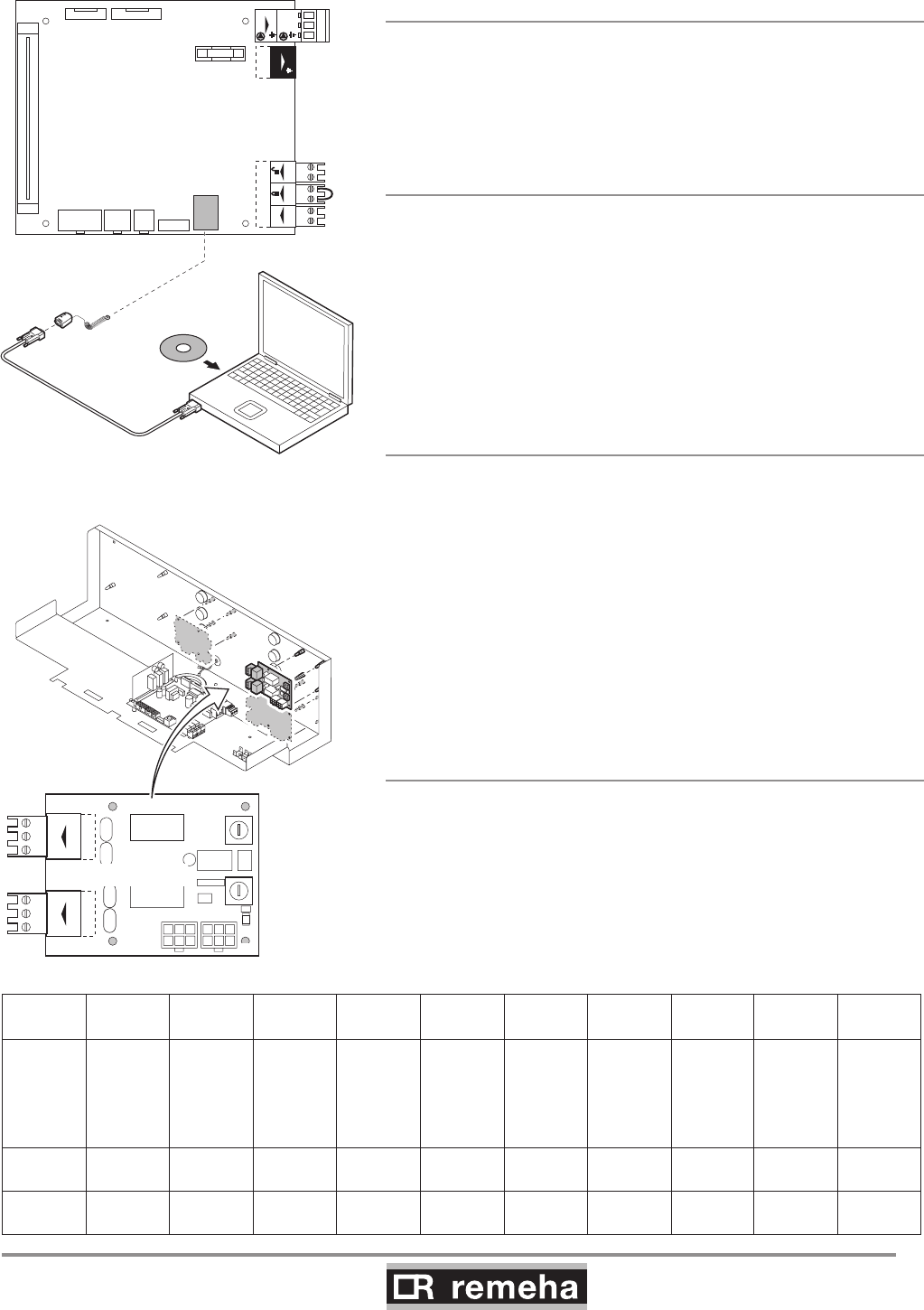
8.3.1 Connection options of standard control unit
(PCU-01)
Connected on the standard control unit (PCU-01) is the safety unit
(SU) connected, which protects the boiler.
Mainson/of
N
N L
Pump
L
OT BL RL
OT BL RL
X6
X1
X11 X10 X9 X7
X8
X2 X3
X5
X4
F1 1.6 AT
PCU-01
SU
N L
Pump
X9X11 X10
14x
2
114492LTAL21H005e
fig. 10 Standard control PCB (PCU-01) with
safety unit (SU)
8.3.2 On/off control (OT)
The boiler is suitable for connection to a ‘volt free’ on/off controller.
Connect the controller to the On/off - OT terminals of terminal
strip X6 (not polarity sensitive).
8.3.3 Modulating controls (OT)
The boiler is set up for communication via the OpenTherm proto-
col. Modulating controllers can be connected.
Connection is made with a two-core cable to the On/off - OT ter-
minals of terminal strip X6 (it does not matter which wire is con-
nected to which cable clamp).
8.3.4 External interlock (BL)
The boiler has an external interlock switch, so that the boiler can
be shutdown in the event that this switch is not made. This input
can be used in combination with a flue gas thermostat (available
as an accessory). This input relates to the BL terminals of terminal
strip X6. Remove the wire bridge before using the input.
The input's behaviour depends on the parameter 33 setting:
1 = Normal shutdown;
2 = Shutdown without frost-protection (= default);
3 = Lock out.
8. Control and electrical connections
8.3 Electrical connection options
114494-03
GAS 210 ECO PRO
25
8.3.5 Input release (RL)
The boiler is also equipped with an input release so that the burn-
er can be released/shutdown. This input can be used in combina-
tion with the limit switches on flue gas throttle valves, hydraulic
control valves, safety interlocks, etc. This input relates to the RL
terminals of terminal strip X6.
8.3.6 Circulation pump (Pump)
A pump with the following specifications can be connected:
- On/off pump with a mains voltage of 230 VAC (50 Hz) and 300
VA (maximum).
Connect the pump to the Pump terminals of terminal strip X4. The
post-circulation time of the circulation pump at the end of a heat
demand can be set according to requirements by means of a pro-
gram option at user level, see Section 9.1.6.
8.3.7 Connecting a PC
Using the optional Recom interface package a PC can be connec-
ted to the X7 “telephone connector”.
Using the Recom software you can load, change and download
various boiler settings and readings.
See the user instructions supplied with the software.
8.3.8 Connection options for the PCB - SCU - X01
The PCB - SCU - X01 is equipped with two potential-free outputs
that have a capacity of max. 230 VAC/5 A reactive/2 A inductive
(cos 0.6). It also has two rotary switches with ten positions.
See the table below for the rotary switch settings.
8. Control and electrical connections
Mainson/of
N
N L
Pump
L
OT BL RL
OT BL RL
X6
X1
X11 X10 X9 X7
X8
X2 X3
X5
X4
F1 1.6 AT
PCU-01
N L
Pump
X9X11 X10
T000058
www.remeha.com
Recom
T002747-A
sutatS
cN oNC
cN oNC
sutatS
cN oNC
cN oNC
X2a
X4
X3
0
9
8
7
6
5
4
3
2
1
00
9
8
7
6
5
4
3
2
1
0
SCU-X01
X2
Nr0123456789
Descrip-
tion
Alarm
Alarm
inverted
= fail
safe
Burning Burning
inverted
Burning
low
Burning
high
Service
report
CH-
mode
DWH-
mode
CH-
pump
Standby C-NO C-NC C-NO C-NC C-NO C-NO NA NA NA C-NO
Active C-NC C-NO C-NC C-NO C-NC C-NC NA NA NA C-NC
fig. 11 Connecting a PC
GAS 210 ECO PRO
26
114494-03
8. Control and electrical connections
Status 0-10 0-10
Nc NoC
Nc No OTm 0 + 0 +C
OTm 0 + 0 +
X5
X4
X1
IF-01
%
1
2
114492LTAL21H006a
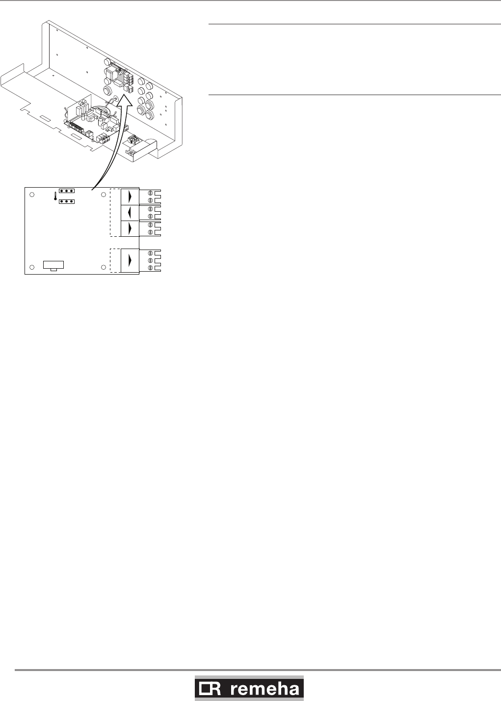
8.4 Connection options for 0 - 10 V control PCB (IF-01)
fig. 12 Jumper 2
8.4.1 Connection status (Nc)
If the boiler locks out, a relay is de-energised and the alarm can
be transmitted via a potential-free contact
(maximum 230 V, 1 A) on terminals Nc and C of terminal strip X4.
8.4.2 OTm connection
The interface uses OpenTherm to communicate with the boiler
control. The OTm connection on terminal strip X5 must therefore
be connected to the OpenTherm OT input of the boiler control.
114494-03
GAS 210 ECO PRO
27
8. Control and electrical connections
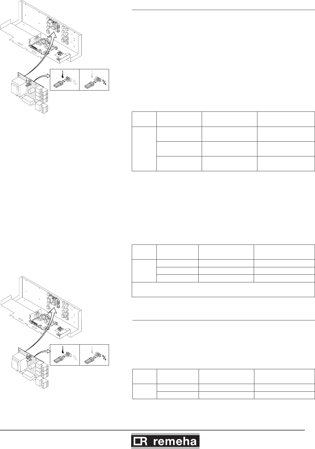
8.4.3 Analogue input (0 - 10 V)
This control can be based on temperature or heat output (option-
al). The two controls are described briefly below. Connect the 0
- 10 V signal to the interface input for analogue control.
Analogue temperature-based control ()
The 0-10 V signal controls the boiler flow temperature between
0°C and 100°C. This control modulates on the basis of flow tem-
perature, where the heat output varies between the minimum and
maximum values on the basis of the set point flow temperature
calculated by the controller.
Jumper (2) on the interface is used to select either temperature ()
or boiler output (%) control.
1
2
%
1 1
114492LTAL21H024a
fig. 14 Jumper 1
1
2
114492LTAL21H023a
%
22
fig. 13 Jumper 2
Jumper
2
Input signal
[V]
Temperature
[°C]
Description
0 - 1,5 0 - 15 Boiler off
1,5 - 1,8 15 - 18 Hysteresis
1,8 - 10 18 -100 Desired temperature
table 06 Analog input signal for temperature
Analogue output-based control (%)
The 0-10 V signal controls the boiler output between 0% and
100%, where the minimum and maximum values are limited. The
minimum output is linked to the boiler's modulation depth. This
control is output modulated, where the output varies between the
minimum and maximum values on the basis of the value defined
by the controller.
Jumper
2
Ingput signal
[V]
Boiler output
[%] Description
%
0 - 2,0* 0 - 20 Boiler off
2,0 - 2,2* 20 - 22 Hysteresis
2,0* - 10 20 -100 Desired boiler output
* Dependent on the minimum modulation dept (fan rotation speeds set-
tings, pre set 20%)
table 07 Analogue input signal for boiler output
8.4.4 Analogue output (0 - 10 V)
If this feedback message is received, temperature or heat output
can be selected. The two are described briefly below.
Jumper (1) on the interface is used to select either temperature ()
or boiler output (%).
Jumper
1
Output signal
[V]
Temperature
[°C] Description
0,5 - Alarm
1- 10 10 - 100 Delivered temperature
table 08 Analogue output signal for temperature
GAS 210 ECO PRO
28
114494-03
8. Control and electrical connections
Jumper
1
Output signal
[V]
Boiler output
[%] Description
%
00 - 15 Boiler off
0,5 15 - 18 Alarm
2,0* - 10 20 - 100 Delivered boiler output
* Dependent on the minimum modulation dept (fan rotation speeds set-
tings, pre set 20%)
table 09 Analogue output signal for boiler output
VPS
VPS
X1
X3
X4
X5
X2
SCU-S01
GPS
GPS
Tout
Tout
Status
NcC
Nc No
No
C
Wps
O +S
O +S
N L
EgV
N L
EgV
N L
HdV
N L
HdV
N L
FgV
N L
FgV
114492LTAL21H007c
F1 4 AT
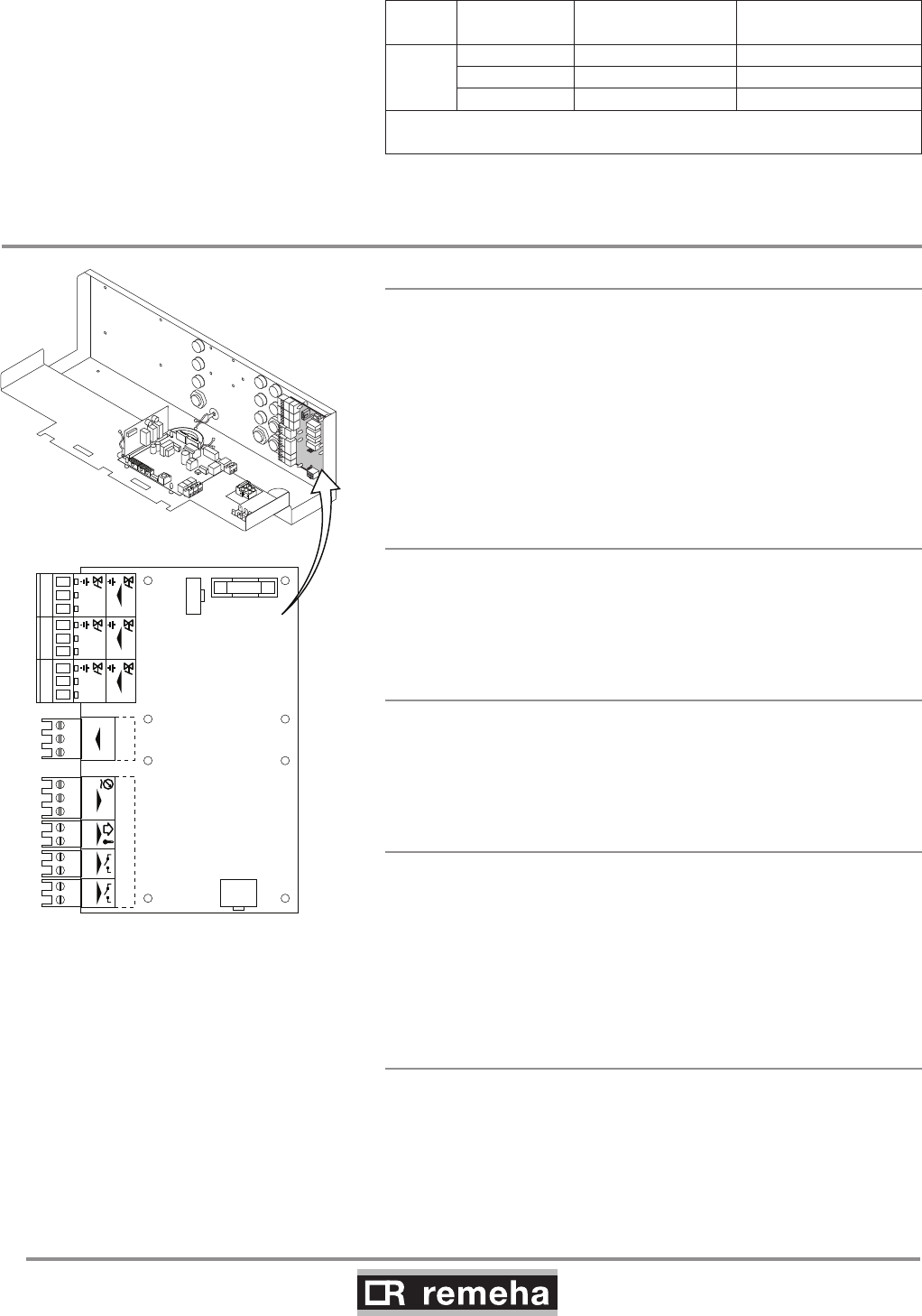
fig. 15 Expanded control/protection PCB (SCU-SO1).
8.5 Connection options of the optional expanded control/protection PCB
(SCU-SO1)
8.5.1 Flue gas damper control (FgV)
In a cascade configuration, a flue gas damper (available as an
accessory) prevents flue gases from being discharged through a
non-operating boiler, with flue gas cascade. Therefore, the boiler
is suitable for flue gas overpressure systems. Consult our Techni-
cal department. Connect the flue gas damper to the FgV terminals
of terminal strip X3. Also fit this flue gas damper if flue gases flow
back when the boiler is in stand-by mode.
The running time of the flue gas damper must be programmed
with parameter 29.
8.5.2 Hydraulic valve control (HdV)
In a cascade configuration, a hydraulic valve prevents heat loss
when the boiler is not running. Connect the hydraulic valve to the
HdV terminals of terminal strip X3. The running time of the hydrau-
lic valve must be programmed with parameter 28.
8.5.3 External gas valve control (EgV)
If there is a heat demand, an alternating voltage of 230 V 1 A
(maximum) becomes available on the EgV terminals of terminal
strip X3 to control an external gas valve. The voltage is switched
off when the gas multiblock on the boiler closes.
8.5.4 Operation signal and failure signal (Nc / No)
The alarm or operation signal is selected using the relevant
parameter 25, see Section 9.1.6. If the boiler is operational,
the alarm or operation signal can be switched via a potential-free
contact (maximum of 230 V, 1 A) on the No and C terminals of ter-
minal strip X4. If the boiler locks out, the alarm can be transmitted
via a potential-free contact (maximum 230 V, 1 A) on terminals No
and C of terminal strip X4.
8.5.5 Water pressure sensor (Wps)
The water pressure sensor (available as an accessory) shuts
the boiler down when the minimum water pressure (0.8 bar) is
reached. To activate the water pressure sensor, a minimum pres-
sure must be set with parameter 26 (factory setting 0 = off, see
Section 9.1.6.) The pump does not run during this shutdown.
114494-03
GAS 210 ECO PRO
29
8. Control and electrical connections
Connect the water pressure sensor to the Wps terminals of termi-
nal strip X5.
0 = Earth or neutral of the power supply
S = Signal or output from the sensor
+ = Supply voltage
8.5.6 Outside temperature sensor (Tout)
To take advantage of the boiler's modulating operation during the
entire heating season, a Remeha outside temperature sensor
(available as an accessory) can be used in combination with an
on/off control or connection. Connect the on/off control or connec-
tion to the On/off terminals of terminal strip X6 on the standard
control PCB (PCU-01) and the outside temperature sensor to the
Tout terminals of terminal strip X5 on the optional expanded con-
trol/protection PCB (SCU-SO1). The unit modulates with a heat
demand from the controller or because of a connection to a flow
temperature corresponding to the outside temperature (see heat-
ing curve graph).
Fitting the outside temperature sensor
Fit the external sensor, protected against direct sunlight, to the
north or north-west of the building, at a height of at least 2.5
metres from ground level. Do not fit the outside temperature sen-
sor near windows, doors, ventilation grills and extractors, etc.
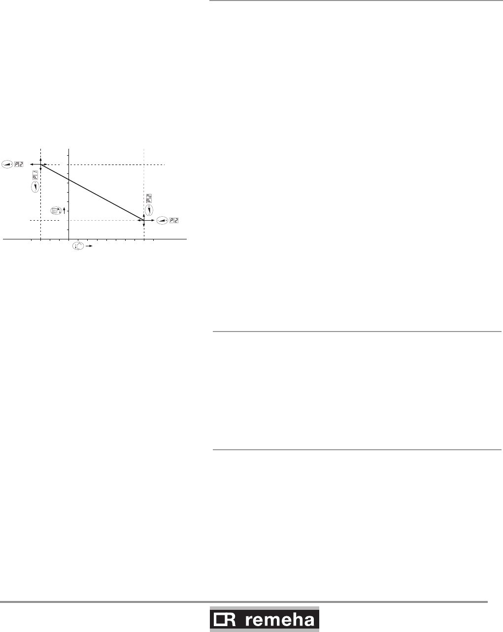
Heating curve setting
The maximum flow temperature setting is also the setting for the
‘top’ of the heating curve, i.e. the required flow temperature for an
outside temperature of -15°C. The baseline of the heating curve is
also adjustable and can be changed at service level, see Section
9.1.6. A linear relationship exists between the outside tempera-
tures mentioned and the corresponding flow temperatures.
20
40
60
80
0 10 20-15
F
114492LTAL21H025b
1
3
2
fig. 16 Heating curve graph
F = factory setting
8.5.7 Minimum gas pressure switch (Gps)
The minimum gas pressure (available as an accessory) switch
shuts the boiler down if the inlet gas pressure becomes too low.
Connect the minimum gas pressure switch to the Gps terminals
of terminal strip X5. The presence of the gas pressure switch
must be activated using parameter 27 in the setting mode (see
Section 9.1.6).
8.5.8 Gas leakage control (VPS; only for 210- 160
and 210- 200 boilers)
The gas leakage control checks and controls the safety valves on
the gas block via a VPS system. The test takes place when the
boiler starts. In the event of a leak in the gas block, the boiler will
lock out. Connect the gas leakage control to the VPS terminals of
terminal strip X5. The presence of a gas leakage control must be
entered using parameter 31, see Section 9.1.6.
GAS 210 ECO PRO
30
114494-03
9. Commissioning
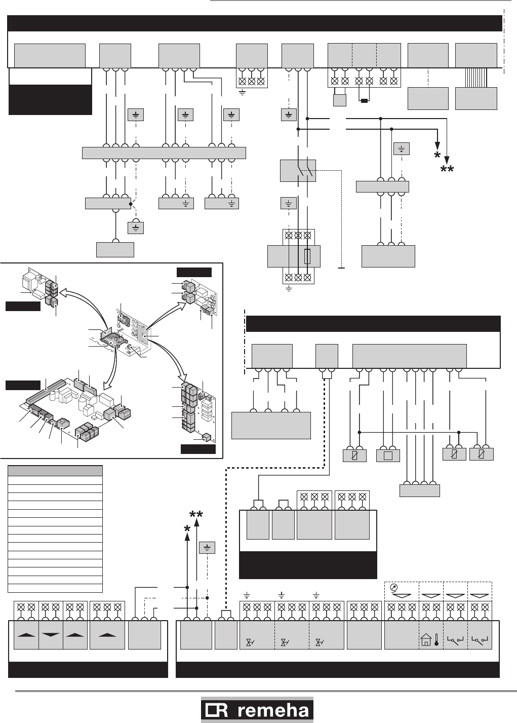
8.5.9 Wiring diagram
T002609-04-C
IF-01
123
X01
BK
BL
GN/YW
X01
132
X05
+-
0-10V
+-
0-10V
OTm Nc C
Status
No
X04
SECONDARY CONTROL UNIT - SCU-S01 (OPTION)
X02
1.....6
X10
1.....6
X09
1234
1X91425
Fan
WH
BR
GN
YW
Fgv
21
Hdv
45
Egv
78369
NNNLLL
X03
Status
CNoNc
213
X04
OS+
214567
38
9
X05
WpsToutGps VPs
X11
12 35 4671089
Flow
temp.
Return
temp.
Heat exch.
temp.
P
Flue gas
pressure
switch
PSU
(Parameter
storage unit)
WH
BK
RD BLOR
OR GL/
WH
BR/
WH
BK/
WH
BL/
WH
PE-2
GN/YW
PRIMARY CONTROL UNIT - PCU-01
X50
6.3AT
LN
X01
SAFETY UNIT
- SU-01
PRIMARY CONTROL UNIT - PCU-01
X02
123
X03
1234
X04
12
Pump
3
LN
X51
X05
123
BL
BK
BL
BR
Mains
X07
PC
X08
11
0
DISPLAY
OT
1
On / Off
BL
34
RL
562
T
X06
PE-2
GN/
YW
PE-1
GN/YW
14X235 13 12
PE-7
GN/YW
1X5532
Fan
BR
BL
GN/YW
Boiler
switch
on / off
Power supply
230V,50Hz
BL
BK
213X21
Ignition
transformer
Elektrode
BL
Safety shut-off
valve1
21
Safety shut-off
valve 2
21
BR BR
PE-6 PE-4 PE-5
PE-12
11X235 9810 21 3675
PE-11
GY
BL
BK
GN/YW
BL
BR
GN/YW BL
BR
GN/YW
GN/YWGN/YWGN/YW
GY BK BL BL
BL BLUE
BL/WH BLUE/WHITE
BR BROWN
BR/WH BROWN/WHITE
YW YELLOW
GN/YW GREEN/YELLOW
YW/WH YELLOW/WHITE
GN GREEN
GY GREY
RD RED
WH WHITE
BK BLACK
BK/WH BLACK/WHITE
OR ORANGE
CORD COLORS
X02
X01
PCU-01
X03
X04
X11 X05
X10
X09
X08 X07 X06
0-10V IF-01
PCU-01
SU-01 SCU-X01/
SCU-S01
X50
X05
X04
X01
SU-01
X03
X04
X02a
X02
SCU-X01
X03
X04
X05
X02
X01
SCU-S01
SECONDARY CONTROL UNIT
- SCU-X01
X02a
1.....6
X02
1.....6
Status
CNoNc
213
X03
Status
CNoNc
213
X04
114494-03
GAS 210 ECO PRO
31
9. Commissioning
9 Commissioning
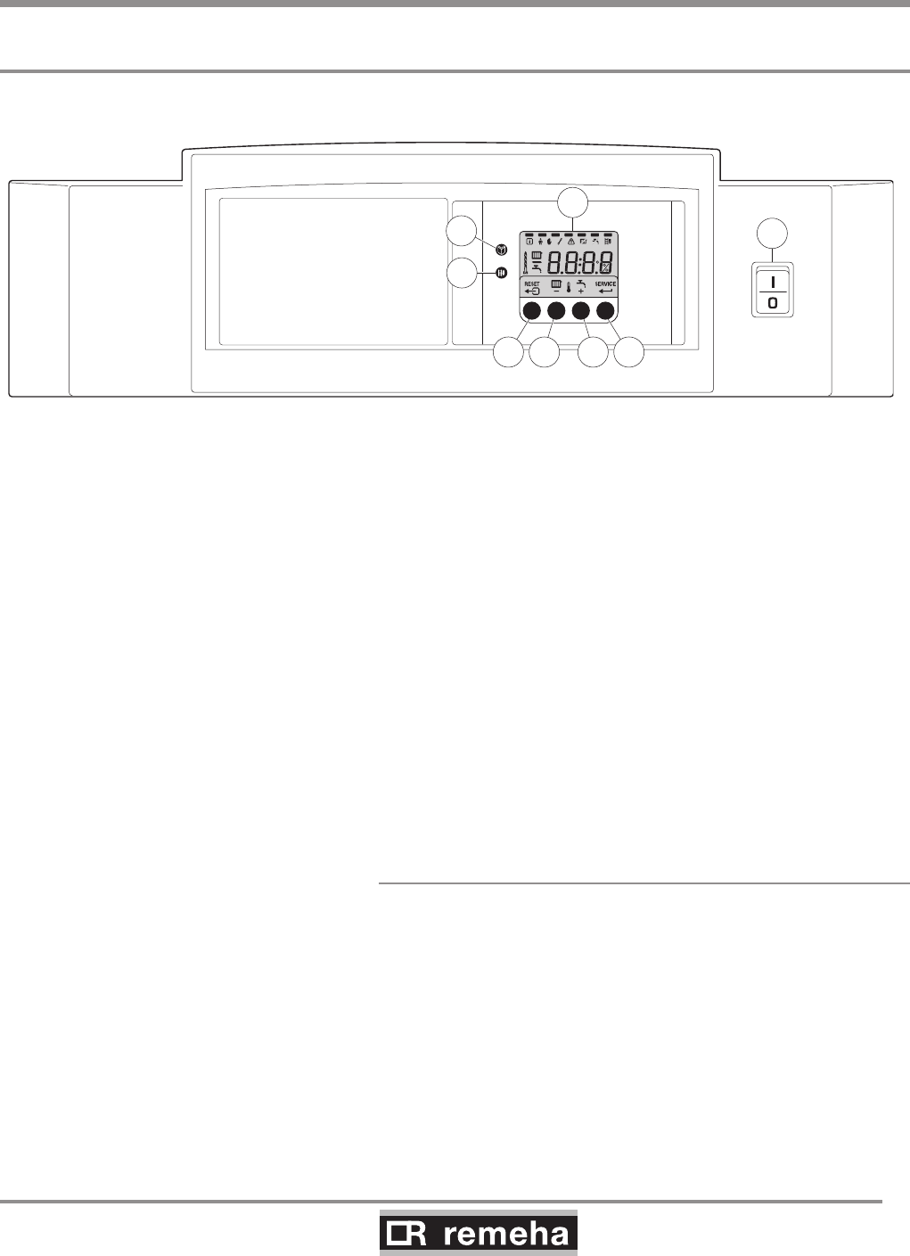
9.1 Control panel
The boiler's control panel contains four function keys, a menu key,
a service engineers key, an on/off switch and a display.
Bar
114492LTAL21H008a
2
3
4 5
1
8
6 7
fig. 17 Control panel
1 = Display 5 = [Central heating temperature] or [-] key
2 = [Menu] key 6 = [+] key
3 = [Service engineers] key 7 = [enter] key or [Service] indicator
4 = [Escape] or [reset] key 8 = On/off switch
The display has four positions and several symbols and provides
information about the operating status of the boiler and any faults.
Numbers, dots and/or letters may be shown. The symbols in the
display above the function keys indicate what the function of the
relevant keys is at that moment. If no key is pressed for three min-
utes, the display lighting switches off and only the and sym-
bols are displayed. Press any key; the current boiler status and
the current operating code appear on the display. This is always
displayed in the event of a fault.
9.1.1 Normal start-up procedure
Switch on the mains supply to the boiler; the Gas 210 ECO PRO
will perform the start-up program.
The following will appear in succession in the display:
- a short display test, whereby all of the display's segments are
visible;
fXx software version alternating with 1;
pXx parameter version;
- Afterwards (depending on the operating status), the following
may appear on the display:
N : L (flashes) : live and nutral wires are wrongly connected; chan-
ge wires on the 230V terminal strip!

GAS 210 ECO PRO
32
114494-03
9. Commissioning
With a heat demand:
1 Boiler starts
2 Burner starts
3 Central heating operation; briefly in part load then in full load
When a heat demand ceases:
5 Burner stops
6 Boiler stops
0 Stand-by mode
table 10 Normal operation
9.1.2 Fault during start-up procedure
If nothing appears on the display, check:
- the connection of the mains lead;
- the main fuse in the instrument box (F = 6.3 AT, 230 V);
- the fuse on the control unit (F1 = 1.6 AT, 230 V);
- the mains voltage.
• A fault code in the display is recognised as follows: the fault
symbol appears and
the fault code flashes underneath it;
• The meaning of this fault code can be found in the fault table,
see Section 11.2.
• If possible, solve the fault first.
• Press the RESET key for 3 seconds to restart the Gas 210
ECO PRO.
If the display does not show RESET but SERVICE, the boiler must
be switched off and switched on again after 10 seconds before the
fault can be reset.
114494-03
GAS 210 ECO PRO
33
9. Commissioning
114492LTAL21H009c
bar
%
fig. 18 Reading current values
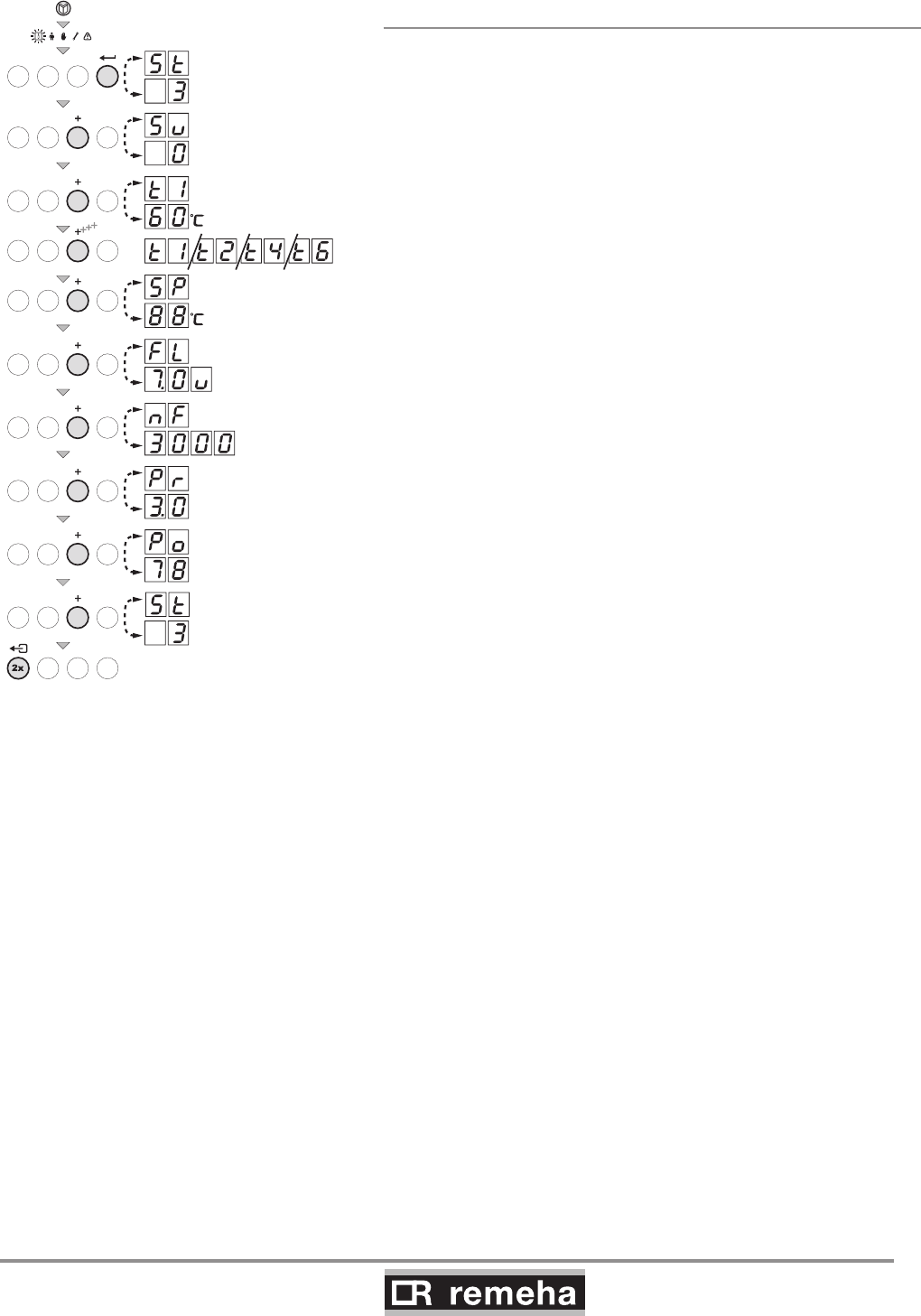
9.1.3 Reading current values
The following current values can be read in the ‘information
menu’
- 5t = Status
- 5u = Sub status
- t1 = flow temperature [°C];
- t2 = return temperature [°C];
- t4 = outside temperature [°C];
(only if outside sensor is connected)
- t6 = boiler block temperature [°C];
- 5p = internal set point [°C];
- fl = ionisation current [uA];
- f = fan rotation speed [rpm];
- pr = water pressure [mbar];
- p = relative output supplied [%];
The current values can be read as follows:
• Press the key, the symbol will then flash, confirm with
the key;
• Press the [+] key again so that 5t appears alternating with
3, the actual status;
• Press the [+] key again so that 5u appears alternating with
, the actual sub status;
• Press the [+] key again so that t1 appears, alternating with,
for example, 60°C, the actual flow temperature;
• Press the [+] key repeatedly so that the remaining temperatures
also appear;
• Press the [+] key again so that 5p appears, alternating with,
for example, 88°C, an internal set point;
• Press the [+] key again so that fl appears alternating with,
for example, u, the actual ionisation current;
• Press the [+] key again so that ñf appears alternating with,
for example, 3000 (rpm), the actual fan rotation speed;
• Press the [+] key again until pr appears alternating and, for
example, 3.0 bar, the actual water pressure
(if no water pressure sensor is connected, --.- bar appears);
• Press the [+] key again until p appears and, for example,
78 %, the actual modulation percentage;
• Press the [+] key again, the read-out cycle starts again with
5t, etc;
• Press the key twice to return to the display with the cur-
rent operating status.
GAS 210 ECO PRO
34
114494-03
9. Commissioning
9.1.3.1 Status and sub status
In the ‘information menu’ the following status and sub status
numbers are displayed:
Status 5t Sub status 5u
Number Status Number Sub status
0Stand-by mode 0Stand-by mode
1Boiler starts (heat demand)
1 Anti-hunting
2Open hydraulic valve
3Start pump
4Wait for the correct temperatures for burner start
2Burner starts
10 Open external gas valve
11 Fan running
12 Open flue gas damper
13 Pre-ventilation
14 Wait for release signal
15 Burner on
16 VPS gas leakage control
17 For ignition
18 Main ignition
19 Flame detection
20 Intermediate ventilation
3Burning on central heating operation
30 Temperature control
31 Limited temperature control (∆T safety)
32 Output control
33 Increase protection level 1 (control modulation)
34 Increase protection level 2 (part load)
35 Increase protection level 3 (shut down)
36 Modulate up for flame control
37 Stabilisation time
38 Cold start
5Burner stop
40 Burner off
41 Post ventilation
42 Fan running
43 Close flue gas damper
44 Stop fan
45 Close the external gas valve
6Boiler stop (end of heat demand)
60 Pump post circulation
61 Pump off
62 Close hydraulic valve
63 Start anti-hunting
8Control stop 0Wait for burner start
1 Anti-hunting
9 Shutdown xx Shutdown xx
table 11 Settings at service level
9.1.4 Adjusting the boiler to the system
The boiler's control parameters are set to the most common cen-
tral heating systems. With these settings, practically all central
heating systems will work well. However, the user or the installer
can optimise the parameters as he/she wishes.
114494-03
GAS 210 ECO PRO
35
9. Commissioning
9.1.6 Changing parameters at service level (with
access code)
To prevent undesired settings, some parameter settings can only
be changed after the special access code 12 is entered. This
code may only be used by qualified installers.
The following settings can be changed at user and service levels:
2x
2x
114492LTAL21H021b
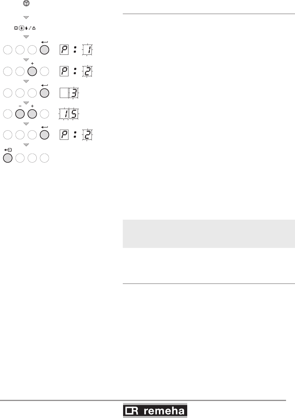
fig. 19 Changing parameters
9.1.5 Changing parameters at user level (without
access code)
The following settings can be changed at user level:
p1 = Flow temperature set point [°C], adjustable between 20
and 90°C;
p2 = Pump post-circulation time 0..98 mins, 99 is continuous;
p3 = Boiler control; central heating on/off.
0 = Central heating off
1 = Central heating on (= factory setting)
p4 = Display options
0 = Simple display
1 = Comprehensive display
2 = Display automatically goes to simple after three
minutes (factory setting)
* Consult our Technical department for further information and
demands on the system.
The parameters can be changed at user level as follows:
1. Press the -key several times until the symbol flashes in the
menu bar;
2. Select the users menu using the -key, p1 appears (the
1 flashes);
3. Press the [+]-key; p2 appears (the 2 flashes);
3. Press the -key again; 3 (min) appears and flashes: (fac-
tory setting);
4. Change the value by pressing the [-] -key or the [+] -key, in this
case for example to 15 min, with the [+] -key;
5.
Confirm the value with the -key, p2 appears (the 2 flashes);
6. Press the - key twice, the boiler enters the current operating
status.
The p1 to p4 settings can be changed in the same way as
p2.
GAS 210 ECO PRO
36
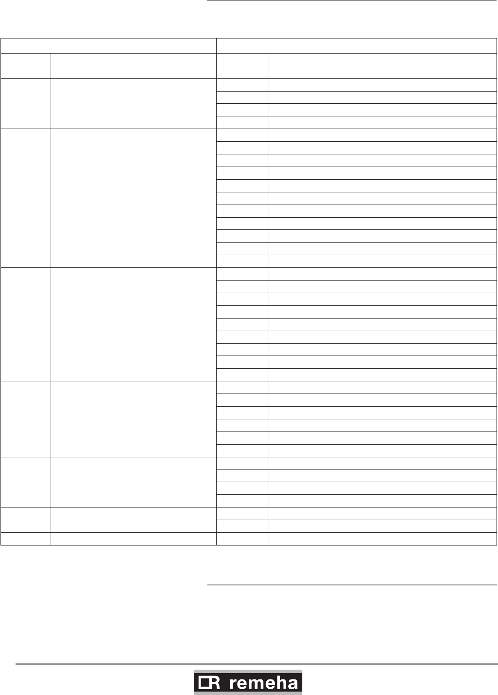
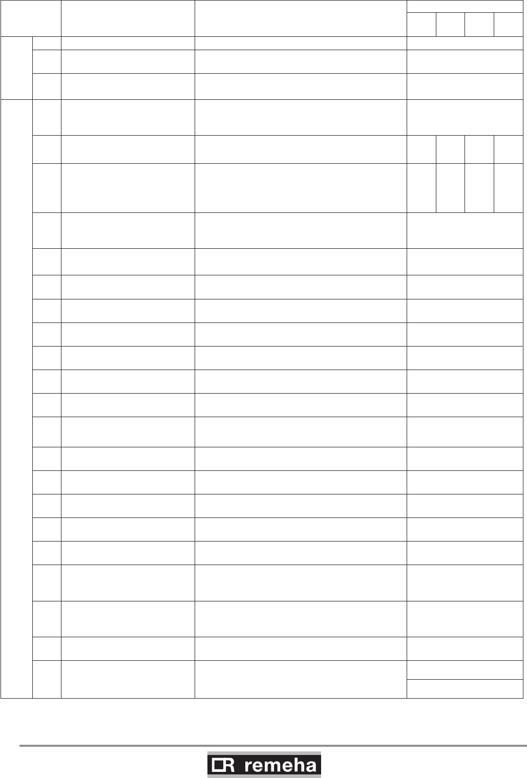
114494-03
9. Commissioning
Codes in
display Description Setting range and possible explanation
Factory setting
210-
80
210-
120
210-
160
210-
200
May also
be changed
by users
1Flow temperature set point 20 - 90°C 80
2Pump post-circulation time 0 – 98 minutes
99 = continuous 3
3Boiler control 0 = Central heating off
1 = Central heating on 1
Can only be changed by the installer
4Display
0 = Simple display
1 = Comprehensive display
2 = Display automatically goes to simple
2
17 Maximum speed
central heating (natural gas)
10 - 70
x 100 rpm 51 64 48 57
18
Minimum speed
central heating and hot water
(natural gas)
10 - 40
x 100 rpm
Do not change *
12 13 10 12
19 Starting speed
(natural gas)
10 - 40
x 100 rpm
Do not change *
17
20 Maximum flow temperature CH 20 - 90°C 90
21 Base point heating curve out-
side temperature 0 - 30°C (only with external sensor) 20
22 Baseline of flow temperature
heating curve 0 - 90°C (only with external sensor) 20
23 Outside temperature climate
point heating curve -30 - 0°C (only with external sensor) - 15
24 Outside temperature for frost
protection -30 - 0°C (only with external sensor) - 10
25 Fault relay function
(available as an accessory)
0 = Operation signal
1 = Alarm signal 1
26 Minimum water pressure
(available as an accessory)
1 - 60:10 bar (only with water pressure sensor)
0 = off 0
27 Minimum gas pressure check
(available as an accessory)
0 = Off
1 = On (only with a minimum gas pressure sensor) 0
28 Hydraulic valve running time
(available as an accessory)
0 = no waiting time
1 – 255 s (only if connected) 0
29 Flue gas damper running time
(available as an accessory)
0 = no waiting time
1 – 255 s (only if connected) 0
30 Maximum time for release 0 = no waiting time
1 – 255 s (only if connected) 0
31 VPS gas leakage control
(available as an accessory)
0 = off
1 = on (only with leakage control) 0
32 Mains detection phase 0 = Off
1 = On 0
33 External interlock function
(available as an accessory)
1 = Normal shutdown
2 = Shutdown without frost-protection
3 = Lock out
2
34 Display units
0 = °C / bar
1 = °F / psi
Do not modify
0
Ad Automatic detection of optional
hardware
0 = No
1 = Yes, once 0
df
and
dU
Resetting factory settings
The type plate states the value of
dF (X) and dU (Y); setting these values resets
the factory settings.
X
Y
table 12 Settings at service level
* Change this parameter when converting to flue gas cascade and LPG gas (please refer to Broag).
114494-03
GAS 210 ECO PRO
37
9. Commissioning
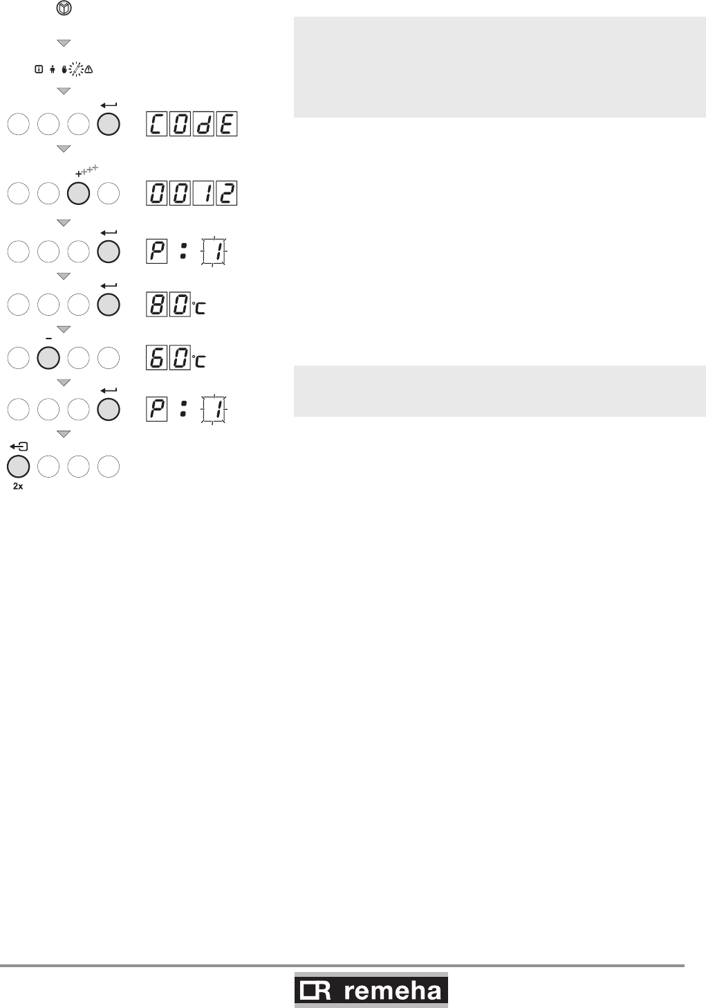
114492LTAL21H018b
4x
fig. 20 Setting service code
• The parameters at service level may only be changed by a
qualified installer.
• Changing the factory settings can result in incorrect operation of
the Gas 210 ECO PRO.
The parameters can be changed at service level as follows:
1. Press the -key several times until the symbol flashes in
the menu bar;
2. Select the installers menu using the -key,
appears in the display;
3. Use the [-] -key or [+] -key to set installers code 0012;
4. Confirm with the -key; appears;
5. Press the -key again; value 80°C appears (factory setting);
6. Lower the value, for example to 60°C, with the [-] key;
7. Confirm the value with the -key; appears;
8. Set other parameters where required by selecting them with the
[-] -key or [+] -key;
9. Press the - key twice, the boiler becomes operational.
Gas 210 ECO PRO also returns to operation if no keys are
pressed for 10 minutes.
GAS 210 ECO PRO
38
114494-03
9. Commissioning
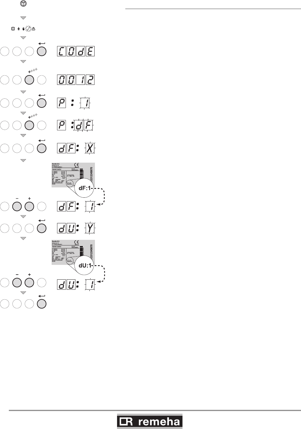
9.1.7 Resetting factory settings
• Press the -key several times until the symbol flashes in
the menu bar;
• Select the installers menu using the -key,
appears in the display;
• Use the [-] -key or [+] -key to set installers code 0012;
• Confirm with the -key; appears;
• Press the [+] -key several times, df X appears;
• By default, the current value X for dF appears on the display; as
a check, compare this with the
value of X on the type plate; enter the value of X on the type
plate with the [-] key or the [+] key.
• Press the key again, dU Y appears;
• By default, the current value Y for dU appears on the display;
as a check, compare this with the value of Y on the type plate;
enter the value of Y on the type plate with the [-] key or the [+]
key.
• Press the key to confirm the values; the factory settings
have been reset.
114492LTAL21H010a
4x
fig. 21 Resetting factory setting
114494-03
GAS 210 ECO PRO
39
9. Commissioning
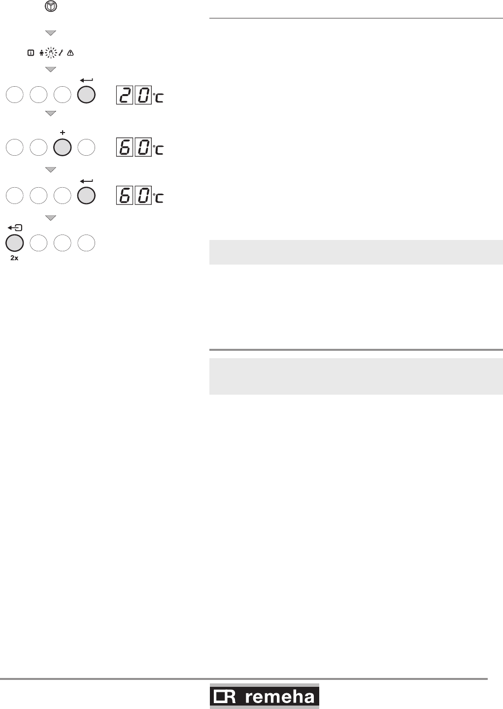
9.1.8 Setting manual operation ( symbol)
In some cases, it may be necessary to set the boiler to manual
operation, for example when the controller has not yet been con-
nected. The boiler can be set to automatic or manual operation
under the symbol. Do this as follows:
• Press the -key several times until the symbol flashes in the
menu bar;
• Press the -key once, either the minimum flow temperature
or AUt) (only if an external sensor
has been connected) will appear in the display; the flow
temperature is determined by the internal heating curve;
• or 20°C (minimum flow temperature) will appear in the display;
• Press the [+] -key to increase this value in manual operation
temporarily;
• Confirm with the -key;
• The boiler is now set to manual operation;
• Press the -key twice to exit manual operation; the boiler
enters operating status.
Manual operation keeps active after power breakdown.
114492LTAL21H019a
3x
fig. 22 Setting manual operation
9.2 Commissioning
Ensure that the boiler is disconnected from the power supply.
1. Remove front panel.
2. Open the main gas cock.
3. Check the electrical connections including earth.
4. Fill the boiler and the system with water
(minimum pressure 0.8 bar).
5. Vent the system.
6. Fill the trap with clean water.
7. Check the flue gas discharge connection and air supply
connection.
8. Vent the gas pipe (only vent pipework from
gas isolation valve).
9. Open the gas cock in the gas pipe to the boiler.
10. Check the gas connection for leakage.
11. Switch on the mains supply to the boiler.
12. Adjust the boiler and any external controls to heat demand.
13. The boiler now starts to run.
GAS 210 ECO PRO
40
114494-03
9. Commissioning
T000239-C
1
3
CO2
2
= full load
fig. 23 Setting values CO2
Operation can now be monitored via the code window:
With a heat demand:
1 Boiler starts
2 Burner starts
3 Central heating operation; briefly in part load then in full load
When a heat demand ceases:
5 Burner stops
6 Boiler stops
0 Stand-by mode
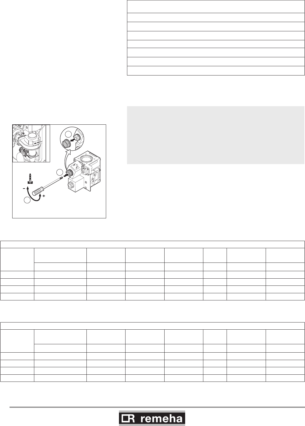
15 Check and, if necessary, correct the gas/air ratio control
setting.
Perform the check at full load and minimum load for all boiler
models. Only perform settings for the 210-80 and 210-120 models
at minimum load. Perform settings for the 210-160 and 210-200
models at full load and minimum load. An electronic CO2 or O2
meter is required for checking and adjustment purposes. Check
that the opening around the probe is properly sealed when meas
urements are taken.
15.a Set full load: press the key, the symbol appears in the
menu bar; if h3 appears in the display, full load has been set.
15.b Now measure the CO2 percentage and compare it with the
values in table 13. If the CO2% level deviates from these
values, set the CO2 percentage using the screw under the
cap of the V2 coil on the gas block (this can only be adjusted
on the 210-160 and 210-200 models). Check the flame
through the inspection glass (at full load): the flame must not
blow off and the burner's surface must not be red hot.
Checking and setting values O2/CO2 for natural gas (H) at full load
Boiler type Fan speed (rpm) CO2
Control
margin
Setting mar-
gin O2
Control
margin
Setting
margin
Full load h:3% % % % % %
210-80 5100 8.8 ± 0.7 n/a 5.2 ± 1.3 n/a
210-120 6400 8.8 ± 0.7 n/a 5.2 ± 1.3 n/a
210-160 4800 8.8 ± 0.5 ± 0.3 5.2 ± 0.9 ± 0.5
210-200 5700 8.8 ± 0.5 ± 0.3 5.2 ± 0.9 ± 0.5
table 13 Checking and setting values O2/CO2 for natural gas (front housing removed)
Checking and setting values O2/CO2 for natural gas (H) at minimum load
Boiler type Fan speed (rpm) CO2
Control
margin
Setting mar-
gin O2
Control
margin
Setting mar-
gin
Minimum load L:3% % % % % %
210-80 1200 9.3 ± 0.5 ± 0.3 4.3 ± 0.9 ± 0.5
210-120 1300 9.3 ± 0.5 ± 0.3 4.3 ± 0.9 ± 0.5
210-160 1000 9.3 ± 0.5 ± 0.3 4.3 ± 0.9 ± 0.5
210-200 1200 9.3 ± 0.5 ± 0.3 4.3 ± 0.9 ± 0.5
table 14 Checking and setting values O2/CO2 for natural gas (front housing removed)
114494-03
GAS 210 ECO PRO
41
9. Commissioning
114492LTAL21H027
.
8
4
H (G20)
Gas / Gaz / Gáz
ø 8.4 mm
fig. 26 Check size and positioning of restrictor
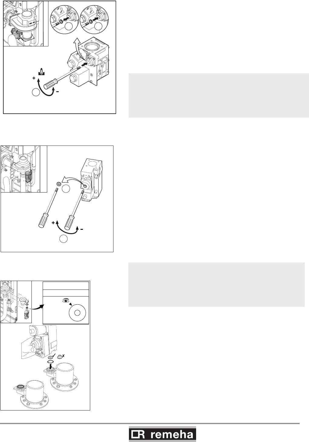
If the CO2% with the 210-80 and 210-120 still deviates on full load:
- adjust part load (see point 15.c and 15.d)
- check full load (see point 15.b) ; if the CO2% deviation is still too
large;
- check the size and placing of the restrictor (natural gas; 8.4 mm)
The following operating modes are now available:
23.a Modulating operation: The heat output of the boiler
modulates on the basis of the flow temperature demand-
ed by the modulating controller, see ‘Note’ in point 22
and Section 8.1.2.
23.b On/off operation: the boiler modulates between mini-
mum and maximum heat output on the basis of the flow
temperature set in the boiler, see Section 8.3.2.
T001791-B
2
CO2
1
3
= minimum load
114492LTAL21H020a
1
2
CO2
CO2
15.c Set minimum load: press the [-] -key and, when l 3
appears in the display, minimum load has been set.
15.d After minimum output has been reached, check the CO2
percentage and compare it with the value in table 14. If the
CO2% level deviates from these values, set the CO2
percentage using the correction screw of the pressure
controller on the gas block (for the 210-80 and 210-120
models, adjustments are only made at minimum load).
fig. 24 Setting values CO2 for 210-160 and
210-200
fig. 25 Setting values CO2 for 210-80 and 210-
120 (only minimum load)
The boiler is supplied with a number of basic settings.
burner control - modulating on the basis of flow temperature
maximum flow temperature - 80°C
If other values are required: see Section 9.1.6.
15.e Remove measuring equipment and seal measuring points.
16. Check gas leakage control (VPS if installed = available as an
accessory):
Then set the gas leakage control pressure switch to a switch pres-
sure equal to 50% of the inlet pressure. Check that the measured
inlet pressure is not the (higher) closing pressure.
17. Press the ‘reset’ key to reset the boiler to 'user level'.
18. Heat the system up to roughly 80°C if possible and switch
the boiler off.
19. Vent the system and check the water pressure.
20. The boiler is now ready for operation.
21. Set the boiler control to the required values and write down
the connected type of gas on the boiler type plate: e.g. G20
– 25 mbar.
22. Switch the boiler on.

GAS 210 ECO PRO
42
114494-03
9. Commissioning
9.3 Taking the boiler out of operation
The boiler must be switched off for maintenance or repair work. If
the central heating system is not going to be used for a long time
(for example, during holidays in frost-free periods), it is advisable
to put the boiler out of operation.
9.3.1 Boiler with frost protection, out of operation
for a long time
• Set the controller low, for example to 10°C;
The Gas 210 ECO PRO will now only come into operation to pro-
tect itself against freezing, (= depending on parameter 33, see
table 11).
To prevent radiators and the system from freezing in rooms where
there is a risk of frost (e.g. garage or storage room), a frost ther-
mostat can be connected to the boiler. The boiler will then keep
the radiators in that room warm.
This frost protection does not work if the boiler is out of operation.
9.3.2 Boiler without frost protection, out of
operation for a long time
• Isolate the mains power supply from the boiler;
• Close the boiler gas cock.
Drain the boiler and central heating system if you are not going
to use your home or the building for a long time and there is a
chance of frost.

114494-03
GAS 210 ECO PRO
43
10. Inspection and maintenance
10.1 General
The boiler is virtually maintenance free; it only has to be inspected
once a year and only if necessary be serviced/cleaned.
The annual inspection of the boiler includes:
- combustion check of the boiler (the fan draws in the
combustion air through the venturi. Clean the fan, venturi and
burner if there are irregularities);
- cleaning the trap;
- checking the ignition electrode;
- leakage check (water, flue gas and gas);
- water pressure check.
10.2 Combustion check of the boiler
Combustion is checked by measuring the O2/CO2 percentage in
the flue gas discharge duct. To do this, heat the boiler to a water
temperature of approx. 70°C. The measurements must meet
the values set in table 13. The flue gas temperature can also be
measured at the measuring point in the flue gas discharge duct. If
the flue gas temperature exceeds the return temperature by more
than 30°C, this can indicate that the heat exchanger is dirty.
If these checks show that combustion in the boiler or heat trans-
mission is no longer optimum, corrective maintenance must be
carried out in accordance with the instructions in Sections 10.2.1
to 10.2.4.
10.2.1 Corrective maintenance
This should include cleaning the fan, venturi, the heat exchanger
and the burner. These parts must be cleaned in succession.
A service kit which contains gaskets and most used parts for main-
tenance is available as an accessory.
Work on the boiler
Disconnect the mains supply, close the main gas cock and allow
the boiler to cool down before working on the boiler.
10. Inspection and maintenance
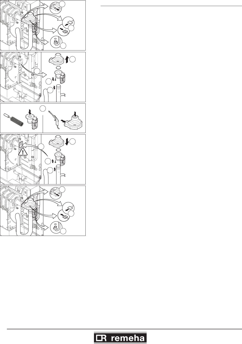
GAS 210 ECO PRO
44
114494-03
10. Inspection and maintenance
10.2.2 Cleaning the fan
For the 210-80 and 210-120 versions:
Remove the electrical connections from the fan.
1. Unscrew the union nut under the gas multiblock
(pay attention to the sealing).
2. Remove the bolts from the outlet side of the fan.
3. Remove the fan, including venturi and gas multiblock.
4. Remove the bolts on the inlet side of the fan.
5. Detach the venturi from the fan.
6. Clean the fan with a plastic brush.
7. Remove loose dust from the fan.
8. Re-attach the venturi to the fan.
9. Detach the air silencing tube from the venturi.
10. Clean the venturi with a plastic brush.
11. Refit all removed components; check the correct positioning of
the gasket ring between fan and venturi.
2
3
4
5
7
6
12
9
8
1
14
13
15
230 V
114492LTAL21H028b
230 V
11
10
fig. 27 Cleaning the fan 210-80 and 210-120
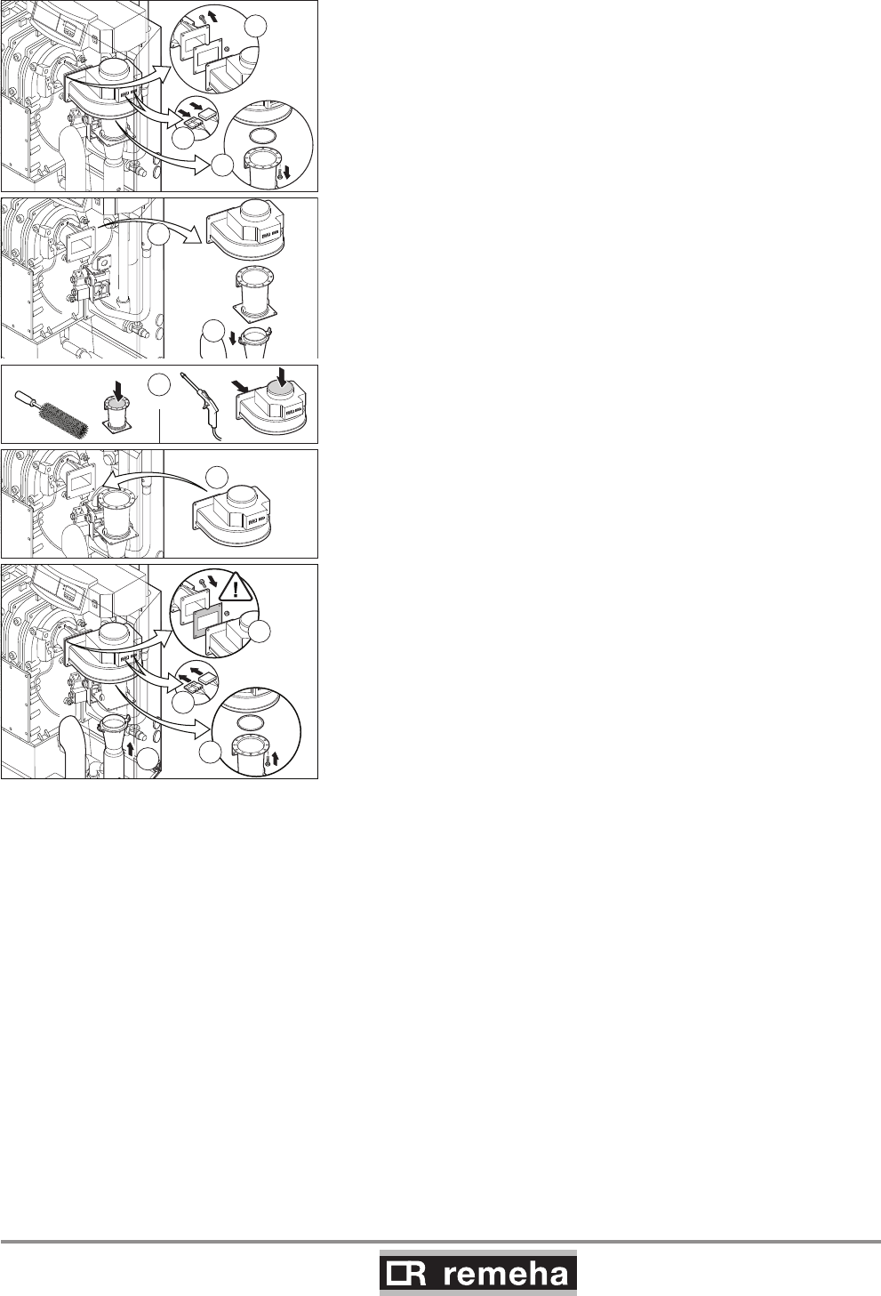
114494-03
GAS 210 ECO PRO
45
10. Inspection and maintenance
For the 210-160 and 210-200 versions:
1. Remove the electrical connections from the fan.
2. Remove the bolts that fix the venturi on the fan.
3. Remove the bolts and the nuts from the outlet side of the fan.
4. Remove the fan (pay attention to the sealing).
5. Clean the fan with a plastic brush.
6. Remove loose dust from the fan.
7. Detach the air silencing tube from the venturi.
8. Clean the venturi with a plastic brush.
9. Refit all removed components; check the correct positioning of
the gasket ring between fan and venturi.
7
2
3
114492LTAL21H029b
1
6
4
5
9
10
11
8
fig. 28 Cleaning the fan 210-160 and 210-200
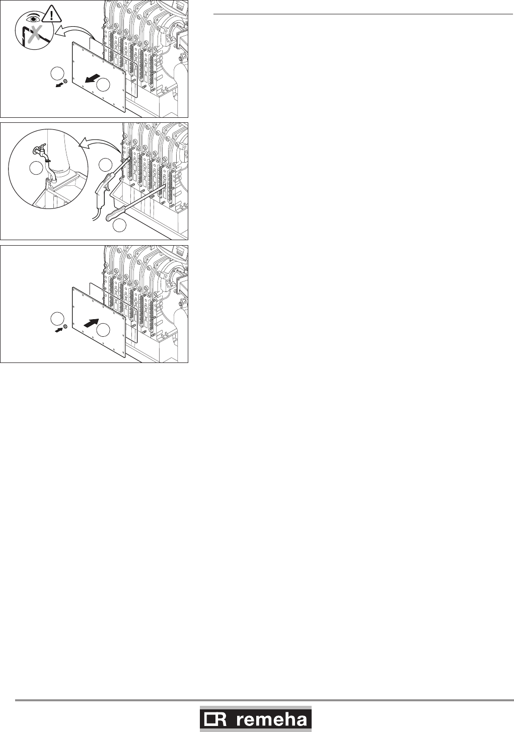
GAS 210 ECO PRO
46
114494-03
10. Inspection and maintenance
10.2.3 Cleaning the heat exchanger (flue gas side)
Caution: The sealing between the inspection hatch and heat
exchanger may stick, as may the sealing between the burner and
heat exchanger Prevent the sealing from tearing.
Damaged or hardened sealing must always be replaced.
1. Remove the nuts from the inspection hatch at the front of the
heat exchanger.
2. Take the inspection hatch off the heat exchanger.
3. Clean the heat exchanger with special cleaning tool (available
as an accessory) or compressed air.
4. Clean the condensate collector by removing the plug (in front of
the flue gas discharge pipe) and rinsing the collector with water.
5. Now refit all removed components.
5/6 leden
1
2
5/6 leden
6
5
4
5/6 leden
3
3
114492LTAL21H013a
fig. 29 Cleaning heat exchanger
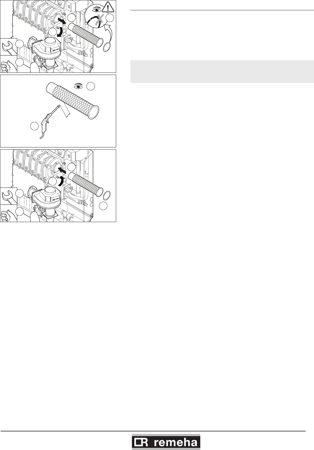
114494-03
GAS 210 ECO PRO
47
10. Inspection and maintenance
10.2.4 Cleaning the burner
1. Dismantle the burner.
2. Check burner visually and if necessary clean carefully with air
(e.g. compressed air at between 2 and 5 bar,
nozzle - burner distance approx. 1 cm).
3. Now refit all removed components.
Ensure that cables do not come into contact with hot boiler parts!
2
2
1
1
6
7
6
8
8
114492LTAL21H014a
4
5
1cm
2-5 bar
3
fig. 30 Cleaning burner
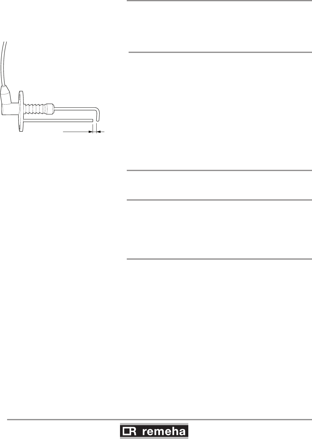
GAS 210 ECO PRO
48
114494-03
10. Inspection and maintenance
10.3 Cleaning the trap
Remove the trap from the boiler and clean it.
Fill the trap with fresh water and fit it.
10.4 Checking the ignition electrode
Check the ignition electrode adjustment (between 3 and 4 mm)
and replace electrode if necessary (including sealing). Also check
the electrode's porcelain for hairline fractures because this may
cause spark-over.
114492LTAL21H030
3 ... 4 mm
fig. 31 Check the ignition electrode 10.5 Checking for leaks
Check for water, flue gas and gas leaks.
10.6 Checking water pressure
The water pressure must be a minimum of 0.8 bar. The water
pressure also depends on the height of the central heating system
above the boiler (static pressure, 1 bar = 10 m high). It is recom-
mended to fill the system to approx. 0.8 bar above this static pres-
sure.
10.7 Putting boiler back into operation
1. Open the gas cock in the gas pipe to the boiler.
2. Switch on the mains supply to the boiler.
3. Adjust the boiler and any external controls to heat demand.
4. Perform another flue gas analysis (see Section 9.2 and adjust if
necessary.
114494-03
GAS 210 ECO PRO
49
11. Faults
11. Control stops and faults
11.1 General
The boiler is fitted with an advanced control unit. The heart of the
control is a microprocessor, the abc®, which both protects and
controls the boiler.
11.2 Control stops and faults
Control stop:
The control stop is a (temporary) boiler operating mode due to an
abnormal situation. The boiler switches to the neutral position so
that it can return to a normal state. The display then shows the
shutdown status (with code 9) again. The boiler control unit will, at
first, try several times to start the boiler again. The boiler shall oper-
ate again when the causes of the control stop have been removed.
Fault:
If the shutdown condition still exists even after various automatic
control unit start attempts have been made or if a non-reproduc-
ible phenomenon has arisen, the boiler switches to fault mode
(also known as lock-out). The boiler can only resume operation
if the cause of the fault is rectified and the ‘RESET button’ is
pressed
11.3 Control stop codes
The boiler display will show code 9.
The control stop codes can be read out as follows:
• Push the - key, and then the - key;
• The display shows = 9;
• Push the [+]- key one time; the display shows 5u and the
control stop code.
The boiler shall start automatically when the causes of the control
stop have been removed.

GAS 210 ECO PRO
50
114494-03
11. Faults
Code
5u Description Possible cause Check/solution
0Parameter fault • Reset dF and dU
• Reset with RECOM PC
1Maximum flow temperature
exceeded • No flow or insufficient flow
Check:
• Flow and/or reason
for heat demand
3Maximum heat exchanger tem-
perature exceeded
• No flow or insufficient flow
during heat demand
Check:
• Flow (direction, pump, valves)
• That the system has been correctly bled
• Temperature sensors for deviations
• Water pressure in the system
• Whether the heat exchanger is dirty
4Maximum heat exchanger tem-
perature increase exceeded
• No flow or insufficient flow
• Sensor fault
Check:
• Flow (direction, pump, valves)
• That the system has been correctly bled
• Temperature sensors for deviations
• Water pressure in the system
• Whether the heat exchanger is dirty
5
Maximum difference between
heat exchanger and return tem-
perature exceeded
• No flow or insufficient flow
during heat demand
• Sensor fault
Check:
• Flow (direction, pump, valves)
• That the system has been correctly bled
• Temperature sensors for deviations
• Water pressure in the system
• Whether the heat exchanger is dirty
6
Maximum difference between
heat exchanger and flow tem-
perature exceeded
• No flow or insufficient flow
during heat demand
• Sensor fault
Check:
• Flow (direction, pump, valves)
• That the system has been correctly bled
• Temperature sensors for deviations
• Water pressure in the system
• Whether the heat exchanger is dirty
8Waiting time release signal drift
• External cause
• Incorrectly set parameter
• Bad connection
• Remove external cause
• Check the parameter
• Check the connection
9Phase and neutral of mains sup-
ply mixed up
• Mains supply incorrectly wired
• Floating or 2-phase system
• Reconnect phase and neutral
• Set parameter 32 to 0
10 Shutdown interlock active
• External cause
• Incorrectly set parameter
• Bad connection
• Remove external cause
• Check the parameter
• Check the connection
11 Shutdown interlock active or frost
protection active
• External cause
• Incorrectly set parameter
• Bad connection
• Remove external cause
• Check the parameter
• Check the connection
13 Communication fault with SCU (=
optional PCB)
• BUS connection inadequate or
non-existent
• SCU PCB not present
(any longer) in boiler
• Reconnect
• Carry out automatic detection
14 Water pressure too low
• Water pressure non-existent or
too low
• Incorrect water pressure
parameter adjustment
• Water leakage
Check:
• Water pressure in the system
• Minimum water pressure
• That hydraulic pressure sensor is
properly installed /connected
15 Gas pressure too low
• No flow or insufficient flow
• Incorrect GPS switch
adjustment
• Wiring defect or switch faulty
Check:
• That the gas cock is fully opened
• That there is adequate gas pressure
• That the GPS switch is properly
installed
• Replace the GPS switch if necessary
16 *Configuration fault or SU
not recognised • Incorrect SU PCB for this boiler • Replace SU PCB
114494-03
GAS 210 ECO PRO
51
11. Faults
Code
5u Description Possible cause Check/solution
17 *Configuration fault or default
parameters table incorrect
• PCU-01 unit parameters
incorrect • Replace PCU-01 unit
18 *
Configuration fault or parameter
storage unit (PSU) not recog-
nised
• Incorrect PSU PCB for this
boiler • Replace PSU PCB
19 *Configuration fault or dF-dU
parameters unknown • Add/check dF and dU
20 *Configuration procedure active • Standard briefly activated
following boiler switch-on • No action
21 Communication fault with SU-01 • Bad connection • Check that the PCB is inserted in the
correct connector
22 No flame during operation • No ionisation current
Check:
• That the gas cock is fully opened
• That the gas pressure is sufficient
• That the gas block is appropriately
adjusted and working correctly
• Whether the air supply or flue gas
discharge are blocked
• The flue gas circulation; inspect the
flue gas discharge system for
installation faults and the heat
exchanger for leaks
24 VPS test failed
• Gas pressure non-existent or
too low
• Faulty gas valve
• Incorrect adjustment of the VPS
switch
• Wiring fault
• Faulty VPS switch
Check:
• That the gas cock is fully opened
• That the gas pressure is sufficient
• That the VPS switch is properly
installed
• Whether the gas valve is leaking or in
the open position
• That the wiring is OK; mix up of the V1
and V2 plugs
• The adjustment of the VPS switch
• Replace the VPS switch if necessary
• Replace the gas valve if necessary
25 Internal fault SU-01 • Replace SU-01
* These lock-outs are not stored in the failure memory.
table 15 Control stop codes
11.4 Fault codes
The boiler displays the fault codes as follows:
é 12 (the display shows the symbol and the fault code
flashes). The meaning of the fault codes can be found in the fault
table, see table 16.
In the event of faults, proceed as follows:
• Note the fault code.
The fault code is needed to find the cause of the fault quickly and
correctly and for any support from our Customer Care Department.

GAS 210 ECO PRO
52
114494-03
11. Faults
• Press the “RESET- key” for 2 seconds. If the fault code conti-
nues to appear, look for the cause in the
following fault table and rectify the fault.
If the display does not show RESET but SERVICE, the boiler must
be switched off and switched on again after 10 seconds before the
fault can be reset.
Fault
code Description Possible cause Check/solution
E:00 Storage unit parameter not
found • Bad connection • Check the cable bundle
E:01 Safety parameters not in
order • Bad connection • Check the cable bundle
E:02 Heat exchanger temperature
sensor short circuited
• Bad connection
• Defective sensor
• Sensor not correctly mounted
• Check the cable bundle
• Replace the sensor if necessary
• Check if sensor is correctly mounted
E:03 Heat exchanger temperature
sensor open circuit
• Bad connection
• Defective sensor
• Sensor not correctly mounted
• Check the cable bundle
• Replace the sensor if necessary
• Check if sensor is correctly mounted
E:04
Heat exchanger tempera-
ture exceeded below normal
range • Bad connection
• Defective sensor
• Sensor not correctly mounted
• No or to little flow
• Check the cable bundle
• Replace the sensor if necessary
Check:
• flow (direction, pump, valves)
• if system has been correctly bled
• temperature sensors for deviations
• if sensor is correctly mounted
• water pressure in the system
• if heat exchanger is dirty
E:05
Heat exchanger temperature
exceeded above normal
range
(high limit thermostat)
E:06 Return temperature sensor
short circuited
• Bad connection
• Defective sensor
• Sensor not correctly mounted
• Check the cable bundle
• Replace the sensor if necessary
• Check if sensor is correctly mounted
E:07 Return temperature sensor
open circuit
• Bad connection
• Defective sensor
• Sensor not correctly mounted
• Check the cable bundle
• Replace the sensor if necessary
• Check if sensor is correctly mounted
E:08 Return temperature exceed-
ed below normal range • Bad connection
• Defective sensor
• Sensor not correctly mounted
• No or to little flow
• Check the cable bundle
• Replace the sensor if necessary
Check:
• flow (direction, pump, valves)
• if system has been correctly bled
• temperature sensors for deviations
• if sensor is correctly mounted
• water pressure in the system
• if heat exchanger is dirty
•
E:09 Return temperature exceed-
ed above normal range
E:10
E:11
Too great a difference
between heat exchanger and
return temperature
• Defective sensor
• No or to little flow
• Sensor not correctly mounted
• Replace the sensor if necessary
Check:
• flow (direction, pump, valves)
• if system has been correctly bled
• temperature sensors for deviations
• water pressure in the system
• if heat exchanger is dirty
• if sensor is correctly mounted

114494-03
GAS 210 ECO PRO
53
11. Faults
Fault
code Description Possible cause Check/solution
E:12 Trap protection activated
• Bad connection
• Pressure in flue gas discharge duct
is (was) too high
• air supply obstructed
• Check the cable bundle
• Check that the trap is not empty; top up
if necessary
• Blockage in flue gas discharge/RGA
covered
• Cascade valve does not open
• Trap is blocked
• Heat exchanger is dirty
• check the air supply
E:14 5 failed burner starts
• No ignition spark
Check:
- connection between ignition cable and
transformer
- electrode distance, this must be 3 to 4 mm
- breakdown to earth
- condition of the burner set
(burner set/electrode seal)
- earthing
- bad actuation on SU board
• Ignition spark, but no flame
Check:
- is the gas cock opened?
- is the inlet gas pressure sufficient?
- is the gas pipe vented?
- correct gas block operation and
adjustment?
- is the air supply or flue gas discharge
blocked?
- condition of cable bundle to gas block
- bad actuation on SU board
• Flame, but insufficient ionisation
Check:
- condition of the electrode and earthing
- condition of cable bundle between ignition
cable and transformer
- if gas cock is fully opened
- if the gas pressure is sufficient
E:15 5 failed gas leakage controls
• Defective gas valve
• No or to little gas pressure
• VPS switch wrongly adjusted
• Bad connection
• Defective sensor
• Sensor not correctly mounted
• Is the gas cock opened?
• Is the gas pressure sufficient?
• Are the VPS switches correctly fitted?
• Gas valve is leaking or is stuck in the
open position.
• Is the wiring in order, plugs V1, V2 not
mixed up?
• Check the VPS settings
• Replace the sensor if necessary
• Check if sensor is correctly mounted
E:16 False flame signal
•
Ionisation current has been meas-
ured, while there may not be a flame
• Defective ignition transformer
• Burner glows as a result of a high CO2
percentage (adjust CO2).
• Check the ignition/ionisation electrode
• Gas valve is leaking or is stuck in the
open position.
• Replace ignition transformer
E:17 Gas valve control fault • Bad connection
• Defective gas valve
• Check the cable bundle
• Replace the gas valve if necessary
E:32 Flow temperature sensor
short circuited
• Bad connection
• Defective sensor
• Sensor not correctly mounted
• Check the cable bundle
• Replace the sensor if necessary
• Check if sensor is correctly mounted

GAS 210 ECO PRO
54
114494-03
11. Faults
Fault
code Description Possible cause Check/solution
E:33 Flow temperature sensor
open circuit
• Bad connection
• Defective sensor
• Sensor not correctly mounted
• Check the cable bundle
• Replace the sensor if necessary
• Check if sensor is correctly mounted
E:34 Fan fault • Bad connection
• Defective fan
• Fault in fan cabling
• Defect in fan
• (Too) much draught over boiler, so that
the fan starts to rotate
E:35 Flow and return swopped
• Defective sensor
• Wrong flow direction
• Bad sensor connection
• Sensor not correctly mounted
Check:
- flow direction
- temperature sensors for deviations
• Replace the sensor if necessary
E:36
Flame loss occurs 5 times • Ionisation current drops out
• Inlet gas pressure sufficient? Inlet gas
pressure controller in order?
• Correct gas block operation and
adjustment?
• Blockage in air supply or flue gas
discharge?
• Flue gas circulation, check flue gas
system for installation faults and the
heat exchanger for possible leaks
E:37
Communication fault with SU
board • Bad connection • Check SU board is correctly inserted in
the connector on the PCU-01
E:38
Communication fault with
SCU board (optional) • Bad connection • Check the cable bundle
E:39
Shutdown input in locked-out
mode
• External cause
• Incorrectly set parameter
• Bad connection
• Remove external cause
• Check the parameter
• Check the cable bundle
table 16 Fault codes
11.5 Control stop - and fault memory
The boiler control unit has a control stop and fault memory. This
stores the last 16 control stops and the last 16 faults that have
occurred.
With each fault, the following data is saved:
- B or E = control stop or fault code
- = Number of times that the fault has occurred
in succession
- hr = Burner operating hours since time of fault
- 5t = status
- 5u = sub status
- t1 = flow temperature [°C];
- t2 = return temperature [°C];
- t4 = outside temperature [°C];
- t6 = boiler block temperature [°C];
- 5p = internal set point [°C];
- fl = ionisation current [uA];
- f = fan rotation speed [rpm];
- pr = water pressure [mbar];
- p = relative output supplied [%];
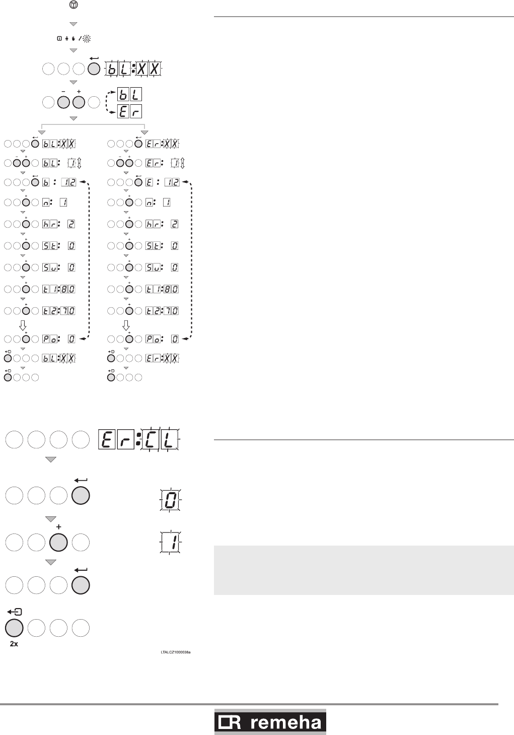
114494-03
GAS 210 ECO PRO
55
12. Service parts
11.5.1 Reading faults
• Press the -key several times until the symbol flashes in
the menu bar;
• Press the key; B- xx will flash in the display, together
with the number of shutdowns that have been memorised;
• Press the [+] or [-] key to select either the control stops B- or
faults Er.
• Press the key; B- xx will flash in the display, together
with the number of shutdowns that have been memorised;
• Press the [+] or [-] -key to go forwards or backwards in the list
of faults.
• Press the -key to take a closer look at the fault.
Press the [+] or [-] -key to view the following information:
b12 (shut down code b with fault number e.g. 12);
(number of with the 'number of times that the fault has
occurred’ as number);
hr = 2 (burner operating hours since time of fault) ; (sta-
tus code) ; 5u (sub status);
t180 (temperature t1, the flow temperature 80 when
the fault occurred);
t270 (temperature t2, the return temperature 70
when the fault occurred);
• Press the -key to stop the cycle, B- xx will appear
flashing in the display with the number of the last fault;
•
Press the [+] or [-] -key to view any subsequent fault information.
5x
114492LTAL21H015a
t/m t/m
2x 2x
fig. 32 Reading faults or control stops
11.5.2 Deleting control stops or faults
The last message in the list in the display is - (or
b-- with shutdowns)
• Press the -key; the display will show: 0
• Press the [+] -key to set the parameter to 1.
• Press the -key ; the fault memory is cleared
• Press the - key twice to exit the fault memory.
fig. 33 Deleting faults
With faultfinding, retrieving the operating status when the fault
occurred can contribute to faster rectification of the cause.
GAS 210 ECO PRO
56
114494-03
12. Service parts
12. Service parts
12.1 General
If it is ascertained during the annual inspection or maintenance
work that a part in the boiler must be replaced, use only original
parts or parts and materials recommended by Broag.
Send the part to be replaced to Broag. Always send a fully com-
pleted return form as well, see example. In this way, Broag can
handle its guarantee obligations faster and more efficiently.
Your reference Date
Customer
Name
Address
Zip code / city
Telephone
Contact person
Job number
Part. no. Description Boiler
serial nr.* Model Installation
date
Problem des-
cription Reference
t
able 17 Return form sample
* This data can be found on the boiler type plate; the type plate is stuck to the top of the boiler's right side panel.
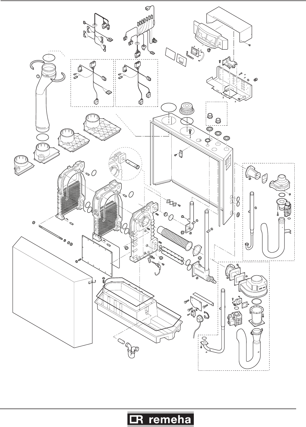
114494-03
GAS 210 ECO PRO
57
12. Service parts
12.2 Exploded view
fig. 34 Exploded view
210-200
210-200
210-160
210-200
210-80
210-120
210-120
210-80
210-200
210-160
210-200
210-160
210-120
210-80
114492EVAL21H001b

GAS 210 ECO PRO
58
114494-03
13. Regulations
13. Regulations
13.1 General
The Remeha Gas 210 ECO PRO is a high efficiency, floor stand-
ing central heating boiler, suitable for use with all types of natural
gas; it recovers both perceptible and latent heat from flue gases.
The units are inspected on the basis of the essential requirements
in the following directives:
- Gas Appliances Directive no. 90/396/EEC
- Efficiency Requirements Directive no. 92/42/EEC
- EMC Directive no. 89/336/EEC
- Low Voltage Directive no. 73/23/EEC
- Pressure Equipment Directive no. 97/23/EEC, article 3, sub. 3
CE identification number: 0085BS0132
NOx class: 5
NOx identification number: BS004
13.2 Standards
The following instructions must be adhered to when the Remeha
Gas 210 ECO PRO is installed:
- Gas Safety (Installation and Use) Regulations 1998 (as amended).
In addition to the above regulations, this boiler must be installed
in compliance with:
- Current I.E.E. Regulations for electrical installations
- Local building regulations
- The Building Standards (Scotland)
- (Consolidation) Regulations
- by-laws of the local water undertaking
- Health and Safety Document No 635 'The Electricity at Work
Regulations 1989'.
It should also be in accordance with the relevant recommendations
in the current edition of the following British Standards and Codes
of Practice, viz. BS 6644, BS 5978 Part 1 & 2, BS 5449, BS 5446,
BS 6798, BS 6891 and BG DM2.
13.3 Remeha factory test
Before leaving the factory, every Remeha boiler is optimally set
and tested for:
- electrical safety;
- CO2 adjustment;
- hot water operation;
- water tightness;
- gas tightness;
- control unit parameters.

114494-03
GAS 210 ECO PRO
59
13. Regulations
13.4 Supplementary guidelines
In addition to the regulations and guidelines mentioned in Section
13.2, the supplementary guidelines in this documentation must
also be followed. Supplements or subsequent regulations and
guidelines in existence at the time of installation shall apply to all
regulations and guidelines mentioned in this Installation and Serv-
ice manual.
The Remeha Gas 210 ECO PRO is a CE certified boiler and must
not be modified or installed in any way contrary to these
"Installation and Maintenance Instructions". Manufacturers
Instructions must NOT be taken as overriding statutory obligations.
GAS 210 ECO PRO
60
114494-03
14. Technical specifications
14. Technical specifications
14.1 Technical data
Boiler type Gas 210 ECO PRO Unit 210-80 210-120 210-160 210-200
General
Number of sections 3456
Input control -Modulating, 0-10 V or on/off
Nominal output (80/60°) Pn min kW 16 22 29 39
max kW 87 120 166 200
Nominal output (50/30°) Pn min kW 18 24 33 44
max kW 93 129 179 217
Nominal input gross caloric value
(GCV/Hs) Qn
min kW 19 26 34 46
max kW 99 137 189 228
Nominal input net caloric value
(NCV/Hi) Qn
min kW 17 23 31 41
max kW 89 123 170 205
Gas and flue gas side
Category - II2H3P
Inlet gas pressure natural gas mbar 17 - 30
Gas consumption natural gas min m0
3/h 1.8 2.4 3.3 4.3
max m0
3/h 9.4 13.0 18.0 21.7
NOX emission per year (BREEAM)
(EN 15420) mg/kWh 33 35 38 37
Residual fan pressure Pa 130 130 130 130
Flue gas quantity min kg/h 27.2 36.7 49.5 65.5
max kg/h 149.7 206.9 286.0 344.9
Type classification with respect to flue gas
discharge -B23, B23P
, C13, C33, C43, C53, C63, C83
Central heating side
High limit temperature °C 110
Operating temperature range °C 20 - 90
Minimum water working pressure bar 0.8
Maximum water working pressure PMS bar 6
Water content litres 12 16 20 24
Hydraulic resistance at dT = 20°mbar
(kPa)
165
(16.5)
135
(13.5)
170
(17)
180
(18)
Electrical
Mains voltage V/Hz 230/50
Input power
(without pump)
min Watt 4 4 4 4
max Watt 125 193 206 317
Insulation class IP 20
Other
Weight excluding water kg 115 135 165 188
Noise level at a distance of 1 m from the
boiler (enclosed version) dB(A) ≤ 59
Environment temperature °C 0 - 40
Colour of casing RAL 2002 (red)/7037 (grey)
table 18 Technical data

114494-03
GAS 210 ECO PRO
61
15. Efficiency data and gas inspection labels
15. Efficiency data and gas inspection labels
15.1 Unit usable efficiency (HR efficiency)
Up to 108.6 with respect to Hi at TReturn = 30°C.
15.2 Water-side efficiency
a. Up to 98.4% with respect to Hi at full load at an average water
temperature of 70°C (80/60°C).
b. Up to 105.7% with respect to Hi at full load an average water
temperature of 40°C (50/30°C).
15.3 Zero-load losses
Approx. 0.21% with respect to Hi at an average water temperature
of 45°C.
15.4 Description of specifications
High efficiency gas boiler
Inspected for compliance with the essential requirements of the
Gas Appliances Directive, Efficiency Directive, Low Voltage Direc-
tive and EMC Directive.
- Boiler conforms to Pressure Equipment Directive (article 3, sub. 3).
- Modulating (18 - 100%) or 0-10V or on/off control is optional.
- Hydraulic efficiency up to 98.4% at full load (with respect to Hi)
at 80/60°C and up to 105.7% (with respect to Hi) at 50/30°C.
- Suitable for use with II2H3P
- Annual NOX emissions < 62 mg/kWh, or < 35 ppm at O2 = 0%
(NOx - class 5).
- Average boiler housing noise level at 1 m distance around
boiler ≤ 59 dBA
- Heat exchanger made of cast aluminium sections.
- Cylindrical, stainless steel, premix burner with metal fibre cover.
- Air supply fan.
- Flue gas pressure difference switch.
- Temperature control: adjustable between 20 - 90°.
- Low water level protection using temperature sensors.
- Gas/air mixing system (venture).
- Gas multiblock (210-80 + 210-120 ;230V) (210-160 + 210-200;
30 RAC)
- Electronic control and protection equipment: 230 V.
- Fan; 230V
- Pump switch: on/off 230 V max. 300 VA.
- Frost protection.
- Filling and drain cock.
- Trap.
- Suitable for both room ventilated and room sealed versions.
- Sheet steel casing, off the ground.
- Plastic condensate collector.
- Boiler equipped with closed air box.
- Boiler fully pre-wired with built-on control box.
- Installation option for boiler controllers.
- Suitable for OpenTherm controllers.
- Supplied with internal heating curve.
- Well laid-out instrument panel with LCD display.
- Menu-controlled microprocessor boiler control with operating
and servicing diagnostics.

GAS 210 ECO PRO
62
114494-03
15. Efficiency data and gas inspection labels
Available in 4 types:
210 -80: 87 kW nominal output at 80/60°C
210-120: 120 kW nominal output at 80/60°C
210-160: 166 kW nominal output at 80/60°C
210-200: 200 kW nominal output at 80/60°C
15.5 Accessories
- Modulating rematic® weather compensators.
- OpenTherm weather compensators (iSense), also for cascade
configurations (Celcia MC4).
- Air supply filter (only for use with “open flue”).
- Concentric wall and roof feed-through connections.
- Second return connection (for CT circuit).
- Thermostat pocket
- Cleaning tools.
- Service case.
- Recom communication set with CD-ROM, interface and wiring.
- Interfaces for communication with various controllers, see Sec-
tion 8.4.3.
- 0 - 10 V control PCB (IF-01).
- Expanded control/protection PCB (SCU-S01).
- Outside temperature sensor* (only possible in combination with
SCU-S01 PCB).
- Flue gas temperature switch* (only possible in combination with
SCU-S01 PCB).
- Minimum gas pressure switch* (only possible in combination
with SCU-S01 PCB).
- Water pressure sensor* (only possible in combination with SCU-
S01 PCB).
- Motorised flue gas discharge valve* for cascade configurations
and to prevent flue gas from flowing back (only possible in com-
bination with SCU-S01 PCB).
- Gas leakage control* (for the 166 and 200 kW boilers), only
possible in combination with SCU-S01 PCB.
* Only one PCB (SCU-S01) board is needed for one or all of these
options.
15.6 Services
The following services can be supplied by Broag:
- Initial commissioning.
- Warranty support.
- Access to list of Broag trained and approved service companies.
Please contact our Technical department for further information on
certified maintenance and inspections.
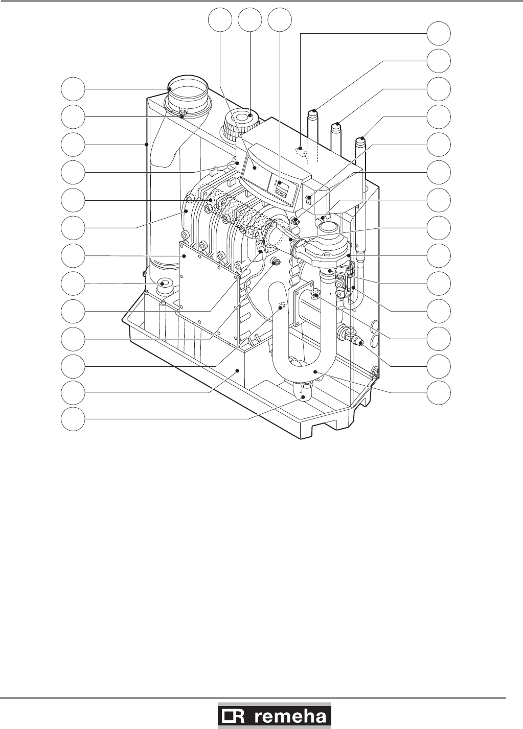
114494-03
GAS 210 ECO PRO
63
15. Efficiency data and gas inspection labels
15.7 Type of unit
fig. 35 Cross-section
26
27
21
19
9
15
16
17
18
20
13
12 14
25
24
23
22
1
30 2829
2
3
5
4
7
8
6
10
11
114492LTAL21H016b
1. Flue gas discharge 11. Return temperature sensor 21. Flue gas switch
2. O2/CO2 measuring point 12. Condensate collector 22. Flow temperature sensor
3. Air box 13. Condensate trap 23. On/off
4. Control panel 14. Air silencing tube 24. Gas connection
5. Burner 15. Filling and drain cock 25. Return connection
6. Heat exchanger 16. Water pressure switch (option) 26. Flow connection
7. Inspection hatch 17. Gas multiblock 27. Thermostat pocket
8. Inspectionhatch for condensate collector 18. Venturi 28. Display
9.Ignition pin 19. Fan 29. Combustion air supply
10. Boiler heath exchanger sensor 20.Mixing tube 30. Facility for built-in weather compensator

GAS 210 ECO PRO
64
114494-03
15. Efficiency data and gas inspection labels
15.8 Operating principle
The inlet side of the fan is fitted with a venturi, where air and gas
are mixed according to a fixed ratio. When there is a heat demand,
the fan will pre-vent. The fan draws in the combustion air, which is
mixed with the gas to optimum effect in the venturi. The fan moves
the homogenous gas/air mixture through to the burner. The mixture
is then ignited by the combined ignition and ionisation electrode,
which also monitors the flame. Combustion then takes place. Fol-
lowing combustion, the hot flue gases pass through the cast alumin-
ium heat exchanger. Here, the flue gases release their heat to the
heating water in the heat exchanger. The heat output of the boiler is
controlled on the basis of the settings and the prevailing water tem-
peratures that are measured by the temperature sensors. With flue
gas temperatures below dew point (approx. 55°, the temperature at
which the water vapour in the flue gases starts to condense), the
water vapour in the flue gases will condense in the lower part of the
heat exchanger. The heat released during this condensation proc-
ess (called latent heat or heat of condensation) is also transferred
to the heating water. The condensed water is discharged through a
trap. The flue gases flow through the condensate collector and are
discharged via the flue gas discharge pipe.
The advanced control system of the boiler, the abc®, guaran-
tees extremely reliable heat supplies. This means that the boiler
responds quickly and efficiently to negative environmental influ-
ences (such as hydraulic flow problems, air flow problems, etc.). If
problems of this kind occur, the boiler will not lock out, but initially
modulate down and, depending on the nature of the problem,
switch off temporarily (shutdown or control stop) and try again
after a pre-determined time. Providing the situation is not hazard-
ous, the boiler will always continue to attempt to provide heat. For
a continuous supply of heat, the boiler requires a minimum flow of
30 % of the nominal flow at the relevant design temperatures. The
boiler can be equipped with a second return for CT circuit (avail-
able as an accessory). The second return can contribute additional
efficiency if the installation includes different temperature groups.
15.9 Boiler Control
15.9.1 Temperature control
The Remeha Gas 210 ECO PRO is equipped with electronic tem-
perature control based on flow, return and boiler block temperature
sensors. The flow temperature is adjustable between 20 and 90°C
(factory setting 80°C).
15.9.2 Low water level protection
The Remeha Gas 210 ECO PRO is equipped with low water pro-
tection based on temperature difference measurements and tem-
perature increase measurements.

114494-03
GAS 210 ECO PRO
65
15.9.3 Maximum protection
The maximum protection switches the unit off if the water tempera-
ture is too high (110°C) and interlocks it on the control box. Once
the fault has been remedied, the unit can be reset using the reset-
key.
15.9.4 Frost protection
The unit must be installed in a frost-free area to prevent freezing
of the condensate drain pipe. If the temperature of the heating
water drops too much, the built-in unit protection activates.
15. Efficiency data and gas inspection labels

GAS 210 ECO PRO
66
114494-03
16. Application data
16. Application data
16.1 General
The boiler is suitable for a wide range of applications. The boiler
offers numerous flue gas, hydraulic, gas and control applica-
tion options, but, at the same time, is not complicated to install.
This and its moderate dimensions, low noise levels and cascade
options mean the boiler can be installed almost anywhere (for
general legal requirements, see Section 13.2).
16.2 Air and flue gas application options
The choice of versions (open or closed combustion air supply)
provides excellent siting flexibility for the boiler. A motorised flue
gas discharge valve is available as an accessory and is used for
overpressure flue gas cascade arrangements.
The boiler is equipped with an enclosed housing that also serves
as an air box. An air filter and connection set are available for situ-
ations in which the boiler has to be commissioned during the con-
struction phase or has to operate in a heavily polluted environment
(this only applies to room ventilated versions).
Direct connection to structural ducts is not acceptable because
of condensation, see Chapter 7 for instructions and flue gas dis-
charge tables.
16.3 Hydraulic application options
The advanced boiler control (abc®) and relatively low hydraulic
resistance ensures that the boiler can be used in virtually any
hydraulic system.
16.4 Cascade application
The boiler is also suited for configuration in a cascade. For over-
pressure flue gas cascade arrangements, use our motorised flue
gas discharge valve (available as an accessory). This prevents
flue gas from flowing back to boilers that are not in operation. As a
result of the narrow width and depth of the boiler, a heat output of
400 kW (2 x Gas 210- 200) can be provided in a floor area of just
under 1.2 m2. A floor area of less than 3 m2 is sufficient to include
room for service and maintenance. If necessary, consult our Tech-
nical department.
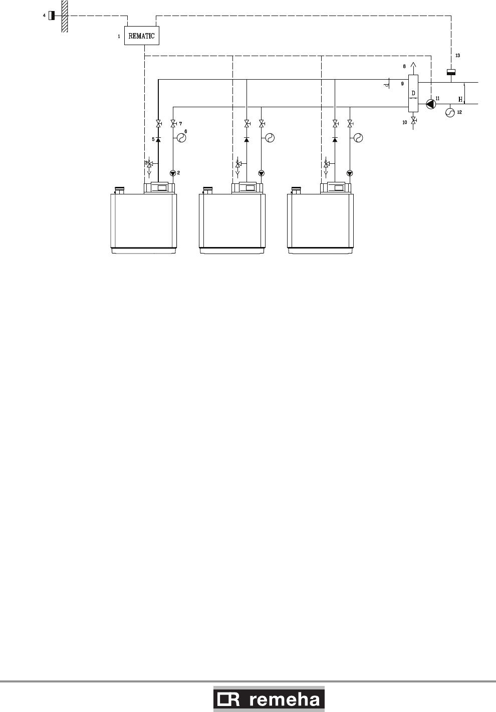
114494-03
GAS 210 ECO PRO
67
16. Application data
fig. 36 Example of a hydraulic diagram cascade configuration
1. modulating cascade controller 8. automatic air vent
2. pump 9. pressure-free distributor (not supplied by Remeha, see table 19 for dimensions)
3. safety valve 10. drain cock
4. outside temperature sensor 11. system pump
5. non return valve 12. expansion vessel system
6. expansion vessel 13. flow temperature sensor
7. manual seal
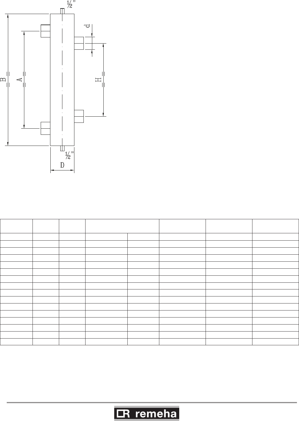
GAS 210 ECO PRO
68
114494-03
16. Application data
B I The following table shows the minimum dimensions for the various
pipes and for the low loss header based on a dT design of 20°.
The boiler has a no built-in pump.
fig. 37 Illustration of low loss header
B = boiler side
I = installation side
Output Rate of
flow Q d int. D Ø or D square H A B
kW m3/h inch inch mm mm mm mm
80 3.4 1¼ 3 (DN 80) 70 280 370 510
120 5.2 2 4 (DN 100) 90 350 465 630
160 6.9 2 4 (DN 100) 100 350 465 630
200 8.6 2½ 5 (DN 125) 110 440 580 770
240 10.3 2½ 5 (DN 125) 120 440 580 770
280 12.0 2½ 6 (DN 150) 130 440 580 770
320 13.8 2½ 6 (DN 150) 140 440 580 770
360 15.5 2½ 6 (DN 150) 150 440 580 770
400 17.2 2½ 8 (DN 200) 160 440 580 770
440 18.9 3 8 (DN 200) 170 540 720 900
480 20.6 3 8 (DN 200) 170 540 720 900
520 22.4 3 8 (DN 200) 180 540 720 900
560 24.1 3 8 (DN 200) 190 540 720 900
600 25.8 3 8 (DN 200) 190 540 720 900
640 27.5 3 10 (DN 250) 200 540 720 900
table 19 Low loss header dimensions

114494-03
GAS 210 ECO PRO
69
16. Application data
16.5 Control options
The following types of control can be used for the boiler:
- as a single boiler or in a cascade with modulating controllers
based on room and/or outside temperature
- on/off controllers, using the boiler's internal heating curve if
necessary (in combination with outside temperature sensor)
- high/low controllers
- analogue signals (0-10 V) for control based on output or flow
temperature.
For further details, see Section 8.4.3
16.6 Gas application options
The boiler is suitable for use with natural gas category II2H3P. For
further data, see Chapter 6.
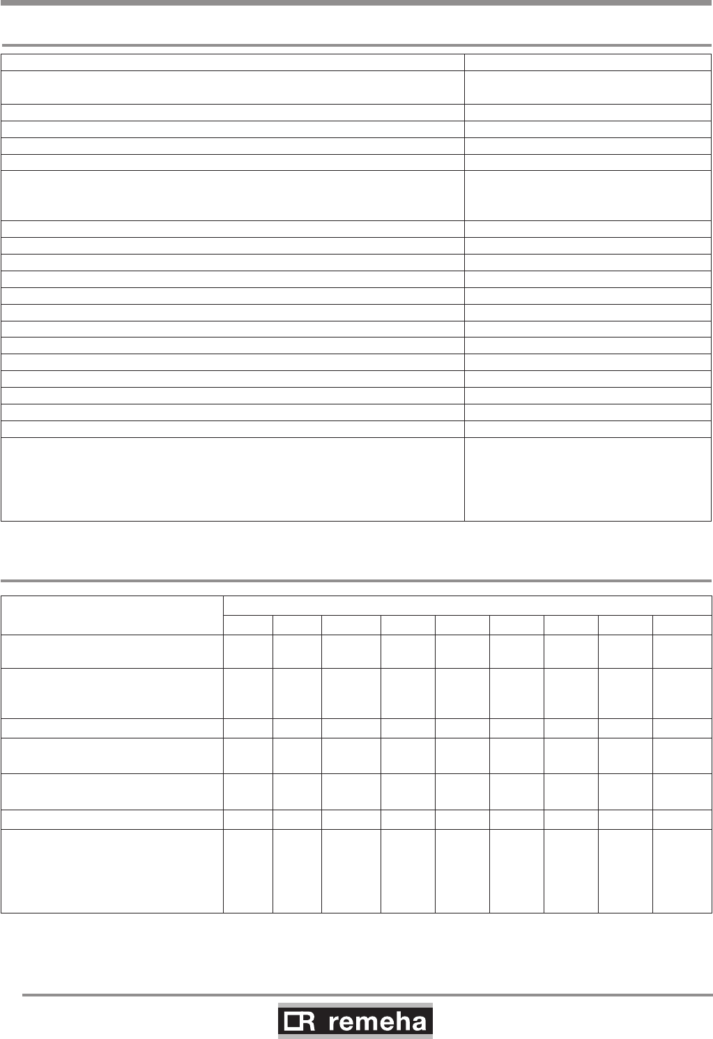
GAS 210 ECO PRO
70
114494-03
17. Checklists (records)
17. Checklists (records)
17.1 Checklist for commissioning (Commissioning record)
Commissioning work, see Section 9.2 Measured value or confirmation
1. Fill the central heating system with water. Check the water pressure in the
central heating system. O
2. Fill trap with water. O
3. Vent central heating system O
4. Check circulation pump operation O
5. Check water-side connections for tightness O
6. Check type of gas offered
(Does the type of gas offered correspond to the type of gas
for which the boiler is suited?)
O Natural gas G20/G25/propane
Wobbe index …….kWh/m3
7. Check the gas supply pressure O
8. Check gas meter capacity O
9. Check the gas tightness of the connections and the gas pipes O
10. Vent gas supply pipe O
11. Check electrical connections O
12. Air supply and flue gas discharge connections checked O
13. Check function and operational status of the boiler O
14. Check whether the gas/air ratio control is correct O
15. Measuring equipment removed and cap refitted on flue gas measuring point O
16. Refit boiler front housing again in the proper manner O
17. Write type of gas on the boiler type plate O
18. Set room thermostat or boiler control to desired value O
19. Instruct user and hand over the necessary documents O
20. Confirmation of commissioning
(Company name, signature of engineer)
Date:
table 20 Commissioning record
17.2 Checklist for annual inspection (inspection record)
Inspection work, see Chapter 10. Confirmation and date
1. Water pressure checked
2. Air supply and
flue gas discharge connections
checked
3. Ignition electrode checked
4. Combustion checked
5. Heat exchanger (central heating)
checked
6. Check the venturi for corrosion
7. Confirmation of inspection
(signature of engineer)
table 21 Inspection record
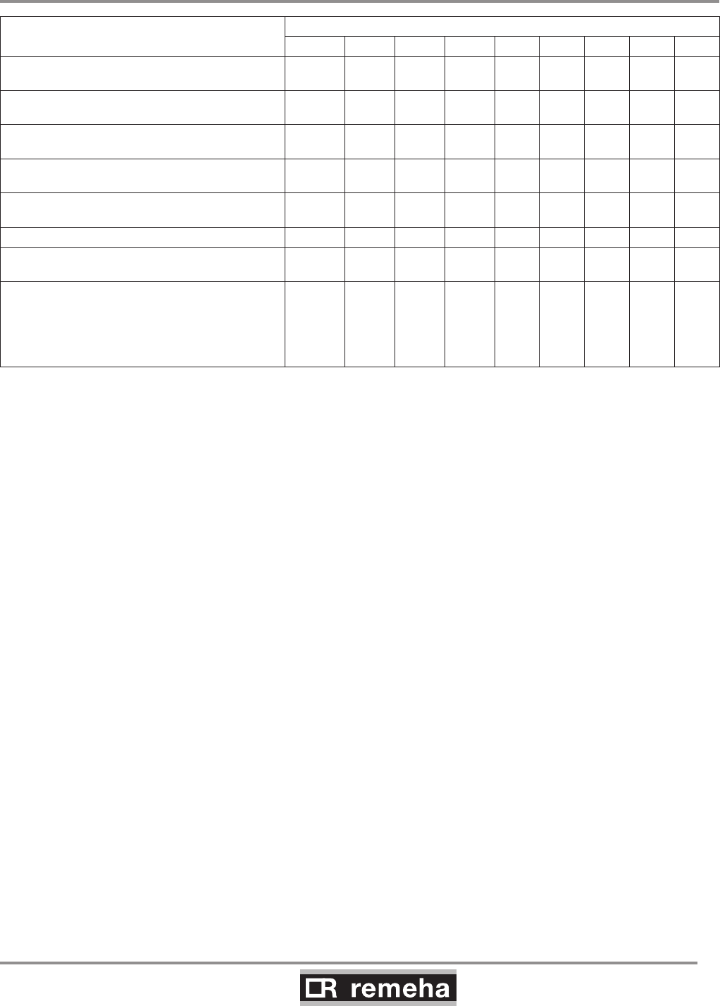
114494-03
GAS 210 ECO PRO
71
17.3 Checklist for maintenance (maintenance record)
Maintenance work
(see Section 10)
Confirmation and date
1. Ignition electrode checked
2. Heat exchanger (central heating) cleaned
3. Combustion checked
4. Water pressure checked
5. Air supply and
flue gas discharge connections checked
6. Check the venturi for corrosion
7. Burner checked
8. Confirmation of maintenance
(signature of engineer)
table 22 Maintenance record
17. Checklists (records)

Remeha Commercial
Innovation House
3 Oaklands Business Centre
Oaklands Park
Wokingham
RG41 2FD
Tel: +44 118 9783434
Fax: +44 118 9786977
Internet: www.remeha.co.uk
E-mail: boilers@remeha.co.uk
04112014
© Copyright
All technical and technological information contained in these technical instructions,
as well as any drawings and technical descriptions furnisched by us remain our
property and may not be multiplied without our prior consent in writing.
114494
