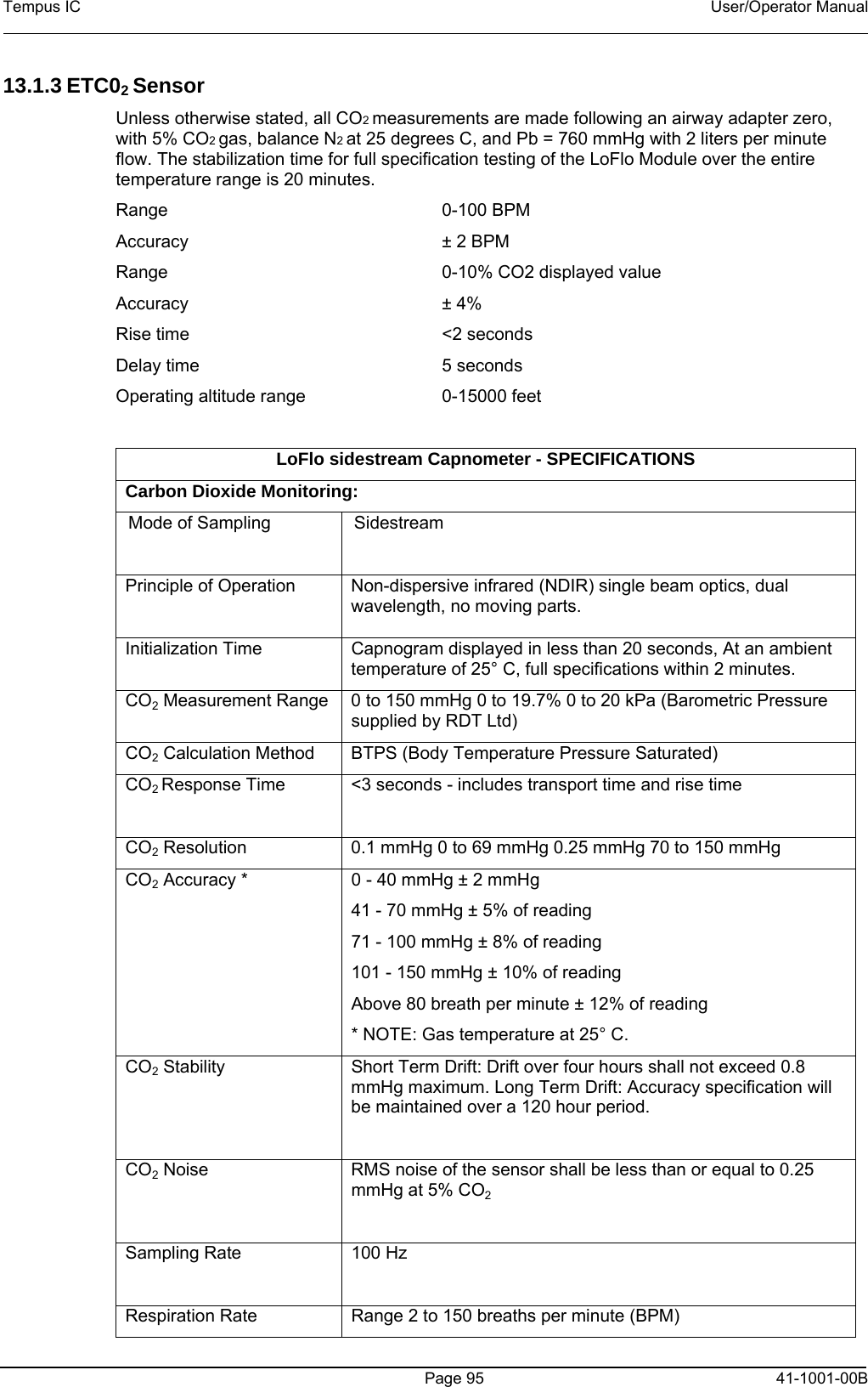
Remote Diagnostic Technologies TEMPUSIC Tempus IC Patient Monitor User Manual Tempus 2000
Remote Diagnostic Technologies Ltd. Tempus IC Patient Monitor Tempus 2000
UserManual.wiki
>
Remote Diagnostic Technologies
>
TEMPUSIC User Manual
User Operator manual
Navigation menu
Upload a User Manual
Namespaces
Wiki Guide
HTML
PDF
Info
Views
User Manual
Discussion / Help
Navigation
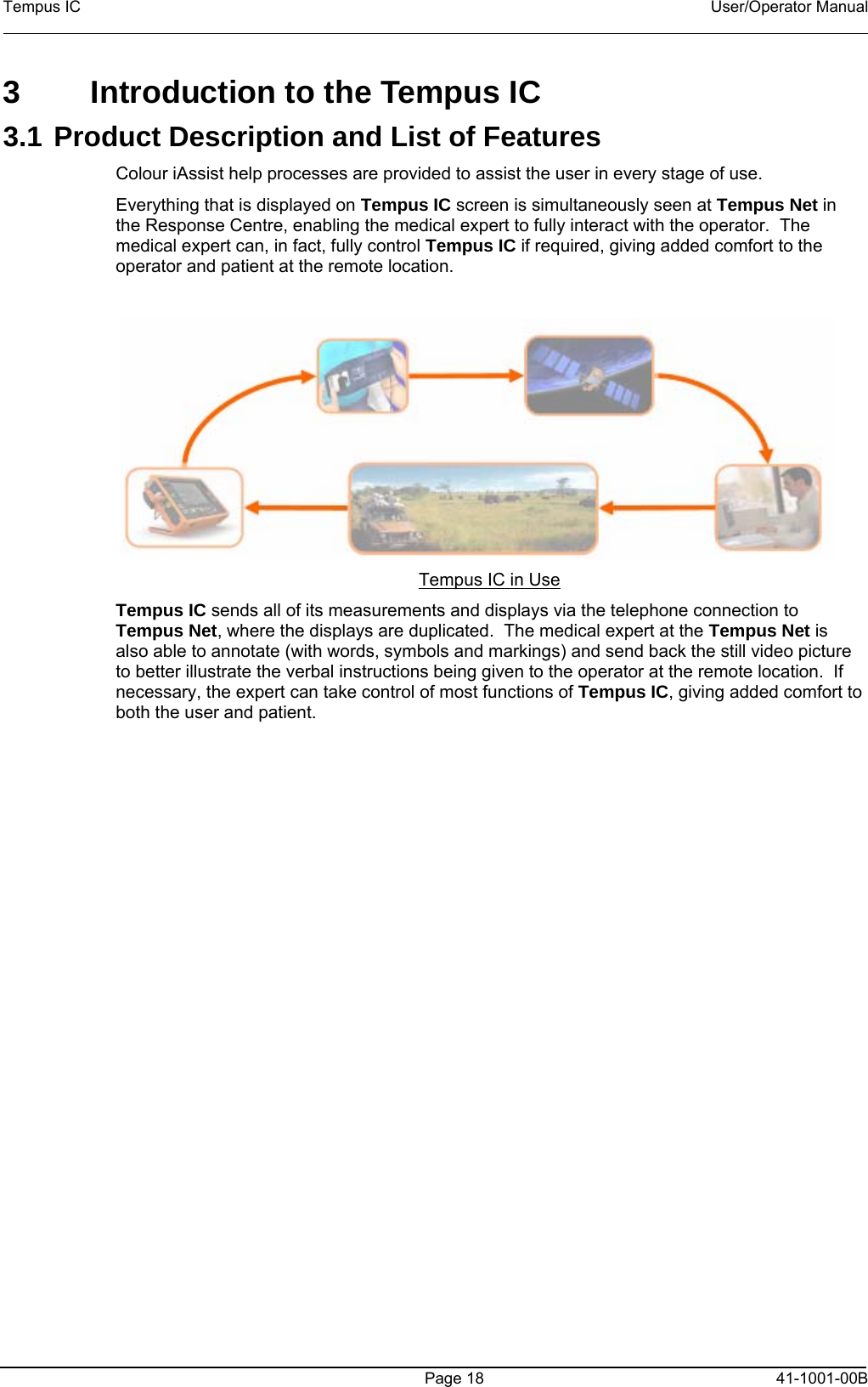
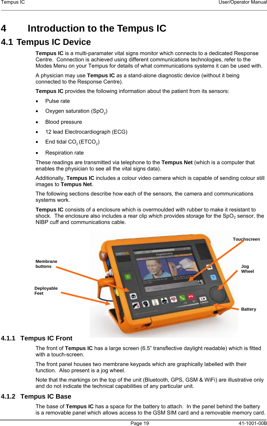
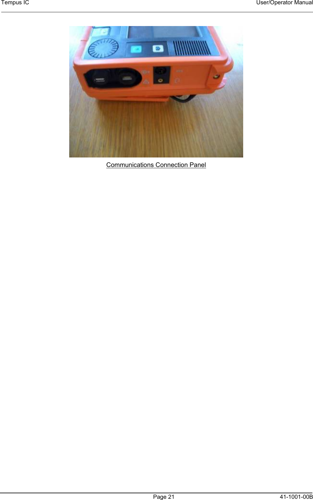

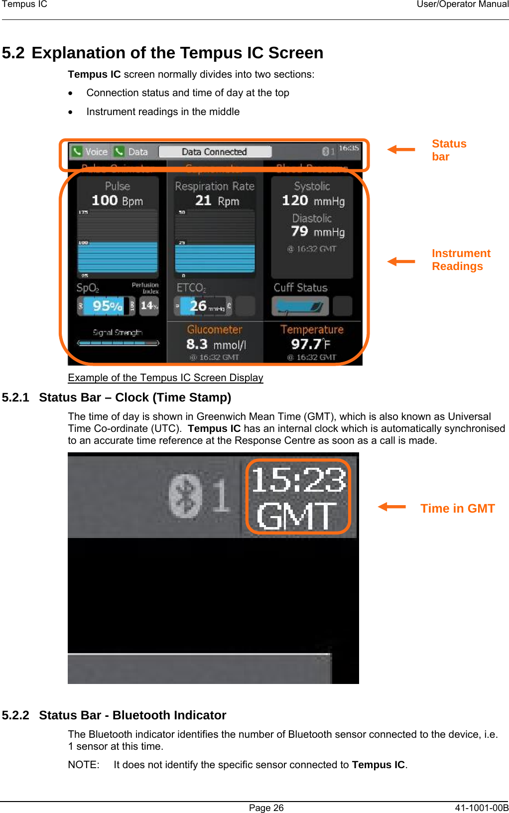
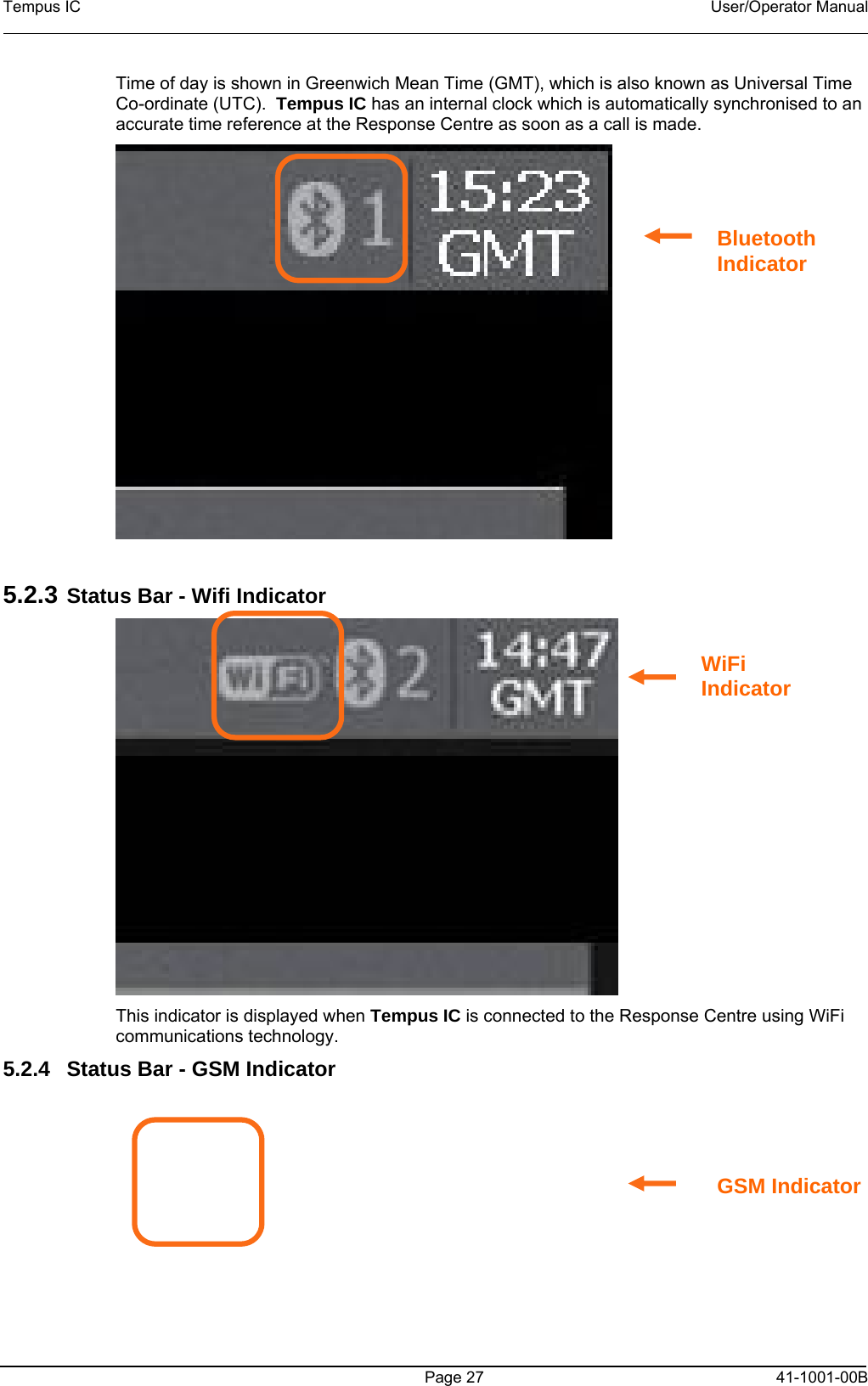
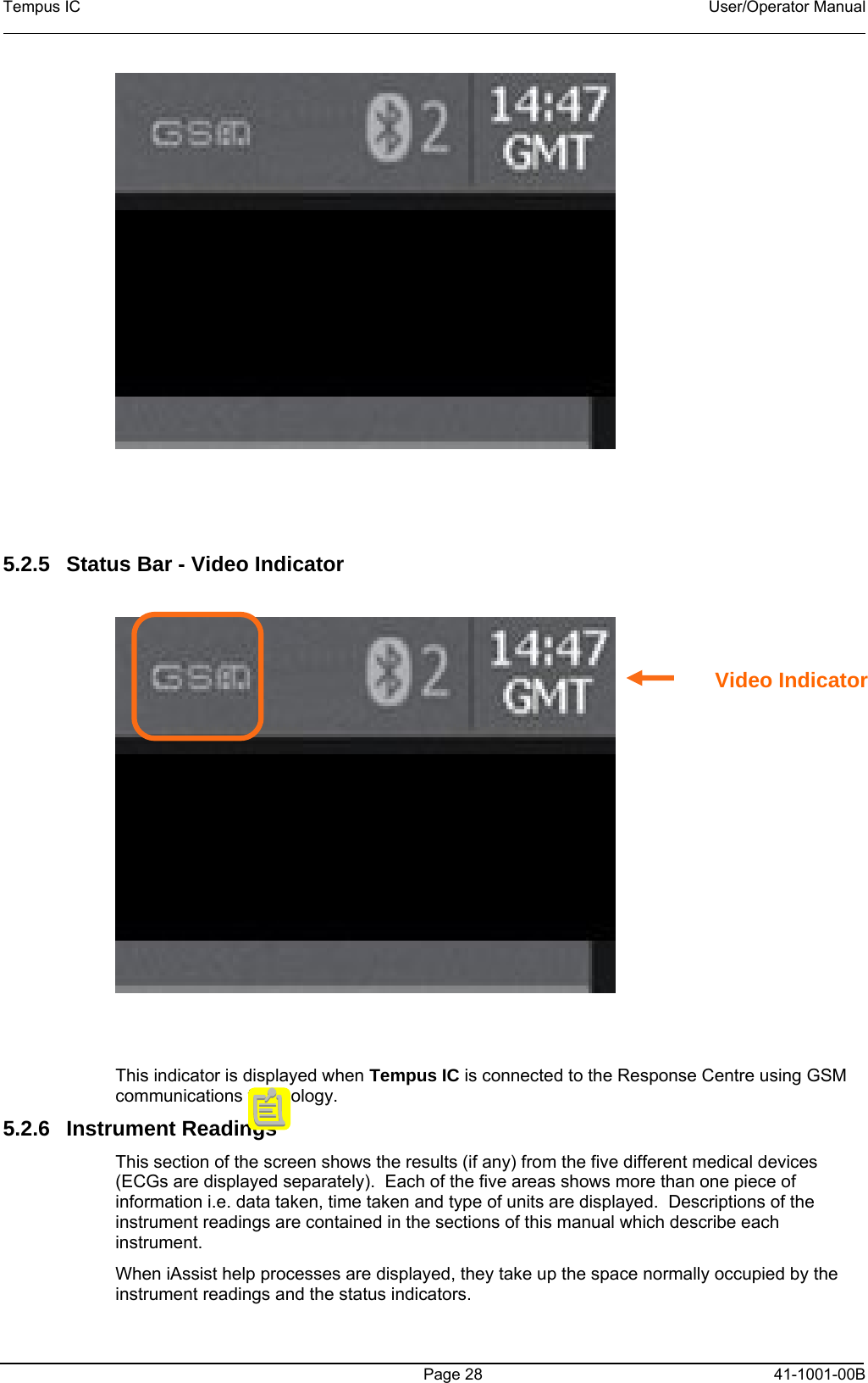
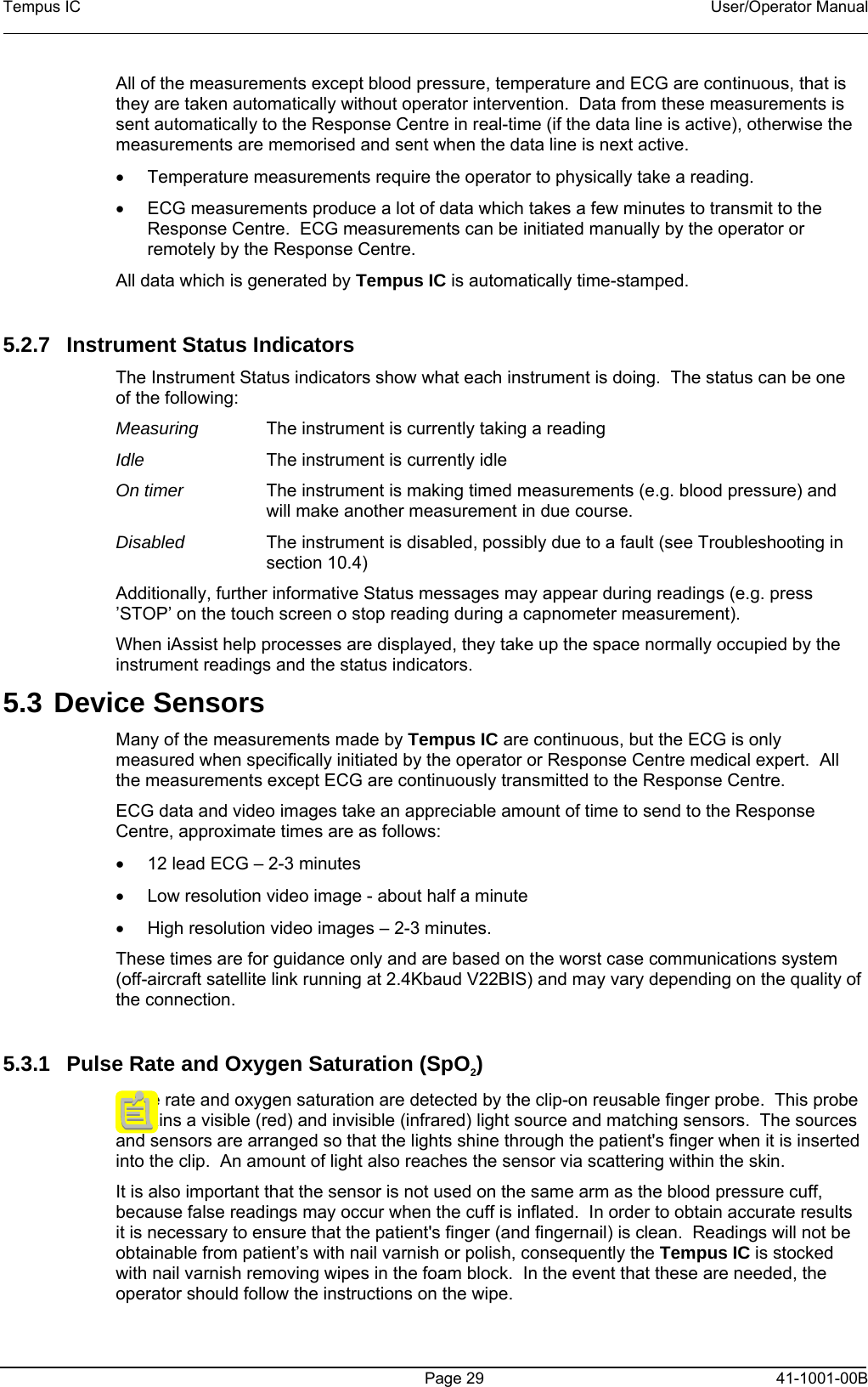
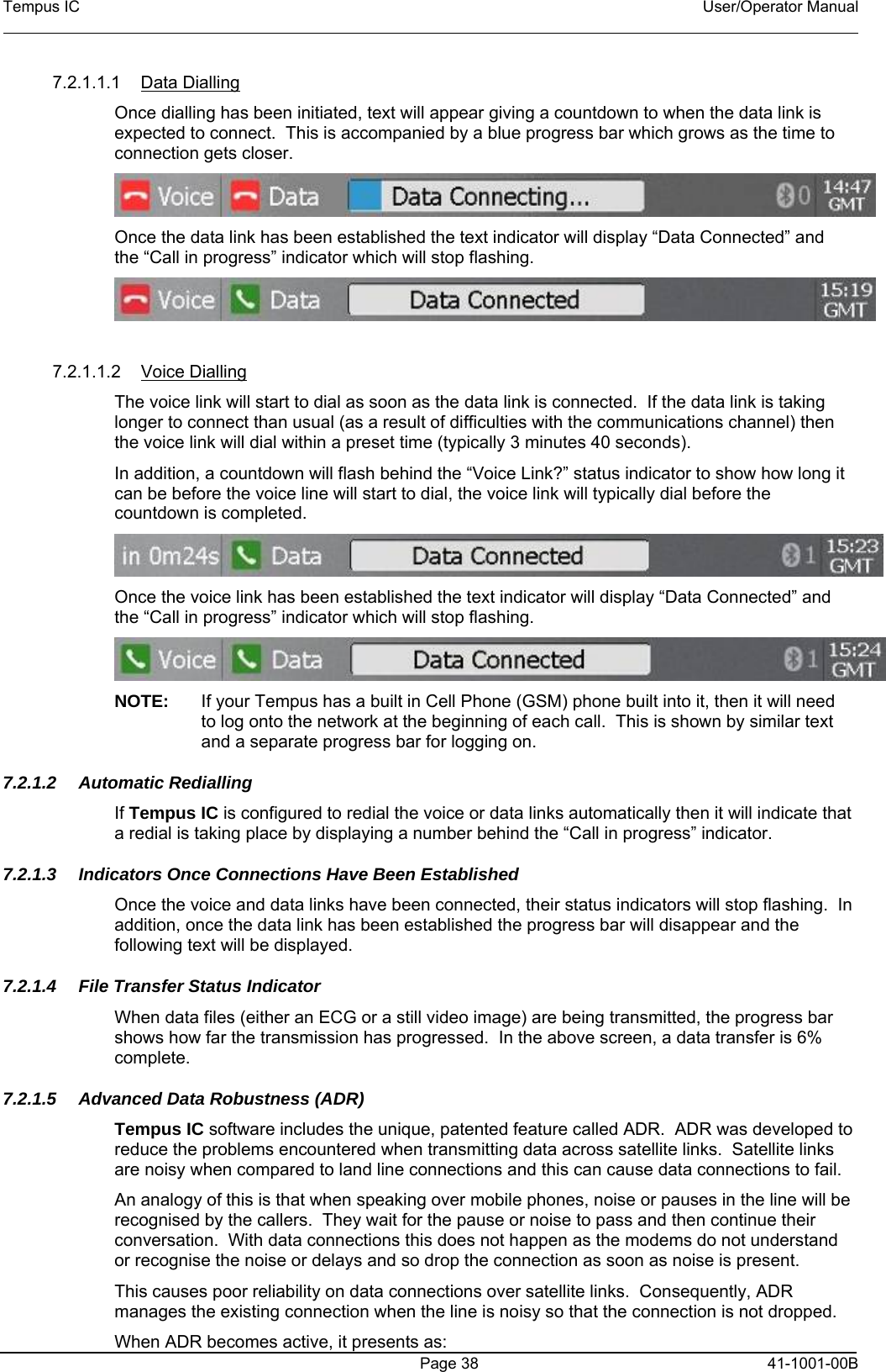
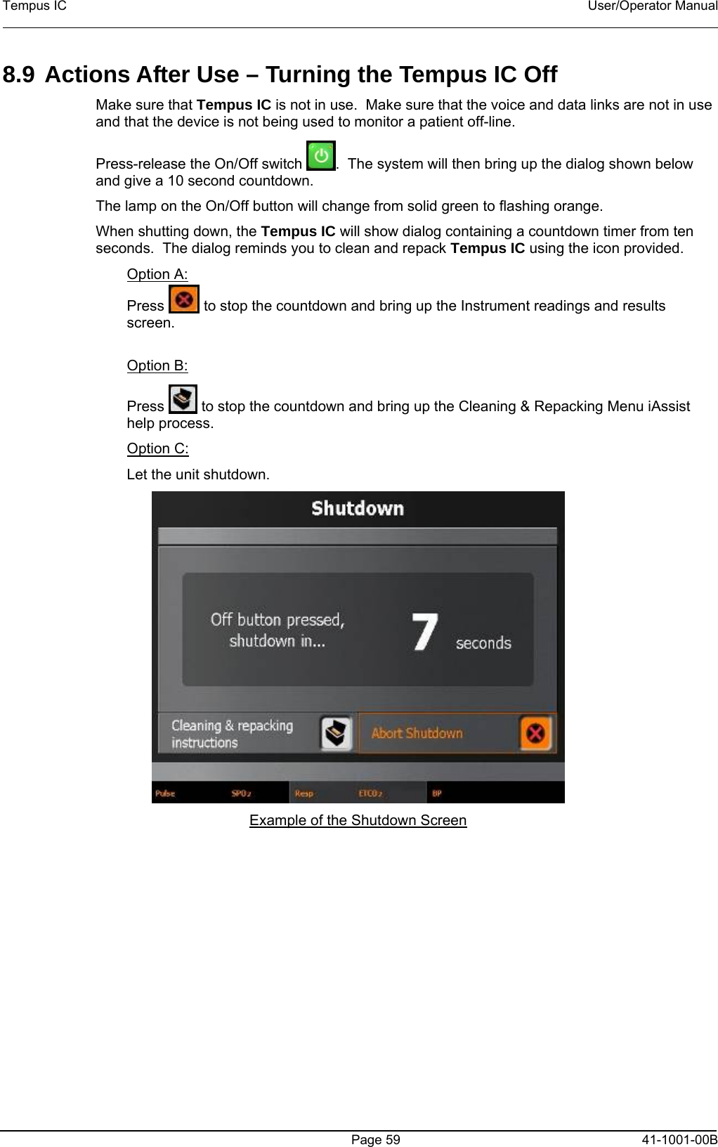
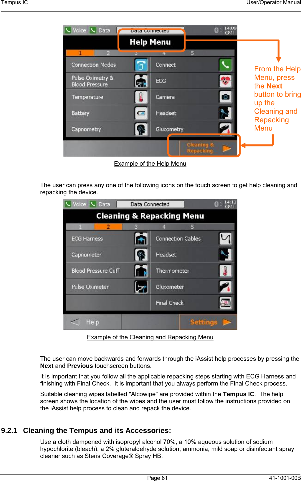

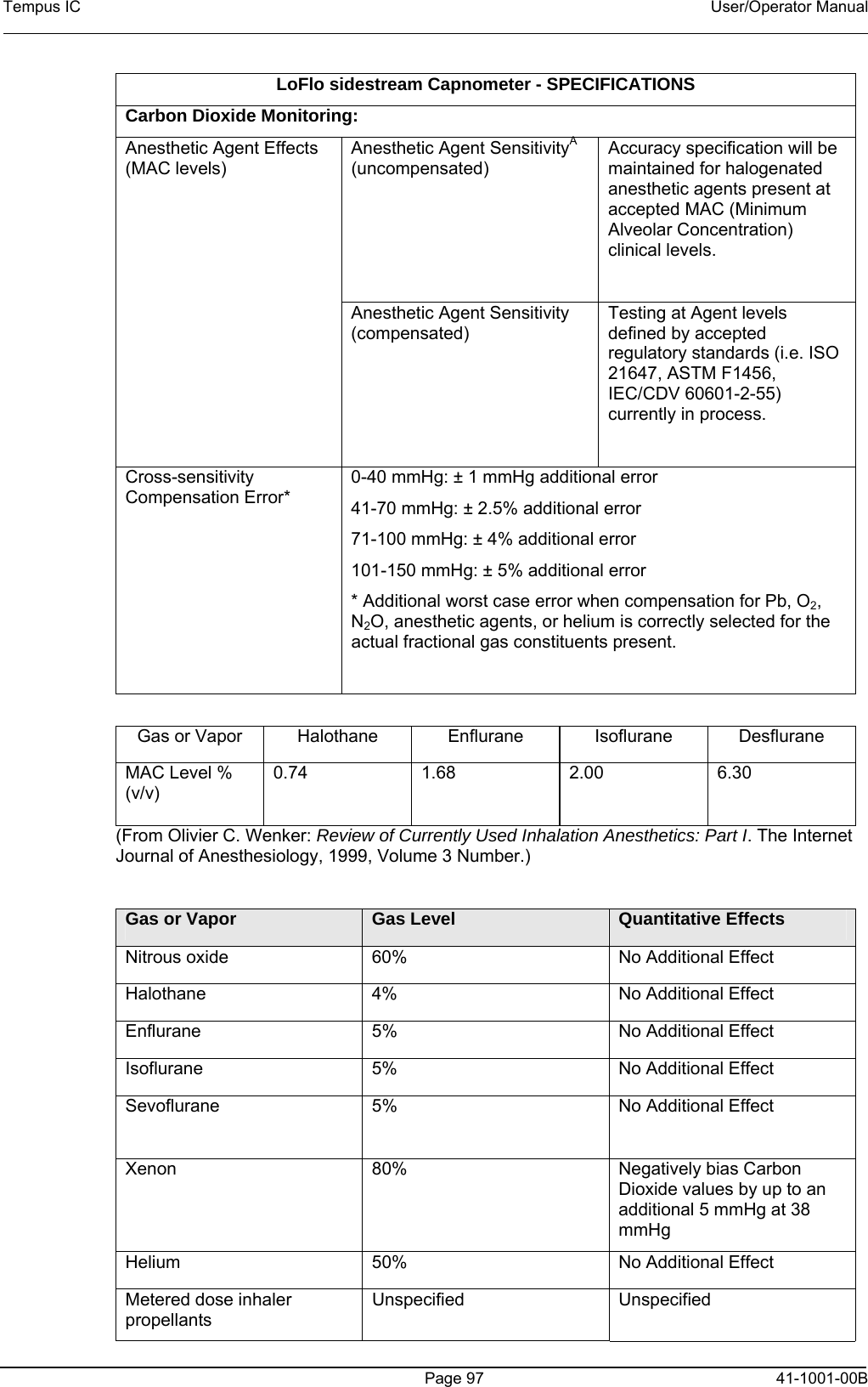
![Tempus IC User/Operator Manual Page 98 41-1001-00B Desflurane 15% Concentrations greater than 5% will positively bias Carbon Dioxide values by up to an additional 3 mmHg at 38 mmHg. Ethanol 0. 1% No Additional Effect Isopropanol 0.1% No Additional Effect Acetone 0.1% No Additional Effect Methane 1% No Additional Effect (From ISO 21647, Medical electrical equipment – Particular requirements for the basic safety and essential performance of respiratory gas monitors, Table 105.) LoFlo sidestream Capnometer - SPECIFICATIONS Physical Characteristics and Host Interface: Physical characteristics Module weight is less than 9.6 oz (272.16 g) Module Size: < 2.6" wide x 1.5" high x 3.5" deep [< 66.0 x 38.1 x 88.9 mm] Cable length – 22 inches (55.88 cm) LoFlo Sidestream Capnometer - SPECIFICATIONS Environmental: Temperature and Humidity Operating 0 to 40°C, 10 to 90% RH, non-condensing Storage -40 to 70°C, 10 to 90% RH, non-condensing Atmospheric Pressure Storage 400-800 mmHg Water Resistance IPX4 - Splash-proof - Module only (When Sample Cell is inserted into Sample Cell Receptacle) Shock Impact IEC TR 60721-4-7 Class 7M3 (designed to withstand environments subject to significant vibrations or high shock levels) EN60068-2-27 Shock EN60068-2-64 Random Vibration Mechanical: Mechanical strength Cable Strain Relief, resistance to pull-out: Cable strain (bend) relief system for the sensor enclosure shall withstand a pull of 30 pounds without failure to either the cable or the enclosure. Cable Strain Relief, flexibility: The connector strain relief system shallwithstand 10,000 bend cycles.](https://usermanual.wiki/Remote-Diagnostic-Technologies/TEMPUSIC/User-Guide-983582-Page-99.png)