Remote Diagnostic Technologies TEMPUSIC Tempus IC Patient Monitor User Manual Tempus 2000
Remote Diagnostic Technologies Ltd. Tempus IC Patient Monitor Tempus 2000
User Operator manual
Tempus IC
User/Operator Manual
Part number 41-1001
Copyright © 2008, RDT Ltd. UK
Date of Issue: 10th June 2008

Tempus IC User/Operator Manual
Page I 41-1001-00B
Contents
1 INTRODUCTION................................................................................................................ 4
1.1 Manufacturer's Address.......................................................................................... 4
1.2 CE Statement ......................................................................................................... 4
1.3 FDA Prescription Statement ................................................................................... 4
1.4 Proprietary Notice................................................................................................... 4
1.5 Use of This Manual................................................................................................. 4
1.6 Patent Claims ......................................................................................................... 4
1.7 Limited Warranty .................................................................................................... 5
1.7.1 Service Support and Returns......................................................................................................... 5
2 WARNINGS AND CAUTIONS ........................................................................................... 6
2.1 EMC Statement ...................................................................................................... 6
2.2 Indications for Use.................................................................................................. 6
2.3 Contraindications.................................................................................................... 6
2.4 Warnings, Cautions and Notes............................................................................... 6
2.4.1 Tempus IC Warnings, Cautions and Notes ................................................................................... 7
2.4.2 LoFlo Sidestream Capnometer - Warnings, Cautions, & Notes.................................................. 14
2.4.3 Pulse Oximeter Sensor - Warnings, Cautions, & Notes..............................................................14
2.4.4 ECG Recorder Sensor - Warnings, Cautions, & Notes............................................................... 15
2.4.5 The Blood Pressure Monitor - Warnings, Cautions, & Adverse Reactions ................................. 16
3 INTRODUCTION TO THE TEMPUS IC.............................................................................18
3.1 Product Description and List of Features.............................................................. 18
4 INTRODUCTION TO THE TEMPUS IC.............................................................................19
4.1 Tempus IC Device................................................................................................ 19
4.1.1 Tempus IC Front.......................................................................................................................... 19
4.1.2 Tempus IC Base .......................................................................................................................... 19
4.1.3 Tempus IC Rear .......................................................................................................................... 20
4.1.4 Tempus IC Sides ......................................................................................................................... 20
5 USING THE TEMPUS IC...................................................................................................22
5.1 Controlling the Tempus IC.................................................................................... 22
5.2 Explanation of the Tempus IC Screen.................................................................. 26
5.2.1 Status Bar – Clock (Time Stamp) ................................................................................................ 26
5.2.2 Status Bar - Bluetooth Indicator................................................................................................... 26
5.2.3 Status Bar - Wifi Indicator............................................................................................................ 27
5.2.4 Status Bar - GSM Indicator.......................................................................................................... 27
5.2.5 Status Bar - Video Indicator......................................................................................................... 28
5.2.6 Instrument Readings.................................................................................................................... 28
5.2.7 Instrument Status Indicators........................................................................................................ 29
5.3 Device Sensors .................................................................................................... 29
5.3.1 Pulse Rate and Oxygen Saturation (SpO2)................................................................................. 29
5.3.2 Blood Pressure ............................................................................................................................ 30
5.3.3 Electrocardiograph (ECG) ........................................................................................................... 30
5.3.4 End Tidal CO2 (ETCO2) and Respiration Rate........................................................................... 30
5.4 Video Camera ...................................................................................................... 30
5.5 Voice and Data Communications ......................................................................... 30

Tempus IC User/Operator Manual
Page II 41-1001-00B
6 SETTING UP.....................................................................................................................32
6.1 Setting up ............................................................................................................. 32
6.1.1 Unpacking the Tempus IC ........................................................................................................... 32
6.2 Tempus IC Bag .................................................................................................... 32
6.2.1 Ensure that Tempus IC is Packed Properly with Sufficient Consumable Items.......................... 33
6.3 Switching On ........................................................................................................ 34
6.3.1 Immediately after Switching On................................................................................................... 34
7 ESTABLISHING COMMUNICATION WITH THE RESPONSE CENTRE.........................35
7.1.1 Process for Connecting the Tempus IC....................................................................................... 35
7.2 Connection Status Indicators................................................................................ 37
7.3 Communications Modes ....................................................................................... 39
8 TAKING MEDICAL READINGS........................................................................................43
8.1 Blood Pressure and Pulse Oximeter..................................................................... 43
8.1.1 Understanding the Pulse Oximeter Results................................................................................. 45
8.1.2 Understanding the Blood Pressure Results................................................................................. 45
8.1.3 Blood Pressure Monitor Error iAssist help process ..................................................................... 46
8.2 Electrocardiograph (ECG) .................................................................................... 46
8.3 The first ECG help screen will appear. ................................................................. 46
8.4 Follow the instructions provided on the iAssist help process to activate ECG...... 46
8.4.1 Monitoring an ECG ...................................................................................................................... 48
8.4.2 Recording an ECG....................................................................................................................... 49
8.4.3 ECG Configuration....................................................................................................................... 50
8.5 Capnometer.......................................................................................................... 52
8.5.1 Understanding the Capnometer Results .....................................................................................53
8.6 Video Camera ...................................................................................................... 54
8.6.1 Annotation of Video Images......................................................................................................... 56
8.7 Interacting with the Response Centre................................................................... 56
8.8 Recording Data Off-line and Transmitting On-line................................................ 57
8.9 Actions After Use – Turning the Tempus IC Off ................................................... 59
9 AFTER USING THE TEMPUS IC......................................................................................60
9.1 Cleaning the Tempus IC....................................................................................... 60
9.2 Cleaning and Re-packing Help Screen................................................................. 60
9.2.1 Cleaning the Tempus and its Accessories: .................................................................................61
9.3 Single-use Devices............................................................................................... 62
10 MAINTENANCE, SERVICING AND TROUBLESHOOTING ............................................63
10.1 General................................................................................................................. 63
10.2 Battery Management ............................................................................................ 63
10.2.1 The Battery.............................................................................................................................. 63
10.2.2 Connecting the Battery............................................................................................................ 64
10.2.3 Charging the Battery ............................................................................................................... 64
10.2.4 Understanding the Battery Life Indicator................................................................................. 65
10.2.5 The Tempus IC Battery ...........................................................................................................65
10.2.6 Checking the Charge State of the Battery............................................................................... 66
10.2.7 Removing the Battery from the Tempus IC............................................................................. 67
10.2.8 Charging the Battery ............................................................................................................... 68
10.2.9 Tempus IC Battery Shelf Life ..................................................................................................70
10.3 Other Tempus IC Batteries................................................................................... 70
10.3.1 Wireless Headset Battery........................................................................................................70
10.3.2 Disposal of Batteries ............................................................................................................... 71

Tempus IC User/Operator Manual
Page III 41-1001-00B
10.4 Troubleshooting.................................................................................................... 71
10.5 Audio & Dialog Errors ........................................................................................... 71
10.5.1 Error Dialog - Type 1............................................................................................................... 71
10.5.2 Error Dialog - Type 2............................................................................................................... 74
10.5.3 Error Dialog - Type 3a............................................................................................................. 76
10.5.4 Error Dialog - Type 3b............................................................................................................. 77
10.5.5 Process Errors......................................................................................................................... 78
10.5.6 Mode Specific Error Processes............................................................................................... 83
10.5.7 Error Dialog - Type 2............................................................................................................... 84
10.5.8 Error Dialog - Type 3a............................................................................................................. 85
10.5.9 Error Dialog - Type 3b............................................................................................................. 86
10.5.10 Error Processes (Graphical Errors)......................................................................................... 87
10.5.11 Mode Specific Error Processes............................................................................................... 88
10.5.12 Shutdown Error Processes...................................................................................................... 90
11 SPARES LIST...................................................................................................................91
11.1 Spares List of the Tempus IC ............................................................................... 91
12 THERMOMETER UNITS, SCREEN BRIGHTNESS & AUDIBLE ALERTS
CONFIGURATIONS.................................................................................................................92
13 SPECIFICATIONS AND STANDARDS ............................................................................94
13.1 Specifications ....................................................................................................... 94
13.1.1 Non-invasive Blood Pressure.................................................................................................. 94
13.1.2 ECG Recorder......................................................................................................................... 94
13.1.3 ETC02 Sensor..........................................................................................................................95
13.1.4 Sp02 Sensor............................................................................................................................. 99
13.1.5 Environmental Specifications .................................................................................................. 99
13.1.6 Miscellaneous Features and Specifications .......................................................................... 100
13.1.7 Communications.................................................................................................................... 100
13.1.8 Classification ......................................................................................................................... 104
13.1.9 Standards Compliance.......................................................................................................... 104
13.1.10 Other Standards Being Used for Reference Purposes ......................................................... 105
13.1.11 Cable Length of the Sensors and the Accessories ............................................................... 106
13.1.12 Manufacturer's Declaration - Electromagnetic Emissions (Tab. 201 according to DIN EN
60601-1-2) .............................................................................................................................................. 106
13.1.13 Manufacturer's Declaration - Electromagnetic Emissions (Tab. 202 according to DIN EN
60601-1-2) .............................................................................................................................................. 106
13.1.14 Manufacturer's Declaration - Electromagnetic Interference Resistance (Tab. 204 according to
DIN EN 60601-1-2)................................................................................................................................. 107
13.1.15 Recommended Safety Distances between portable and mobile RF Telecommunication
Devices and the TEMPUS IC (Tab. 206 according to DIN EN 60601-1-2)............................................ 108
14 SYMBOLS USED ON THE TEMPUS IC.........................................................................110
15 SOFTWARE LICENSE AGREEMENTS .........................................................................113

Tempus IC User/Operator Manual
1 Introduction
1.1 Manufacturer's Address
The Tempus IC is designed and manufactured by:
RDT Limited
The Old Coach House
The Avenue
Farleigh Wallop
Basingstoke
Hampshire
RG25 2HT
UK
Tel +44 (0) 1256 362 400
Fax +44 (0) 1256 362 415
Email sales@rdtltd.com
www.rdtltd.com
1.2 CE Statement
Marking by the symbol indicates compliance of this device to the Medical Devices
Directive 93/42/EEC and the Radio and Telecom Terminal Equipment Directive 1995/5/EC.
The CE mark is accompanied by the number 0473 which is the reference number for the
Notified Body who certify RDT’s quality system.
A Declaration of Conformity in accordance with the above regulations has been made and is on
file at Remote Diagnostic Technologies Ltd at the address in section 1.1.
1.3 FDA Prescription Statement
Federal law (USA) restricts the use or sale of this device by, or on the order of, a physician.
1.4 Proprietary Notice
Information contained in this document is copyright © 2008 by Remote Diagnostic
Technologies Limited ('RDT') and may not be reproduced in full or in part by any means or in
any form by any person without prior written permission from RDT.
The purpose of this document is to provide the user with adequately detailed information to
efficiently install, operate, maintain and order spare parts for the Tempus IC. Every effort has
been made to keep the information contained in this document current and accurate as of the
date of publication or revision. However, no guarantee is given or implied that the document is
error free or that it is accurate with regard to any specification. Tempus ICTM is a registered
trademark of RDT Ltd.
1.5 Use of This Manual
The instructions and safety precautions provided in this manual must be observed during all
phases of the operation, usage, service or repair of the Tempus or its accessories. Failure to
comply with the information contained in this manual e.g. warnings, precaution, instructions etc.
will violate the safety standards of design, manufacture and intended use of the product. RDT
Ltd assumes no liability for customer failure to comply with the information contained in this
manual.
Users of Tempus IC and its accessories are advised to convey the following safety information
to operating personnel and to incorporate applicable information into their own internal
literature where necessary.
1.6 Patent Claims
RDT has applied for patents covering Tempus IC and its communications technology in the
following jurisdictions:
Patents Pending (US No.2006/0287586 EP 1734458 A & other areas).
Page 4 41-1001-00B

Tempus IC User/Operator Manual
Page 5 41-1001-00B
1.7 Limited Warranty
Remote Diagnostic Technologies Limited ('RDT') warrants each new Tempus IC to be free
from defects in workmanship and materials under normal conditions of use and service. For
details please refer to the Terms and Conditions of Sale. Consumable items are expressly
excluded from this Warranty. RDT's sole obligation under this warranty will be to repair or (at
RDT's option) replace products that prove to be defective during the warranty period. The
foregoing shall be the sole warranty remedy. Except as set forth herein, RDT makes no
warranties, either expressed or implied, including the implied warranties of merchantability and
fitness for a particular purpose. The warranty shall be void if Tempus IC is in any way modified
or if it is used with non-approved consumables, unless specifically authorised in writing by RDT,
and RDT shall not be liable in any event for incidental or consequential damage. This warranty
is not assignable.
Full terms and conditions of sale are available from RDT and are provided with your order
confirmation.
1.7.1 Service Support and Returns
Repairs made under warranty to Tempus IC must be made by the manufacturer. If Tempus IC
requires repair or return for any reason, please contact your local distributor or Remote
Diagnostic Technologies at the address in section 1.1 in order to first obtain a returns reference
(RMA) number. RDT reserves the right not to accept returns which have not first been
provided with an RMA number. When calling, please be ready to quote the serial number of
Tempus IC.
The Tempus IC is designed to be as maintenance free as possible. The only user replaceable
and user serviceable parts in the Tempus IC are those listed in section 10 of this manual.
In the event that the device fails to operate correctly or in a way that is not described in this
manual, stop using the device immediately and switch the device off immediately. Contact the
manufacturer or distributor at once. Do not attempt any kind of corrective action and do not
connect the device to a patient.

Tempus IC User/Operator Manual
Page 6 41-1001-00B
2 Warnings and Cautions
2.1 EMC Statement
Tempus IC remote patient monitor has been tested and approved to IEC/EN60601-1-2:2007.
This means that Tempus IC meets or exceeds the requirements for electrical medical
equipment in terms of its levels of emitted electromagnetic radiation and its susceptibility to
electromagnetic radiation from other devices.
In addition, Tempus IC has been tested according to the requirements of RTCA DO160-E
section 21 category M.
It should be noted that Tempus IC may be affected by high levels of stray EM radiation from
other electronic devices (even those which comply with relevant CISPR emission standards)
that are being used in close proximity to it.
As required by international medical device standards, Tempus IC is intended for use in
electromagnetic environments of ±6kV static contact (±8kV air discharge) and magnetic fields
of 3A/m (50/60Hz). Tempus IC is proof against radiated RF emissions from 80MHz to 2.5GHz
to a level of 3V/m. In the event that Tempus IC will be used in environments with RF levels
exceeding this, please contact RDT for further information.
2.2 Indications for Use
Tempus IC is intended to aid with the diagnosis of a person presenting as unwell or sick when
they are in a location remote from immediate medical assistance. The device allows the User
to take vital signs data from a patient and to transmit that data to medical professionals located
at the response centre elsewhere. Typical examples are remote land, sea or air locations.
Tempus IC is intended primarily to be used by medically unqualified people who have received
basic training in the use of the device. Medical expertise is provided through communication
with the Response Centre which would be staffed by physicians who would advise the operator
on the nature of the medical incident.
Tempus IC is intended to be used where a physician or other medically trained staff may or
may not be present but where remote physician support is required.
A trained medical professional such as a physician or paramedic may also use Tempus IC.
Tempus IC is suitable for use on adults or children (over 10 years old and over 20kg in weight).
2.3 Contraindications
Tempus IC is not intended to be used on extremely small or extremely large patients; this limit
is set by the physical limits of the ECG harness.
Tempus IC does not replace a physician’s care. The device is not intended for neonatal use.
The device is not an apnoea monitor.
Tempus IC is not intended to be used in strong magnetic or electro-magnetic fields which are
generated for medical purposes e.g. MRI. The Tempus is not for use with electro-cautery
devices.
Tempus IC is not intended to allow a lay user to make any clinical decision for treatment or
diagnosis.
Tempus IC ECG is not intended to be used on patients with prosthetic limbs.
2.4 Warnings, Cautions and Notes
KEYWORD DEFINITION
WARNING Indicates a potentially harmful condition that can lead to personal injury.
CAUTION Indicates a condition that may lead to equipment damage or malfunction.
NOTE A point of particular interest or emphasis intended to provide more effective or convenient.

Tempus IC User/Operator Manual
Page 7 41-1001-00B
2.4.1 Tempus IC Warnings, Cautions and Notes
WARNING
It is essential to switch off the Tempus IC between applying it to
different patients in order to ensure patient records remain
separate.
WARNING: Federal law (USA) restricts the use or sale of this device by, or on the order
of, a physician.
WARNING: The Tempus IC is not intended for unsupervised patient monitoring. There
are no audible or visible alarms.
WARNING: Do not use device in the presence of flammable anaesthetics or fuels.
WARNING: Do not autoclave, ethylene oxide sterilise, or immerse in liquid or immersing
the sensors in liquid as it may cause sensor damage which may result in
inaccurate readings.
WARNING: ELECTRICAL SHOCK HAZARD when covers are removed. Do not remove
covers. Refer servicing to qualified personnel authorised by RDT.
WARNING: Device must be used in conjunction with clinical signs and symptoms. Device
is only intended to be an adjunct in patient assessment.
WARNING: The sensors of the Tempus IC are only for contact with intact and
undamaged skin.
WARNING: Any device or accessory that has been dropped, damaged or subjected to
harsh or extreme environmental conditions should be inspected by qualified
service personnel prior to use to ensure proper operation.
WARNING: The Tempus IC is not for use on neonates.
WARNING: The device should not be used on patients undergoing defibrillation. The
Tempus IC is protected against defibrillator discharge but rate meters and
displays may be temporarily affected during defibrillator discharge but will
rapidly recover.
WARNING: There is no defibrillator synchronisation output on the device. Make no
connections between the device and a defibrillator.
WARNING: Device will not operate effectively on patients who are experiencing
convulsions or tremors.
WARNING: Device is not for apnoea detection. Device has not been tested or validated
for use in apnoea detection.
WARNING: Misuse or improper handling of the device or its sensors or cables can cause
damage which may lead to equipment failure or inaccurate readings.
WARNING: Misuse or improper handling of the device (its sensors or cables) can cause
damage which may lead to equipment failure or inaccurate readings.
WARNING: Do not attempt to charge a non-rechargeable battery. Never charge, crush,
heat or incinerate, short-circuit, deform, puncture, dismantle or immerse the
batteries in any liquid. Remove batteries when discharged.
WARNING: Only use rechargable batteries and battery chargers specified by RDT.
WARNING: Ensure patient cabling or tubing is carefully routed on device to reduce the
possibility of patient entanglement or strangulation

Tempus IC User/Operator Manual
Page 8 41-1001-00B
WARNING: Verify normal operation if utilizing device adjacent to or stacked with other
electrical equipment.
WARNING: All numerical, graphical and interpretive data should be evaluated with
respect to the patient's clinical and historical picture
WARNING: Do not attempt to insert any connections from the Tempus IC (including
patient cables) directly into an electrical outlet
WARNING: Attention should be paid to the following EMC information prior to installing
or using the device.
WARNING: Portable and mobile Radio Frequency (RF) communication equipment may
interfere with the operation of the device.
WARNING: Device has been tested and found to comply with IEC/EN 60601-1-2.
WARNING: Computers, cables and accessories not tested to IEC/EN60601-1-2 or
equivalent IEC standards may result in increased emissions or decreased
immunity of device.
WARNING: Explosion Hazard: DO NOT use the Tempus IC in the presence of
flammable anesthetics or other flammable gasses. Use of the Tempus IC in
such environment may present an explosion hazard.
WARNING: Electrical Shock Hazard: Always disconnect the LoFlo sidestream
Capnometer before cleaning. Do NOT use if it appears to have been
damaged. Refer servicing to qualified service personnel.
WARNING: Follow precautions for electrostatic discharge (ESD) and electromagnetic
interference (EMI) to and from other equipment.
WARNING: Failure of Operation: If the Tempus IC fails to respond as described in this
user guide; DO NOT use it until approved for use by qualified personnel.
WARNING: Reuse, disassembly, cleaning, disinfecting or sterilizing of any single use
items (such as the Capnometer cannula) may compromise functionality and
system performance leading to a user or patient hazard. Performance is not
guaranteed if an item labelled as single patient use is reused.
WARNING: Do not apply excessive tension to any cable.
WARNING: Electrical Shock Hazard; No user serviceable parts inside
WARNING: Before use, carefully read the Operator’s Guide and these operating
instructions.
WARNING: Using a damaged patient sensor may cause inaccurate readings, possibly
resulting in patient injury or death. Inspect each sensor. If a sensor
appears damaged, do not use it. Use another sensor or contact your
authorized repair center for help.
WARNING: Using a damaged patient cable may cause inaccurate readings, possibly
resulting in injury or death. Inspect the patient cable. If the patient cable
appears damaged, do not use it. Contact your authorized repair center for
help.
WARNING: Do not use Tempus IC stacked with or adjacent to other equipment.
WARNING: Only use Tempus IC with the relevant cables and peripherals provided by RDT.
WARNING: Only connect Tempus IC to IT and communications systems which are
compliant with the relevant IEC standard e.g. IEC60950.
WARNING: Exposure of the wireless communication features of the Tempus IC
may be interfered with by other devices which operate at the same
frequencies.
CAUTION: Do not disassemble the device. There are no user-serviceable parts inside.
Refer servicing to the manufacturer. Changes or modifications not
expressly approved by RDT could void the user’s authority to operate the
equipment.

Tempus IC User/Operator Manual
Page 9 41-1001-00B
CAUTION: Repairs or service activity not detailed in this manual or in accompanying
documents must only be undertaken by personnel trained or authorized by
RDT.
CAUTION: Autoclaving, ethylene oxide sterilizing, or immersing the sensors in liquid
may cause sensor damage which may result in inaccurate readings.
CAUTION: This device is intended for use by persons trained in professional health
care. The operator must be thoroughly familiar with the information in this
manual before using the device.
CAUTION: The Tempus IC may not operate correctly if used or stored outside the
relevant temperature or humidity ranges described in the performance
specifications of this manual.
CAUTION: Only use only approved accessories supplied by RDT.
CAUTION: DO NOT clean the IC or its accessories except as directed in this guide.
CAUTION: DO NOT apply excessive tension to any of the Tempus IC cables.
CAUTION: Read all instructions for use and specifications provided prior to use.
CAUTION: Device is intended for use by persons trained in its operation. The operator
must be thoroughly familiar with the information in this manual before using
the device.
CAUTION: The device is not intended to, and does not, sound alarms for physiological
parameters.
CAUTION: In the event that the device displays an error that is not described within this
manual e.g. Windows applications errors, turn the device off and then on
again. This should clear the error and allow normal operation to resume.
Do not continue to use the device if such an error is displayed. If symptoms
persist, please contact RDT.
CAUTION: Device must be switched off between taking readings from different
patients.
CAUTION: Should the device become wet, wipe off all moisture and allow sufficient
time for drying before operating. Take care to ensure that water or liquids
are not spilt over the device or into its ventilation holes in the side corners.
CAUTION: If the accuracy of any measurement is in question, verify the patient's vital
sign(s) by an alternative method and then check the monitor for proper
functioning.
CAUTION: Follow local government regulations and recycling instructions regarding
disposal and recycling of device and device components.
CAUTION: The Tempus IC and its accessories uses both rechargeable and non-
rechargeable batteries. If any battery fails to hold a charge or otherwise
becomes inoperable, the battery should be replaced and the old battery
should be disposed of properly. RDT cannot dispose of used batteries.
Dispose of batteries in accordance with applicable regulations which vary
from country to country.
(In most countries, the trashing of used batteries is forbidden and the end-
users are invited to dispose them properly, eventually through not-for-profit
profit organisations, mandated by local governments or organised on a
voluntary basis by professionals).
CAUTION: Pressing buttons and touch screen with sharp or pointed instruments may
permanently damage the buttons and touch screen. Only fingers should be
used to press these keys.
CAUTION: Do not reconnect the headset to its docking pin when the main battery is
very low or flat (less than 10% charge – as represented by a single flashing
red LED on the battery charge indicator). Doing this could reduce the
battery charge into a “deep discharge” state (where no battery lights come
on).

Tempus IC User/Operator Manual
CAUTION: Only connect the device to communications systems which are compliant
with relevant international safety standards e.g. IEC60950 for IT and
telecommunications equipment. Only connect the device to
communications systems which it is intended to be used with.
CAUTION: Do not touch electrically live parts of other electrical systems while touching
the patient.
CAUTION: Use of monitoring during continuous nebulised medication delivery will
result in damage to the device which is not covered by the warranty.
Disconnect the capnometer sample line from the device, or switch off the
device, during medication delivery.
CAUTION: Observe proper battery polarity (direction) when replacing batteries. The
batteries slide easily into place when correctly oriented and should not be
forced.
CAUTION: The mobile RF communications equipment contained within the device and
its accessories can affect other medical devices that are in close proximity
to the device.
CAUTION: Use of the RF communications equipment contained in the device and its
accessories may be prohibited in a number of areas. These include: on
aircraft in-flight (including during take-off and landing), near defibrillators
(that are in use), near other electronic medical devices and in hospitals.
CAUTION: In addition, the use of the RF communications equipment contained in the
device and its accessories may be prohibited in explosive atmospheres e.g.
in fuelling areas, near fuel or chemical transfer or storage areas and in
areas containing chemicals or particles such as grain, dust or metal
powders.
CAUTION: Do not transport or store the device with flammable gas, liquids or
explosives.
CAUTION: The use of the RF communications equipment contained in the device and
its accessories may cause interference with some implanted pacemakers
and other medically implanted equipment.
A minimum distance of 2.3m (7.5 feet) must be maintained between the
device and its accessories (containing RF communications equipment) and
other medical equipment (including implantable medical devices such as
defibrillators and pacemakers). Note that if such medical equipment has an
electromagnetic interference immunity level of less than 3V/m (or 10V/m for
implantable devices), this distance should be increased in line with the
requirements of IEC60601-1-2:2007.
If the intended patient has an implantable device (e.g. implantable
pacemaker), do not use any of the Tempus IC’s RF communications
equipment (e.g. Bluetooth or WiFi) before using the device to record the
patient's physiological data. After the data recording session is completed,
move the device at least 2.3 CCm away from the patient, and then use it
normally to communicate with the base station. Otherwise, radiofrequency
radiation from the device (up to 63mW) may adversely impact the
implantable pacemaker in the patient. If the patient's implantable device
has an immunity level less than 10 V/m, the separation has to be greater
than 2.3 m
If you suspect interference is being caused, disconnect the
connection to the response centre by pressing . Examples of
interference could include visible interference on equipment displays,
audible interference e.g. buzzing, from speakers of other equipment, or
equipment unexpectedly changing state e.g. functions starting or stopping.
Examples of visible interference on a PC display are shown below:
Example of a PC display with no interference
Page 10 41-1001-00B
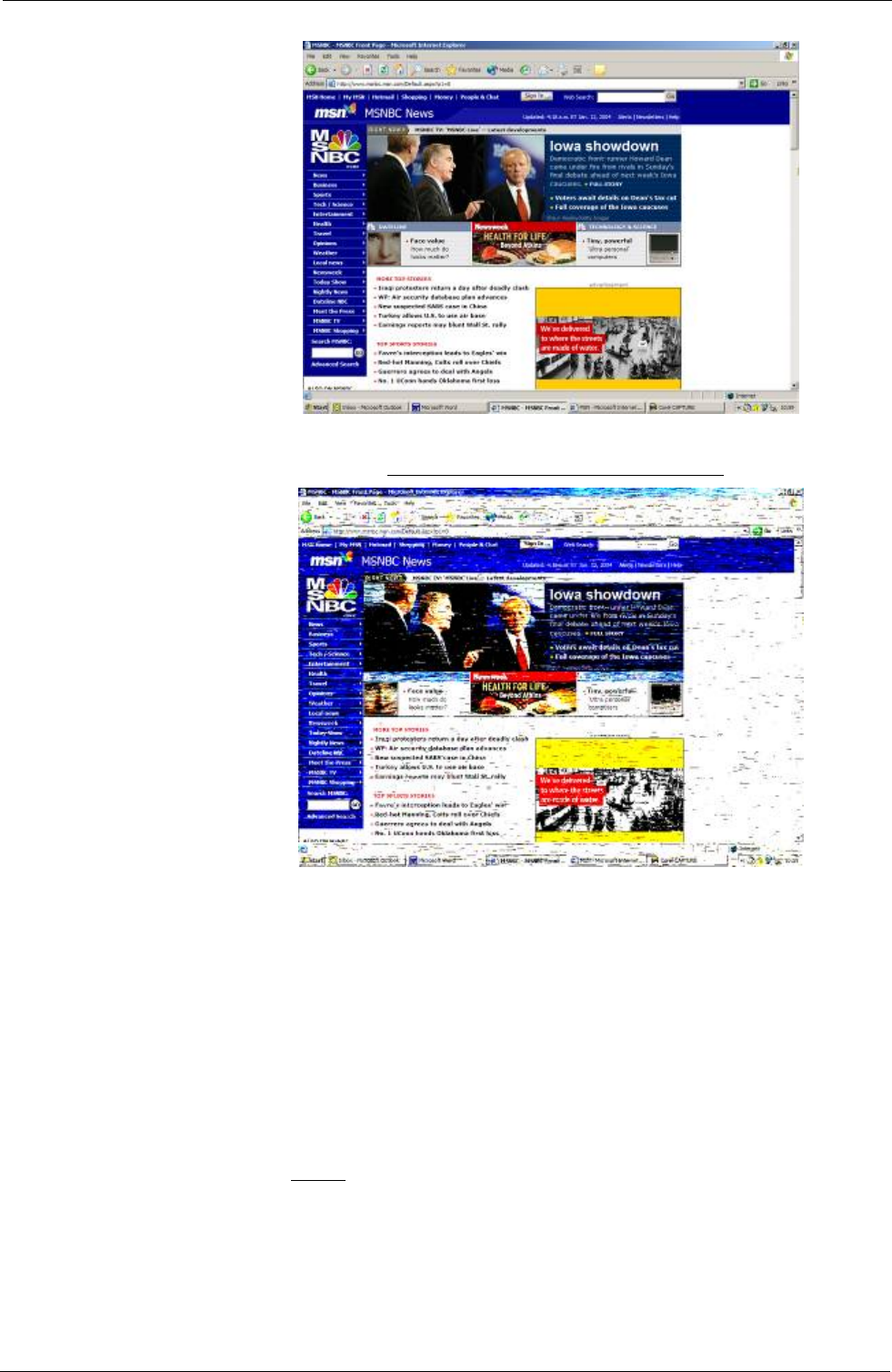
Tempus IC User/Operator Manual
Example of a PC display with interference
A minimum distance of 20cm (8”) must be maintained between the device
and the body of the User or Patient.
CAUTION: When using the device with portable satellite terminals such as Iridium
handsets or GAN terminals, ALWAYS ensure that the terminal is provided
with any applicable data adaptors and is set up to support data calls. It is
recommends that Users thoroughly familiarise themselves with the operation
their satellite terminals and perform a test connection BEFORE going into the
field with the equipment. Advice on this can be sought from RDT if required.
CAUTION: When using the device with GAN terminals, in order to avoid the risk of
interference from the output beam from the antenna of the terminal with the
operation of the device, ALWAYS ensure that the device is situated at least
6m behind the face of the antenna. Since the power of the GAN terminal’s
beam is high (25W apx), care should be taken to ensure that the antenna
remains fixed and to maintain the device away from the face (and therefore
the beam) of the antenna.
CAUTION: Do not reconnect the headset to its docking pin when the main battery is very
low or flat (less than 10% charge – as represented by a single flashing red
LED on the battery charge indicator). Doing this could reduce the battery
charge into a “deep discharge” state (where no battery lights come on).
Page 11 41-1001-00B

Tempus IC User/Operator Manual
Page 12 41-1001-00B
CAUTION: RF energy may affect some electronic systems in motor vehicles, such as car
stereo, safety equipment, etc. Check with your vehicle manufacturer’s
representative to be sure that your product will not affect the electronic
system in your vehicle.
CAUTION: Do not use the Tempus IC’s Bluetooth or WiFi communications on-board any
aircraft where its use is prohibited.
CAUTION: Do not use the Tempus IC during take-off or landing
NOTE: If all the battery lights remain off when the battery button is pressed, the
battery may be in a “deep discharge” state. The battery is not damaged when
in this state but will require an extended period on a charger (additional 2-3
hours) in order to restore normal operation.
NOTE: Important! The Tempus IC is intended for use in the electromagnetic
environment(s) specified in this manual. Users of this equipment should
ensure that it is used in such environment(s).
NOTE: The Tempus IC or its accessories contain no user serviceable parts except as
detailed by this manual or accompanying documents. Refer service to
qualified service personnel.
NOTE: This product and its accessories are latex free.
NOTE: After the life cycle of the Tempus IC and its accessories have been met,
disposal should be accomplished following national and/or local
requirements.
NOTE: Operation of the device may be adversely affected in the presence of
conducted electrical transients or strong electromagnetic or radio frequency
sources such as electrosurgery and electrocautery equipment, HF radio
transmission antenna, x-ray machines and high intensity infrared radiation.
NOTE: All user and patient accessible materials are non-toxic.
NOTE: Hazards arising from software errors have been minimised. Hazard analysis
was performed to meet the requirements of EN14971 and IEC60601-1-4.
NOTE: Each external connection and part of the device is electrically isolated.
NOTE: Performance and safety test data are available on request from the address
in section 1.1.
NOTE: Device complies with Part 68 of the US FCC Rules and the requirements
adopted by ACTA . The device is labelled with, among other information, a
product identifier in the format US:AAAEQ###TXXXX. If requested, this
number must be provided to the telephone company.
NOTE: A plug and jack used to connect the device to the premises wiring and
telephone network must comply with the applicable FCC Part 68 rules and
requirements adopted by ACTA. A compliant telephone cord and modular
plug is provided with this product. It is designed to be connected to a
compatible modular jack that is also compliant.
NOTE: The REN is used to determine the number of devices that may be connected
to a telephone line. Excessive RENs on a telephone line may result in the
devices not ringing in response to an incoming call. In most but not all areas,
the sum of RENs should not exceed five (5.0). To be certain of the number of
devices that may be connected to a line, as determined by the total RENs,
contact the local telephone company. For products approved after July 23,
2001, the REN for this product is part of the product identifier that has the
format US:AAAEQ##TXXXX. The digits represented by ## are the REN
without a decimal point (e.g., 03 is a REN of 0.3). For earlier products, the
REN is separately shown on the label.
NOTE: If the device causes harm to the telephone network, the telephone company
will notify you in advance that temporary discontinuance of service may be
required. But if advance notice isn't practical, the telephone company will
notify the customer as soon as possible. Also, you will be advised of your
right to file a complaint with the FCC if you believe it is necessary.

Tempus IC User/Operator Manual
NOTE: The telephone company may make changes in its facilities, equipment,
operations or procedures that could affect the operation of the equipment. If
this happens the telephone company will provide advance notice in order for
you to make necessary modifications to maintain uninterrupted service.
NOTE: If the equipment is causing harm to the telephone network, the telephone
company may request that you disconnect the equipment until the problem is
resolved.
NOTE: Connection to party line service is subject to state tariffs. Contact the state
public utility commission, public service commission or corporation
commission for information.
NOTE: If your home or area of installation has specially wired alarm equipment
connected to the telephone line, ensure the installation of the device does not
disable your alarm equipment. If you have questions about what will disable
alarm equipment, consult the supplier as described in section 1.7.1.
NOTE: This equipment is not hearing aid compatible.
NOTE: ALWAYS ensure that any satellite terminals e.g. GAN or Mini-M terminals,
used with the device are powered from mains power supplies which are
earthed. Using a non-earthed power supply with satellite terminals will cause
interference on the ECG trace. Earthed power supplies will always have a
three pin connector to plug the mains lead into, non-earthed power supplies
will always have the following symbol on their label . In addition, when
purchasing any replacement power supplies for satellite terminals, always
ensure that the replacement has the same input and output voltage (V),
current (A) and power (W) ratings, the same type and polarity of output
connector and is approved to EN/IEC60950 (safety standard). Advice on this
matter may be sought from RDT if needed.
NOTE: GSM usage is restricted by the network availability, roaming agreements and
local provision of circuit mode connections.
NOTE: Users who own multiple device units should note that their device are likely to
be pre-configured for different aircraft, yachts or other locations according to
the customer’s needs. Consequently different device units owned by one
User may not necessarily be compatible with all of the customer’s different
aircraft, yachts etc. Users should refer to RDT’s delivery notes which will
detail if specific device is configured for specific applications. Alternatively
please check with a technical contact at RDT for confirmation.
NOTE: Users should not put the device into service until they have been trained in its
use and also (where appropriate) the device has been commissioned on their
aircraft, vessel or other intended site of operation.
NOTE: IP sealing is not guaranteed if the device is subject to rough handling, impact,
improper use, rapid decompression
NOTE: Device should be returned for service if it is subject to rough handling and IP
sealing is needed to be relied upon.
NOTE: The Tempus IC’s water ingress seals are warranted for 1 year from the date
of manufacture.
NOTE: The device specifications are subject to change without notice.
NOTE: It is recommended that the device is connected to the response centre every
month for a test patch.
NOTE: The iAssist help processes on your Tempus IC may differ from the example
iAssist help process used in this manual; however the process always follows
the same key elements.
NOTE: Always ensure that you read the complete iAssist help process in order and
do exactly what it requires.
Page 13 41-1001-00B

Tempus IC User/Operator Manual
Page 14 41-1001-00B
NOTE: For optimum performance of the wireless communications, please make sure
that there is no metal surrounding the Tempus IC.
NOTE: Overbending the folding foot or RapdiPak clip could cause them to be
damaged. Do not over-bend these items.
NOTE: Take care when repacking cables to ensure they cannot be snagged or
damaged in the RapidPak clip and the folding foot.
NOTE: The Tempus IC should be repacked following the relevant instructions. Lost
or damaged cables and accessories should be replaced with spares ordered
from RDT.
2.4.2 LoFlo Sidestream Capnometer - Warnings, Cautions, & Notes
WARNING: Do not operate the LoFlo sidestream Capnometer if it fails to operate
properly, if it appears to have been damaged or when it is wet or has
exterior condensation.
WARNING: DO NOT use device on patients that can not tolerate the withdrawal of 50
ml/min +/- 10 ml/min from the airway or patients that can not tolerate the
added dead space to the airway.
WARNING: Do not connect the exhaust tube to a ventilator circuit.
CAUTION: DO NOT sterilize or immerse the LoFlo sidestream Capnometer in liquids.
CAUTION: DO NOT store the LoFlo sidestream Capnometer at temperatures less than
-40º F (-40º C) or greater than 158º F (70º C).
CAUTION: DO NOT operate the LoFlo sidestream Capnometer at temperatures less
than 32º F (0º C) or greater than 104º F (40º C).
CAUTION: Remove the LoFlo sampling kit sample cell from the receptacle when not in
use.
CAUTION: DO NOT stick appendage into sample receptacle.
NOTE: Recommended operating temperature is 32º F (0º C) to 104º F (40º C).
NOTE: Nitrous oxide, elevated levels of oxygen, helium , Xenon, halogenated
hydrocarbons, and barometric pressure can influence the CO2
measurement..
2.4.3 Pulse Oximeter Sensor - Warnings, Cautions, & Notes
WARNING: Do not use this device in the presence of high EMI/RFI radiation. High
EMI/RFI radiation may cause induced current to the SpO2 sensor resulting
in patient injury.
WARNING: This device may give inaccurate readings in the presence of strong
electromagnetic sources, such as electrosurgery equipment.
WARNING: This device may give inaccurate readings in the presence of computed
tomography (CT) equipment.
WARNING: This device must be used in conjunction with clinical signs and symptoms.
This device is only intended to be an adjunct in patient assessment.
WARNING: Prolonged use or the patient’s condition may require changing the sensor
site periodically. Change sensor site and check skin integrity, circulatory
status, and correct alignment at least every 4 hours. Prolonged use may
cause blisters, skin deterioration, and discomfort.
WARNING: Incorrectly applied sensors may give inaccurate readings.
WARNING: SpO2 measurements may be inaccurate in the presence of high ambient
light. Shield the sensor area (with a towel, for example) if necessary.
WARNING: Dyes introduced into the bloodstream, such as methylene blue, indocyanine
green, indigo carmine, patent blue V (PBV), and fluorescein may adversely
affect the accuracy of the SpO2 reading.

Tempus IC User/Operator Manual
Page 15 41-1001-00B
WARNING: Any condition that restricts blood flow, such as use of a blood pressure cuff
or extremes in systemic vascular resistance, may cause an inability to
determine accurate pulse rate and SpO2 readings.
WARNING: Remove fingernail polish or false fingernails using the wipe provided before
applying SpO2 sensors. Fingernail polish or false fingernails may cause
inaccurate SpO2 readings.
WARNING: Significant levels of dysfunctional hemoglogins, such as carboxyhemoglogin
or methhemoglobin, will affect the accuracy of the SpO2 measurement.
WARNING: Tissue damage may result from overexposure to sensor light during
photodynamic therapy with agents such as verteporphin, porfimer sodium
and metatetrahydroxyphenylchlorin (mTHPC). Change the sensor site at
least every hour and observe for signs of tissue damage. More frequent
sensor site changes or inspections may be indicated depending upon the
photodynamic agent used, agent dose, skin condition, total exposure time
or other factors. Use multiple sensor sites.
WARNING: Ethylene oxide sterilizing the sensor may lead to tissue damage when the
sterilized sensor is placed on a patient.
WARNING: Optical cross-talk can occur when two or more sensors are placed in close
proximity. It can be eliminated by covering each site with opaque material.
Optical cross-talk may adversely affect the accuracy of the SpO2 readings.
WARNING: Obstructions or dirt on the sensor’s red light or detector may cause a sensor
failure or inaccurate readings. Make sure there are no obstructions and the
sensor is clean.
WARNING: Under certain clinical conditions, pulse oximeters may display dashes if
unable to display SpO2 and/or pulse rate values. Under these conditions,
pulse oximeters may also display erroneous values. These conditions
include, but are not limited to: patient motion, low perfusion, cardiac
arrhythmias, high or low pulse rates or a combination of the above
conditions. Failure of the clinician to recognize the effects of these
conditions on pulse oximeter readings may result in patient injury.
CAUTION: Unplug the sensor from the monitor before cleaning or disinfecting to
prevent damaging sensor or monitor, and to prevent user safety hazards.
NOTE: SpO2 averaging is the number of pulse beats over which the SpO2 value is
averaged; pulse averaging is the number of seconds over which the pulse
value is averaged.
NOTE: DESAT trails were performed in the normal sensitivity mode.
NOTE: Use proper disposal guidelines when discarding the device.
2.4.4 ECG Recorder Sensor - Warnings, Cautions, & Notes
WARNING: The computerized interpretation is only valid when used in conjunction with
clinical findings. All computer generated tracings and interpretations must
be confirmed by a qualified physician. Test interpretations are intended for
the physician's use only. All ECG numerical and graphical data should be
evaluated with respect to the patient's clinical and historical picture.
WARNING: The ECG device is not intended for use in a sterile environment. Do not use
for direct cardiac application.
WARNING: The ECG device is reusable
WARNING: Do not attempt to insert the ECG device (including patient cables) into an
electrical outlet
WARNING: The ECG is for resting recordings and should not be used in stress testing
environments
WARNING: Though false positive errors will intentionally outnumber false negative
errors, both will occur, thus the necessity for over reading by a qualified

Tempus IC User/Operator Manual
Page 16 41-1001-00B
physician of any computer-interpreted ECG. The computer interpretation
does not produce a definitive diagnosis.
WARNING: Ensure electrodes are connected only to the patient
WARNING: Conductive parts of electrodes and connectors, including neutral electrode,
should not contact other conductive parts including earth
WARNING: The Tempus IC is rated as being proof against the effects of a defibrillator
discharge. Follow these warnings if using an AED or defib with the Tempus
IC:
− Follow the instructions of the defibrillator or AED when using it wih the
Tempus IC.
− Do not touch the patient during defibrillation
Do not touch the defibrillator’s paddle-electrode surface when discharging
the defibrillator
− Keep defibrillation electrodes well clear of other electrodes or metal parts
in contact with the patient
− Do not touch the patient, bed, or any conductive material in contact with
the patient during defibrillation
CAUTION: The ECG is designed and tested to AAMI EC11
CAUTION: Electrocardiography – The suggested maximum electrode duration is 8
hours
2.4.5 The Blood Pressure Monitor - Warnings, Cautions, & Adverse Reactions
WARNING: This device should not be used when oscillometric pulses may be altered by
other devices or techniques such as External Counterpulsation (ECP) or
Intra Aortic Balloon Pump Counterpulsation.
WARNING: DO NOT use the Blood pressure monitor for any purpose other than
specified in this manual.
WARNING: DO NOT attach the cuff to a limb being used for IV infusions as the cuff
inflation can block the infusion, potentially causing harm to the patient.
CAUTION: Accuracy of any blood pressure measurement may be affected by the
position of the subject, his or her physical condition and use outside of the
operating instructions detailed in this manual. Interpretation of blood
pressure measurements should be made only by a physician or trained
medical staff.
CAUTION: Hoses of a certain material and/or durometer may cause the module to
perform in an improper fashion.
CAUTION: Incorrectly sized cuffs may cause measurement inaccuracy or errors.
CAUTION: If the blood pressure cuff is on the same limb as a pulse oximeter probe, the
oxygen saturation results will be altered when the cuff occludes the brachial
artery.
CAUTION: To obtain accurate blood pressure readings, the cuff must be the correct
size, and also be correctly fitted to the patient. Incorrect size or incorrect
fitting may result in incorrect readings.
CAUTION: When a cuff is going to be positioned on a patient for an extended length of
time, be sure to occasionally check the limb for proper circulation.
CAUTION: Allergic exanthema (symptomatic eruption) in the area of the cuff may
result, including the formation of urticaria (allergic reaction including raised
edematous patches of skin or mucous membranes and intense itching)
caused by the fabric material of the cuff.
CAUTION: Petechia (a minute reddish or purplish spot containing blood that appears in
the skin) formation or Rumple-Leede phenomenon (multiple petechia) on
the forearm following the application of the cuff, which may lead to

Tempus IC User/Operator Manual
Page 17 41-1001-00B
Idiopathic thrombocytopenia (spontaneous persistent decrease in the
number of platelets associated with hemorrhagic conditions) or phlebitis
(inflammation of a vein) may be observed.
Tempus IC User/Operator Manual
3 Introduction to the Tempus IC
3.1 Product Description and List of Features
Colour iAssist help processes are provided to assist the user in every stage of use.
Everything that is displayed on Tempus IC screen is simultaneously seen at Tempus Net in
the Response Centre, enabling the medical expert to fully interact with the operator. The
medical expert can, in fact, fully control Tempus IC if required, giving added comfort to the
operator and patient at the remote location.
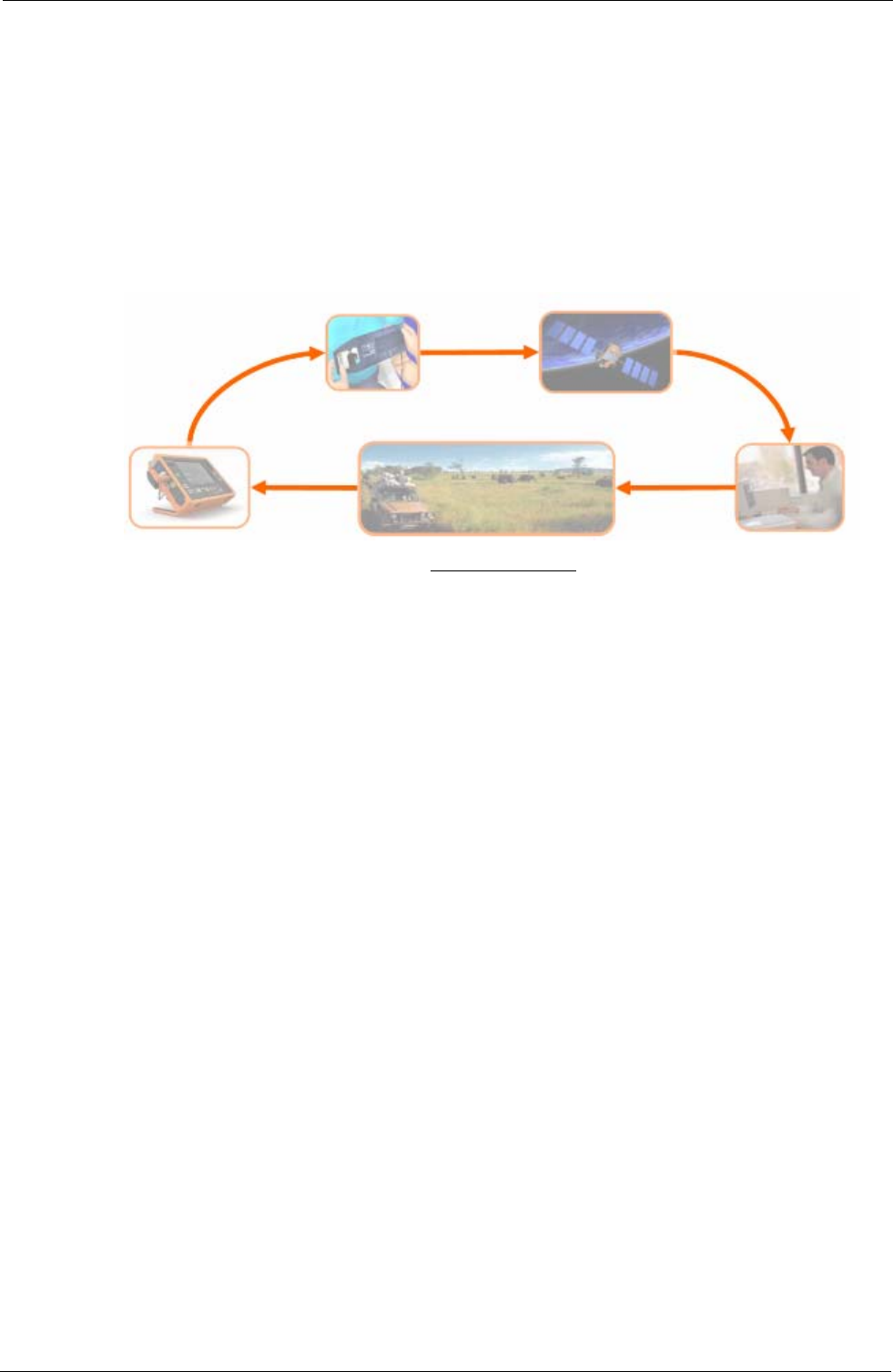
Tempus IC in Use
Tempus IC sends all of its measurements and displays via the telephone connection to
Tempus Net, where the displays are duplicated. The medical expert at the Tempus Net is
also able to annotate (with words, symbols and markings) and send back the still video picture
to better illustrate the verbal instructions being given to the operator at the remote location. If
necessary, the expert can take control of most functions of Tempus IC, giving added comfort to
both the user and patient.
Page 18 41-1001-00B
Tempus IC User/Operator Manual
4 Introduction to the Tempus IC
4.1 Tempus IC Device
Tempus IC is a multi-paramater vital signs monitor which connects to a dedicated Response
Centre. Connection is achieved using different communications technologies, refer to the
Modes Menu on your Tempus for details of what communications systems it can be used with.
A physician may use Tempus IC as a stand-alone diagnostic device (without it being
connected to the Response Centre).
Tempus IC provides the following information about the patient from its sensors:
• Pulse rate
• Oxygen saturation (SpO2)
• Blood pressure
• 12 lead Electrocardiograph (ECG)
• End tidal CO2 (ETCO2)
• Respiration rate
These readings are transmitted via telephone to the Tempus Net (which is a computer that
enables the physician to see all the vital signs data).
Additionally, Tempus IC includes a colour video camera which is capable of sending colour still
images to Tempus Net.
The following sections describe how each of the sensors, the camera and communications
systems work.
Tempus IC consists of a enclosure which is overmoulded with rubber to make it resistant to
shock. The enclosure also includes a rear clip which provides storage for the SpO2 sensor, the
NIBP cuff and communications cable.
The
Page 19 41-1001-00B
Tempus IC
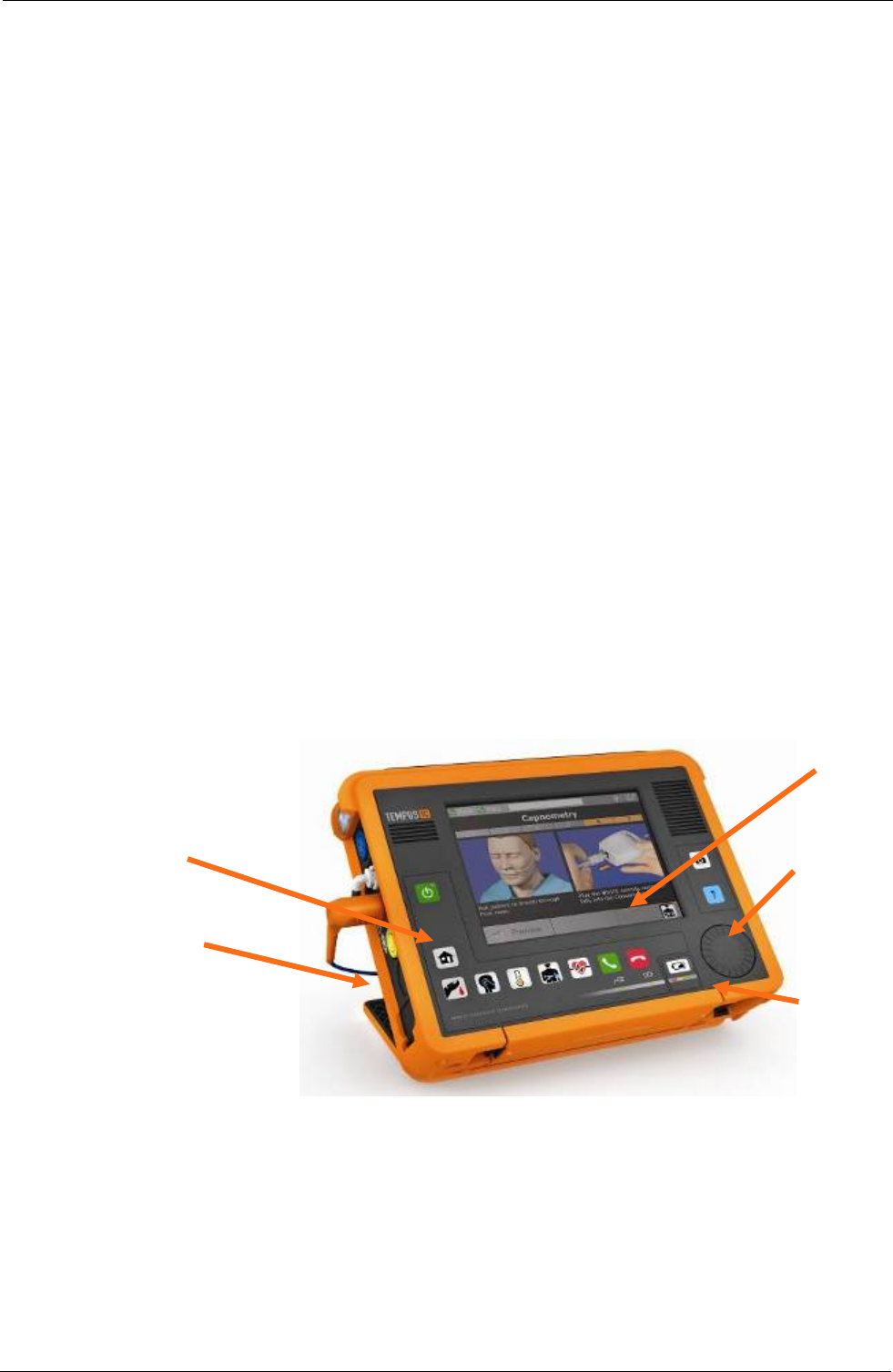
4.1.1 Tempus IC Front
The front of Tempus IC has a large screen (6.5” transflective daylight readable) which is fitted
with a touch-screen.
The front panel houses two membrane keypads which are graphically labelled with their
function. Also present is a jog wheel.
Note that the markings on the top of the unit (Bluetooth, GPS, GSM & WiFi) are illustrative only
and do not indicate the technical capabilities of any particular unit.
Deployable
Feet
Membrane
buttons Jog
Wheel
Touchscreen
Battery
4.1.2 Tempus IC Base
The base of Tempus IC has a space for the battery to attach. In the panel behind the battery
is a removable panel which allows access to the GSM SIM card and a removable memory card.
Tempus IC User/Operator Manual
The base of the device also has a docking connector to allow the unit to be docked to a cradle
in future applications.
4.1.3 Tempus IC Rear
The rear of Tempus IC houses the RapidPakTM clip (discussed above) and the Bluetooth
Headset. This item is docked onto a connector which enables the VSM to top the charge of the
headset up automatically on a regular basis, thus ensuring the headset is always ready to use.
Also on the rear is the aperture for the camera and backlight, this aperture is labelled for
aesthetic purposes. The clip carries a general product label for regulatory purposes and also
two labels which help guide the user to repack the SpO2 sensor and the comms cable. The
top of the clip carries a product-specific brand also.
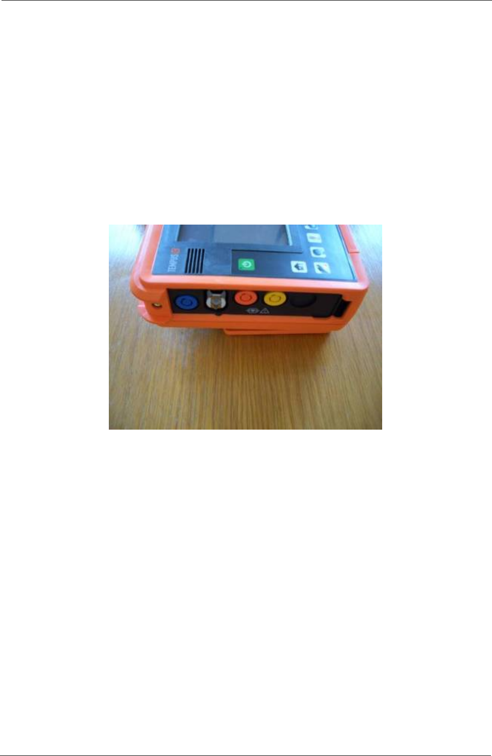
4.1.4 Tempus IC Sides
The left side of the VSM houses the medical connections. These are colour-coded and are
rated IP67. Connections are provided for ECG, NIBP, SpO2 and ETCO2. Normally the NIBP
and SpO2 connectors will have their mating half attached at all times.
The right side of the VSM houses the non-medical connections. These comprise:
USB – this is reserved for non-mains powered USB peripherals (such as mouse and
keyboards) to be specified by RDT
RJ-45 Ethernet – use only the Ethernet cable supplied by RDT
Power – this is reserved for a power supply to be provided by RDT
Audio – this is only for use with the backup wired headset supplied by RDT
The RJ-45 connector provides the Ethernet connection (the Ethernet cable is normally fitted).
Page 20 41-1001-00B

Tempus IC User/Operator Manual
Communications Connection Panel
Page 21 41-1001-00B
Tempus IC User/Operator Manual
5 Using the Tempus IC
NOTE: The iAssist help processes on your Tempus IC may differ from this example iAssist help
process in the following sections. However the process always follows the same key
elements.
NOTE: Always ensure that you read the complete iAssist help process in order and do exactly what it
requires.
5.1 Controlling the Tempus IC
Tempus IC is graphically rich and provides audio feedback from the device in the form of
beeps, tones and error messages. The feedback differs depending on if the user presses
active or inactive parts of the touchscreen.
At any time, if the user is unsure of what to do they may press either of the following two
buttons on the front of the device:
the Help button - this will take you to a set of menus.
the Home button - this returns the unit to the results screen.
5.1.1.1 Layout of Instructions on the Tempus IC
Tempus IC provides the user with complete instructions on how to use it. Every step is
detailed in pictures with accompanying text instructions. There are instruction processes for
everything the user will need to do with the device:
from obtaining a voice and data connection to the GMS,
through applying all the medical devices;
and then cleaning, repacking and replenishing the device.
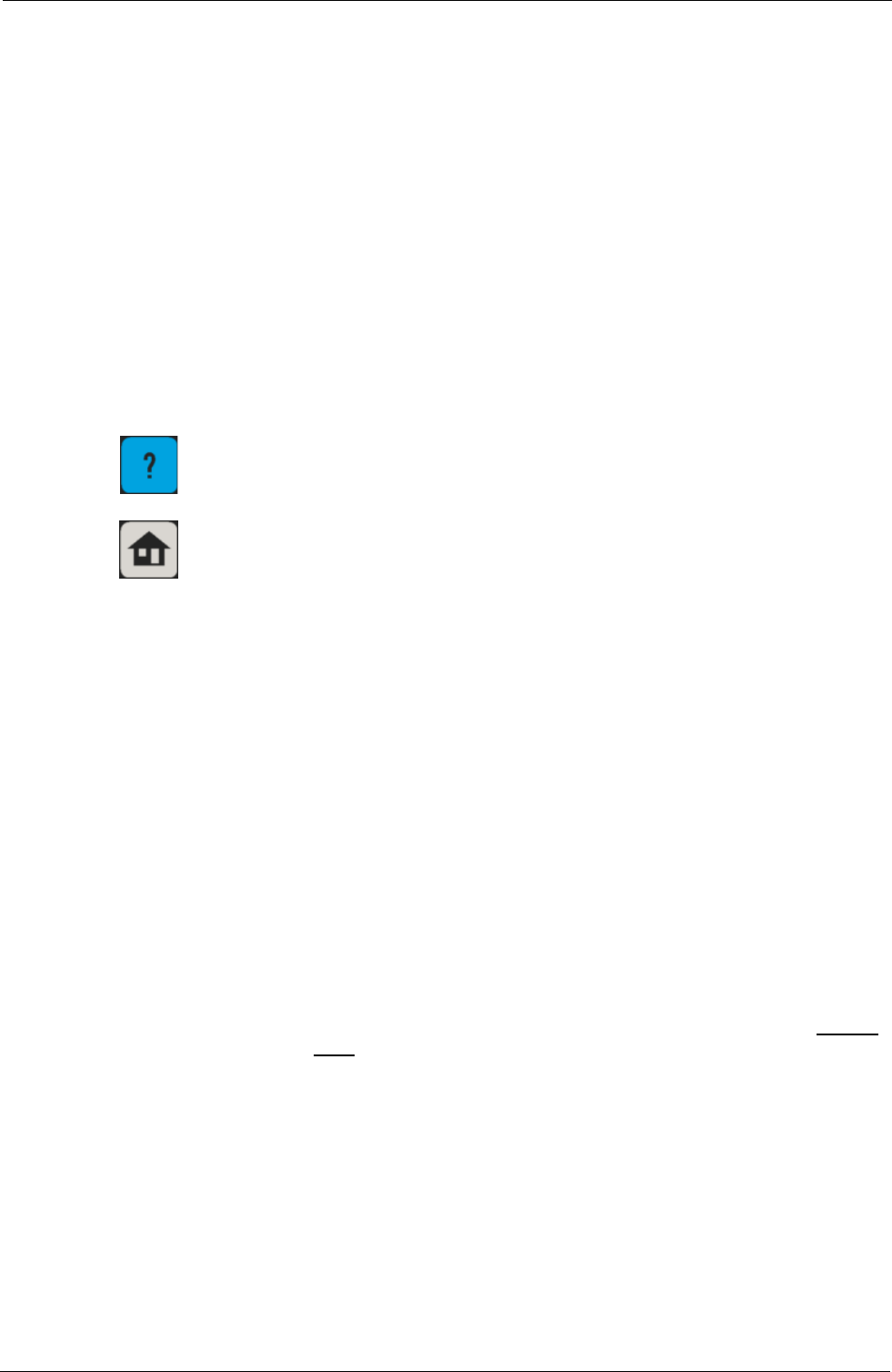
The help screen shows a typical screen from Tempus IC. It shows that there are three distinct
areas on the screen that give different types of information.
1. Status Bar This shows if the voice and data links are connected, if ECGs or
pictures are being transmitted and what the time is when recorded.
2. Process Instructions This area contains the graphical pictures and text instructions that
show you how to use the device. This takes the user through each
activity one or two steps at a time.
3. Touch Screen Buttons In this example there are two buttons at the bottom of the
touchscreen. In all cases the user will press the button on the bottom
right of the screen to progress onto the next step in the process.
Page 22 41-1001-00B
Tempus IC User/Operator Manual
Example of the Tempus IC Screen Layout
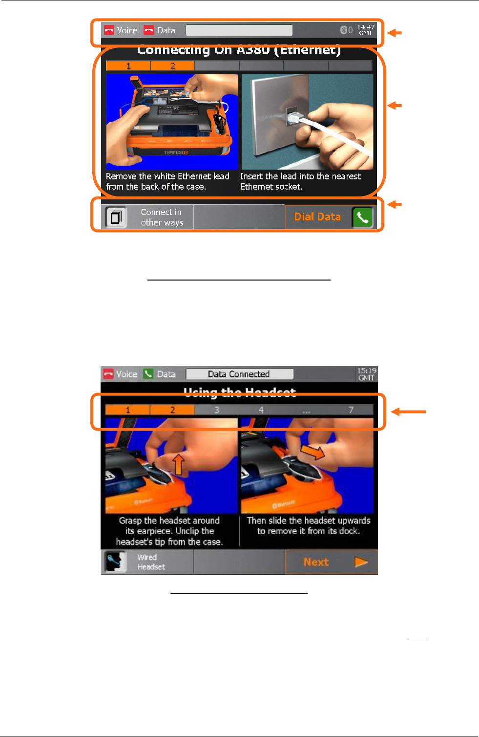
5.1.1.2 Progressing through Help Processes
As mentioned above, Tempus IC breaks all processes down into small steps. These steps are
shown on the screen in one or two at a time.
The user can see how many steps there are in any process by looking at the Process Ribbon
near the top of the screen.
Status bar
Help process
graphics and
instruction
Touch screen
buttons
Process
Ribbon
Example of the Process Ribbon
In the example shown above, the screen shows that the process has 6 steps and that the
device is showing steps 1-2.
The user follows the instructions given on the screen, ensuring that they review both the image
and the text. Once they have completed both steps they proceed onto the next steps by
pressing the Next touchscreen button.
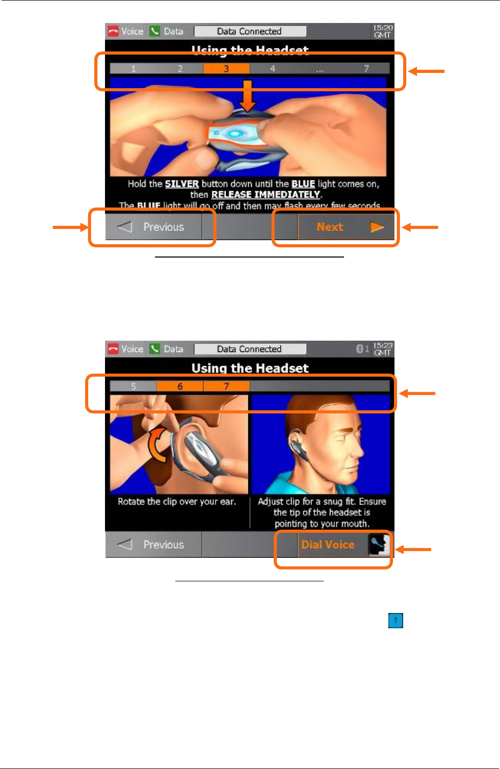
Pressing this will bring up the instructions for the next 1 or 2 steps in the process. Similarly
they can go back to earlier steps by pressing the Previous touchscreen button.
Page 23 41-1001-00B
Tempus IC User/Operator Manual
Process
Ribbon
updated
Example of the Middle Steps of a Process
Next button to
progress to
next step
Previous
button to
return to
last step
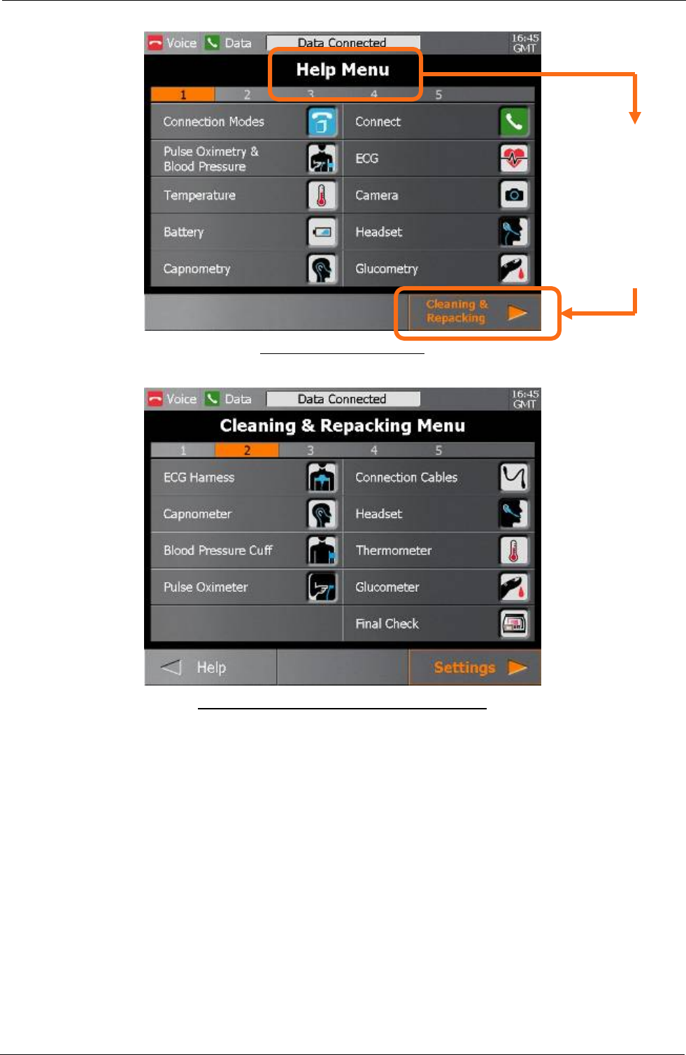
At the end of a process, the Next touchscreen button changes to show an icon that relates to starting the
action that the process has prepared for. So at the end of the process that has been shown in this example,
the user would start the voice link connection.
Page 24 41-1001-00B
Example of the End of a Process
5.1.1.3 Getting Help
As mentioned earlier, the user can get help at any time by pressing the button at any time.
This will bring up the Help Menu. There are multiple sequential menus covering different
aspects of using Tempus IC. For example, when the first Help Menu is on the screen, the next
menu (Cleaning and Repacking Menu) can be accessed by pressing the Next touchscreen
button.
Process
Ribbon
complete
Icon
shows end
of process
Tempus IC User/Operator Manual
Page 25 41-1001-00B
Example of the Help Menu
From the Help
Menu, press
the Next
button to bring
up the
Cleaning and
Repacking
Menu
Example of the Cleaning and Repacking Menu
The user can move backwards and forwards through the Menus by pressing the Next and
Previous touchscreen buttons.
Tempus IC User/Operator Manual
5.2 Explanation of the Tempus IC Screen
Tempus IC screen normally divides into two sections:
• Connection status and time of day at the top
• Instrument readings in the middle
Page 26 41-1001-00B
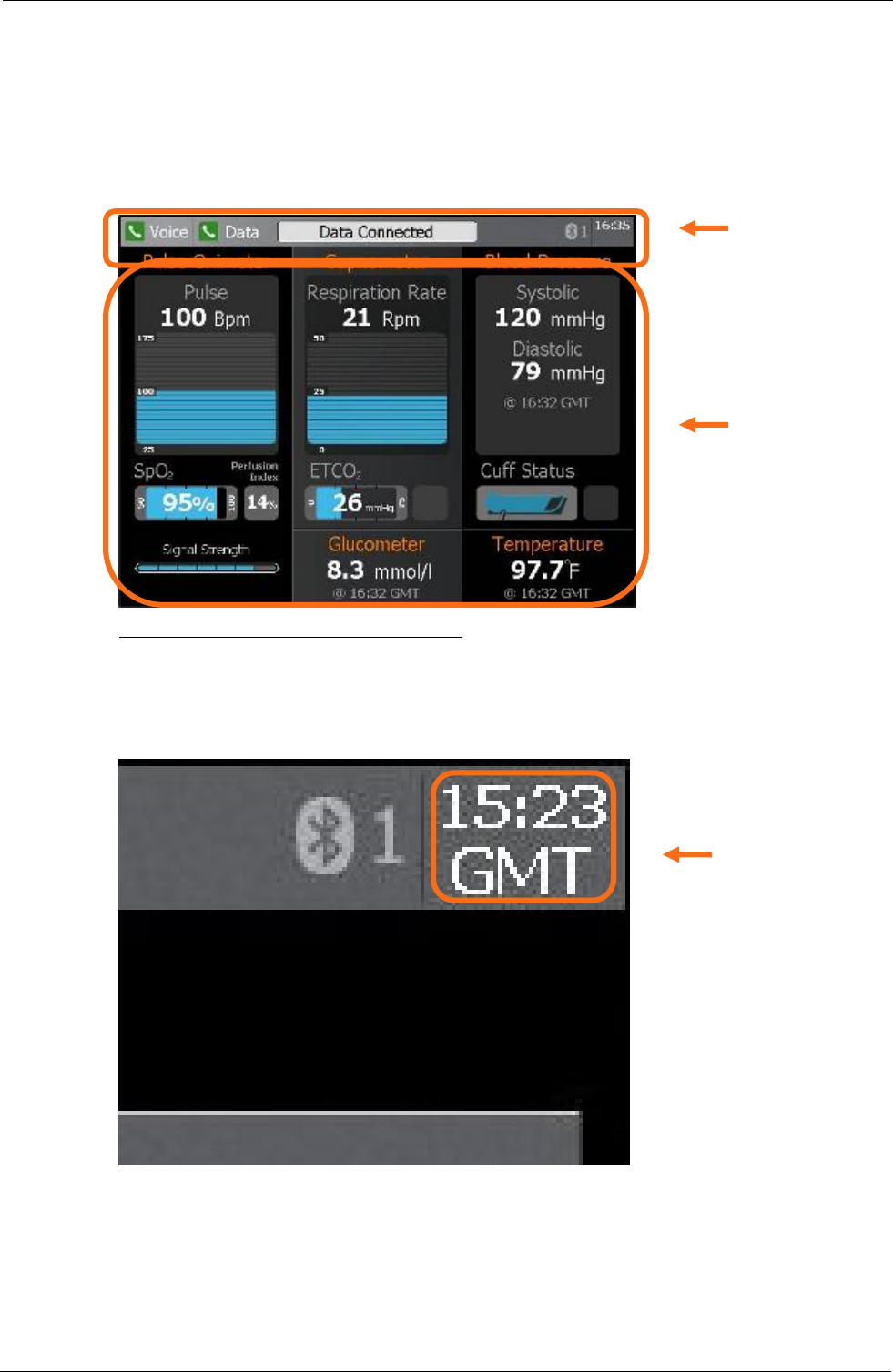
Example of the Tempus IC Screen Display
Status
bar
Instrument
Readings
5.2.1 Status Bar – Clock (Time Stamp)
The time of day is shown in Greenwich Mean Time (GMT), which is also known as Universal
Time Co-ordinate (UTC). Tempus IC has an internal clock which is automatically synchronised
to an accurate time reference at the Response Centre as soon as a call is made.
Time in GMT
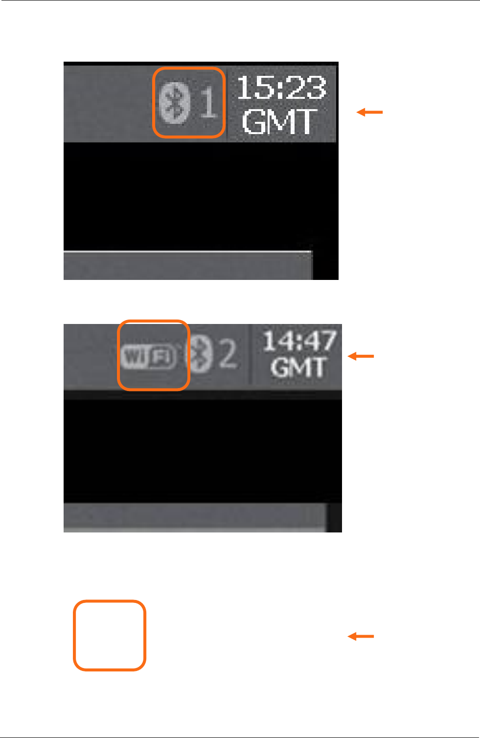
5.2.2 Status Bar - Bluetooth Indicator
The Bluetooth indicator identifies the number of Bluetooth sensor connected to the device, i.e.
1 sensor at this time.
NOTE: It does not identify the specific sensor connected to Tempus IC.
Tempus IC User/Operator Manual
Time of day is shown in Greenwich Mean Time (GMT), which is also known as Universal Time
Co-ordinate (UTC). Tempus IC has an internal clock which is automatically synchronised to an
accurate time reference at the Response Centre as soon as a call is made.
Bluetooth
Indicator
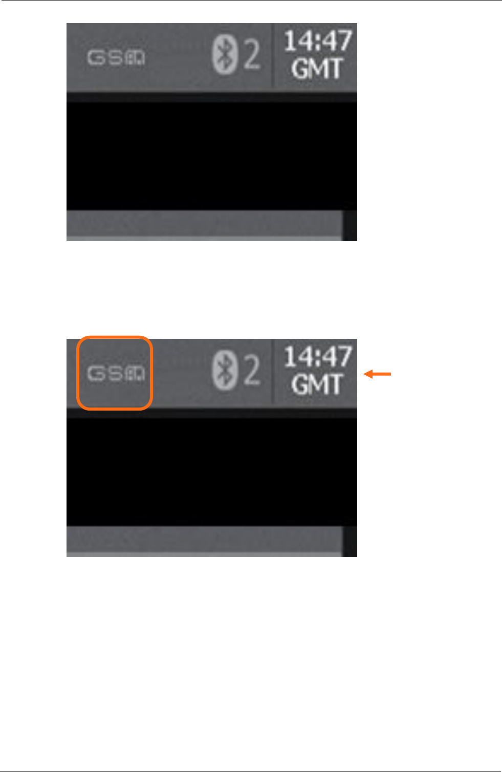
5.2.3 Status Bar - Wifi Indicator
This indicator is displayed when Tempus IC is connected to the Response Centre using WiFi
communications technology.
WiFi
Indicator
5.2.4 Status Bar - GSM Indicator
GSM Indicator
Page 27 41-1001-00B
Tempus IC User/Operator Manual
5.2.5 Status Bar - Video Indicator
This indicator is displayed when Tempus IC is connected to the Response Centre using GSM
communications technology.
Video Indicator
5.2.6 Instrument Readings
This section of the screen shows the results (if any) from the five different medical devices
(ECGs are displayed separately). Each of the five areas shows more than one piece of
information i.e. data taken, time taken and type of units are displayed. Descriptions of the
instrument readings are contained in the sections of this manual which describe each
instrument.
When iAssist help processes are displayed, they take up the space normally occupied by the
instrument readings and the status indicators.
Page 28 41-1001-00B

Tempus IC User/Operator Manual
Page 29 41-1001-00B
All of the measurements except blood pressure, temperature and ECG are continuous, that is
they are taken automatically without operator intervention. Data from these measurements is
sent automatically to the Response Centre in real-time (if the data line is active), otherwise the
measurements are memorised and sent when the data line is next active.
• Temperature measurements require the operator to physically take a reading.
• ECG measurements produce a lot of data which takes a few minutes to transmit to the
Response Centre. ECG measurements can be initiated manually by the operator or
remotely by the Response Centre.
All data which is generated by Tempus IC is automatically time-stamped.
5.2.7 Instrument Status Indicators
The Instrument Status indicators show what each instrument is doing. The status can be one
of the following:
Measuring The instrument is currently taking a reading
Idle The instrument is currently idle
On timer The instrument is making timed measurements (e.g. blood pressure) and
will make another measurement in due course.
Disabled The instrument is disabled, possibly due to a fault (see Troubleshooting in
section 10.4)
Additionally, further informative Status messages may appear during readings (e.g. press
’STOP’ on the touch screen o stop reading during a capnometer measurement).
When iAssist help processes are displayed, they take up the space normally occupied by the
instrument readings and the status indicators.
5.3 Device Sensors
Many of the measurements made by Tempus IC are continuous, but the ECG is only
measured when specifically initiated by the operator or Response Centre medical expert. All
the measurements except ECG are continuously transmitted to the Response Centre.
ECG data and video images take an appreciable amount of time to send to the Response
Centre, approximate times are as follows:
• 12 lead ECG – 2-3 minutes
• Low resolution video image - about half a minute
• High resolution video images – 2-3 minutes.
These times are for guidance only and are based on the worst case communications system
(off-aircraft satellite link running at 2.4Kbaud V22BIS) and may vary depending on the quality of
the connection.
5.3.1 Pulse Rate and Oxygen Saturation (SpO2)
Pulse rate and oxygen saturation are detected by the clip-on reusable finger probe. This probe
contains a visible (red) and invisible (infrared) light source and matching sensors. The sources
and sensors are arranged so that the lights shine through the patient's finger when it is inserted
into the clip. An amount of light also reaches the sensor via scattering within the skin.
It is also important that the sensor is not used on the same arm as the blood pressure cuff,
because false readings may occur when the cuff is inflated. In order to obtain accurate results
it is necessary to ensure that the patient's finger (and fingernail) is clean. Readings will not be
obtainable from patient’s with nail varnish or polish, consequently the Tempus IC is stocked
with nail varnish removing wipes in the foam block. In the event that these are needed, the
operator should follow the instructions on the wipe.

Tempus IC User/Operator Manual
Page 30 41-1001-00B
5.3.2 Blood Pressure
Tempus IC uses non-invasive techniques to measure the patient's blood pressure. A pump
within Tempus IC inflates the reusable blood pressure cuff around the patient's arm.
Circulating blood within the arm causes slight changes (oscillations) in the cuff pressure, which
can be detected and measured. As the inflation pressure changes, the systolic, diastolic and
mean arterial pressure can be measured.
This method of blood pressure measurement provides accurate readings provided that the
correct size of cuff is used and the specified operating precautions are observed.
Changing ambient pressures e.g. if Tempus IC is being used on an aircraft that is rapidly
descending or ascending, will not have an effect on the results provided by the blood pressure
monitor.
5.3.3 Electrocardiograph (ECG)
Electrical currents influenced by the cardiac impulse flow through the body tissue around the
heart. Tempus IC uses 10 electrodes (in a pre-set reusable apron configuration) placed mainly
on opposite sides of the heart to detect these currents.
The position of the electrodes is critical and so Tempus IC uses a specially moulded electrode
apron which has nine of the electrodes positioned in the correct places to pick up the signals.
The tenth electrode is positioned separately on the patient's leg. The electrode apron is made
of elastic material so that as it stretches to accommodate different sizes of patient, the positions
of the electrodes vary to maintain correct placement.
5.3.4 End Tidal CO2 (ETCO2) and Respiration Rate
The Capnometer CO2 Module is used to monitor continuous carbon dioxide and report the End
Tidal carbon dioxide (ETCO2), inspired CO2 and respiratory rate values of the intubated and
non-intubated adult, paediatric, infant and neonatal patient. The Capnometer CO2 Module is
used for the continuous measurement of CO2 (carbon dioxide) and respiratory rate.
Capnometer is a sidestream sampling system with a 50 ml/minute low sampling rate that is
used to measure the CO2. A tube inserted into the patient's nostrils detects samples of their
exhaled breath. The tube is connected to a pump within the Tempus IC, which draws the
sample through a measuring chamber.
In capnometer, infrared light is generated by the sensor and beamed through the sample cell to
a detector on the opposite side. CO2 from the patient that is aspirated into the sample cell
absorbs some of this infrared energy. The monitor determines CO2 concentration in the
breathing gases by measuring the amount of light absorbed by these gases. ETCO2 is
displayed as a numerical value in millimeters of mercury (mmHg), percent (%), or kilopascals
(kPa). Respiration rate is calculated by measuring the time interval between detected breaths.
5.4 Video Camera
A miniature colour video camera is mounted in the unit. Still images from this camera can be
sent to the Response Centre to provide the physician with a view of what is happening to the
patient.
Moving pictures from the camera are captured by the Tempus IC and displayed on the screen.
Individual pictures for transmission to the Response Centre are converted into digital
information and sent via the data communications channel.
Images can be sent in low-resolution or high-resolution mode. Low resolution images require
less time to transmit (typically more than 2 per minute), but high resolution images provide the
Response Centre with much more detailed pictures (normally requiring 2-3 minutes to
transmit). The selection of high- or low-resolution pictures is done by the Response Centre
operator, who will advise the expected time it will take to transmit the picture.
5.5 Voice and Data Communications
The Tempus IC uses a number of different communications technologies to connect to the
Response Centre. These can vary depending on the configuration of the Tempus IC, some
examples include:

Tempus IC User/Operator Manual
Page 31 41-1001-00B
• Using two telephone lines over low-speed satellite channels to connect voice and data to
the Response Centre. In low speed applications, two lines are needed, one for voice and
one for data.
• Using a single medium-high speed satellite channel to connect voice and data
simultaneously over a single line.
• Using a built-in Cell Phone to connect a simultaneous voice and data link over the wireless
network.
• Using a single analog land-line to connect a simultaneous voice and data call.
In all examples, the voice line uses an earpiece and microphone to enable normal telephone
type conversations with the physician at the Response Centre.
NOTE: User needs to connect the Tempus IC to the response centre every month for a test
patch

Tempus IC User/Operator Manual
Page 32 41-1001-00B
6 Setting Up
NOTE: The iAssist help processes on your Tempus IC may differ from this example iAssist help
process in the following sections. However the process always follows the same key
elements.
NOTE: Always ensure that you read the complete iAssist help process in order and do exactly what it
requires.
6.1 Setting up
6.1.1 Unpacking the Tempus IC
The Tempus IC is supplied from the factory in protective outer packaging. No special
precautions are required when unpacking the Tempus IC, other than to ensure that the outer
packaging material is retained in good order. The packaging material will be required when the
Tempus IC is returned for periodic preventative maintenance (described in section Error!
Reference source not found.).
6.2 Tempus IC Bag
Tempus IC bag is a custom design part made from moulded rubber. It is provided with a
shoulder strap and carry handle, the hard plastic parts of which are branded.
The bag provides a main storage area for Tempus IC (including windows to check the battery
status and turn the device on externally to avoid the user opening the bag to do this), a storage
area for the ECG harness, a range of pockets for consumables in the lid and a range of
pockets for accessories and consumables on the rear. The sides are fitted with studs to allow
the potential future attachment of small additional bags to houses power supplies and spare
batteries.
The lid of Tempus IC bag contains
1 vial of 10 glucometer strips
1 bottle of ECG electrode spray
5 disinfectant wipes
5 nail varnish removal wipes
10 thermometer covers and one application tool
3 disposable single-use lancets
The rear pocket of the Tempus IC bag contains:
The thermometer
The glucometer
Spare communications cables
The wired headset
An communications extension reel
A repack kit of consumables
The capnometer
2 disposable adult size nasal cannula
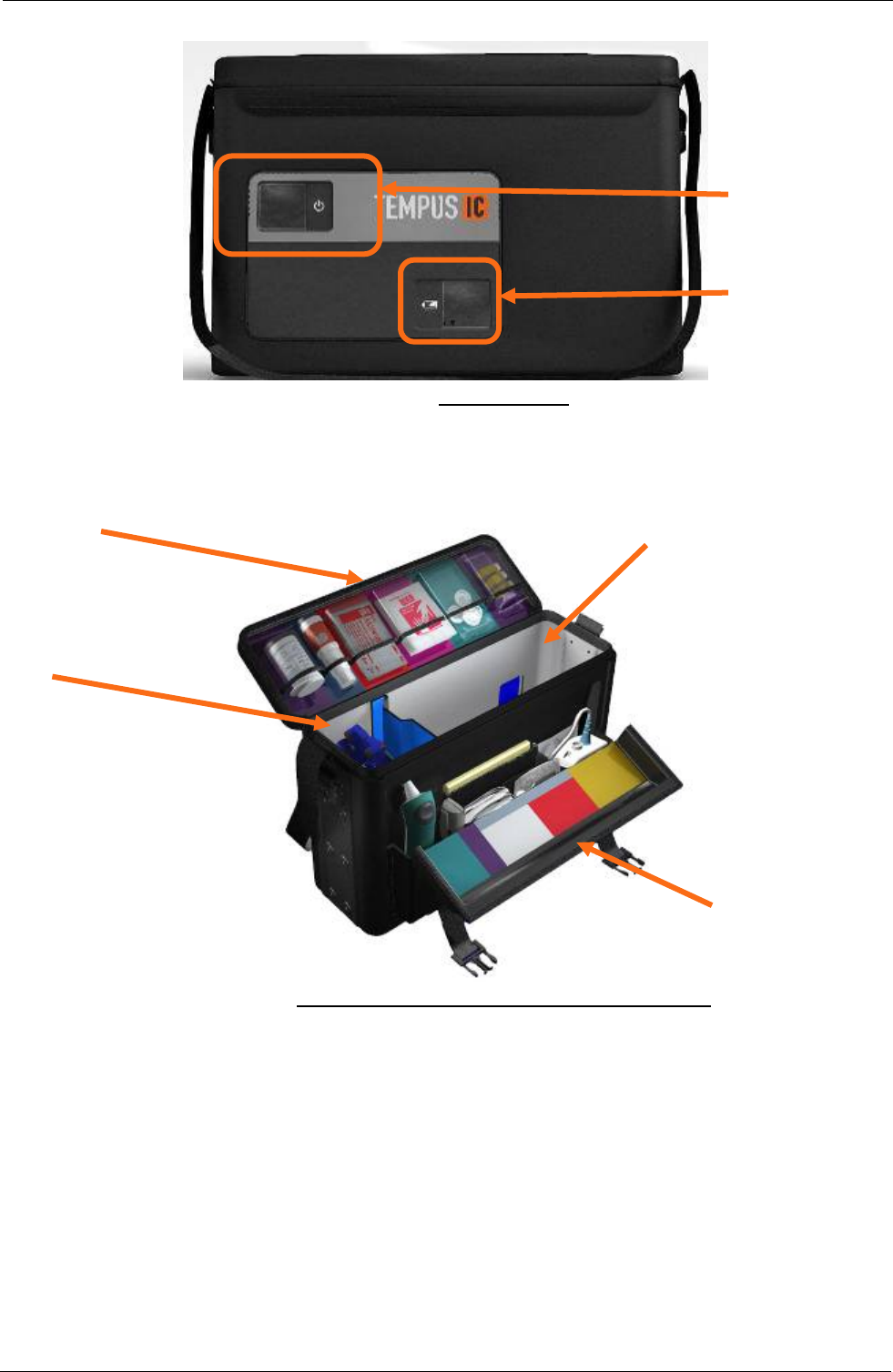
Tempus IC User/Operator Manual
Window to access
the ON/OFF
button
Window to access
the Battery charge
indicator
Tempus IC Bag
Consumables in colour-
coded pockets Tempus IC
location
ECG Harness
Accessories and
Consumables in colour-
coded pockets
Tempus IC Bag open with the Tempus IC removed
6.2.1 Ensure that Tempus IC is Packed Properly with Sufficient Consumable Items
Tempus IC is provided with, and should be stored with, the following consumable items:
• 5 cleaning wipes
• 5 nail varnish removal wipes
• Three blood pressure cuffs: child, adult and large adult
• Two cannula and filter packs,
• One full spray of ECG contact spray
• One bag of 10 thermometer covers and ring tool
• One Consumables Replenishment Kit
• One Glucometer Replenishment Kit
Page 33 41-1001-00B
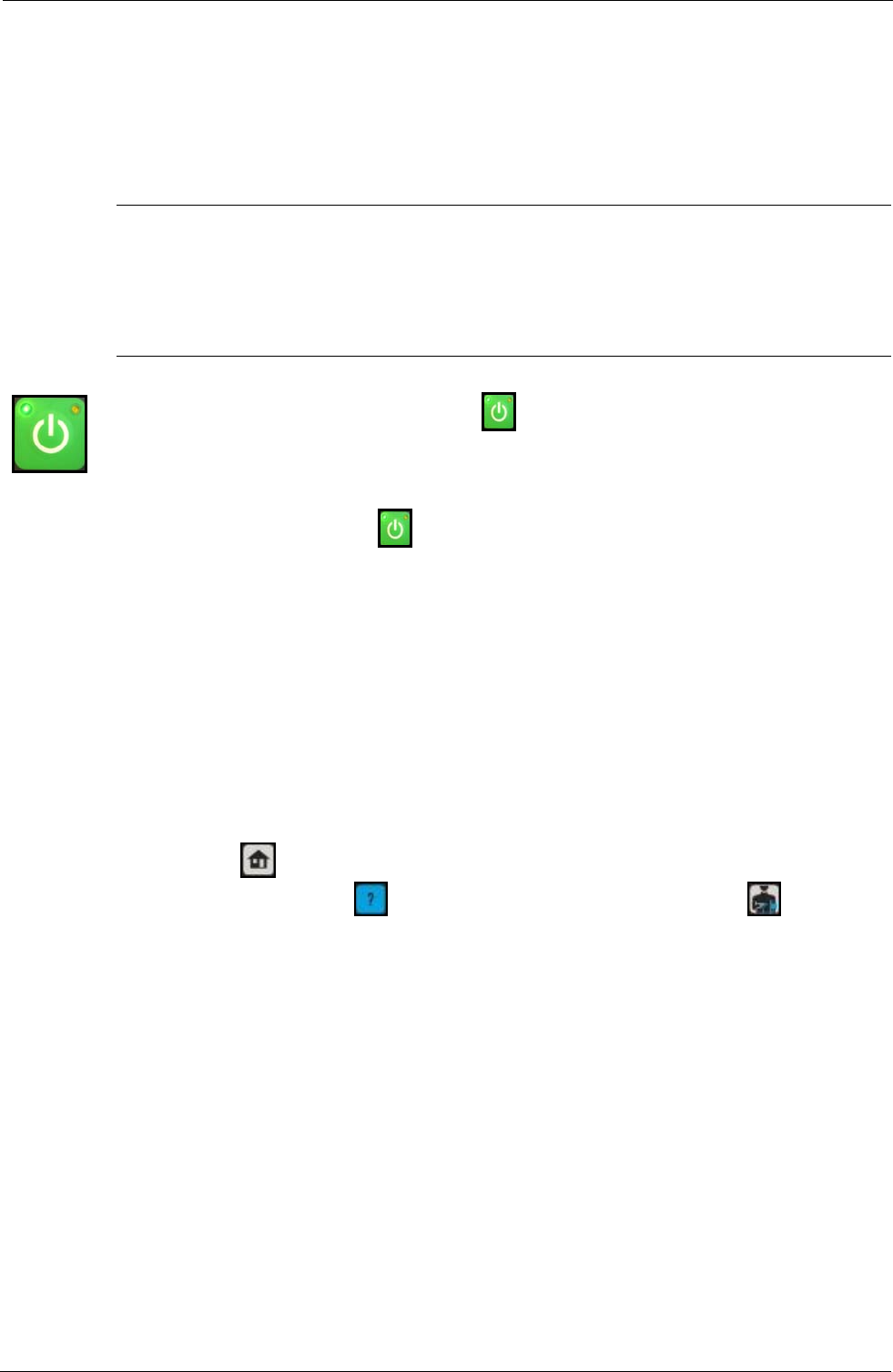
Tempus IC User/Operator Manual
Refer to section 11.1 for details of how to obtain further supplies of these
disposable items.
6.3 Switching On
6.3.1 Immediately after Switching On
Note
Tempus IC takes up to one minute to become ready for operation after switching on. It is
recommended that you switch on Tempus IC at the same time as you remove it from its
storage location rather than when you arrive at the patient.
To switch on Tempus IC, press and hold the button on the front panel for 3 seconds. Release
the button when the lamp at the top left corner of the button starts flashing green. Tempus IC is
ready for use when the LED shines green constantly. This takes about one minute. If no buttons
are pressed within 8 minutes, the unit will switch off automatically to save battery power.
Note that if the lamp on the button flashes red and green then there is not sufficient
power in the battery to start the device properly. In this case the battery must be replaced or
recharged before Tempus IC can be used.
Note: Do not press any of Tempus IC control buttons until the first iAssist help process
artwork is displayed on the screen.
After switching on, the Tempus IC goes through a pre-defined set of iAssist help processes.
These are:
• Making the data and voice connection
• Using the headset
• Taking a photo
• Blood Pressure and Pulse Oximeter
You can press to jump straight to the results screen, or any other button to get help for
that instrument e.g. pressing will bring up the first Help Menu or pressing will bring up
the help menu for the capnometer.
Page 34 41-1001-00B
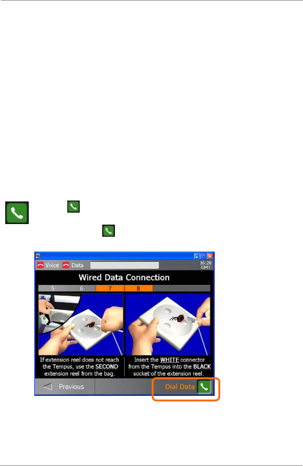
Tempus IC User/Operator Manual
7 Establishing Communication with the
Response Centre
7.1.1 Process for Connecting the Tempus IC
The first step for using the Tempus IC is to establish communication with the Response Centre.
To do this you will need to:
• Ensure the Tempus is set to use an appropriate communications Mode.
• Connect the Tempus IC to the Response Centre.
• Fit the Headset comfortably in your ear.
It is possible for a physician to use Tempus IC as a standalone diagnostic tool without
connecting to the Response Centre. Under these circumstances, just press the appropriate
measurement function button to access that function. It is still possible to be connected to the
Response Centre at any time by pressing the Connect button.
Tempus IC can also be left running with the data link connected but the voice link
disconnected i.e. if the Response Centre physician wishes to continue monitoring the patient
for a long duration but without keeping the Voicelink open with Tempus IC User. In this case
the Voicelink can be reconnected at any time by pressing the Connect button.
7.1.1.1 Making the Phone Connection
Press the button on the touch screen to make the Tempus IC dial and establish the voice and
data connections to the Response Centre.
As soon you press the button, the Wireless Headset screen will appear.
If the Response Centre cannot be contacted, this could be due to errors in the way that the
connection has been attempted (see section 10.4 of this manual for Troubleshooting
information). Help will be given in the form of iAssist help process, follow the instructions given
and wait for a few minutes before trying again.
Page 35 41-1001-00B
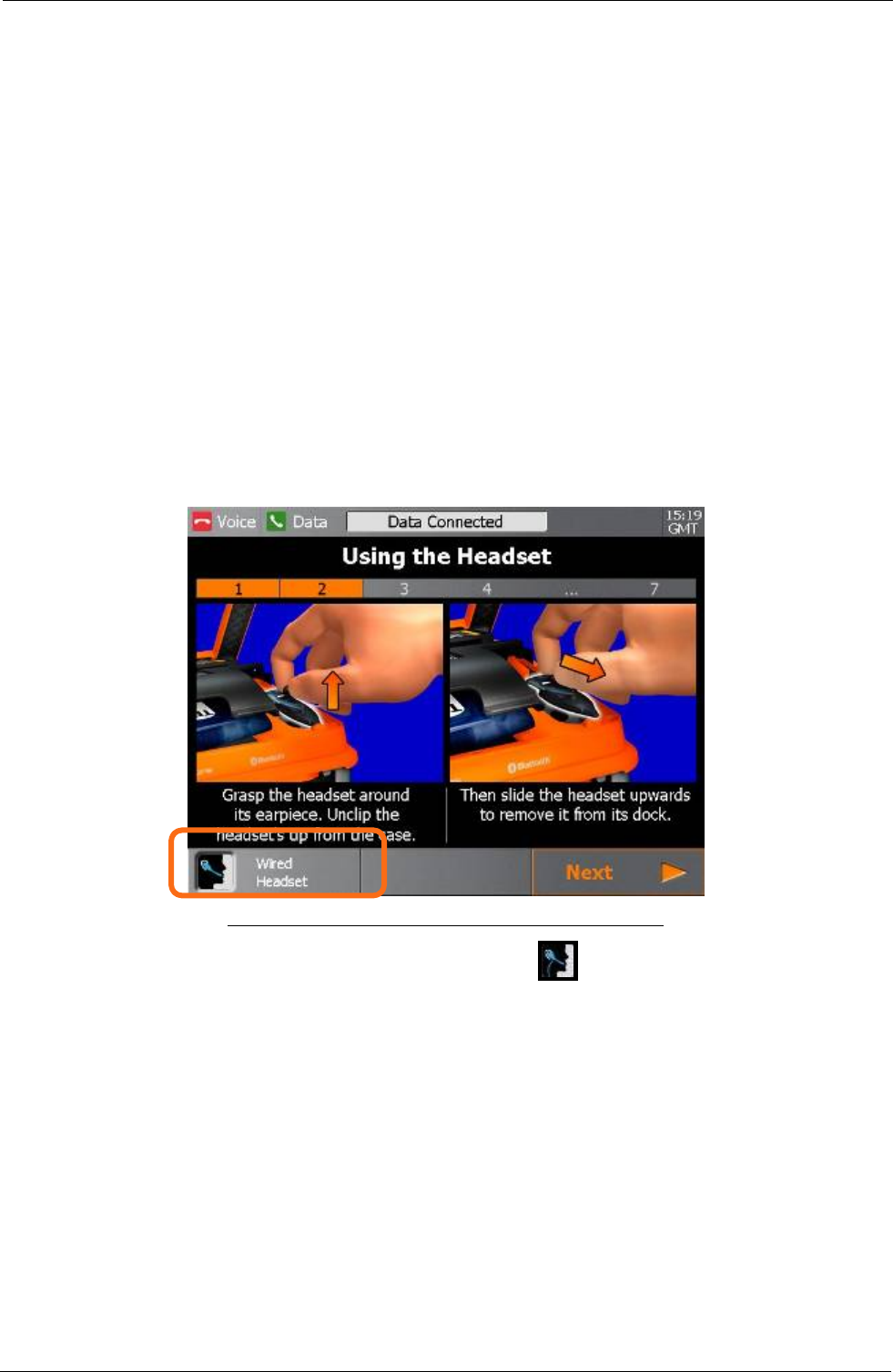
Tempus IC User/Operator Manual
If your Tempus has been configured for automatic redialling, then it will attempt to connect to
the Response Centre if the first call fails. The system will indicate the redial process by
displaying a number over the Data Link status indicator. The system will attempt a number of
redials (typically 4), and will display the corresponding number over the Data Link status
indicator bar.
7.1.1.2 Fitting the Headset and Making the Voice Connection
7.1.1.2.1 Wireless Headset
1. Remove the Headset from its storage position at the back of the device.
2. Fit the Headset into your ear.
3. The Headset will work equally well in either ear.
4. The Headset is a microphone as well as a speaker.
5. Speak clearly and the operator at the Response Centre will be able to hear you.
6. Note that the volume of the earpiece can be adjusted using the ‘-‘ and ‘+’ buttons on
the side of the Headset.
Example of the Wireless Headset IAssist help process
NOTE: To switch to the Wired Headset press the button on the touch screen as
identified in the above screen.
7.1.1.2.2 Wired Headset
1. Remove the Headset from its storage position at the bag.
2. Fit the Headset into your ear.
3. The Headset will work equally well in either ear.
4. The Headset is a microphone as well as a speaker.
5. Speak clearly and the operator at the Response Centre will be able to hear you.
6. Note that the volume of the earpiece can be adjusted using the ‘-‘ and ‘+’ buttons on
the side of the Headset.
Page 36 41-1001-00B
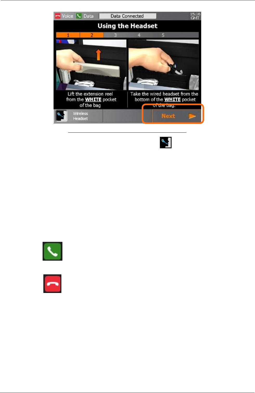
Tempus IC User/Operator Manual
Example of the Wired Headset IAssist help process
NOTE: To switch to the Wireless Headset press the button on the touch screen as
identified in the above screen.
7.2 Connection Status Indicators
NOTE: The iAssist help processes on your Tempus IC may differ from this example iAssist help
process in the following sections. However the process always follows the same key
elements.
NOTE: Always ensure that you read the complete iAssist help process in order and do exactly what it
requires.
The connection status indicators show whether Tempus IC is connected to the Response
Centre. There are separate indicators for the voice link and the data link.
The following symbols indicate the state of the links:
Call in progress ('connected')
No call in progress ('disconnected').
Note that the words 'connected' and 'disconnected' refer to whether there is a call in progress,
NOT whether the Tempus IC phone wires are plugged in.
7.2.1.1 Dialling Order and Indicators When Dialling
Once a voice or data link has been initiated, the “No call in progress” indicator will change to a
“Call in progress” indicator which will start to flash. The voice and data link indicators will flash
independently until each link has been connected.
While waiting for the voice link to connect, Tempus IC can be used to take measurements of
the patient e.g. blood pressure, pulse oximetry and a video picture, which will then be available
to the response centre as soon as the connections have been completed.
Page 37 41-1001-00B
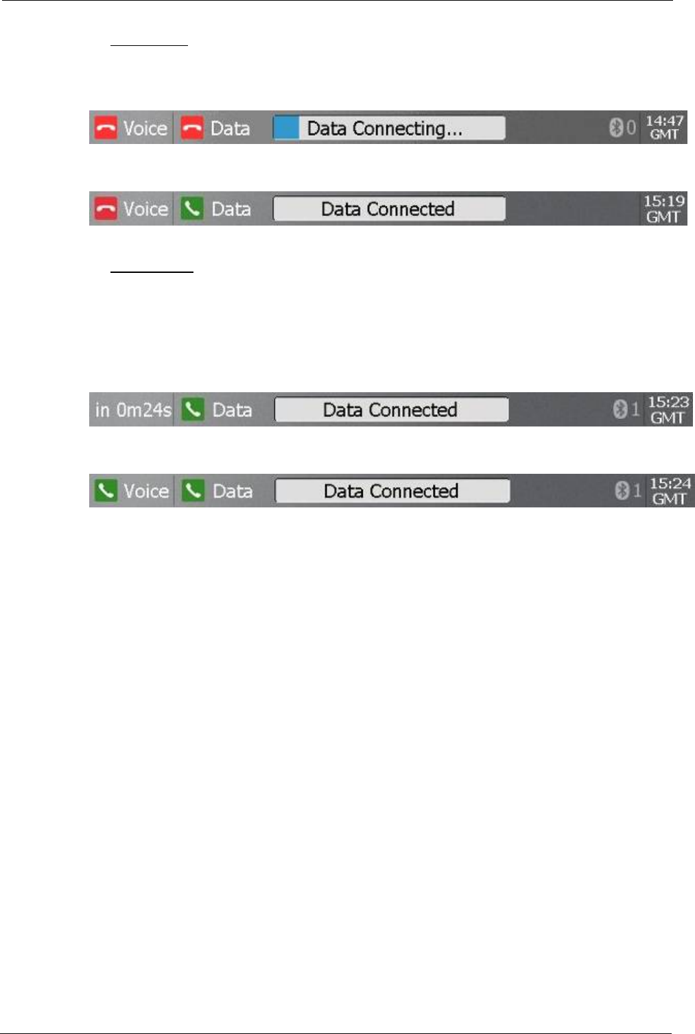
Tempus IC User/Operator Manual
7.2.1.1.1 Data Dialling
Once dialling has been initiated, text will appear giving a countdown to when the data link is
expected to connect. This is accompanied by a blue progress bar which grows as the time to
connection gets closer.
Once the data link has been established the text indicator will display “Data Connected” and
the “Call in progress” indicator which will stop flashing.
7.2.1.1.2 Voice Dialling
The voice link will start to dial as soon as the data link is connected. If the data link is taking
longer to connect than usual (as a result of difficulties with the communications channel) then
the voice link will dial within a preset time (typically 3 minutes 40 seconds).
In addition, a countdown will flash behind the “Voice Link?” status indicator to show how long it
can be before the voice line will start to dial, the voice link will typically dial before the
countdown is completed.
Once the voice link has been established the text indicator will display “Data Connected” and
the “Call in progress” indicator which will stop flashing.
NOTE: If your Tempus has a built in Cell Phone (GSM) phone built into it, then it will need
to log onto the network at the beginning of each call. This is shown by similar text
and a separate progress bar for logging on.
7.2.1.2 Automatic Redialling
If Tempus IC is configured to redial the voice or data links automatically then it will indicate that
a redial is taking place by displaying a number behind the “Call in progress” indicator.
7.2.1.3 Indicators Once Connections Have Been Established
Once the voice and data links have been connected, their status indicators will stop flashing. In
addition, once the data link has been established the progress bar will disappear and the
following text will be displayed.
7.2.1.4 File Transfer Status Indicator
When data files (either an ECG or a still video image) are being transmitted, the progress bar
shows how far the transmission has progressed. In the above screen, a data transfer is 6%
complete.
Page 38 41-1001-00B
7.2.1.5 Advanced Data Robustness (ADR)
Tempus IC software includes the unique, patented feature called ADR. ADR was developed to
reduce the problems encountered when transmitting data across satellite links. Satellite links
are noisy when compared to land line connections and this can cause data connections to fail.
An analogy of this is that when speaking over mobile phones, noise or pauses in the line will be
recognised by the callers. They wait for the pause or noise to pass and then continue their
conversation. With data connections this does not happen as the modems do not understand
or recognise the noise or delays and so drop the connection as soon as noise is present.
This causes poor reliability on data connections over satellite links. Consequently, ADR
manages the existing connection when the line is noisy so that the connection is not dropped.
When ADR becomes active, it presents as:
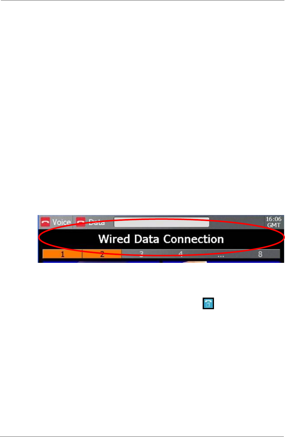
Tempus IC User/Operator Manual
Page 39 41-1001-00B
• the da een tick to a flashing yellow tick to indicate that
• e activity – the Tempus will still record data but none of the new information will
• dicate the device is
• call
• sume once ADR activity ceases
en
7.3 Com es
Centre using different communications technologies.
connect
Mode it is in with a banner at the top of the Connection IAssist help
ta link status indicator tick changing from a gr
ADR is in operation
a delay in the data lin
be transmitted to the Response Centre until ADR has ceased operation
the data connection tick changing from flashing yellow to solid yellow to in
reconnected but is uploading data recorded in the interval (this will last for a few seconds only)
the voice line will operate normally except for simultaneous voice and data calls where the voice
will be interrupted until ADR has ceased operation
any file uploads will be suspended while ADR is active but will re
If there is so much noise on the telephone line that it is not practical for ADR to manage it th
the system will disconnect the connection. In this event, Tempus IC can be re-connected to
the Response Centre normally.
munications Mod
Tempus IC can connect to the Response
Examples of these include conventional 2k4baud satellite communications systems and analog
landlines. Both of these examples require connecting the Tempus using the white cable. In
addition, Tempus IC may be fitted with built-in communications devices which will enable it to
connect using the GSM Cell Phone network or via an Ethernet (LAN) connection.
In order to take advantage of these different technologies, Tempus IC is pre-set to
using different communication “Modes”. Each Mode is supported by a full set of graphical
connection iAssist help process that provide the User with instructions specific to connecting
using that technology.
Tempus IC shows what
process.
Tempus IC will stay in this Mode until it has been set to another Mode (even if it has been
7.3.1.1 Cha
You can change the Mode that Tempus IC is set to by pressing
turned off and on again).
nging Modes
from the Help Menu
es
re available to use
7.3.1.2 Usin
ailable on each Tempus IC are dependent on the requirements of each
that each Mode may have a different set of instructions for connecting, fault finding
that if one Mode cannot be used then another may be usable
IAssist help process. This will bring up the Communications Mod Menu.
NOTE: Follow the instructions provided on the Menu shows what Modes a
(See Section 7.10.2.1).
g Available Modes
The Modes that are av
User. Refer to the Modes Menu on your Tempus for specific details of each Mode that is
available.
Remember
and repacking. Consequently it is vital that you remember to read and follow what each iAssist
help process says at all times.
It is also important to remember
in its place e.g. if GSM coverage is not available then a landline connection may be useable
instead.
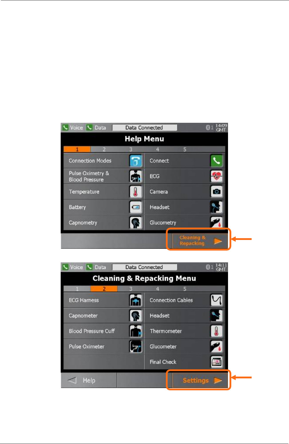
Tempus IC User/Operator Manual
7.3.1.3 Changing the Connection Mode
1 Tempus IC is capable of connecting in a number of different modes e.g. for different
locations, satcoms or communications configurations. Each Tempus will be supplied
programmed with the modes that the customer needs based on their requirements.
2 The User should follow the process detailed below to access the menu of available
modes from which to make a selection.
3 Switch Tempus IC on by pressing the green ON/OFF button on the front panel.
4 When the unit has switched on (after about a minute), press the “?”button on the right
hand side of the front panel.
5 Press the “Yes” button on the touchscreen.
6 You will then see the Help Menu
1. Press the
touchscreen
here
2. Then press
the touchscreen
here
Page 40 41-1001-00B
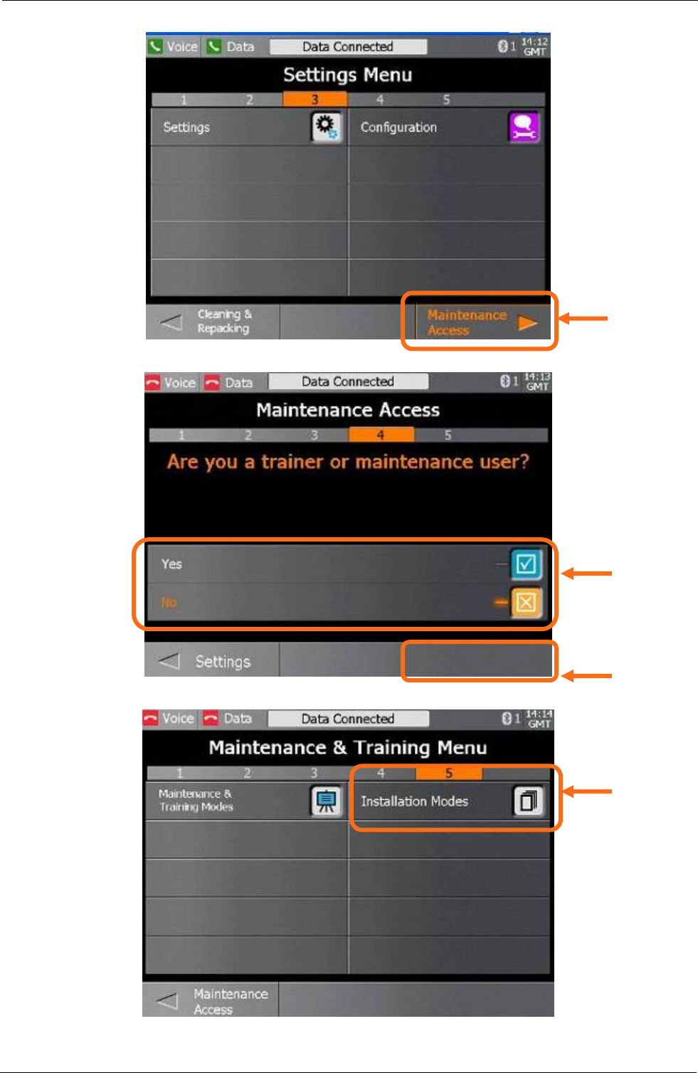
Tempus IC User/Operator Manual
Page 41 41-1001-00B
3. Then press
the touchscreen
here
4. Then confirm
that you are
maintenance
personnel
5. Then press
the touchscreen
here
6. Then press
the touchscreen
here to access
the list of
available
communications
modes
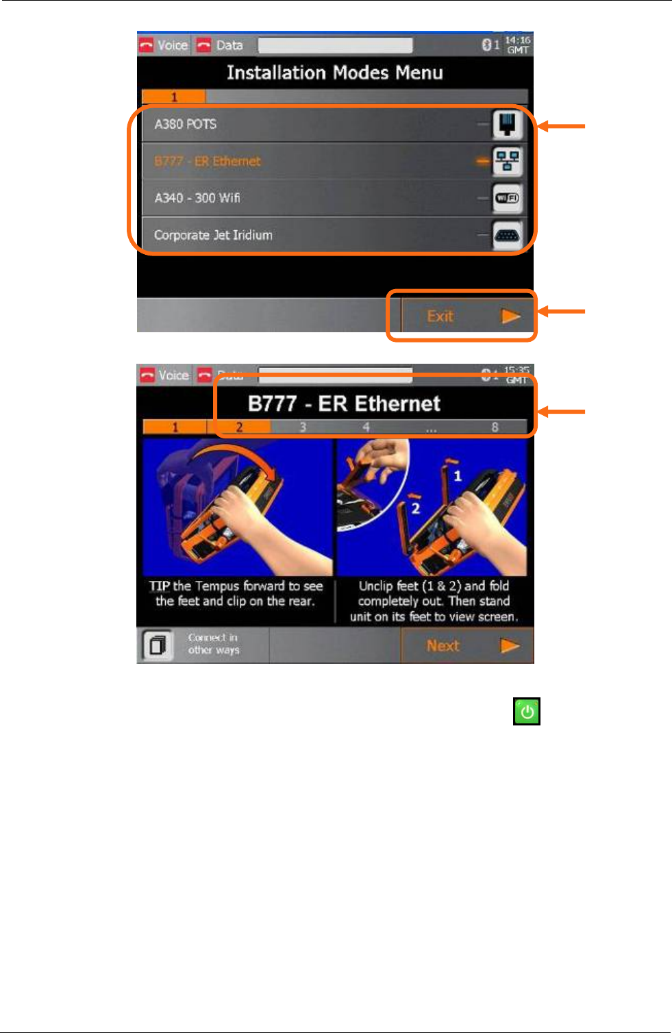
Tempus IC User/Operator Manual
7. Then make
the relevant
selection by
pressing on one
of the buttons
shown here –
CHECK the title
of the mode is
what you want.
Page 42 41-1001-00B
8. Then confirm
the selection by
pressing here.
9. You can
confirm that the
correct selection
has been made
by checking the
title.
10. You can now power the unit down by pressing the green ON/OFF button on the front
panel.
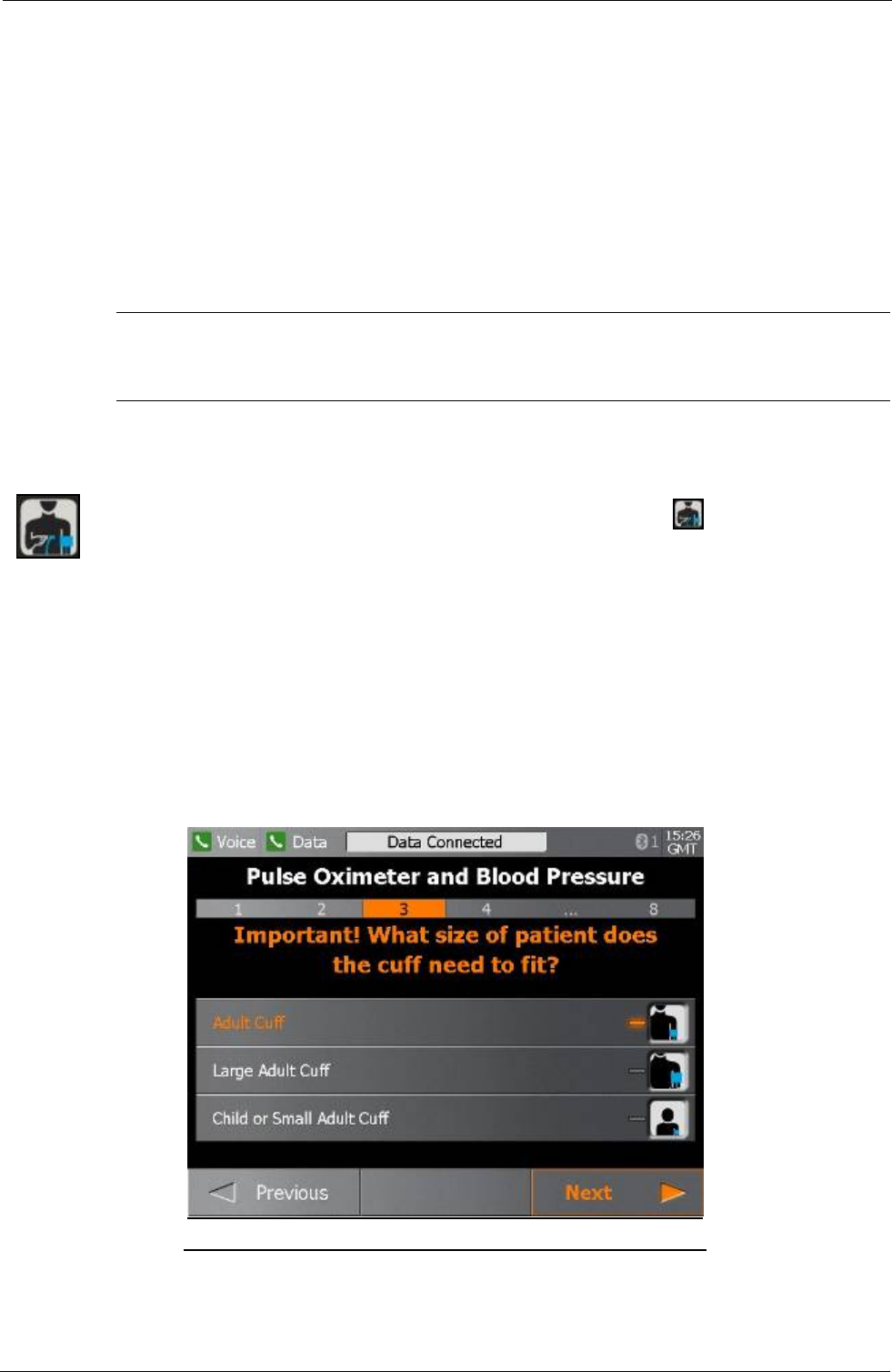
Tempus IC User/Operator Manual
8 Taking Medical Readings
NOTE: The iAssist help processes on your Tempus IC may differ from this example iAssist help
process in the following sections. However the process always follows the same key
elements.
NOTE: Always ensure that you read the complete iAssist help process in order and do exactly what it
requires.
Tempus IC is intended for use on one patient per incident. It must not be used on more than
one patient because Tempus IC has no way of associating a measurement with a particular
patient.
WARNING
It is essential to switch off the Tempus IC in between different patients to avoid
confusion between different patient records.
8.1 Blood Pressure and Pulse Oximeter
To activate the Blood Pressure & Pulse Oximeter function, press the button on the device. The
first Blood Pressure & Pulse Oximeter help screen will appear.
Follow the instructions provided on the iAssist help process to activate Blood Pressure & Pulse
Oximeter.
Select the correct size blood pressure cuff from the storage compartment (the normal size adult cuff
is highlighted on the Blood Pressure And Pulse Oximeter Help Screen shown on the device).
The cuff must fit comfortably on the upper arm. To connect and connect the tube to a cuff, insert
using a twisting motion
Example of the Blood Pressure And Pulse Oximeter Help Screen
Page 43 41-1001-00B

Tempus IC User/Operator Manual
Page 44 41-1001-00B
WARNINGS
The Tempus IC is not for use on neonates (young babies).
The Tempus IC is not intended for long term patient monitoring. There are no audible or
visible alarms.
Reposition the oximeter probe at least once every 1hour to allow the patient's skin to
respire.
SpO2 sensor should snugly fit the finger without straining it and if not alternative fingers
should be tried.
The Tempus IC will not operate effectively on patients who are experiencing convulsions
or tremors.
Prolonged or repetitive use of the blood pressure cuff may harm skin integrity and
circulatory status. Observe the limb concerned to check that circulation is not impaired
Notes
Dyes introduced into the bloodstream, including methylene blue, indocyanine green, indigo
carmine and fluorescein may cause an inability to determine accurate SpO2 readings.
Any condition that restricts blood flow, such as use of a blood pressure cuff (other than the
Tempus IC cuff used in accordance with the instructions herein) may cause an inability to
determine accurate pulse and SpO2 readings.
Compression or restriction of the blood pressure hose or cuff, or induced movement or vibration
may prevent the monitor from taking a reading.
SpO2 measurements may be adversely affected in the presence of high ambient light levels. If
necessary, shield the sensor area (e.g. with a towel).
Remove fingernail polish or false fingernails using the wipe provided before applying SpO2
sensors. Fingernail polish or false fingernails may cause inaccurate SpO2 readings.
Performance and safety test data are available on request from the address in section 1.1.
Significant levels of dysfunctional haemoglobins, such as carboxyhaemoglobin or
methemoglobin will affect the accuracy of the SpO2 measurement.
The graphical displays of pulse rate, SpO2 and pulse strength are not proportional to the pulse
volume.
If the finger selected does not give good results, this could be due to poor perfusion of blood.
Ensure that the finger is inserted all way into the clip, or try taking a reading on another finger.
The Pulse Oximeter must be on the opposite arm to the blood pressure cuff. The arm of
the patient must be kept still and either be horizontal to the shoulder (if the patient is laying
down) or below the shoulder (if the patient is sitting upright).

Tempus IC User/Operator Manual
IMPORTANT
You must use the right size of blood pressure cuff to suit the patient,
and you must tell the Tempus IC if you are using the Large cuff or Child cuff.
The cuffs are marked as follows:
Normal adult (23 – 33 CM). Cuff is coloured BLUE.
Large adult (41 – 40 CM). Cuff is coloured DARK RED.
Child or small adult (12 – 18 CM). Cuff is coloured BLACK.
IMPORTANT
The Pulse Oximeter must be on the opposite arm to the blood pressure cuff.
CAUTION
OneTime® nail polish remover is flammable. Keep away from heat and flame. Use
adequate ventilation. Exposed pad should be placed on glass or tile surface only. FOR
EXTERNAL USE ONLY. KEEP OUT OF THE REACH OF CHILDREN.
8.1.1 Understanding the Pulse Oximeter Results
The Pulse Oximeter display has four data elements plus a status indicator. Measurements are
made continuously and updated in real time. Measurements are sent in real time to the
Response Centre provided that the data link is active.
The Pulse section contains a bargraph and digital display of the patient's pulse rate, in beats
per minute (Bpm).
• Note that extreme pulse rates above 200 Bpm or below 50 Bpm are outside the range of
the bargraph display but will be shown accurately on the digital display.
The signal strength bargraph shows the how well the pulse sensor is detecting the pulse. The
amplitude of the indication indicates the quality of detection. If the indication on the Signal
Strength meter is low, or becomes low, then the finger sensor should be repositioned.
The SpO2 reading indicates the oxygen saturation of the blood, and displays the result in
bargraph and digital form.
The status bar shows the status of the Pulse Oximeter, which should normally be 'Measuring'.
8.1.2 Understanding the Blood Pressure Results
The Blood Pressure display has three elements plus a status indicator. Measurements are
normally made every five minutes via an automatic timer. Note that when the unit is in timer
mode, pressing will cause a reading to be taken. If the unit is taking a measurement,
pressing will cause the reading to be stopped. If the cycle is stopped, the status indicator
below will read “dle” to indicate that the unit is no longer operating.
Measurements are sent to the Response Centre every time they are made, provided that the
data link is active.
Blood pressure measurements are time stamped, and the time that the last measurement was
made is shown at the top of the Blood Pressure section. The Systolic and Diastolic
measurements are shown beneath the time.
Page 45 41-1001-00B

Tempus IC User/Operator Manual
The status bar shows the status of the Blood Pressure Monitor, which should normally be 'On
Timer' when the system is waiting between measurements, or 'Measuring' when a
measurement is actually being made.
8.1.3 Blood Pressure Monitor Error iAssist help process
The Blood Pressure Monitor will automatically display iAssist help process in the event that it
encounters problems in taking a measurement. The problems that it can encounter may often
have a fairly simple solution, consequently, the iAssist help process attempt to guide the
Operator through some basic checks that can be made.
Most of the time, the problems that the monitor experiences are related to being able to build
the correct pressure in the cuff and then maintain and release the pressure at the correct rates.
NOTE: All four of the iAssist help process may be produced if the Monitor has been activated
but not connected to the patient e.g. if only the Pulse Oximeter is being used.
8.1.3.1 Leaks
If the Blood Pressure Monitor is leaking, then this could be due to a poor connection to the cuff
or a leak in the cuff and the Monitor will display instruction. If these are the causes, re-
establishing the cuff connection and/or changing the cuff to another (if the new cuff size fits the
patient) may resolve the issue.
IMPORTANT: Follow the on screen help steps to rectify the error
8.1.3.2 Overpressure
If the cuff is compressed in some way, the Monitor may read an overpressure error and the
Monitor will display instructions. This may be caused by the cuff being fitted improperly, by the
cuff being compressed within the patient’s elbow or by the cuff being compressed against a
surface.
IMPORTANT: Follow the on screen help steps to rectify the error
8.1.3.3 Time-out
If the cuff is subjected to movement, it will attempt to retake the reading. If the Monitor
consistently cannot take a reading, the Monitor will display instructions. The potential causes of
this include improper cuff placement on the patient, induced movement into the cuff from
moving bodies next to the patient or that the patient himself is moving or speaking and thus
inducing movement into the cuff.
IMPORTANT: Follow the on screen help steps to rectify the error
8.1.3.4 Weak signal
If the signal from the cuff is too weak, the Monitor will display instructions. Potential causes of
the problem include blockages, or knots in the hose and a cuff that has been loosely fitted.
IMPORTANT: Follow the on screen help steps to rectify the error
8.2 Electrocardiograph (ECG)
To activate the ECG function, press button on the device
8.3 The first ECG help screen will appear.
8.4 Follow the instructions provided on the iAssist help
process to activate ECG.
Page 46 41-1001-00B
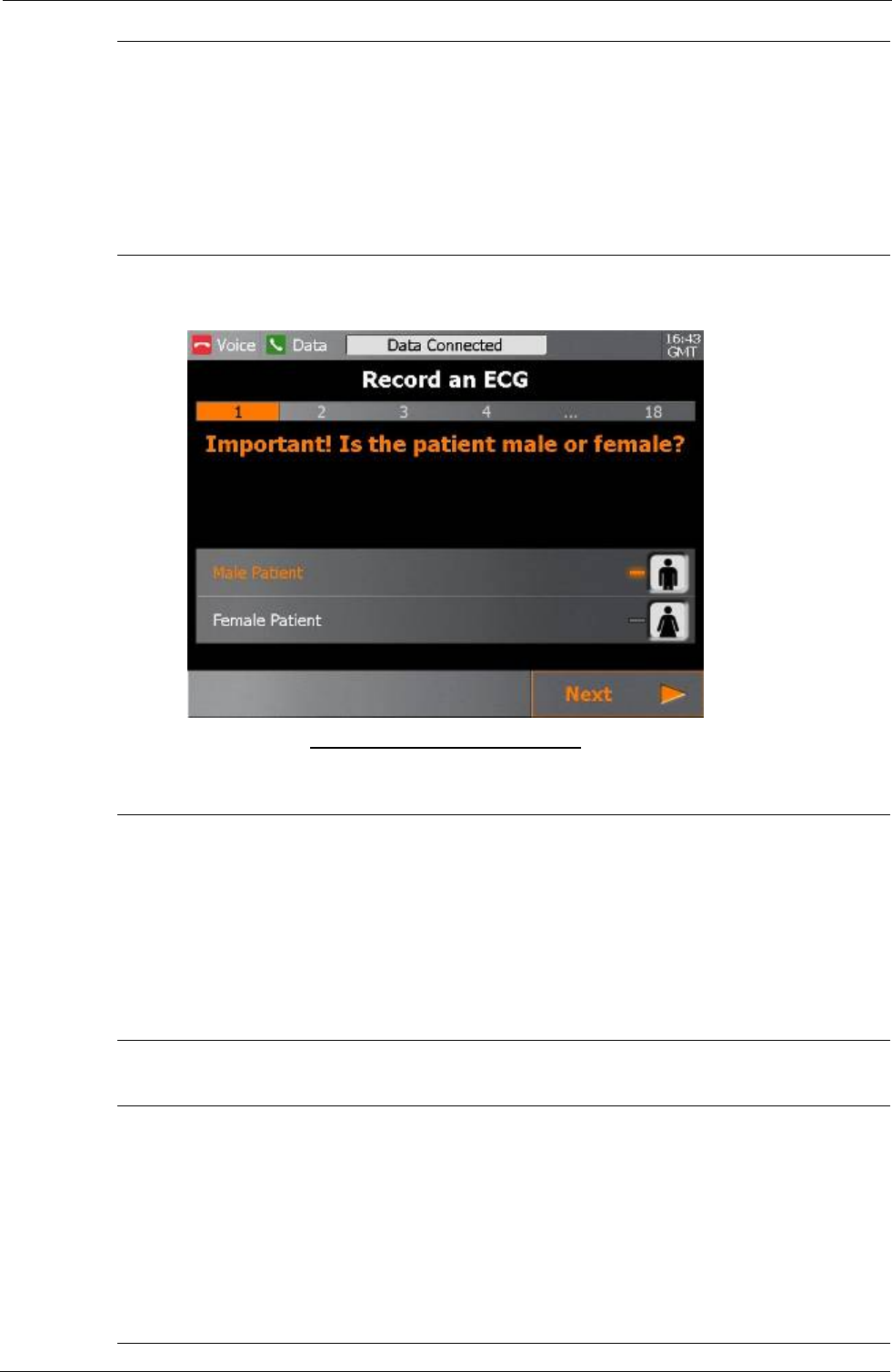
Tempus IC User/Operator Manual
WARNINGS
Tempus IC should not be used on patients undergoing defibrillation. Tempus IC is
protected against defibrillator discharge but rate meters and displays may be
temporarily affected during defibrillator discharge but will rapidly recover.
Tempus IC will not operate effectively on patients who are experiencing convulsions or
tremors.
Example of the ECG Help Screen
CAUTIONS
The electrodes of the ECG apron must be applied carefully.
Care must be taken to ensure that the electrodes do not contact live (electrical) parts or
earthed metal parts of local systems or structures.
The ECG spray is not to be used on broken or irritated skin
Note
Whilst the ECG harness fits many patients, one size cannot fit all patients. Consequently, the
ECG data collected may not be of diagnostic quality for some patients.
The leads and cables of the ECG should be checked for fraying, tears, knots or other signs of
damage before and after use.
The ECG spray is not a disinfectant. If the ECG contact spray goes into a person’s eyes, it may
be washed out using clean water.
Page 47 41-1001-00B
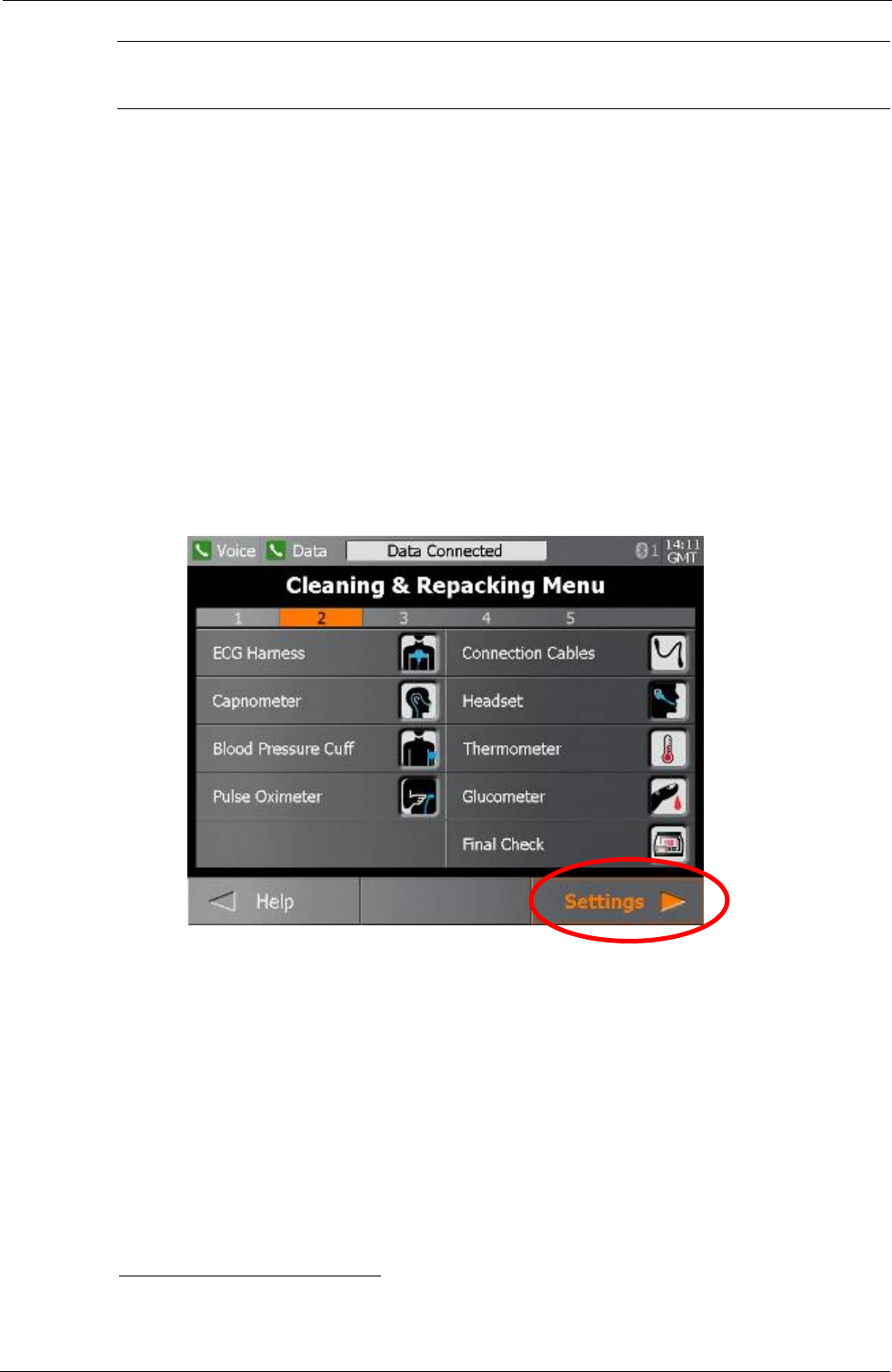
Tempus IC User/Operator Manual
The ECG spray bottle is marked with a label reading “USE BY:” and then giving a date. All
bottles of fluid must be discarded once this date has been reached.
The Tempus IC is now monitoring the patient's ECG, but is not recording the information. The
traces move across the screen from right to left, erasing and replacing old readings as the
monitoring progresses. It takes ten seconds for the trace to cross the screen.
The displayed waveforms may be partially or totally disrupted if,
• The patient is moving or talking
• The harness is not connected properly
• The harness is not positioned correctly.
The bottom of the screen shows the current status of the ECG settings. The most important of
these are:
Mains filter set to 50Hz. This should either be set to 50Hz1 or 60Hz. ECG systems can pick
up interference from mains electricity supplies. This interference appears on the screen as
regular interference patterns. An internal filter is provided to remove this interference. Details
of how to change this setting are contained in section Error! Reference source not found..
8.4.1 Monitoring an ECG
To record an ECG, press ‘record’ on the touch screen. The display will change to the
Recording screen.
1 Hz means Hertz, or cycles per second. In North America, mains electricity supplies operate
at 60Hz; most of the rest of the world uses 50Hz. In aircraft, although there is no actual mains
supply, the filter should normally be set to 50Hz.
Page 48 41-1001-00B
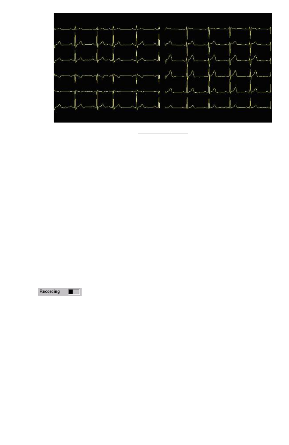
Tempus IC User/Operator Manual
Monitoring an ECG
Recording an ECG takes ten seconds. It is essential that the patient is relaxed and does not
talk or move while an ECG is recorded. If the patient is moving then the muscle movement can
produce small electrical signals (known as “artefact”) into the ECG. An ECG containing artefact
may not be clear enough for a medical professional to make a diagnosis so it is important that
the patient remains completely still during the recording.
Wait for the ECG trace to stabilise (like the trace shown above), ask the patient to breath in and
out and then to hold their breath for 10 seconds before pressing ‘record’ If the trace does not
stabilise, check the following:
• Patient should not be moving
• The apron should be aligned correctly
• The wrist electrodes should be on the correct sides
• The hip electrode should be on the left hip
• All the electrodes should be in good contact with the skin (use plenty of the spray if in
doubt).
8.4.2 Recording an ECG
When an ECG is being recorded, the word 'Recording' and a progress indicator bar
appear on the screen. This indicates that the ECG is being recorded, and the
progress bar shows how the recording is progressing. When the bar reaches the right hand
edge of the box, the recording is complete.
Once the recording is complete, the results will be displayed as shown in the following picture.
Page 49 41-1001-00B
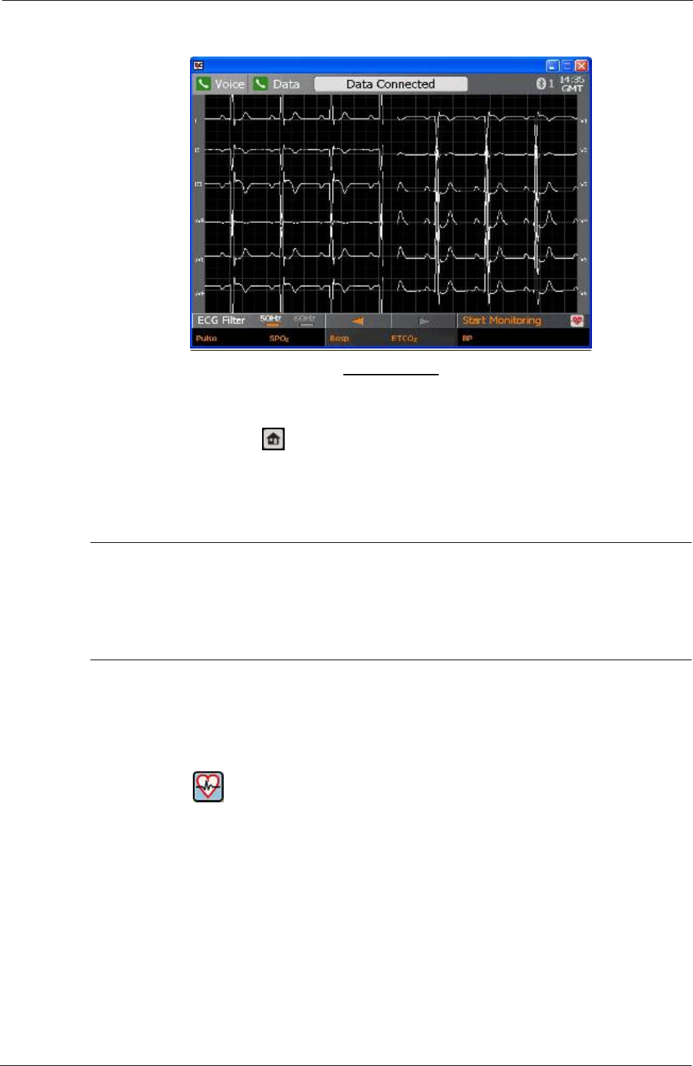
Tempus IC User/Operator Manual
ECG Recorded
If the Tempus IC is connected to a Response Centre, it will automatically start to transfer the
ECG file.
At this point you can press to close the ECG view to return to the main screen or you can
press ‘monitor’ on the touch screen to return to monitoring mode. Note that if you turn the ECG
off at this point and then restart the ECG function later during the same incident (without
switching the Tempus IC off), these results will be shown again. This means that you can view
the last ECG that was recorded from the patient.
CAUTION
It is essential that the Tempus IC is switched off before it is connected to another
patient, otherwise information from one patient (e.g. an ECG recording) may be
confused with that taken from another patient.
8.4.3 ECG Configuration
From this point you can access the configuration screens for the ECG and thermometer (where
you can change the filter frequency settings or change from °F to °C) or for the telecoms
connections (where the telephone numbers of the Response Centre are stored).
If you press the button in the System Configuration menu, you will see the following
screen:
Page 50 41-1001-00B
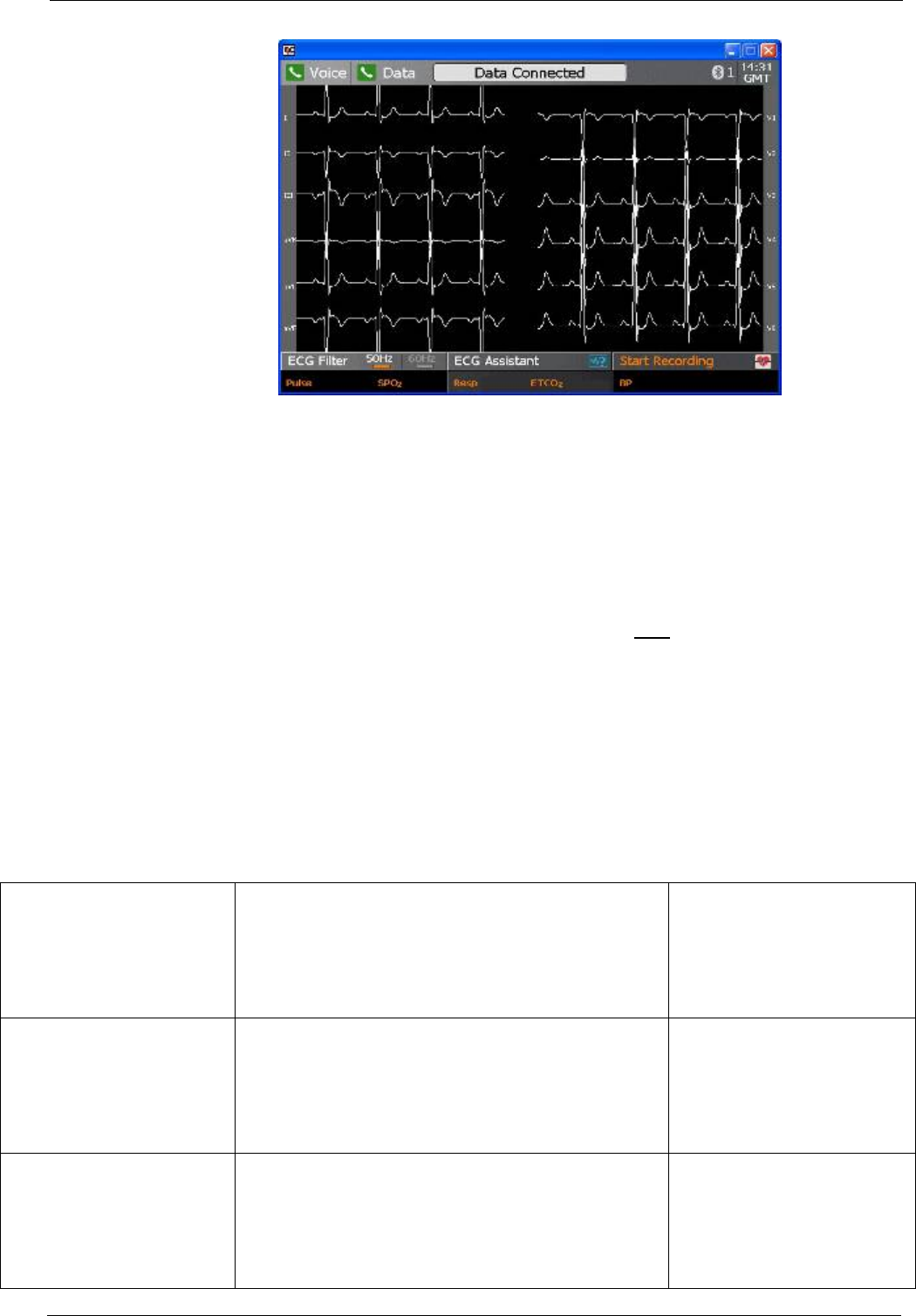
Tempus IC User/Operator Manual
You can see that the main part of the screen shows three sections. The right hand section
contains the thermometer readings setting which can be set to either °C or °F.
The left hand sections contain the settings for the filter frequency and ECG mode. The filter
frequency should be set to the mains supply frequency that is local to the Tempus IC or to
50Hz for use on-board aircraft. The ECG mode can be set to one of two types, either standard
or training mode.
If the Tempus IC is set into training mode (see section 10.3), then you will be able to set the
ECG into training mode. In this mode, the ECG (when activated) will produce artificial ECG
traces on the screen (labelled “DEMO”). The trainer mode is only designed for use when
training operators of the Tempus IC. It provides no purpose for real incidents and should not
be used. If the trainer mode is selected, the Tempus IC will revert to standard mode once it
has been turned off.
In the example shown, the data phone number is being edited, however the screen is the same
for all of the character based selections.
ECG lead-off LA Process to step user through checking ECG harness.
Button: RESTART ECG at
end of process.
Keypad keys (eg HOME) to
cancel this error and goto the
process associated with the
button.
ECG lead-off
V1, V2
Process to step user through checking ECG harness.
Button: RESTART ECG at
end of process.
Keypad keys (eg HOME) to
cancel this error and goto the
process associated with the
button.
ECG lead-off
V3, V4, V5, V6
Process to step user through checking ECG harness.
Button: RESTART ECG at
end of process.
Keypad keys (eg HOME) to
cancel this error and goto the
process associated with the
button.
Page 51 41-1001-00B
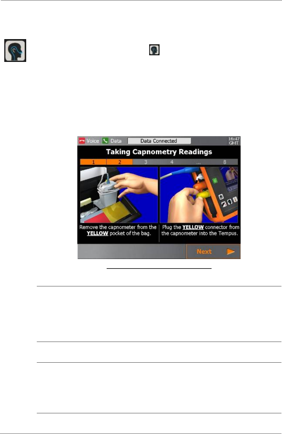
Tempus IC User/Operator Manual
8.5 Capnometer
To activate the Capnometer function, press button on the device
The first Capnometer help screen will appear.
Follow the instructions provided on the iAssist help process to activate Capnometer.
Example of the Capnometer Help Screen
WARNINGS
The Tempus IC is not intended for long term patient monitoring. There are no audible or
visible alarms.
The Tempus IC is not for apnoea detection. The Tempus IC has not been tested or
validated for use in apnoea detection.
CAUTION
Use of monitoring during continuous nebulised medication delivery will result in
damage to the Tempus IC which is not covered by the warranty. Disconnect the
capnometer sample line from the Tempus IC or switch off the Tempus IC during
medication delivery.
Page 52 41-1001-00B

Tempus IC User/Operator Manual
Notes
The capnometer requires regular calibration. A source of calibration gas is fitted within the
Tempus IC to enable the device to remain accurate and ready for use during its period of
intended use. The calibration gas can only be replaced by the manufacturer. If the Tempus IC
is not returned to RDT Ltd. for its regular preventative maintenance check, the capnometer will
eventually cease to operate.
The capnometer will perform self-calibrations as required when the Tempus IC is switched on
and the capnometer is operating. These operations may cause short delays (approximately 5-
10 seconds) in the display of measured results.
The capnometer is not for use in conjunction with breathing or anaesthetic systems.
8.5.1 Understanding the Capnometer Results
The Capnometer display has four data elements plus a status indicator. Measurements are
made continuously and updated in real time. Measurements are sent in real time to the
Response Centre provided that the data link is active.
Owing to the nature of the instrument, readings take a little time to first appear (up to 30
seconds), and a little longer to stabilise. This is perfectly normal.
The Respiration Rate section contains a bargraph and digital display of the patient's respiration
rate, in respirations per minute (Rpm).
• Note extreme respiration rates above 150 Rpm are outside the range of the bargraph
display but will be shown accurately on the digital display.
The ETCO2 reading indicates the end tidal mmHg reading of the breath, and displays the result
in bargraph and digital form.
The capnometer will take readings for 15 minutes and then stop. The capnometer can then be
re-activated by pressing the button.
The status bar beneath the results area will read “Press to stop” while the capnometer is
running. The capnometer will cease taking readings if the button is pressed while it is
running. To re-start the capnometer, simply press the button to bring the help screen up
and begin the process again.
.
Page 53 41-1001-00B
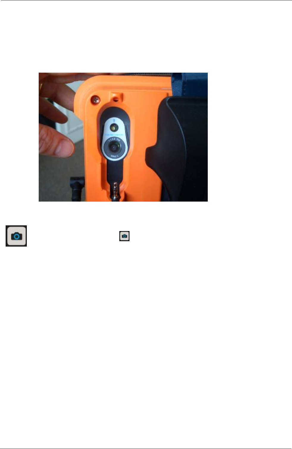
Tempus IC User/Operator Manual
8.6 Video Camera
When requested by the Response Centre, it is possible to capture and send still video images
using the camera built into the device. Video images are shown live on the Tempus IC screen
so that you can see what the camera is seeing. When you are happy with the displayed image,
you capture the picture and can then send it to the Response Centre (if you are not connected
the image will be stored for transmission later). Moving pictures cannot be sent to the
Response Centre.
To activate the Camera, press button on the device
The first Camera help screen will appear.
A video image from the camera will appear on the Tempus IC display in the position shown in the
following picture.
Follow the instructions provided on the iAssist help process to take a photo.
Page 54 41-1001-00B
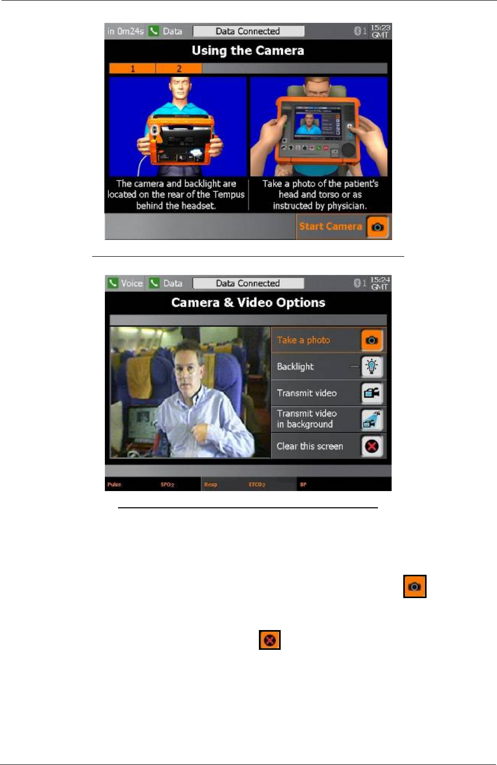
Tempus IC User/Operator Manual
Example of the Tempus IC Display Showing Location of Video Image
Example of the Tempus IC Display Showing Photo Image
Aim the video camera so that you get the picture you need on the screen (e.g. a close-up of the
patient).
When you are happy that the displayed image shows what you want, press on the touch
screen to freeze the image.
A countdown will appear on the screen before the picture is sent. To discard the image during the
countdown and take another picture, press , otherwise the picture will be sent when the
countdown reaches zero.
Page 55 41-1001-00B

Tempus IC User/Operator Manual
Page 56 41-1001-00B
8.6.1 Annotation of Video Images
Images transmitted from the Tempus IC can be altered using the software at the Response Centre.
The altered image can then be sent back to the Tempus IC to act as a support in the remote
diagnostic procedure i.e. the physician can send pictures back that can be used to confirm exactly
the issue being examined or discussed, thus avoiding the danger of misunderstanding verbal
descriptions.
Images can be amended using the following tools:
z
z
z
z
z
z
Zooming in and out
Addition of text
Addition of circles
Addition of lines and arrows
Addition of free-form lines
Selection of colours for added graphics
An example of an amended video image is shown above.
8.7 Interacting with the Response Centre
Although the Tempus IC may be used without connection to a Response Centre (i.e. if there is
a physician locally or if the unit is being used to collect data for later transmission), in most
incidents it is likely that a Response Centre will be contacted as the first priority after having
activated the device. Each Tempus IC device is pre-configured to dial automatically to a
specific Response Centre. This centre is staffed 24 hours a day, 365 days a year and staff will
always be waiting to receive your connection. If a connection cannot be established, you
should wait a short time and attempt to connect again.
The Tempus IC is designed to allow maximum ease of use for the operator (even extending to
partial remote control by the Response Centre if necessary) and also to transmit the medical
data to the Response Centre. It is the function of the Response Centre staff to help control the
situation, make an assessment based on the data received and to offer advice on the
appropriate steps to take.
When interacting with the Response Centre staff, please carry out all of their instructions to the
best of your ability. If anything is not obvious, do not hesitate to ask for clarification or further
guidance. Most incidents will begin with the Response Centre staff asking questions relating to
the nature of the incident. These questions may include such areas as:
• Nature of the patient e.g. name, sex, age, doctor’s details
• Nature of the problem e.g. perceived symptoms, known history (has the patient been
monitored using the Tempus IC before)
• Nature of the incident e.g. where the incident is taking place, who is responsible for the
remote location
Do not be concerned if any questions are asked that you do not have the answer to. The
questions are asked for the purpose of adding patient details in the Response Centre database
and to help aid diagnosis. If answers cannot be given at the time of asking, there will always
be opportunities to answer the questions once the incident is under control. In the event that
the incident is a serious one, the Response Centre will help to arrange for medical support to
be available either to the remote location or, if the incident occurs during a journey, at the point
where the journey will end.
When interacting with the Response centre staff, you should also realise that they will almost
always be operating in a different time zone to the one where the incident is taking place.
However, the time of the both the Tempus IC and the Tempus Monitoring Station (the
Response Centre hardware) are pre-set to operate on GMT (Greenwich Mean Time).
It is also likely that the Response Centre will ask for a video image to be transmitted as soon as
connection has been established. Videos transmitted to the Response Centre may be sent
back to the Tempus IC with markings or “annotations” placed onto the original image.

Tempus IC User/Operator Manual
Page 57 41-1001-00B
The Response Centre is continuously staffed by medical experts who will guide you in the use
of the Tempus IC. Once connection with the Response Centre is established, the operators
there will have exactly the same information on their screens as those displayed on the
Tempus IC. Should the Tempus IC display change e.g. if a new help screen is brought up, new
data is displayed or an error message appears, the Response Centre system will display
exactly the same information a few seconds later.
To give the Response Centre staff the best possible understanding of the nature of the
situation, verbal communication will also be needed. This is achieved using the Voicelink
earpiece speaker/microphone. In addition, the Response Centre staff can receive video
images from the Tempus IC via the data link. The Response Centre staff can receive still video
pictures from you so that they can further assess the condition of the patient. They can also
annotate the pictures you supply and send them back, for example to provide precise
instructions which may not be easy to convey via the spoken word.
If necessary, the Response Centre staff can operate the Tempus IC remotely, obtaining most of
the necessary readings and data via remote control. The operator at the Response Centre will
make you aware that they are activating a function of the device before or as they do it. It
should be noted that the Response Centre can only operate most functions of the device. The
thermometer must be operated locally to the Tempus IC and the camera must be positioned by
the Tempus IC operator (although the Response Centre can activate the camera remotely).
Ideally the Response Centre will only take control of the Tempus IC if the operator is having
difficulty with an operation.
8.8 Recording Data Off-line and Transmitting On-line
NOTE: The iAssist help processes on your Tempus IC may differ from this example iAssist help
process in the following sections. However the process always follows the same key
elements.
NOTE: Always ensure that you read the complete iAssist help process in order and do exactly what it
requires.
Although Tempus IC is generally intended to be used whilst connected from the remote
location to a Response Centre, Tempus IC can also be used without the telecoms connection
having been made. All the functions of Tempus IC operate normally if the telecoms
connections are not made, and data can be taken from a patient using all of the medical
devices that Tempus IC provides.
Naturally, if a connection has not been established, no data or photographs can be transmitted
and there will be no voice connection to the Response Centre operator. However, if Tempus IC
is used on a patient without a connection being made, the data is stored and can be
transmitted at a later date. There can be two advantages in this situation:
1. If a physician is present at the remote location, Tempus IC can be used and the data may
be used by the physician to help in the diagnosis and treatment of the patient.
2. Tempus IC can be used by the trained operator to take readings over a period of time
which can then be transmitted later to a Response Centre. This could be appropriate for
monitoring a patient after an initial incident has finished e.g. the Response Centre may
want to confirm that a patient’s condition has recovered and so wish readings to be taken
every 30 minutes (off line) and the data to be transmitted 4 hours later.
In the event that readings are taken off-line, all the normal requirements for using Tempus IC
must be followed. Once a connection has been established, Tempus IC will automatically
inform the Response Centre that there is stored data that can be transmitted. The Response
Centre operator will want to know the incident details of the recorded data (patient’s name, time
of the incident etc.). Since it may not be an appropriate time for you to give this information,
and since the download of the recorded incident may take some time (this will of course
depend on how long the previous incident was and how many ECGs or photographs were
taken), and potentially prevent you downloading data from the current incident, the Response
Centre operator will give you the option whether or not you wish to transmit the data
immediately. The Response Centre operator will give you the option of when to transmit the
information and will activate the download when it is appropriate to do so. There is no control
or mechanism that you have to operate to control this activity, it is all controlled for you by the
Response Centre.
There are two kinds of situations where data will be recorded off-line:

Tempus IC User/Operator Manual
Page 58 41-1001-00B
1. Tempus IC has been turned on, data has been recorded and Tempus IC then turned off
without a connection to the Response Centre being made. Tempus IC is then turned on at
a later date (probably for a different incident or patient) and the previously recorded data is
queued in the memory for transmission (if required).
2. Tempus IC is turned on, data has been recorded (e.g. recording taken for one hour) and
then the Tempus IC is connected to the Response Centre without being turned off i.e.
connection is established during the incident for the incident.
In the first case, the data recorded may be part of the same incident, or part of a different
incident but for the same patient, or for a new patient in a new incident. There can also be
more than one off-line recorded incident before a connection is established. Consequently the
Response Centre operator will need to know the details from the “historic” incidents when they
are downloaded.
In the second case, there can only be one set of data, and this can only be for the same patient
and incident that Tempus IC is attached to when connection to the Response Centre is
established.
Tempus IC is able to record as many off-line incidents as is required (until its capacity is full)
but it will delete the records of incidents once they are more than 7 days old. This means that
an off-line incident can only be transmitted within 7 days.
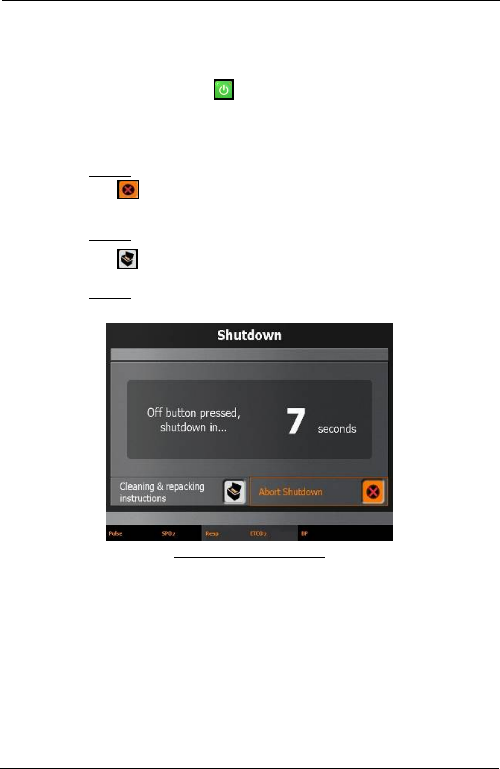
Tempus IC User/Operator Manual
8.9 Actions After Use – Turning the Tempus IC Off
Make sure that Tempus IC is not in use. Make sure that the voice and data links are not in use
and that the device is not being used to monitor a patient off-line.
Press-release the On/Off switch . The system will then bring up the dialog shown below
and give a 10 second countdown.
The lamp on the On/Off button will change from solid green to flashing orange.
When shutting down, the Tempus IC will show dialog containing a countdown timer from ten
seconds. The dialog reminds you to clean and repack Tempus IC using the icon provided.
Option A:
Press to stop the countdown and bring up the Instrument readings and results
screen.
Option B:
Press to stop the countdown and bring up the Cleaning & Repacking Menu iAssist
help process.
Option C:
Let the unit shutdown.
Example of the Shutdown Screen
Page 59 41-1001-00B

Tempus IC User/Operator Manual
9 After Using the Tempus IC
NOTE: The iAssist help processes on your Tempus IC may differ from this example iAssist help
process in the following sections. However the process always follows the same key
elements.
NOTE: Always ensure that you read the complete iAssist help process in order and do exactly what it
requires.
9.1 Cleaning the Tempus IC
It is necessary to clean the Tempus IC after use.
The screen may be cleaned using a proprietary screen cleaning wipe of the type used for other
LCD screens. Under no circumstances should any abrasive substance be applied to the
screen.
The Tempus IC instruments must be cleaned during the re-packing process.
If the Tempus IC is dirty it should be cleaned with to remove any cosmetic contamination. It
should be wiped down with a soft cloth, which may optionally be dampened with water and a
mild detergent solution.
The screen may be cleaned using a proprietary screen cleaning wipe of the type used for other
LCD screens. Under no circumstances should any abrasive substance be applied to the
screen.
The outer case of the Tempus IC should be cleaned to remove any cosmetic contamination. It
should be wiped down with a soft cloth, which may optionally be dampened with water and a
mild detergent solution.
9.2 Cleaning and Re-packing Help Screen
The user can get help at any time by pressing the button at any time. This will bring up the
Help Menu. There are multiple sequential menus covering different aspects of using the device
When the first Help Menu is on the screen, the next menu (Cleaning and Repacking Menu) can
be accessed by pressing the Next touchscreen button.
WARNING: The fluid contained within the wipes will cause temporary damage to the eye.
In the event of contact to the eye, wash thoroughly with water for 15 minutes.
Wash hands with soap and water after use
WARNING: Keep wipes away from open flame
NOTE: Wiped surfaces must be left wet for at least 1 minute.
NOTE: Wipes are not to be used as baby wipes.
NOTE: The wipes are not to be used to disinfect surfaces that have been soiled with
internal bodily fluids (other than sweat). If such soiling has occurred, the item
should not be used and should be returned to RDT.
Page 60 41-1001-00B
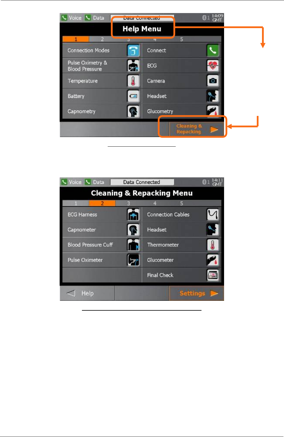
Tempus IC User/Operator Manual
Page 61 41-1001-00B
Example of the Help Menu
From the Help
Menu, press
the Next
button to bring
up the
Cleaning and
Repacking
Menu
The user can press any one of the following icons on the touch screen to get help cleaning and
repacking the device.
Example of the Cleaning and Repacking Menu
The user can move backwards and forwards through the iAssist help processes by pressing the
Next and Previous touchscreen buttons.
It is important that you follow all the applicable repacking steps starting with ECG Harness and
finishing with Final Check. It is important that you always perform the Final Check process.
Suitable cleaning wipes labelled "Alcowipe" are provided within the Tempus IC. The help
screen shows the location of the wipes and the user must follow the instructions provided on
the iAssist help process to clean and repack the device.
9.2.1 Cleaning the Tempus and its Accessories:
Use a cloth dampened with isopropyl alcohol 70%, a 10% aqueous solution of sodium
hypochlorite (bleach), a 2% gluteraldehyde solution, ammonia, mild soap or disinfectant spray
cleaner such as Steris Coverage® Spray HB.

Tempus IC User/Operator Manual
Page 62 41-1001-00B
Wipe down with a clean water-dampened cloth to rinse and dry before use. Make certain that
the sensor windows are clean and dry before reuse.
9.3 Single-use Devices
The following accessories are single-use devices and must be discarded after use. No
particular precautions are required when disposing of these items provided that they are not
contaminated with bodily fluids. In case of such contamination, the items should be disposed
of in accordance with local regulations.
Part Description:
• AlcoWipes
• Nail Varnish Wipes
• Vinyl Gloves
• Thermometer Covers
• Glucometer Lancets
• Glucometer Strips

Tempus IC User/Operator Manual
Page 63 41-1001-00B
10 Maintenance, Servicing and Troubleshooting
NOTE: The iAssist help processes on your Tempus IC may differ from this example iAssist help
process in the following sections. However the process always follows the same key
elements.
NOTE: Always ensure that you read the complete iAssist help process in order and do exactly what it
requires.
10.1 General
The Tempus IC is designed to be as maintenance-free as possible. The only user-replaceable
and user-serviceable parts in the Tempus IC are those listed in this section of the manual.
NOTE: If the Tempus IC is no longer serviceable and is beyond repair, it may be
scrapped. Scrapping the device and its accessories must be performed in
compliance with applicable local regulations. It should be noted that special
conditions may apply to the rechargeable battery if it is required to be
scrapped. The battery should be discharged before scrapping and should
not be crushed or incinerated.
10.2 Battery Management
10.2.1 The Battery
The Tempus IC is provided with a rechargeable battery. In normal usage, the rechargeable
battery provides power for at least 4 hours' continuous* use when fully charged.
Every battery is provided with an integral battery life indicator which is also visible through the
front panel of the case.
The battery life should be monitored periodically over time when the device is in storage and
also before and after use.
NOTE: RDT recommends that the battery charge status should be checked once a year and
recharged if necessary. RDT also recommends that the battery be completely discharged and
recharged once a year.
NOTE: The User should remember that battery life of older batteries will not be the same as
new batteries.
By monitoring the remaining battery life, situations where the battery is too weak to power the
Tempus IC for the duration of an incident can be avoided. If the battery strength indicator
shows less than 20% power remaining, you should change the battery if possible to ensure that
there is adequate power for the patient incident.
However, using the battery down to the point where it is completely empty will not cause any
hazards or damage to the system.
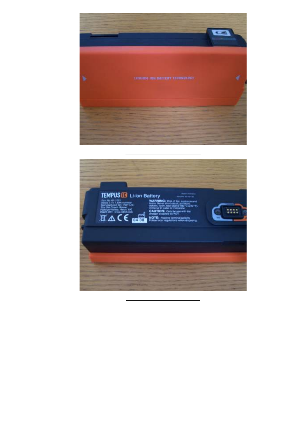
Tempus IC User/Operator Manual
Example of the Battery Front
Example of the Battery Rear
*Assessment of use is based on projections of reasonable device usage within a patient incident made by RDT.
10.2.2 Connecting the Battery
It is necessary to install the supplied battery into the Tempus IC before it will operate. Section
Error! Reference source not found. describes this procedure in detail.
10.2.3 Charging the Battery
It is necessary to ensure that the battery is fully charged before the Tempus IC is put into
service.
NOTE: Batteries self discharge over time and lose charge capacity over time (see Battery
Specification) Refer to the Tempus IC Battery Charger manual (part number 41-10XX) for a
detailed description of how to charge the battery.
Page 64 41-1001-00B
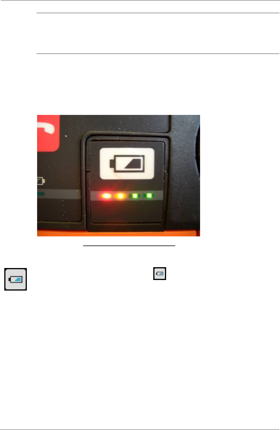
Tempus IC User/Operator Manual
WARNING
BATTERY CHARGING MUST ONLY BE CARRIED OUT USING THE BATTERY CHARGER
SUPPLIED FOR THAT PURPOSE BY RDT.
10.2.4 Understanding the Battery Life Indicator
Tempus IC battery is provided with a battery life indicator which gives an indication of the
amount of charge left in the battery in three grades relative to full charge. The battery life
indicator is also accessible from the front panel of Tempus IC. This battery life indicator is
located to the left of the power switch.
Example of the Battery Life Indicator
The following description applies both to the battery life indicator on the battery and the front panel
indicator.
To activate the battery life indicator, press the button. One of the different coloured lights will
illuminate:
• Green light is on (with or without any other light) = 100%-71% of full charge (the battery is
fresh and will give at least 4 hours of run time)
• Yellow light is on (but green is not) = 70%-21% of full charge
• Red = 20%-6% of full charge (the battery is nearly exhausted)
• Red flashing = less than 5% of battery charge remaining
• No lights = battery completely exhausted.
The battery life indicator should only be regarded as a guide to the battery condition.
10.2.5 The Tempus IC Battery
The Tempus IC contains a removable, rechargeable battery.
Page 65 41-1001-00B
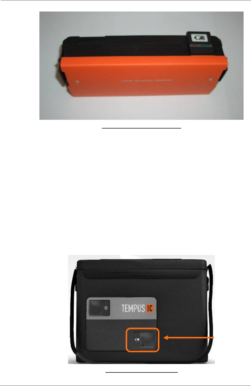
Tempus IC User/Operator Manual
Example of the Tempus IC Battery
The battery is fitted in the base of the Tempus IC. The charge state of the battery can be
obtained by pressing the button on the front.
The battery is provided with 4 charge state LEDs. Pressing the button will light one or more
lights. Each light corresponds to 25% of the charge state of the battery in the order (from
highest to lowest):
Green – 76-100%
Green – 51-75%
Amber – 26-50%
Red – 1-25%
NOTE: If the red light is flashing the battery has 10% or less charge remaining.
These will light cumulatively when the battery button is pressed i.e. only the red light will light if
the charge state is 1-25% after which the amber light will light as well.
10.2.6 Checking the Charge State of the Battery
The charge state of the battery can be checked while the Tempus IC is in its storage Bag.
Example of the Tempus IC Bag
Pressing the battery button behind the window will light one to four coloured lights.
Window to check
the battery
Page 66 41-1001-00B
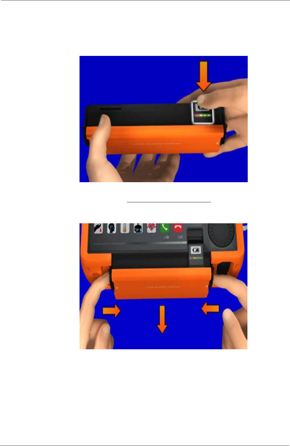
Tempus IC User/Operator Manual
The Tempus IC does not need to be removed or turned on to check the battery.
10.2.7 Removing the Battery from the Tempus IC
To replace the battery:
1 First check the replacement battery has sufficient charge by checking its indicator.
Example of the Battery Indicator
2 Next, ensure the Tempus is switched off. Then remove the battery by squeezing the
two latches inwards, then pull the battery away.
WARNING: Do not short-circuit the terminals of any battery. A short circuit can occur if the
battery terminals come into contact with any metal or other electrically
conductive object. The battery may be irreversibly damaged if it is short-
circuited.
NOTE: Before removing the battery you must switch off the Tempus IC by pressing
and holding the power button for two seconds.
NOTE: Remember that the battery cannot be removed until the red lamp on the front
panel has gone out.
3 Slide the new battery all the way into the Tempus until it clicks into place on both sides.
Page 67 41-1001-00B
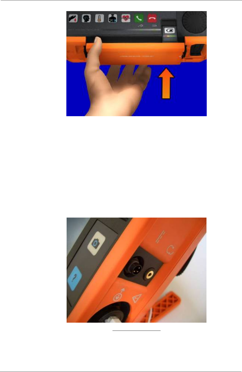
Tempus IC User/Operator Manual
10.2.8 Charging the Battery
The battery can be charged either when it is fitted to the Tempus IC or when it is removed from
the separate battery charger.
10.2.8.1 Charging the battery from the Tempus IC
1. When fitted to the Tempus IC, the battery can be charged by connecting the power
supply (part number 01-1017) to the 3 pin connector on the right hand side of the
Tempus.
2. When the power supply is attached to the Tempus IC, the green power light on the
Tempus IC front panel will turn on.
3. If a battery is attached the green charge light will flash. The lights on the battery will
light solidly up to the charge state of the battery at the time.
NOTE: Batteries cannot be charged on board aircraft but may be charged in land or sea
based locations (where no other restrictions apply e.g. in hazardous locations).
The Power Connector
Page 68 41-1001-00B
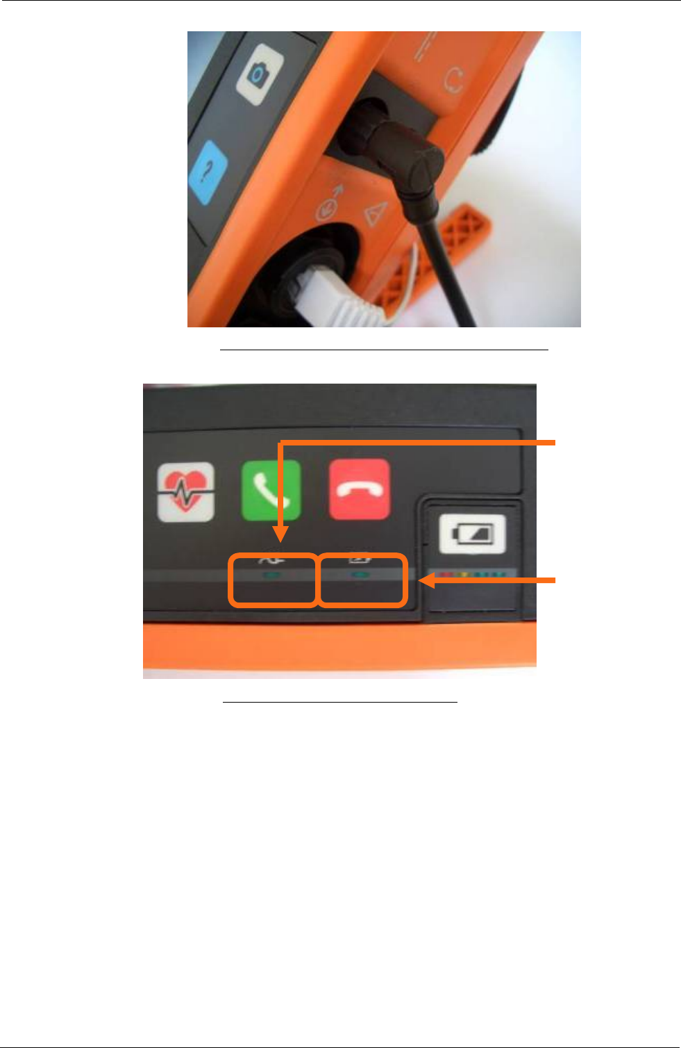
Tempus IC User/Operator Manual
The PSU Plug Attached to the Tempus IC Connector
Battery
Charge Light
Power Light
The Power Light and the Charge Light
NOTE: Power supply is rated 110-240V 50-60Hz 1.5A.
NOTE: Charge times of the battery will vary depending on the how the Tempus IC is being
used. If the Tempus is switched off charging will be faster than if the Tempus is on
and all features are being used.
NOTE: Charging a completely empty battery will take 6 hours when the Tempus IC is
switched off.
10.2.8.2 Charging the battery directly from the Battery Charger IC
When the battery is separate from the Tempus IC, the battery may be charged by connecting it
to the battery charger (part number 01-1012). To attach the charger to the battery, the clip
must be firmly pressed onto the connections of the battery. Note that the clip of the charger
can only be connected to the battery in one way.
Page 69 41-1001-00B

Tempus IC User/Operator Manual
The Battery Connector Attached to the Battery
1. Clip the charger to the battery (the clip only attaches in one way).
2. Attach the charger to the main supply.
3. The charger’s LED will light orange (for approximately 0-85% charge), change to yellow
during charging (at approximately 86-100% charge) and will turn green when finished. If the
battery is only partially discharged then the LED may start on yellow.
NOTE: Battery charger is rated at 100-240V 50-60Hz 0.9A.
NOTE: Recharging the battery takes up to 6 hours for a fully discharged battery.
10.2.9 Tempus IC Battery Shelf Life
10.2.9.1 Shelf Life of Batteries Stored as Spares
A new and fully charged battery retains approximately 70% of its charge after 12 months in
storage detached from the Tempus IC. This equates to approximately 4 hours of use.
NOTE: RDT recommends that the battery is topped up annually.
NOTE: Specifications for the battery are based on a new, fully charged battery. Shelf life
ratings are based on new, fully charged packs which are stored separately from the
device at 20°C. Shelf life performance will decrease over time and will be lower if
the battery is stored in higher or lower ambient temperatures.
10.2.9.2 Shelf Life of Batteries Stored in the Tempus IC
A new and fully charged battery retains approximately 70% of its charge after 12 months in
storage attached to the Tempus IC. This equates to approximately 4 hours of use.
NOTE: RDT recommends that the battery is topped up annually.
NOTE: Specifications for the battery are based on a new, fully charged battery. Shelf life
ratings are based on new, fully charged packs which are stored separately from the
device at 20°C. Shelf life performance will decrease over time and will be lower if
the battery is stored in higher or lower ambient temperatures.
10.3 Other Tempus IC Batteries
10.3.1 Wireless Headset Battery
The headset contains a rechargeable battery. The battery of the headset is not user-
replaceable and does not require user intervention. In the unlikely event that the headset’s
battery becomes completely exhausted and can no longer hold charge, a replacement headset
can be purchased.
Page 70 41-1001-00B

Tempus IC User/Operator Manual
Page 71 41-1001-00B
10.3.2 Disposal of Batteries
Dispose of batteries in accordance with the applicable local regulations (these can vary from
country to country).
NOTE: In most countries, the trashing of used batteries is forbidden and the end-users are
invited to dispose them properly, eventually through not-for-profit profit
organisations, mandated by local governments or organised on a voluntary basis by
professionals.
10.4 Troubleshooting
Occasionally, problems may occur with the Tempus IC. Operator error, sensor problems or a
failure within the Tempus IC could cause these problems. In most instances, the Tempus IC
will display an error message on the screen. This section describes the possible error
messages and what they mean.
All of the error messages take the form of a window which appears in the middle of the screen.
The window contains the following text:
• a title which identifies the sensor or system which is having trouble
• a description of the problem
• the effect that the error will have on the performance of the Tempus
• which button to press to clear the error message off the screen.
CAUTION: In the event that the Tempus IC displays an error that is not described within
this manual e.g. Windows applications errors, turn the Tempus IC off and then
on again. This should clear the error and allow normal operation to resume.
Do not continue to use the device if such an error is displayed. If symptoms
persist, please contact RDT
The following tables list all the error messages which the Tempus IC may generate under
abnormal conditions.
10.5 Audio & Dialog Errors
The audible alerts are on are played every 5 seconds while an error is being
displayed, until the error is cleared
The different error dialog types are shown below.
10.5.1 Error Dialog - Type 1
Error Dialog - Type 1
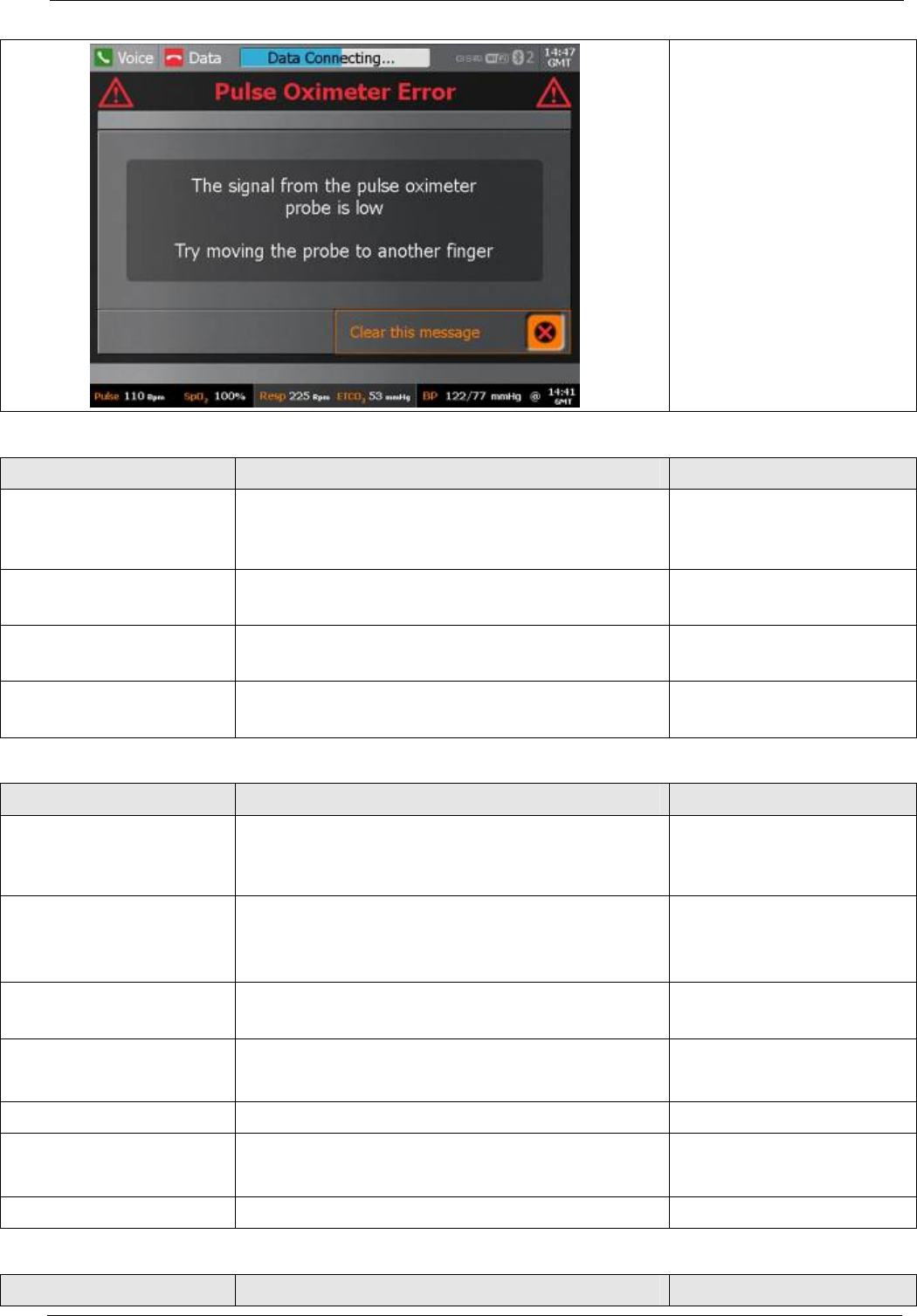
Tempus IC User/Operator Manual
• Example of Error
Message
10.5.1.1 Attention – Pulse Oximeter
Audio Message Text Message Button(s)
Pulse Oximeter Error The signal from the pulse oximeter probe is
low
Try moving the probe to another finger
Clear this message
Pulse Oximeter Error There is a fault with the Pulse Oximeter
It has been disabled
Clear this message
Blood Pressure Error There is a fault with the Blood Pressure
It has been disabled
Clear this message
Pulse Oximeter Cable
Error
Please connect the pulse Oximeter before
shutdown
Clear this message
10.5.1.2 Attention - Capnometer
Audio Message Text Message Button(s)
Capnometer Error Capnometer is blocked.
Disconnect and reconnect the cannula.
Check the cannula for blockages, or kinks.
Clear this message
Capnometer Error The cannula is not plugged into the
capnometer.
Repeat step 7 of the instructions.
Return to instruction
Capnometer Error There is a fault with the Capnometer
It has been disabled
Clear this message
Capnometer Error Capnometer is not plugged in.
Repeat step 2 of the instructions.
Return to instruction
Capnometer Error Capnometer sensor error or range error. Clear this message
Capnometer Error Capnometer zero required.
Sop and restart Capnometer.
Clear this message
Capnometer Error No Capnometer is available on this unit. Clear this message
10.5.1.3 Attention - ECG
Audio Message Text Message Button(s)
Page 72 41-1001-00B

Tempus IC User/Operator Manual
Page 73 41-1001-00B
ECG Error An error occurred with the ECG
Please restart the ECG and try again
Clear this message
ECG Error There is a fault with the ECG
It has been disabled
Clear this message
ECG Leads Error ECG leads off or cable not plugged in. Clear this message
10.5.1.4 Attention – Low Battery
Audio Message Text Message Button(s)
Battery Warning There is approximately 60 minutes of battery
remaining
Clear this message
Battery Warning There is less than 30 minutes of battery
remaining.
Tempus will perform a managed switch-off
within 30 minutes.
The battery should be changed.
Clear this message
10.5.1.5 Attention – Battery
Audio Message Text Message Button(s)
Battery Recharge Error The battery requires recharging.
Complete ops log or recharge battery.
Clear this message
10.5.1.6 Attention – Connection
Audio Message Text Message Button(s)
Connection In
Progress Error
Tempus is already trying to make a
connection
Clear this message
Connection Is Active
Error
Tempus is already connected. Clear this message
Connection Error The Tempus is connected so the mode
cannot be changed.
Clear this message
Connection Error You have not completed the data connection
process. Are you sure this is what you want
to do?
Clear this message
10.5.1.7 Attention – Data Centre
Audio Message Text Message Button(s)
Error Response centre is not responding Clear this message
10.5.1.8 Attention – Headset
Audio Message Text Message Button(s)
Headset Not On The headset has not connected to the
Tempus.
Repeat step 3 of the instructions.
Return to instruction
Headset Not Replaced Headset should be replaced before
shutdown
Clear this message
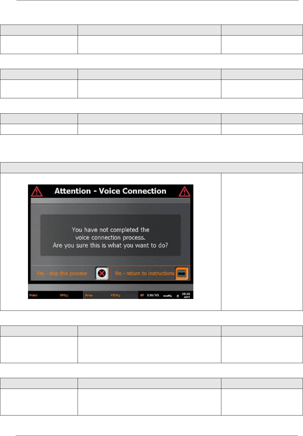
Tempus IC User/Operator Manual
10.5.1.9 Attention – Installation Modes Warning
Audio Message Text Message Button(s)
Installation Modes
Warning
Engineering dept personnel only for
installation on a different aircraft.
Clear this message
10.5.1.10 Attention – Video Bandwith
Audio Message Text Message Button(s)
Video Bandwidth Error No datalink connected or bandwidth
insufficient for video.
Clear this message
10.5.1.11 Attention – Socket
Audio Message Text Message Button(s)
Socket Error The connection could not be established. Clear this message
10.5.2 Error Dialog - Type 2
Error Dialog - Type 2
• Example of Error
Message
• Left button: ‘Yes - skip
this process’, allows
user to exit the
connection process;
and go to the state
requested by the key
that was pressed.
• Right button: ‘No -
return to instructions’ –
returns to connection
process exactly where
it was before the key
press that triggered the
error.
10.5.2.1 Attention – Connection
Audio Message Text Message Button(s)
Connection Error You have not completed the data connection
process. Are you sure this is what you want
to do?
No - return to instructions
Yes - skip this process
10.5.2.2 Attention – Voice Connection
Audio Message Text Message Button(s)
Voice Connection
Error
You have not completed the voice
connection process. Are you sure this is
what you want to do?
No - return to instructions
Yes - skip this process
Page 74 41-1001-00B

Tempus IC User/Operator Manual
Page 75 41-1001-00B
10.5.2.3 Attention – Trainer Mode
Audio Message Text Message Button(s)
Trainer Mode Warning This unit is set to restart in training mode
and so will not connect to a response centre.
No - return to instructions
Yes - skip this process
10.5.2.4 Attention – ECG
Audio Message Text Message Button(s)
EGC Lead-off ECG not plugged in or lead is not in good
skin contact.
No - return to instructions
Yes - skip this process
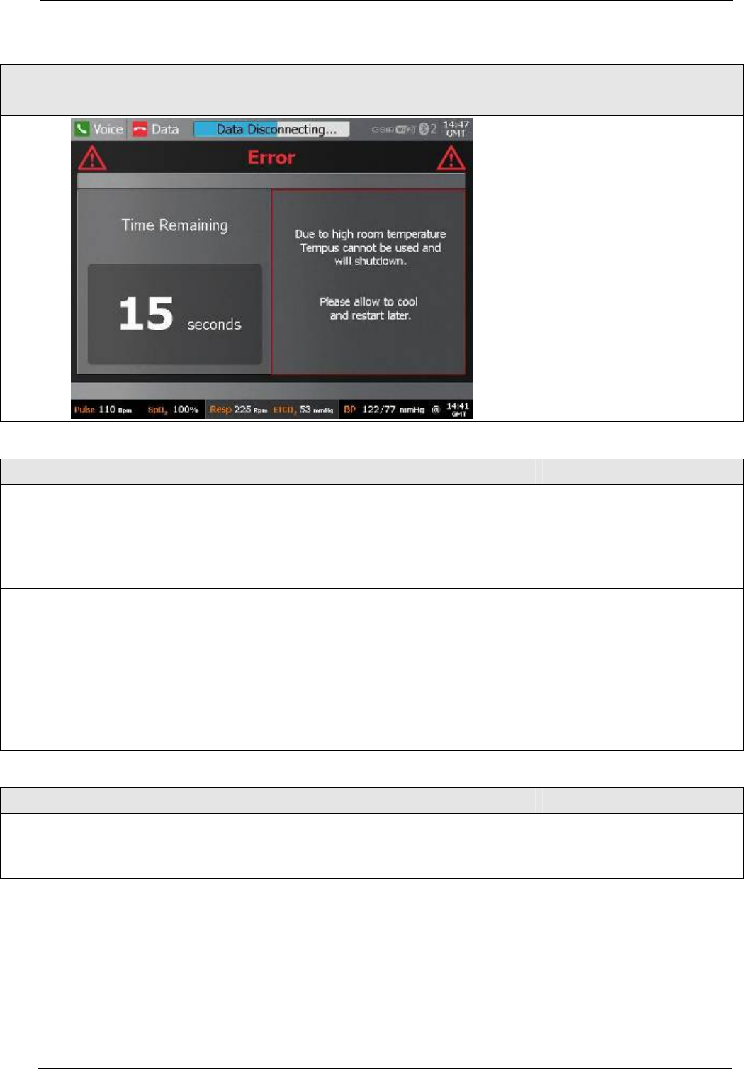
Tempus IC User/Operator Manual
10.5.3 Error Dialog - Type 3a
Error Dialog - Type 3a
(shutdown and wireless communication warnings)
• Left dialog shows the
‘Time Remaining’
which is counting
down in ‘seconds’
• Right dialog shows
the connection error
dialog
10.5.3.1 Error
Audio Message Text Message Button(s)
Shutdown Warning A fault has occurred. To clear the problem
Tempus will switch off. Please switch back
on once the shutdown is complete. If the
problem persists please contact your
supplier.
None
Shutdown Warning Due to low room temperature Tempus
cannot be used and will shutdown. Please
allow to warm and restart later.
None
Shutdown Warning Due to high room temperature Tempus
cannot be used and will shutdown. Please
allow to cool and restart later.
None
10.5.3.2 Battery Empty
Audio Message Text Message Button(s)
Shutdown Warning The battery is empty. Tempus will perform a
managed switch-off. The battery should be
changed.
None
Page 76 41-1001-00B
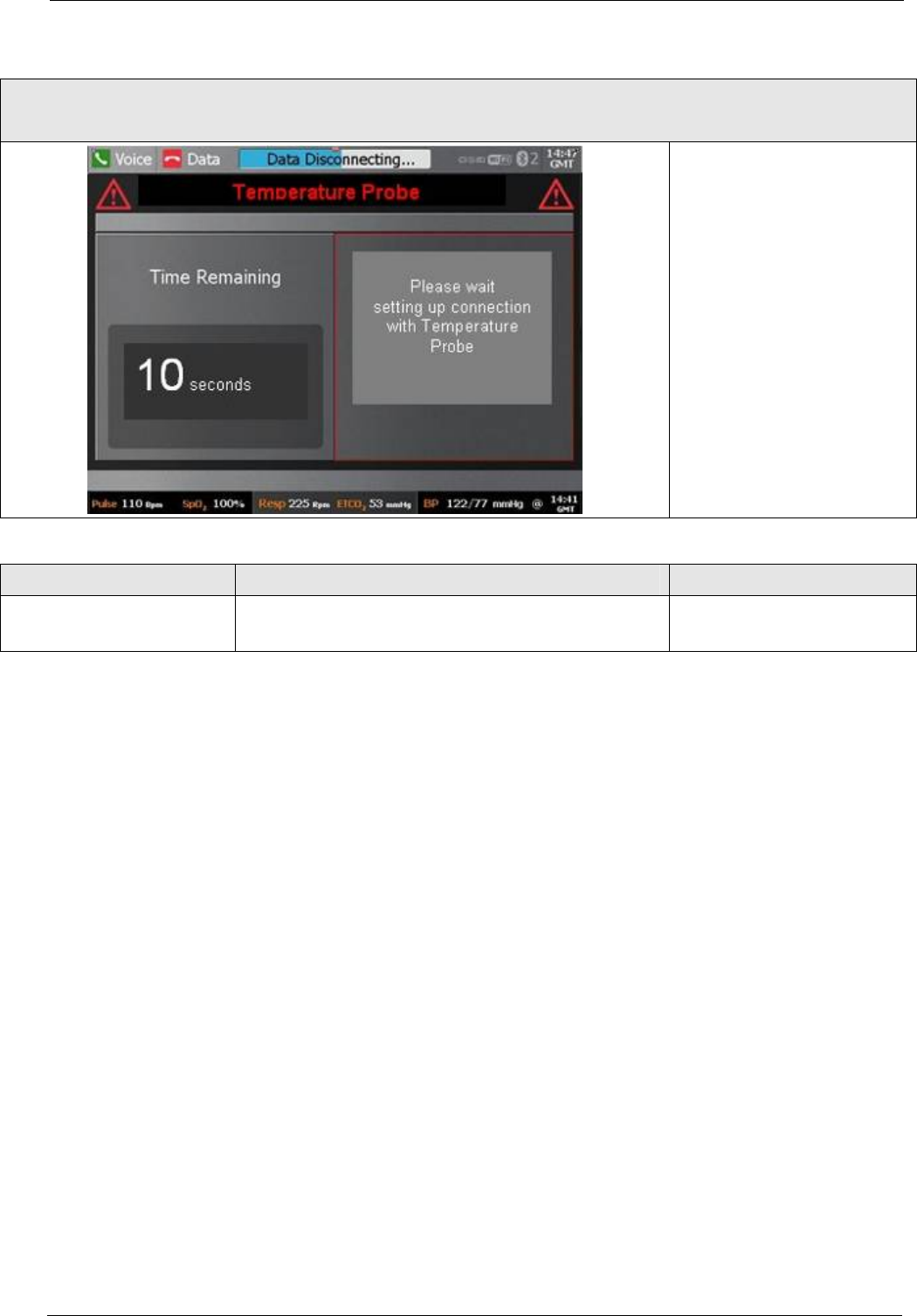
Tempus IC User/Operator Manual
10.5.4 Error Dialog - Type 3b
Error Dialog - Type 3b
(shutdown and wireless communication warnings)
• Left dialog shows the
‘Time Remaining’
which is counting
down in ‘seconds’
• Right dialog shows
the connection error
dialog
10.5.4.1 Tempus is Linking to the Headset
Audio Message Text Message Button(s)
Headset Connected Please wait, setting up connection to the
headset.
None
Page 77 41-1001-00B
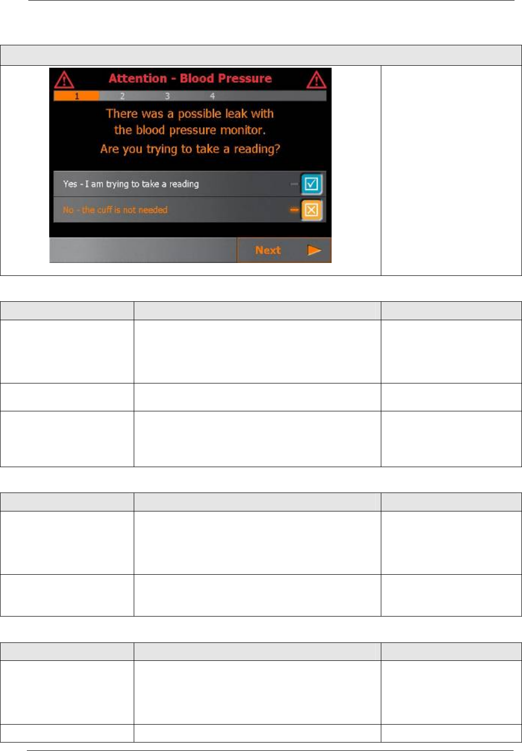
Tempus IC User/Operator Manual
10.5.5 Process Errors
• If ‘No - the cuff is not
needed’ is selected
when ‘Next’ is pressed
the error is cleared: no
further steps.
• If ‘Yes - I am trying to
take a reading’ is
selected when ‘Next’ is
pressed proceed
through help steps.
• ‘Next’ step to help user
to check the cuff.
• Final step button:
“Restart”, this button
starts BP.
10.5.5.1 BP Cuff Leak Error
Audio Message Text Message Button(s)
Attention - Blood
Pressure
There was a possible leak with the blood
pressure monitor.
Are you trying to take a reading?
Yes - I am trying to take
a reading + Next
No - the cuff is not
needed + Next
Attention - Blood
Pressure
Check that the cuff is properly attached Next
Attention - Blood
Pressure
Check that the cuff is firmly wound
around the patient's arm.
Tell patient to sit still, relax and not speak
during the reading.
Next
10.5.5.2 BP Artefact Error
Audio Message Text Message Button(s)
Attention - Blood
Pressure
The blood pressure monitor has detected
movement.
Are you trying to take a reading?
Yes - I am trying to take
a reading + Next
No - the cuff is not
needed + Next
Attention - Blood
Pressure
Attention - Blood Pressure
Tell patient to sit still, relax and not speak
during the reading.
Next
10.5.5.3 BP Weak Signal Error
Audio Message Text Message Button(s)
Attention - Blood
Pressure
There was a weak signal from the blood
pressure monitor.
Are you trying to take a reading?
Yes - I am trying to take
a reading + Next
No - the cuff is not
needed + Next
Attention - Blood Check the hose connector is pushed firmly Next
Page 78 41-1001-00B

Tempus IC User/Operator Manual
Page 79 41-1001-00B
Pressure in.
Attention - Blood
Pressure
Check the hose for kinks and knots.
Check the cuff has been correctly
placed in the centre of the arm
and the hose is not twisted.
Next
Attention - Blood
Pressure
Check that the cuff is firmly wound
around the patient's arm.
Tell patient to sit still, relax and not speak
during the reading.
Next
10.5.5.4 BP Over Pressure Error
Audio Message Text Message Button(s)
Attention - Blood
Pressure
There was an over-pressure signal from the
blood pressure monitor.
Are you trying to take a reading?
Yes - I am trying to take
a reading
No - the cuff is not
needed + Next
Attention - Blood
Pressure
There was an over-pressure signal from the
blood pressure monitor.
Are you trying to take a reading?
Yes - the cuff is in use +
Next
No (returns to the
previous help step)
Attention - Blood
Pressure
Check the hose connector is pushed firmly
in.
Next
Attention - Blood
Pressure
Check the cuff has been correctly placed in
the centre of the arm above the elbow.
Make sure that the patient’s arm is not bent
and is kept still.
Next
Attention - Blood
Pressure
Check the cuff or the hose are not against a
vibrating surface and the hose is not being
moved.
Tell patient to sit still, relax and not speak
during the reading.
Next
10.5.5.5 Pulse Oximeter - Finger Not Sensor Error
Audio Message Text Message Button(s)
Attention - Pulse
Oximeter
There is no signal from the pulse oximeter
sensor.
Are you trying to take a reading?
Yes - I am trying to take
a reading + Next
No + Next
Attention - Pulse
Oximeter
Check the patient's RIGHT hand finger is
fully inserted into the sensor. If necessary
move the sensor to another finger.
Next
10.5.5.6 Pulse Oximeter - Unplugged Error
Audio Message Text Message Button(s)
Attention - Pulse
Oximeter
Attention - Pulse Oximeter Sensor
The pulse oximeter sensor is not plugged in.
Plug the sensor back in.
OK (process is to plug
sensor back in)

Tempus IC User/Operator Manual
Page 80 41-1001-00B
10.5.5.7 ECG lead-off (All Off)
Text Message Text Message Button(s)
Poor Contact-All or
Some Electrodes
Make sure the BLUE plug is firmly pushed
all the way in to the BLUE socket.
Next + Restart ECG
Poor Contact-All or
Some Electrodes
Remove the bent electrode and generously
spray it (GREY side).
Next + Restart ECG
Poor Contact-All or
Some Electrodes
Replace bent electrode under LEFT hip
waistline between skin and clothes.
Electrode (GREY side) MUST touch skin.
Next + Restart ECG
Poor Contact-All or
Some Electrodes
Check that the RED lead is pressed onto the
strap on the patient's RIGHT wrist.
Make sure the strap is tight on the patient's
RIGHT wrist. Re-spray the wrist under the
strap.
Next + Restart ECG
Poor Contact-All or
Some Electrodes
Pull the harness forward, generously spray
the GREY electrode at the bottom.
Next + Restart ECG
Poor Contact-All or
Some Electrodes
Tell the patient they must be completely
relaxed for the recording. Ask the patient to
sit still and not to move while you are
recording the ECG.
REMEMBER to wait for the trace to stabilise
before starting the recording.
Next + Restart ECG
10.5.5.8 ECG lead-off (Left Wrist Off)
Text Message Text Message Button(s)
Poor Contact - Left
Wrist Electrode
Check that the YELLOW lead is pressed
onto the strap on the patient's LEFT wrist.
Make sure the strap is tight on the patient's
LEFT wrist.
Respray the wrist under the strap.
Next + Restart ECG
Poor Contact- Left
Wrist Electrode
Tell the patient they must be completely
relaxed for the recording.
Ask the patient to sit still and not to move
while you are recording the ECG.
REMEMBER to wait for the trace to stabilise
before starting the recording.
Next + Restart ECG
10.5.5.9 ECG lead-off (V1-V2)
Text Message Text Message Button(s)
Poor Contact - Red or
Yellow Electrode
Check the harness is on the centre of the
patient's chest and the strap is positioned
as shown.
Next + Restart ECG
Poor Contact - Red or
Yellow Electrode
Check the strap is tight, the harness must
NOT be loose.
To tighten the strap, hold the buckle and
pull the strap through.
Next + Restart ECG
Poor Contact - Red or Ensure the RED and YELLOW electrodes Next + Restart ECG

Tempus IC User/Operator Manual
Page 81 41-1001-00B
Yellow Electrode are touching the skin.
If necessary, gently bend them in or out to
ensure contact with the patient's skin.
Poor Contact - Red or
Yellow Electrode
Generously spray the RED and YELLOW
electrodes.
If the patient is hairy, spray the chest
directly where the electrodes contact the
skin.
Next + Restart ECG
Poor Contact - Red or
Yellow Electrode
Tell the patient they must be completely
relaxed for the recording. Ask the patient to
sit still and not to move while you are
recording the ECG.
REMEMBER to wait for the trace to stabilise
before starting the recording.
Next + Restart ECG
10.5.5.10 ECG lead-off (V3, V4, V5, V6)
Text Message Text Message Button(s)
Poor Contact - Green,
Brown, Black or Purple
Electrode
Check the strap is tight, the harness must
NOT be loose.
To tighten the strap, hold the buckle and pull
the strap through.
Next + Restart ECG
Poor Contact - Green,
Brown, Black or Purple
Electrode
Check the GREEN, BROWN, BLACK and
PURPLE electrodes are touching the skin
and that the strap is not twisted.
Next + Restart ECG
Poor Contact - Green,
Brown, Black or Purple
Electrode
Generously spray the GREEN, BROWN,
BLACK and PURPLE electrodes.
If the patient is hairy, spray the chest directly
where the electrodes contact the skin.
Next + Restart ECG
Poor Contact - Green,
Brown, Black or Purple
Electrode
Tell the patient they must be completely
relaxed for the recording.
Ask the patient to sit still and not to move
while you are recording the ECG.
REMEMBER to wait for the trace to stabilise
before starting the recording.
Next + Restart ECG
10.5.5.11 Voice Link Error
Text Message Text Message Button(s)
Attention - Voice
Connection Error
The Tempus is connected correctly but a
communications link is not available at this
time.
Next
Attention - Voice
Connection Error
IMPORTANT - Select one of the following
options
• Wait 10 minutes and then redial the
voice link
• Redial the voice link immediately
Next
Attention - Voice
Connection Error
Continue managing the patient and taking
readings.
Remember to restart the connection process
in 10 minutes.
If this error is displayed persistently, ask the
OK

Tempus IC User/Operator Manual
Page 82 41-1001-00B
Captain to log onto another GES.
10.5.5.12 Shutdown Error
Audio Message Text Message Button(s)
None Important Information
Inform maintenance or record in the log the
following:
Battery charge below 75%, 50% or
25%
Repack kit required
Capnometer cannula required
Device fault reported
Confirmed
Attention - Headset Headset should be replaced before
shutdown
Clear this message
None Countdown starts at 10s, counts down in
seconds Powers off when countdown
reaches 0s.
If user requests Cleaning and Repacking
Instructions the power-down is cancelled
and help screen for cleaning and repacking
displayed.
Cleaning and repacking
Instructions (this
cancels the shut down
and returns to repacking
menu).
or
Abort shutdown this
cancels the shutdown).
Not able to connect to a network
Not plugged in
Cant see wifi access point
Can’t see GSM
Try new mode
Reboot unit
Can make a connection but not able to connect
Try again
New mode
Can’t get through your network, can

Tempus IC User/Operator Manual
Page 83 41-1001-00B
(network error)
10.5.6 Mode Specific Error Processes
The error processes below are mode specific and the principle for each error is the same, there
are steps to correct the fault.
At the end of the error process in some cases the function required is different. For example on
data errors the process may end with the user clearing the error without a re-try; in other modes
the process may end with a re-try/re-dial of the connection.
Title Process Notes (for XML configuration) Button(s)
Datalink Error These processes may have 2, 3, 4, 5, or 6
steps defined in the XML configuration file.
The final screen in the process will have a
default key. This key may have 1 of 3
functions:
• Dial data
• Clear this message
• Backup mode
Variations depend on the mode, examples
are:
• Landline datalink error 4 steps
Dual POTS datalink error 10 steps
As standard help
process with
PREVIOUS, NEXT and
Final key defined in
XML files.
The XML file needs to
allow for 2 different keys
at the end of this
process. In some cases
we tell the user to Dial
Data and in some cases
want to just clear the
screen.
Voicelink Error These processes may have 2, 3, 4, 5, or 6
steps defined in the XML configuration file.
The last screen in the process will have a
default key. This key may have 1 of 2
As standard help
process with
PREVIOUS, NEXT and
Final key defined in
XML files.

Tempus IC User/Operator Manual
Page 84 41-1001-00B
functions:
• Dial voice
• Clear this message
The XML file needs to
allow for 2 different keys
at the end of this
process. In some cases
we tell the user to Dial
Voice and in some
cases want to just clear
the screen.
Datalink Error
or
Data-cable Error
Or
IFE Seatbox Error
These processes may have 2, 3, 4, 5, or 6
steps defined in the XML configuration file.
The last screen in the process will have a
default key. This key will always be to:
• Dial data
As standard help
process with
PREVIOUS, NEXT.
Voicelink Error
Or
Voice-cable Error
Or
IFE Seatbox Error
These processes may have 2, 3, 4, 5, or 6
steps defined in the XML configuration file.
The last screen in the process will have a
default key. This key will always be to:
• Dial voice
As standard help
process with
PREVIOUS, NEXT
Cellphone Error • GSM Datalink Error 3 steps
Last step in process will
be button:
Dial Data
Wifi Error • Wifi datalink error eg 4 steps
Last step in process will
be a button for either
attempting a new
connection or switching
mode.
Dial Data
Backup mode
Satellite Terminal Error Satellite terminal error eg 4 steps Last step in process will
be button:
Dial Data
10.5.7 Error Dialog - Type 2
Error Dialog - Type 2
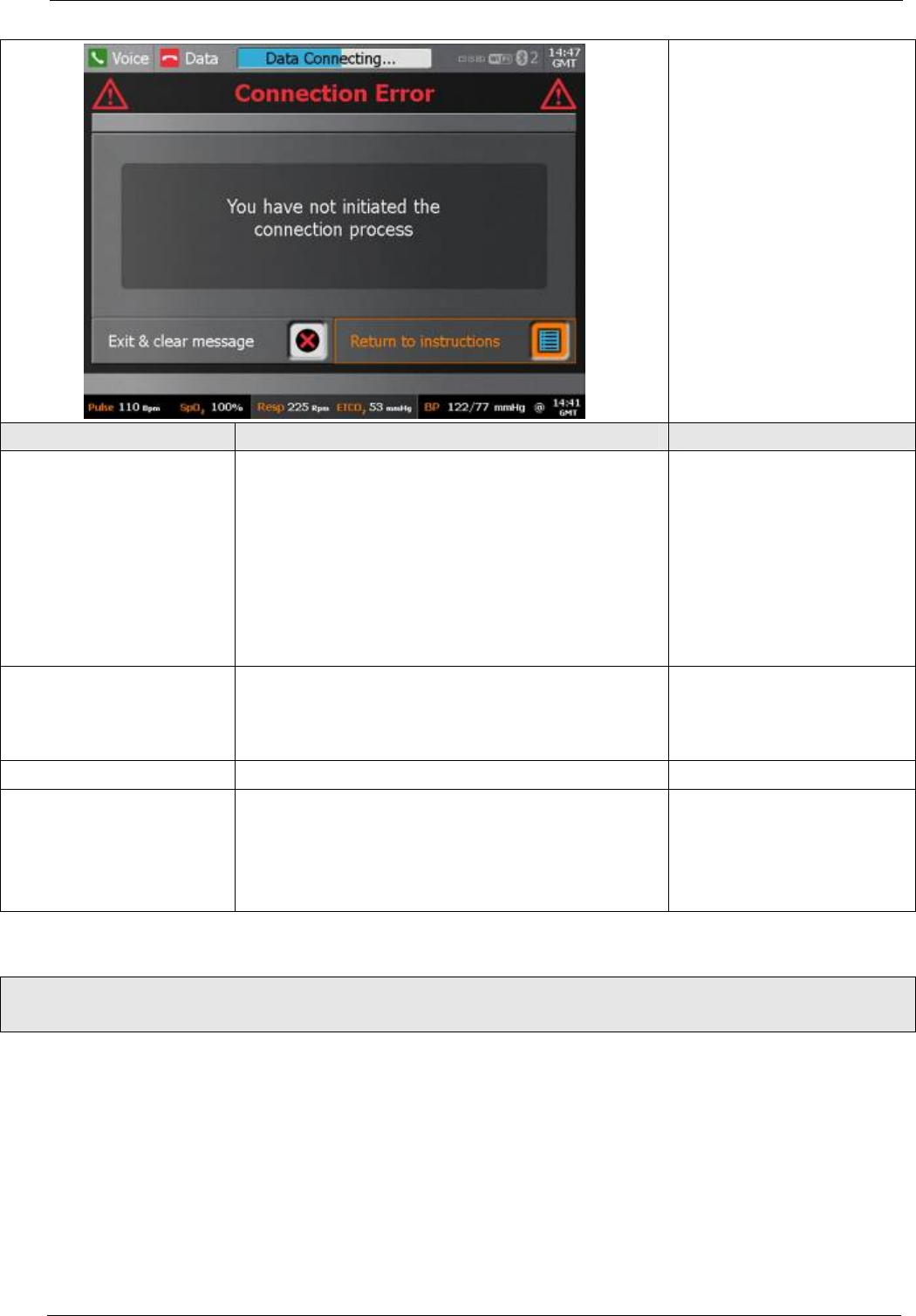
Tempus IC User/Operator Manual
Connetcion Error Dialog
shown.
Title Text Button(s)
Connection Error You have not initiated the connection process Left button: Exit & clear this
message allows user to exit
the connection process; and
go to the state requested by
the key that was pressed.
Right button (default): Return
to Instructions – returns to
connection process exactly
where it was before the key
press that triggered the error.
Voice Connection Error You have not initiated the voice connection process Left button: Exit & clear this
message (see above)
Right button (default): Return
to Instructions (see above)
- - - (not used)
ECG Lead-off ECG not plugged in or lead is not in good skin
contact
Left button: Exit & clear this
message
Right button: Return to ECG
instructions
10.5.8 Error Dialog - Type 3a
Error Dialog - Type 3a
(shutdown and wireless communication warnings)
Page 85 41-1001-00B
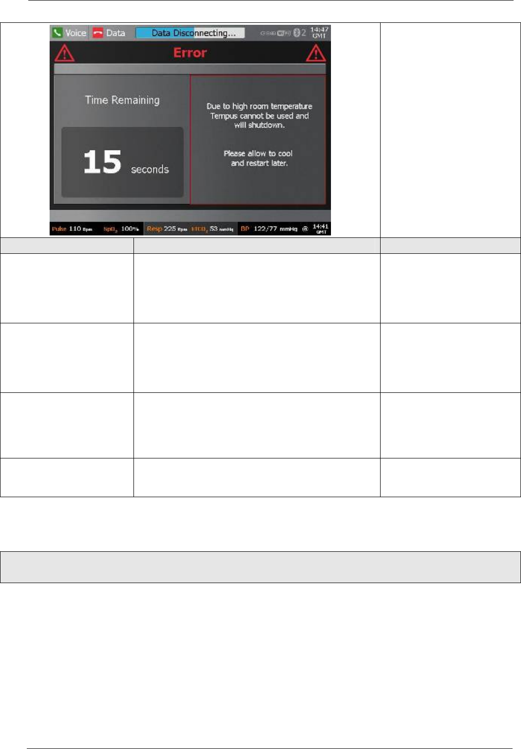
Tempus IC User/Operator Manual
Connetcion Error Dialog
shown.
Title Text Button(s)
Error A fault has occurred
To clear the problem Tempus will switch off
Please switch back on once the shut-down is
complete.
If the problem persists please contact your supplier
None
Error Due to low room temperature
Tempus cannot be used and
will shutdown.
Please allow to warm
and restart later.
None
Error Due to high room temperature
Tempus cannot be used and
will shutdown.
Please allow to cool
and restart later.
None
Battery Empty The battery is empty.
Tempus will perform a managed switch-off.
The battery should be changed.
None
10.5.9 Error Dialog - Type 3b
Error Dialog - Type 3b
(shutdown and wireless communication warnings)
Page 86 41-1001-00B
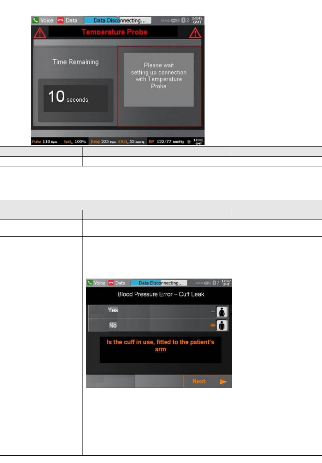
Tempus IC User/Operator Manual
Connection Error Dialog
shown.
Title Text Button(s)
Headset Please wait setting up connection to Headset None
10.5.10 Error Processes (Graphical Errors)
Error Process
Title Process Notes (for XML configuration) Button(s)
Pulse Ox Unplugged Process to plug sensor back in (never needs to be
unplugged)
Pulse Ox Finger Title: Pulse oximeter Error
Text: Is the pulse oximeter in use?: Yes / No
If user selects No then the
error is cleared.
If user selects Yes then help
to put sensor correctly on
finger.
Blood Pressure Error
Step 1: highlight in process
ribbon
Yes icon for cuff in use
No icon not in use (default
button is the not in use)
If “No” is selected when Next
is pressed the error is
cleared: no further steps.
If “yes” is selected when Next
is pressed proceed through
other steps.
Steps 2 to 5 help user to
check the cuff.
Final step button: “Restart
Readings”, this button starts
BP.
Blood Pressure Error BP timeout/ artefact
As above with different title.
Page 87 41-1001-00B

Tempus IC User/Operator Manual
Page 88 41-1001-00B
Blood Pressure Error BP weak signal/tube blocked
As above with different title.
Blood Pressure Error BP Over-pressure
As above with different title.
ECG lead-off
All leads
Process to step user through checking ECG harness.
Button: RESTART ECG at
end of process.
Keypad keys (eg HOME) to
cancel this error and goto the
process associated with the
button.
ECG lead-off LA Process to step user through checking ECG harness.
Button: RESTART ECG at
end of process.
Keypad keys (eg HOME) to
cancel this error and goto the
process associated with the
button.
ECG lead-off
V1, V2
Process to step user through checking ECG harness.
Button: RESTART ECG at
end of process.
Keypad keys (eg HOME) to
cancel this error and goto the
process associated with the
button.
ECG lead-off
V3, V4, V5, V6
Process to step user through checking ECG harness.
Button: RESTART ECG at
end of process.
Keypad keys (eg HOME) to
cancel this error and goto the
process associated with the
button.
10.5.11 Mode Specific Error Processes
The error processes below are mode specific, the XML configuration files will be stored on the disk in mode specific
directories so that the GUI uses steps appropriate to the mode in use. The principle for each error is the same,
there are steps to correct the fault.
At the end of the error process in some cases the function required is different. For example on data errors the
process may end with the user clearing the error without a re-try; in other modes the process may end with a re-
try/re-dial of the connection. The configuration file will need to handle these different final step unctions.
Title Process Notes (for XML configuration) Button(s)
Datalink Error These processes may have 2, 3, 4, 5, or 6 steps
defined in the XML configuration file.
The final screen in the process will have a default
key. This key may have 1 of 3 functions:
• Dial data
• Clear this message
• Backup mode
Variations depend on the mode, examples are:
• Landline datalink error 4 steps
As standard help process
with PREVIOUS, NEXT and
Final key defined in XML
files.
The XML file needs to allow
for 2 different keys at the end
of this process. In some
cases we tell the user to Dial
Data and in some cases
want to just clear the screen.

Tempus IC User/Operator Manual
Page 89 41-1001-00B
Dual POTS datalink error 10 steps
Datalink Error These processes may have 2, 3, 4, 5, or 6 steps
defined in the XML configuration file.
The final screen in the process will have a default
key. This key may have 1 of 3 functions:
• Dial data
• Clear this message
• Backup mode
Variations depend on the mode, examples are:
• Landline datalink error 4 steps
Dual POTS datalink error 10 steps
As standard help process
with PREVIOUS, NEXT and
Final key defined in XML
files.
The XML file needs to allow
for 2 different keys at the end
of this process. In some
cases we tell the user to Dial
Data and in some cases
want to just clear the screen.
Voicelink Error These processes may have 2, 3, 4, 5, or 6 steps
defined in the XML configuration file.
The last screen in the process will have a default key.
This key may have 1 of 2 functions:
• Dial voice
• Clear this message
As standard help process
with PREVIOUS, NEXT and
Final key defined in XML
files.
The XML file needs to allow
for 2 different keys at the end
of this process. In some
cases we tell the user to Dial
Voice and in some cases
want to just clear the screen.
Datalink Error
or
Data-cable Error
Or
IFE Seatbox Error
These processes may have 2, 3, 4, 5, or 6 steps
defined in the XML configuration file.
The last screen in the process will have a default key.
This key will always be to:
• Dial data
As standard help process
with PREVIOUS, NEXT.
Voicelink Error
Or
Voice-cable Error
Or
IFE Seatbox Error
These processes may have 2, 3, 4, 5, or 6 steps
defined in the XML configuration file.
The last screen in the process will have a default key.
This key will always be to:
• Dial voice
As standard help process
with PREVIOUS, NEXT
Cellphone Error • GSM Datalink Error 3 steps
Last step in process will be
button:
Dial Data
Wifi Error • Wifi datalink error eg 4 steps
Last step in process will be a
button for either attempting a
new connection or switching
mode.
Dial Data
Backup mode
Satellite Terminal Error Satellite terminal error eg 4 steps Last step in process will be
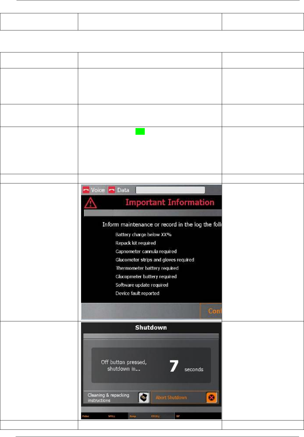
Tempus IC User/Operator Manual
button:
Dial Data
10.5.12 Shutdown Error Processes
State Description
Comments / Related
Variables
Headset Replaced Check headset is docked onto the charger before
powering down. Triggers single Headset Not
Replaced error.
User can acknowledge error
and leave the headset if they
need to shutdown anyway so
the error must not be
repeated.
Important Information
Screen Displays list of important reminders for the user
relating typically to logging for repack/replenishment
etc.
Button for user to confirm
they have read the items on
the list.
Shutdown (countdown) Countdown starts at 10s, counts down in seconds
Powers off when countdown reaches 0s.
If user requests Clearning and Repacking
Instructions the power-down is cancelled and help
screen for cleaning and repacking displayed.
Headset not replaced: standard error dialog. Button: Clear this message.
Button: confirmed
Buttons:
Cleaning & repacking:
cancels the shut down
and returns to repacking
menu.
Abort shutdown: cancels
the shutdown.
Page 90 41-1001-00B

Tempus IC User/Operator Manual
Page 91 41-1001-00B
11 Spares List
11.1 Spares List of the Tempus IC
The following user-replaceable accessories and consumables are available from the RDT.
01-1001 Battery Pack
01-1002 Blood Pressure Cuff – Adult
01-1003 Blood Pressure Cuff – Large Adult
01-1004 Blood Pressure Cuff – Child
01-1005 Lo-Flo® Capnometer
01-1006 Blood Pressure Hose
01-1007 Capnometer Cannula - Adult Nasal
01-1008 Pulse Oximeter Sensor
01-1009 Extension Reel
01-1010 12 Lead ECG Harness
01-1011 BluetoothTM Thermometer
01-1012 Battery Charger
01-1013 BluetoothTM Glucometer
01-1014 Dual Modem Cable
01-1015 Mains Cable Pack
01-1016 Bag (empty)
01-1017 Mains Power Supply
01-1018 BluetoothTM Headset
01-1019 Wired Headset
01-1020 Consumables Replenishment Kit
01-1021 Ethernet Cable
01-1022 USB - Serial Cable
01-1023 Ethernet Cable to Modem Adaptor
01-1024 Glucometer Replenishment Kit
01-1025 ECG wrist straps
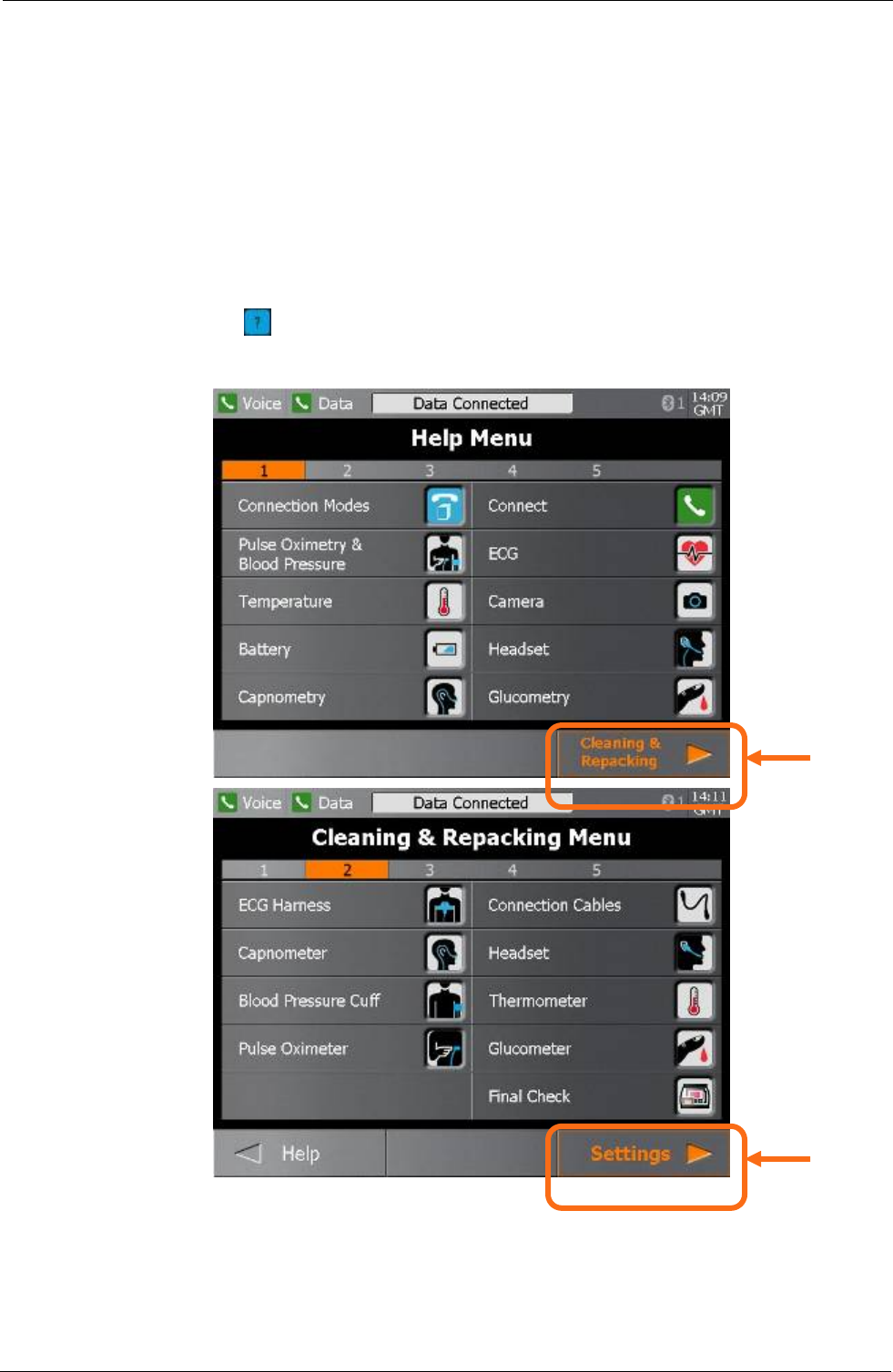
Tempus IC User/Operator Manual
12 Thermometer Units, Screen Brightness & Audible
Alerts Configurations
NOTE: The iAssist help processes on your Tempus IC may differ from this example iAssist help
process in the following sections. However the process always follows the same key
elements.
NOTE: Always ensure that you read the complete iAssist help process in order and do exactly what it
requires.
A number of the parameters used by Tempus IC are configurable to suit certain requirements,
i.e. Thermometer Units, Screen Brightness & Audible Alerts.
First, press the button to bring up the Help Menu. Then to access the Settings menu press
Cleaning and Repacking touchscreen button followed by pressing the Settings touchscreen
button.
Press the Settings button in the Cleaning & Repacking Menu on the touchscreen to bring up
the Settings Menu.
Press the
touchscreen
here
Press the
touchscreen
here
Page 92 41-1001-00B
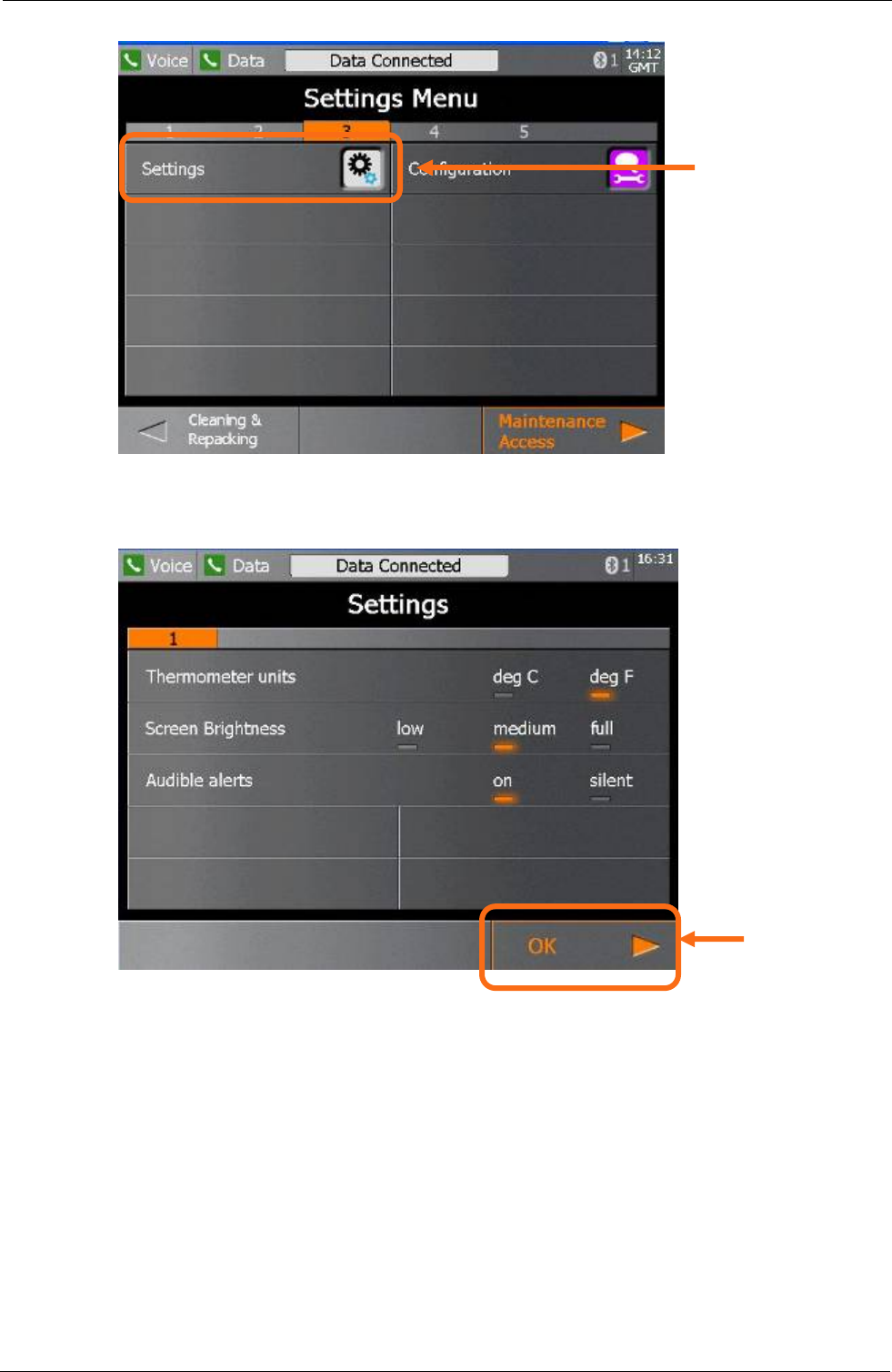
Tempus IC User/Operator Manual
Press the Settings button in the Settings Menu on the touchscreen to bring up the
configurable options.
Press the touchscreen to select the configurable parameters and press OK touchscreen button
to confirm the changes you have made.
Press the
touchscreen
here
Press the
touchscreen
here
Page 93 41-1001-00B

Tempus IC User/Operator Manual
Page 94 41-1001-00B
13 Specifications and Standards
13.1 Specifications
Note that all figures quoted are based on room temperature, pressure and humidity unless otherwise stated.
13.1.1 Non-invasive Blood Pressure
13.1.1.1 Adult cuff and Large Adult cuff ratings
Systolic 60 - 250 mmHg
Diastolic 40 - 220 mmHg
Range 0 - 330 mmHg
Accuracy ± 3mmHg or ± 2% (whichever is greater)
Resolution 1 mmHg
Maximum inflation 330mmHg
13.1.1.2 Child cuff ratings
Systolic 60 - 250 mmHg
Diastolic 40 - 220 mmHg
Range 0 - 330 mmHg
Accuracy ± 3mmHg or ± 2% (whichever is greater)
Resolution 1 mmHg
Maximum inflation 330mmHg
13.1.2 ECG Recorder
ECG Specifications
Gain/Sensitivity 5, 10, 20 mm/mV
Input Range ±6mV
Acquisition sample rate 1000 samples per second (compressed to
500Hz with peak picking and averaging
algorithm)
Frequency response 0.05 to 175Hz ±3dB
Defibrillator protection Patient leads are isolated from system and
operator, with 4kV protection
Common Mode Rejection -60dB (minimum)
Safety Standards Complies with AAMI EC11, EN60601-1,
EN601-1-2, and EN601-2-25
Leads Off Indicators Connection status for each lead is shown on
Acquisition screen
Permanent Filters High Pass: 0.05Hz 1st order
Low Pass: 170Hz 1st order
Baseline Wander: Baseline reset by adaptive
zeroing algorithm
Notch filter (Mains Noise Rejection) 50Hz 4th order Butterworth,
49.1Hz - 50.9Hz,
60Hz 4th order Butterworth,
59.1Hz - 60.9Hz
Low pass (Muscle Artifact Filter) 35Hz 4th order

Tempus IC User/Operator Manual
Page 95 41-1001-00B
13.1.3 ETC02 Sensor
Unless otherwise stated, all CO2 measurements are made following an airway adapter zero,
with 5% CO2 gas, balance N2 at 25 degrees C, and Pb = 760 mmHg with 2 liters per minute
flow. The stabilization time for full specification testing of the LoFlo Module over the entire
temperature range is 20 minutes.
Range 0-100 BPM
Accuracy ± 2 BPM
Range 0-10% CO2 displayed value
Accuracy ± 4%
Rise time <2 seconds
Delay time 5 seconds
Operating altitude range 0-15000 feet
LoFlo sidestream Capnometer - SPECIFICATIONS
Carbon Dioxide Monitoring:
Mode of Sampling
Sidestream
Principle of Operation
Non-dispersive infrared (NDIR) single beam optics, dual
wavelength, no moving parts.
Initialization Time Capnogram displayed in less than 20 seconds, At an ambient
temperature of 25° C, full specifications within 2 minutes.
CO2 Measurement Range 0 to 150 mmHg 0 to 19.7% 0 to 20 kPa (Barometric Pressure
supplied by RDT Ltd)
CO2 Calculation Method BTPS (Body Temperature Pressure Saturated)
CO2 Response Time <3 seconds - includes transport time and rise time
CO2 Resolution 0.1 mmHg 0 to 69 mmHg 0.25 mmHg 70 to 150 mmHg
CO2 Accuracy * 0 - 40 mmHg ± 2 mmHg
41 - 70 mmHg ± 5% of reading
71 - 100 mmHg ± 8% of reading
101 - 150 mmHg ± 10% of reading
Above 80 breath per minute ± 12% of reading
* NOTE: Gas temperature at 25° C.
CO2 Stability Short Term Drift: Drift over four hours shall not exceed 0.8
mmHg maximum. Long Term Drift: Accuracy specification will
be maintained over a 120 hour period.
CO2 Noise RMS noise of the sensor shall be less than or equal to 0.25
mmHg at 5% CO2
Sampling Rate 100 Hz
Respiration Rate Range 2 to 150 breaths per minute (BPM)

Tempus IC User/Operator Manual
Page 96 41-1001-00B
LoFlo sidestream Capnometer - SPECIFICATIONS
Carbon Dioxide Monitoring:
Respiration Rate
Accuracy
± 1 breath
Calibration No routine user calibration required.
Safety lock-outs:
• System does not allow sample cell zero for 20 seconds after
the last breath is detected.
• System does not allow sample cell zero if temperature is not
stable.
• An adapter zero cannot be performed if a sample cell is not
connected to the module
ETCO2 Calculation Method: Peak of the expired CO2 waveform
Selections: 1 breath, 10 second, 20 second
Inspired CO2
Measurement
Range: 3 to 50 mmHg
Method: lowest reading of the CO2 waveform in the previous
20 seconds
Selection: 20 seconds (not user-selectable)
Compensations (RDT Ltd
Controlled)
Compensations for: Expired O2, Balance gas (N2, N2O, He)
and Anesthetic AgentsB
Uses gas compensation information and barometric pressure
to correct the raw carbon dioxide value
O2 Compensation Range: 0 to 100%
Resolution: 1%
Default: 16%
N2O Compensation Range: 0 (off) or 1 (on)
Default: Off
Note: If ON, the monitor assumes the balance of the mixture is
O2
He Compensation Range: 0 (off) or 1 (on) Default: Off
Note: If ON, the monitor assumes the balance of the mixture is
O2
Airway Pressure Range:
+ 120 cmH2O (88.27 mmhg)
- 45 cmH2O (33.1 mmHg).

Tempus IC User/Operator Manual
Page 97 41-1001-00B
LoFlo sidestream Capnometer - SPECIFICATIONS
Carbon Dioxide Monitoring:
Anesthetic Agent SensitivityA
(uncompensated)
Accuracy specification will be
maintained for halogenated
anesthetic agents present at
accepted MAC (Minimum
Alveolar Concentration)
clinical levels.
Anesthetic Agent Effects
(MAC levels)
Anesthetic Agent Sensitivity
(compensated)
Testing at Agent levels
defined by accepted
regulatory standards (i.e. ISO
21647, ASTM F1456,
IEC/CDV 60601-2-55)
currently in process.
Cross-sensitivity
Compensation Error*
0-40 mmHg: ± 1 mmHg additional error
41-70 mmHg: ± 2.5% additional error
71-100 mmHg: ± 4% additional error
101-150 mmHg: ± 5% additional error
* Additional worst case error when compensation for Pb, O2,
N2O, anesthetic agents, or helium is correctly selected for the
actual fractional gas constituents present.
Gas or Vapor Halothane Enflurane Isoflurane Desflurane
MAC Level %
(v/v)
0.74 1.68 2.00 6.30
(From Olivier C. Wenker: Review of Currently Used Inhalation Anesthetics: Part I. The Internet
Journal of Anesthesiology, 1999, Volume 3 Number.)
Gas or Vapor Gas Level Quantitative Effects
Nitrous oxide 60% No Additional Effect
Halothane 4% No Additional Effect
Enflurane 5% No Additional Effect
Isoflurane 5% No Additional Effect
Sevoflurane 5% No Additional Effect
Xenon 80% Negatively bias Carbon
Dioxide values by up to an
additional 5 mmHg at 38
mmHg
Helium 50% No Additional Effect
Metered dose inhaler
propellants
Unspecified Unspecified

Tempus IC User/Operator Manual
Page 98 41-1001-00B
Desflurane 15%
Concentrations greater than
5% will positively bias
Carbon Dioxide values by up
to an additional 3 mmHg at
38 mmHg.
Ethanol 0. 1% No Additional
Effect
Isopropanol 0.1% No Additional
Effect
Acetone 0.1% No Additional
Effect
Methane 1% No Additional
Effect
(From ISO 21647, Medical electrical equipment – Particular requirements for the basic safety
and essential performance of respiratory gas monitors, Table 105.)
LoFlo sidestream Capnometer - SPECIFICATIONS
Physical Characteristics and Host Interface:
Physical characteristics Module weight is less than 9.6 oz (272.16 g)
Module Size: < 2.6" wide x 1.5" high x 3.5" deep [< 66.0 x 38.1
x 88.9 mm]
Cable length – 22 inches (55.88 cm)
LoFlo Sidestream Capnometer - SPECIFICATIONS
Environmental:
Temperature and
Humidity Operating
0 to 40°C, 10 to 90% RH, non-condensing
Storage -40 to 70°C, 10 to 90% RH, non-condensing
Atmospheric Pressure
Storage
400-800 mmHg
Water Resistance IPX4 - Splash-proof - Module only (When Sample Cell is
inserted into Sample Cell Receptacle)
Shock Impact IEC TR 60721-4-7 Class 7M3 (designed to withstand
environments subject to significant vibrations or high shock
levels)
EN60068-2-27 Shock
EN60068-2-64 Random Vibration
Mechanical:
Mechanical strength Cable Strain Relief, resistance to pull-out: Cable strain (bend)
relief system for the sensor enclosure shall withstand a pull of
30 pounds without failure to either the cable or the enclosure.
Cable Strain Relief, flexibility: The connector strain relief
system shallwithstand 10,000 bend cycles.

Tempus IC User/Operator Manual
Page 99 41-1001-00B
LoFlo Sidestream Capnometer - SPECIFICATIONS
Connector Retention Force: The average retention force of the
standardconnector when pulling on the cable shall be 90
Newtons (20 pounds).
13.1.4 Sp02 Sensor
Range 30-240 bpm
Graphic display range 50-200 bpm
Accuracy ± 3bpm or ±2% whichever is greater
Resolution 1%
Range 50% to 100%
Graphic display range 50-100%
Accuracy ±2% at 70%-100%, ±3% at 50%-69%
Type Functional saturation (test methods available upon
request)
Wavelength range Red 660nm, infra-red 905nm
13.1.4.1 SpO2
Monitor
%SpO2 Range: 0 – 100% with Extended Micro Power Mode
0 – 100% with Digital Micro Power Mode
Resolution 1%
Accuracy: Adult: ±2 @ 70-100% less than 70% is undefined
Neonate: ±3 @ 70-100% SpO2 less than 70% is
undefined Arms = 1
Averaging: 2 (Sleep mode), 4, 8, or 16 pulses (default = 8)
The lower the number the more responsive the display.
Pulse Rate Range: 30 - 254 BPM with Extended Micro Power Mode
25 - 300 BPM with Digital Micro Power Mode
Resolution 1 BPM
Accuracy: greater of ±2 BPM or ±2%
Arms = 1
Averaging: 8 seconds
13.1.5 Environmental Specifications
Altitude 0-4500m (0-15000ft)
(can be used at higher physical altitudes provided the
local atmosphere is no higher than 4500m, e.g. in a
pressurised aircraft cabin)
Relative humidity 15%-95% (non-condensing)
Operating temperature range 0ºC to 40ºC
Storage temperature range -20ºC to +60ºC
Environmental protection IPX5), 20G shock
NOTE: Note that the IP sealing has a warranty of 1 year.
NOTE: IP66 and MIL810F tests are lab tests and not normal condition. Unit remains intact
and functional after tests but rough handling may degrade performance specification
i.e. if you hit it with steel ball then IP sealing around the case may degrade, if you
drop it from 1.2m then IP sealing may degrade and a drop tests may damage

Tempus IC User/Operator Manual
Page 100 41-1001-00B
peripherals. Drop test performance specifications relate to a standalone device with
no cables connected.
13.1.6 Miscellaneous Features and Specifications
Dimensions H 256mm, W 294mm, D 273mm
13.1.6.1 Mass 7.2kg (without batteries)Rechargeable battery
Battery life At least 6 hours running in normal use.
Nominal voltage 7.4V
Charging voltage 8.4V ±1%
Nominal capacity 7.8Ah
Weight 0.25kg
Shelf life Approximately 70% remaining after 1 year (before the
charge indicator light turns to Amber)
Battery shelf life and run times are based on a new, fully charged battery stored in normal room ambient conditions. Run time is based
on RDT’s model of typical device usage in an incident.
13.1.6.2 Battery Charger
Mains input voltage 100-240V
Frequency 50-60Hz
Input current 0.9A
Output voltage 8.4V dc
Output current <2.7A3A
Charge time (from empty) 6 hours
NOTE: Only the RDT Battery Charger pn 01-1012 can be used with the Tempus IC.
13.1.6.3 Mains Power Supply
Mains input voltage 100-240V
Frequency 50-60Hz
Input current 0.55A
Output voltage 12V dc
Output current 5A
NOTE: Only the Cincon Electronics TR60M12 as supplied by RDT can be used with the
Tempus IC.
13.1.7 Communications
13.1.7.1 Transmission rates
ECG data and video images take an appreciable amount of time to send to the Response
Centre, approximate times are as follows:
• 12 lead ECG – 2-3 minutes
• Low resolution video image - about half a minute
• High resolution video images – 2-3 minutes.
These times are for guidance only and are based on the worst case communications system
(off-aircraft satellite link running at 2.4Kbaud V22BIS) and may vary depending on the quality of
the connection.

Tempus IC User/Operator Manual
Page 101 41-1001-00B
13.1.7.2 WiFi Specification
The WiFi technology used by the Tempus operates using IEEE 802.11b and 802.11g standard.
It operates in the Industrial, Scientific and Medical (ISM) band between 2.412GHz and
2.484Hz.
The WiFi technology has the following features:
WiFi Specification
SKU #
North America WL6221-668
International WL6227-674
Transmit Power
CCK: 12 dBm typical
OFDM: 9 dBm typical
63mW emission designation 11M5F9W to spec RSS210
Indoor Range ~ 300 feet (typical office environment)
Standards
Conformance Wi-Fi Certified
Meets 802.1x requirements
WPA2-Enterprise
IEEE 802.11b and 802.11g
Certification/
Compliance
FCC: Part 15, Class C FCC ID LUBP300SD-1
Industry Canada license 2529A-WLANSDIO
Data Rate:
802.11g: Data rate dynamically shifts between 54, 48, 36, 24, 18, 12, 9
and 6 Mbps based on signal strength, for maximum availability and
reliability of connection. OFDM with BPSK, QPSK, 16-QAM and 54-QAM
(at 6/9, 12/18, 24/36, and 48/54 Mbps, respectively)
802.11b: Data rate dynamically shifts between 11, 5, 5M, 2M, and 1
Mbps based on signal strength, for maximum availability and reliability of
connection. (802.11g: DSSS with BPSK, QPSK, and CCK (at 1,2, and
5.5/11 Mbps, respectively)
Frequency Range: North America: 2.412-2.462 GHz, channels 1-11
Europe ETSI: 2.412-2.472 GHz, channels 1-13
Japan: 2.412-2.484 GHz, channels 1-14
Security
Encryption/Authe
ntication
Hardware
Support:
WEP: Open and Shared
WP
A
-PSK, WPA2-PSK (Personal): TKIP and AES-CCMP encryption
WP
A
-E, WPA2-E (Enterprise): TKIP, AES-CCMP, and all EAP
authentication processes including LEAP, EAP-TLS, EAP-FAST, PEAP
0 (PEAPMSCHAP), PEAP 1 (PEAP-GTC) and EAP-TTLS
− Wi-Fi Multimedia (WMM), a standard for Quality of Service (QoS)
13.1.7.3 Bluetooth Specification
Bluetooth Specification
Description Specification Note
Operating
frequency range
(2400 ... 2483,5) MHz
ISM Band
Range Class 1, range up to 300 meters

Tempus IC User/Operator Manual
Page 102 41-1001-00B
Lower guard band 2 MHz
Upper guard band 3,5 MHz
Carrier frequency 2402 MHz ... 2480 MHz f = 2402 + k,
k = 0...78
Modulation method GFSK (1 Mbps)
P/4 DQPSK (2Mbps)
Hopping 1600 hops/s, 1 MHz channel space
GFSK: Asynchronous, 723.2 kbps / 57.6 kbps
Synchronous: 433.9 kbps / 433.9 kbps
P/4
DQPSK:
Asynchronous, 1448.5 kbps / 115.2 kbps
Synchronous: 869.7 kbps / 869.7 kbps
Maximum data rate
8DQPSK: Asynchronous, 2178.1 kbps / 177.2 kbps
Synchronous: 1306.9 kbps / 1306.9 kbps
Receiving signal
range
-82 to -20 dBm
Typical
condition
Receiver IF
frequency 1.5 MHz Center
requency
Min -11 ... -9 dBm
Max +14 ... +18 dBm
Transmission
power
RSS210 22mW emission designation 1M21G2D
RF input
impedance 50Ω
Compliance Bluetooth specification, version 2.0 + EDR
Certification/
Compliance
FCC: Part 15, FCC ID QOQWT11
Industry Canada license 5123A-BGTWT11E
13.1.7.4 Bluetooth Headset Specification
The TempusIC uses the Bluetrek G3 wireless headset. This is unmodified by RDT and is
provided under FCC ID QITBTG3 under FCC part 15C and under AusCom approval N1342
It operates in the frequency bands 2402MHz – 2480MHz and has a maximum power of
0.00297W.
Wireless Performance Specifications
Description Transmitter Receiver
Operating frequency range 2402 - 2480 MHz 2402 - 2480 MHz
Type of modulation
FHSS modulation FHSS modulation
Number of channels 79 79
Channel separation 1MHz 1MHz
Type of antenna Ceramic type
Antenna gain (dBi) 0
Power level Fixed

Tempus IC User/Operator Manual
Page 103 41-1001-00B
Description General Specifications
Bluetooth type V1.2 class 2
Range 10m max (open field)
Weight 12g
Size 67.5mm x 19.5mm
Talk time Up to 13 hours*
Stand by time Up to 400 hours*
*Based on the manufacturer’s specification – can be 12.5 hours in HV3, 10 hours in HV2 and
5.3 hours in HV1 modes (HV level set by host device).
13.1.7.5 FCC & Industry Canada Notes on Wireless Communications
FCC ID: ROSTEMPUSIC
CAUTION: Do not disassemble the device. There are no user-serviceable parts inside.
Refer servicing to the manufacturer. Changes or modifications not
expressly approved by RDT could void the user’s authority to operate the
equipment.
This equipment has been tested and found to comply with the limits for a Class B digital
device, pursuant to part 15 of the FCC rules and Industry Canada Radio Standard RSS 210.
These limits are designed to provide reasonable protection against harmful interference in a
residential installation.
This equipment generates, uses and can radiate radio frequency energy and, if not installed
and used in accordance with the instructions, may cause harmful interference to radio
communications. However, there is no guarantee that interference will not occur in a
particular installation.
If this equipment does cause harmful interference to radio or television reception, which can
be determined by turning the equipment off and on, the user is encouraged to try to correct
the interference by one or more of the following measures:
• Reorient or relocate the receiving antenna.
• Increase the separation between the equipment and receiver.
• Connect the equipment into an outlet on a circuit different from that to which the
receiver is connected.
• Consult the dealer or an experienced radio/TV technician for help.
Operation is subject to the following two conditions:
• This device may not cause interference and
• This device must accept any interference, including interference that may cause
undesired operation of the device.
This equipment is also ETS 300 328, ETS 300 826, ETS 300 328-2, ETS EN301 489-1 and
ETS EN301 489-17 compliant. These limits are designed to provide reasonable protection
against harmful interference when the equipment is operated in a commercial environment.
The user may find the following booklet helpful: How to Identify and Resolve Radio-TV
Interference Problems. This booklet is available from U.S. Government Printing Office,
Washington, D.C. 20402.
Radio Frequency Interference Requirements – Canada
This Class B digital apparatus meets the requirements of the Canadian Interference-Causing
Equipment Regulations.
13.1.7.6 Ethernet Specification
The Ethernet connection has the following specifications:
• IEEE 802.3 compliant

Tempus IC User/Operator Manual
Page 104 41-1001-00B
• RJ-45 connection
• DHCP or fixed IP, Mask, Gateway and DNS
• Optional Type of Service setting
• Protocol: TCP Port 2167
• Network diameter: at least 100m
13.1.8 Classification
The system is classified according to the requirements of EN60601-1:1990 inc. A13:1996, the
standard for Medical Electrical Equipment, Part 1, General Requirements for Safety, Clause 5
as:
5.1 The Tempus IC is Internally (battery) powered – when powered by an external power
supply it is class II as defined by the classification labelled on the power supply
specified and supplied by RDT.
5.2 Applied parts type CF defibrillator proof (ECG electrodes), type BF defibrillator proof
(capnometer cannula, pulse oximeter probe, non-invasive blood pressure cuff) and
type BF (thermometer).
5.3 IPX5, protected against rainfall according to IEC529 (with the display closed)
5.4 No parts supplied sterile or suitable for/requiring sterilising
5.5 Equipment not suitable for use in the presence of a flammable anaesthetic mixture
with air or with oxygen or nitrous oxide
5.6 Suitable for continuous use (8 hours maximum before the battery will require
replacement).
13.1.9 Standards Compliance
The Tempus IC complies with the applicable parts of the following standards:
• IEC/EN60601-1:1990 inc. amendment A2:1995 and A13:1996, general requirements for
the safety of electrical medical products
• IEC/EN60601-1-2:2001, collateral requirements for electromagnetic compatibility,
requirements and tests
• IEC 60601-1-4, First edition, 1996 Collateral standard: programmable electrical medical
systems (software)
• IEC 60601-2-27, First edition, 1994 Particular requirements for electrocardiographic
monitoring equipment
• IEC 60601-2-30, First edition, 1995 Particular requirements for automatic cycling indirect
blood pressure monitoring equipment
• ISO 9918, First edition, 1993 Particular requirements for capnometers for use with humans
• ISO 9919, First edition, 1992 Particular requirements for pulse oximeters for medical use
• RTCA/DO-160D/E Environmental conditions and test procedures for airborne equipment
• EN60529:1992 Degrees of protection provided by enclosures (approved to IPX1)
• BS2G 239:1992 Specification for Primary active lithium batteries for use in aircraft
• 3GPP TS 51.010-1 Digital cellular telecommunications system (Phase 2+); Mobile Station
(MS) conformance specification; Part 1: Conformance specification
• ETSI EN 301 489-1 V1.4.1 (2002-08) Electromagnetic compatibility and Radio Spectrum
Matters (ERM); Electromagnetic Compatibility (EMC) standard for radio equipment and
services; Part 1: Common technical requirements.
• ETSI EN 301 489-7 V1.2.1 (2002-08) Electromagnetic compatibility and Radio spectrum
Matters (ERM); ElectroMagnetic Compatibility (EMC) standard for radio equipment and
services; Part 7: Specific conditions for mobile and portable radio and ancillary equipment
of digital cellular radio telecommunications systems (GSM and DCS).
• ANSI C63.4:2001 Methods of Measurement of Radio-Noise Emissions from Low-Voltage
Electrical and Electronic Equipment in the Range of 9 kHz to 40 GHz - as required by the
US CFR 47 Part 15 B & C (FCC requirements for intentional transmitters).

Tempus IC User/Operator Manual
Page 105 41-1001-00B
• ETSI EN 300 328 V1.4.1 (2003-04) Electromagnetic compatibility and Radio spectrum
Matters (ERM); Wideband transmission systems; Data transmission equipment operating in
the 2,4 GHz ISM band and using wide band modulation techniques; Harmonized EN
covering essential requirements under article 3.2 of the R&TTE Directive
• ETSI EN 301 489-17 V1.2.1 (2002-08) Electromagnetic compatibility and Radio spectrum
Matters (ERM); ElectroMagnetic Compatibility (EMC) standard for radio equipment and
services; Part 17: Specific conditions for 2,4 GHz wideband transmission systems and 5
GHz high performance RLAN equipment
• ETSI EN 301 511 V7.0.1 (2000-12) Global System for Mobile communications (GSM);
Harmonized standard for mobile stations in the GSM 900 and DCS 1800 bands covering
essential requirements under article 3.2 of the R&TTE directive (1999/5/EC)
• ETSI EN 300 328 V1.6.1 – Electromagnetic compatibility and Radio spectrum Matters
(ERM); Wideband transmission systems; Data transmission equipment operating in the 2.4
GHz ISM band and using wide band modulation techniques; Harmonized EN covering
essential requirements under article 3.2 of the R&TTE Directive.
• ETSI EN 301 489-17 V 1.5.1 (2004-11) – Electromagnetic Compatibility (EMC) standard for
radio equipment and services; Part 17: Specific Conditions for 2.4 GHz wideband
transmission systems and 5 GHz high performance RLAN equipment.
• EN 301 489-17 v1.11 (2000-09) Specified Conditions for Wideband Data and HIPERLAN
Equipment
• EN61000-4-2 – Electromagnetic Compatibility for Industrial Process Measurement and
Control Equipment, Part 2: Electrostatic Discharge Requirements.
• EN61000-4-3 – Electromagnetic Compatibility for Industrial Process Measurement and
Control Equipment, Part 3: Radiated Electromagnetic Field Requirements.
• ANSI C95.1 Safety Levels with Respect to Human Exposure to RF Electromagnetic Fields
300 KHz to 300 GHz
• EN 55022:1998+A Information technology equipment. Radio disturbance characteristics.
Limits and methods of measurement
• EN 55022:2000+A3 Information technology equipment - Radio disturbance characteristics -
Limits and methods of measurement
• EN 55022:2003 Class B Limits and Methods of Measurement of Radio Interference
Characteristics Information Technology Equipment.
• EN 61000-3-2:2001 Electromagnetic compatibility (EMC). Limits. Limits for harmonic
current emissions (equipment input current up to and including 16 A per phase)
• EN 61000-3-3:1995 A1:2001 Electromagnetic compatibility (EMC) - Part 3-2: Limits - Limits
for harmonic current emissions (equipment input current up to and including 16 A
• EN 61000-4-3:2002 Incorporating Amendments Nos. 1 and 2 - Electromagnetic
compatibility (EMC) -Part 4-3: Testing and measurement techniques - Radiated,
radio-frequency, electromagnetic field immunity test
• EN 61000-4-4:1995 A1:2000 Electromagnetic compatibility (EMC) - Part 4-4: Testing and
measurement techniques - Electrical Fast Transient/Burst Immunity Test
• EN 61000-4-5:1995 A1:2000 Electromagnetic compatibility (EMC) - Part 4-5: Testing and
measurement techniques - Surge immunity test
• EN 61000-4-6:1996 A1:2000 Immunity to Conducted Disturbances, Induced by Radio
Frequency Fields
• EN 61000-4-11:1994 A1:2000 Voltage Dips, Short Interruptions and Voltage Variations
Immunity Tests
13.1.10 Other Standards Being Used for Reference Purposes
The following standard is used for reference in the design of the Tempus IC:

Tempus IC User/Operator Manual
Page 106 41-1001-00B
• IEC/EN60945:1997 Maritime navigational equipment - General requirements - Method of
testing and required test results
13.1.11 Cable Length of the Sensors and the Accessories
RDT Part
Number
Cable
Length
(typ.)
Tested
Length
Ethernet cable 01-1021 2.1m 2.1m
SpO2 sensor 01-1008 1.5m 1.5m
ECG harness 01-1010 1.5m 1.5m
Capnometer 01-1005 0.5m 0.5m
Wired headset 01-1019 1.2m 1.2m
Mains Power supply 01-1017 0.45m 0.45m
Mains lead 01-10@@ 2m 2m
Warning! The use of longer cable lengths may cause an increased emission or a reduced
interference resistance. The use of other sensors or cables except the ones mentioned above
is not allowed.
13.1.12 Manufacturer's Declaration - Electromagnetic Emissions (Tab. 201
according to DIN EN 60601-1-2)
The Tempus IC is intended for use in an electromagnetic environment as described below. The
customer or user of the device should ensure that the device is used in such an environment.
Emission
Measurements Compliance Electromagnetic Environment
HF emissions acc. to
CISPR11
Group 2 The Tempus IC must emit RF energy in order
to perform its function. Nearby electronic
devices may be affected.
Note that the Tempus IC can be configured
for not to emit RF energy in which case it will
be group 1 and will not be likely to cause any
interference in nearby electronic equipment.
HF emissions acc. to
CISPR11
Class B The Tempus IC is intended for use in all
facilities including living quarters and such
ones which are connected directly to a public
power supply that supplies also buildings
used for living purposes.
Emission of overtones
acc. to IEC61000-3-2
Class A
Emission of voltage
fluctuation/flicker acc.
to IEC61000-3-3
Complies
13.1.13 Manufacturer's Declaration - Electromagnetic Emissions (Tab. 202
according to DIN EN 60601-1-2)
The Tempus IC is intended for use in an electromagnetic environment as described below. The
customer or user of the device should ensure that the device is used in such an environment.
Interference
Resistance Test IEC 60601 Test
Level Compliance Level Electromagnetic
Environment -

Tempus IC User/Operator Manual
Page 107 41-1001-00B
Guidelines
Electrostatic
discharge (ESD) acc.
to IEC 61000-4-2
± 6 kV contact
discharge
± 8 kV air discharge
± 6 kV contact
discharge
± 8 kV air discharge
Floors should be of
wood, concrete or
ceramic tiles. If the
floor is tiled with
synthetic material the
relative air humidity
must have 30 % at
least.
Fast transient electric
disturbances / bursts
acc. to IEC 61000-4-
4
± 2 kV for power
lines
± 1 kV for input and
output lines
± 1 kV for input and
output lines
The quality of the
supply voltage should
conform to a typical
business or clinic
environment.
Surge voltage
acc. to IEC 6100-4-5
± 1 kV normal mode
voltage
± 2 kV common
mode voltage
± 1 kV normal mode
voltage
± 2 kV common
mode voltage
Mains power should be
that of a typical
hospital or commercial
environment.
Voltage drops, short
interruptions and
variations in supply
voltage acc. to
IEC 61000-4-11
< 5 % UT (>95 %
break of UT for 0,5
period
40 % UT (60% break
of UT) for 5 periods
70 % UT (30% break
of UT) for 25 periods
< 5 % UT (>95 %
break of UT for 5
seconds
< 5 % UT (>95 %
break of UT for 0,5
period
40 % UT (60% break
of UT) for 5 periods
70 % UT (30% break
of UT) for 25 periods
< 5 % UT (>95 %
break of UT for 5
seconds
Mains power should be
that of a typical
hospital or commercial
environment. If the
user of the Tempus IC
requires continued
operation during power
interruptions then the
battery may be used
for periods up to 6
hours or a UPS may
be used.
Magnetic field at the
supply frequency
(50/60 Hz) acc. to
IEC 61000-4-8
3 A/m 3 A/m Magnetic fields at the
supply frequency
should conform to the
typical values as they
occur in the business
or clinic environment.
NOTE UT is the AC mains voltage before the use of testing levels
13.1.14 Manufacturer's Declaration - Electromagnetic Interference Resistance
(Tab. 204 according to DIN EN 60601-1-2)
The Tempus IC is intended for use in an electromagnetic environment as described below. The
customer or user of the device should ensure that the device is used in such an environment.
Interference
Resistance Test IEC 60601
Test Level Compliance
Level Electromagnetic Environment –
Guidelines
Conducted RF
disturbances acc.
toIEC61000-4-6
Radiated RF
disturbances acc.
to IEC61000-4-3
3 Vrms
150 KHz to
80 Mhz
3 V/m
80 MHz to 2,5
GHz
3Vrms
3Vrms
Portable and mobile RF
communications equipment should
be used no closer to the device
including the cables than it is
recommended by the equation for
the frequency.
Recommended safety distance:
d = 1.2√P
Tempus IC User/Operator Manual
d = 1.2√P for 80MHz to 800 MHz
d = 2.3√P for 800 MHz to 2,5 GHz
P is the nominal power of the
transmitter in watt (W) according to
the specifications of the transmitter
manufacturer; d is the
recommended safety distance in
meters (m).
The field strength of stationary
transmitters should be lower than
the Compliance level for all
frequencies according to a testing
on location.
Disturbances are possible near
devices with the following symbol:
NOTE 1: For 80 Hz and 800 MHz the higher frequency range is valid.
NOTE 2: These guidelines may not be applicable for all cases. The propagation of
electromagnetic values is influenced by absorptions and reflections of buildings, objects and
people.
a) The field strength of stationary transmitters such as fixed parts of cellular phones and mobile
radio sets, amateur radio stations, AM and FM radio and television cannot be determined
exactly in theory. To detect the electromagnetic environment in regard to stationary
transmitters a study of the location should be considered. If the measured field strength at the
location where the device is being used exceeds the Compliance level above the device should
be watched to verify the proper functions. If unusual features are watched additional actions
might be necessary such as a modified orientation or another location of the device.
b) For the frequency range of 150 kHz to 80 MHz the field strength should be lower than 10
V/m.
13.1.15 Recommended Safety Distances between portable and mobile RF
Telecommunication Devices and the TEMPUS IC (Tab. 206 according to DIN
EN 60601-1-2)
The TEMPUS IC is intended for use in an electromagnetic environment with controlled RF
disturbances. The user of the device can help to avoid electromagnetic disturbances by
keeping the minimum distance between portable and mobile telecommunication devices
(transmitters) and the device - depending on the output power of the telecommunication
devices as described below.
Safety Distance Depending on the Frequency in m
Nominal power of the
transmitter
W
150 kHz to 80 MHz
d = 1.2√P
80 MHz to 800 MHz
d = 1.2√P
800 MHz to 2,5 GHz
d = 2.6√P
0,01 0.12 0.12 0.23
0,1 0.38 0.38 0.73
1 1.2 1.2 2.3
10 3.8 3.8 7.3
100 12 12 23
For transmitters with a maximum nominal power not mentioned above: To detect the
recommended safety distance use the equitation in the corresponding column. P is the
maximum nominal power of the transmitter in watt (W) according to the specifications of the
transmitter manufacturer.
Page 108 41-1001-00B

Tempus IC User/Operator Manual
Page 109 41-1001-00B
NOTE 1: For 80 Hz and 800 MHz the higher frequency range is valid.
NOTE 2: These guidelines may not be applicable for all cases. The propagation of
electromagnetic values is influenced by absorptions and reflections of buildings, objects and
people.
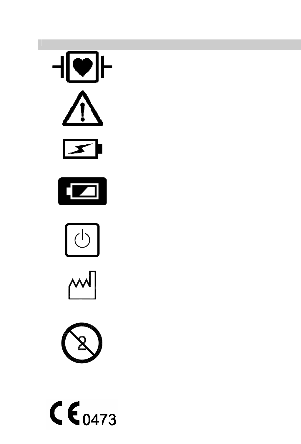
Tempus IC User/Operator Manual
14 Symbols Used on the Tempus IC
The following symbols are used on the Tempus IC:
Symbol Description
Defibrillation proof type CF applied part, The ECG electrodes
are floating from earth and meet the patient leakage current
requirements of EN60601-1:1990 Inc A13:1996 for type CF
applied parts. The ECG electrodes are proof against the effects
of a cardiac defibrillator discharge.
Attention, consult accompanying documents
Battery Charge indicator – flashes green when the battery is on
charge
Battery power level
System power on/off (push/push)
Date of manufacture, where the year that the item was
manufactured is represented by the year and then the month
e.g. 2002 06 is June 2002.
Single use device only, discard item after use
IPX5 The device is proof against a hose according to IEC529
The device has been declared by the manufacturer to be in
accordance with the requirements of the European Union
Medical Devices Directive 93/42/EEC as transposed by UK
national legislation.
YYYY - MM
Page 110 41-1001-00B
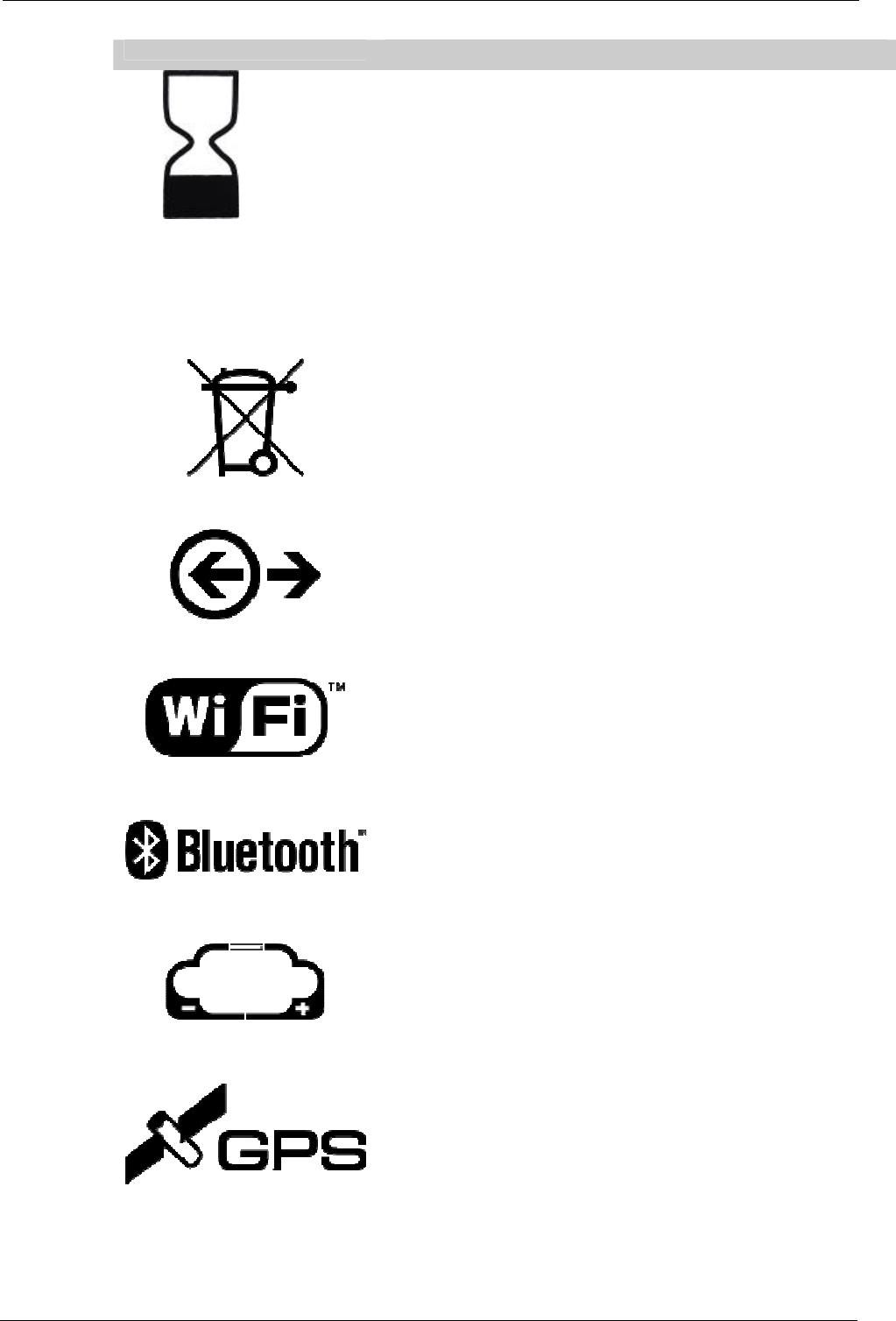
Tempus IC User/Operator Manual
Page 111 41-1001-00B
Symbol Description
Shelf life, where the time that the unit must be used by is
represented by the year and then the month e.g. 2004 06 is
June 2004.
LOT YYYY - MM
Where the year that the item was manufactured as a part of a
larger batch is represented by the year and then the month e.g.
2002 06 is June 2002.
This product should not be discarded as general waste and must
be disposed of as electrical and electronic waste.
Communications connections
WiFi connection mode to response centre
Bluetooth connection to medical modules
Battery Connection – to indicate positive terminal polarity
Global Positioning System (GPS) -
YYYY - MM
Tempus IC User/Operator Manual
Page 112 41-1001-00B
Symbol Description
Global System for Mobile (GSM) communications
Headset connector
Power Status (green indicates mains power is connected)
Camera Backlight
Device contains wireless transmitters
DC connector

Tempus IC User/Operator Manual
Page 113 41-1001-00B
15 Software License Agreements
This product incorporates software object code licensed by Remote Diagnostic Technologies Ltd. The software is licensed, not sold. All rights reserved. If
you do not agree to this End User License Agreement ("EULA"), do not use the device or copy the software. Instead, promptly contact Remote Diagnostic
Technologies Ltd for instructions on return of the unused device(s) for a refund. Any use of the software, including but not limited to use on the device, will
constitute your agreement to this EULA. The agreement: (i) prohibits any disassembly, decompilation, and/or reverse engineering or any other action
attempting to discover or disclose the source code or methods or concepts embodied in the source code; (ii) the software and chipset copyright, trademark
other proprietary notices and confidential legends shall not be altered; (iii) all warranties associated with the software object code shall be no greater than the
license agreement made between Remote Diagnostic Technologies Ltd and its licensor, (iv) the liability of the licensor shall be limited and shall be no greater
than that expressly set forth in the license agreement between Remote Diagnostic Technologies Ltd and the licensor.
END USER LICENSE AGREEMENT
You have acquired a device TEMPUS IC that includes software licensed by REMOTE DIAGNOSTIC TECHNOLOGIES LTD. from Microsoft Licensing Inc.
(MS) or its affiliates EURODIS BYTECH LIMITED. Those installed software products of MS origin, as well as associated media, printed materials, and
“online” or electronic documentation (“SOFTWARE”) are protected by international intellectual property laws and treaties. The SOFTWARE is licensed, not
sold. All rights reserved.
IF YOU DO NOT AGREE TO THIS END USER LICENSE AGREEMENT (“EULA”), DO NOT USE THE DEVICE OR COPY THE SOFTWARE. INSTEAD,
PROMPTLY CONTACT REMOTE DIAGNOSTIC TECHNOLOGIES LTD. FOR INSTRUCTIONS ON RETURN OF THE UNUSED DEVICE (S) FOR A
REFUND. ANY USE OF THE SOFTWARE, INCLUDING BUT NOT LIMITED TO USE ON THE DEVICE, WILL CONSTITUTE YOUR AGREEMENT TO
THIS EULA (OR RATIFICATION OF ANY PREVIOUS CONSENT).
GRANT OF SOFTWARE LICENSE. This EULA grants you the following license:
You may use the SOFTWARE only on the DEVICE.
NOT FAULT TOLERANT. THE SOFTWARE IS NOT FAULT TOLERANT. REMOTE DIAGNOSTIC TECHNOLOGIES LTD. HAS INDEPENDENTLY
DETERMINED HOW TO USE THE SOFTWARE IN THE DEVICE, AND MS HAS RELIED UPON REMOTE DIAGNOSTIC TECHNOLOGIES LTD. TO
CONDUCT SUFFICIENT TESTING TO DETERMINE THAT THE SOFTWARE IS SUITABLE FOR SUCH USE.
NO WARRANTIES FOR THE SOFTWARE. THE SOFTWARE is provided “AS IS” and with all faults. THE ENTIRE RISK AS TO SATISFACTORY
QUALITY, PERFORMANCE, ACCURACY, AND EFFORT (INCLUDING LACK OF NEGLIGENCE) IS WITH YOU. ALSO, THERE IS NO WARRANTY
AGAINST INTERFERENCE WITH YOUR ENJOYMENT OF THE SOFTWARE OR AGAINST INFRINGEMENT. IF YOU HAVE RECEIVED ANY
WARRANTIES REGARDING THE DEVICE OR THE SOFTWARE, THOSE WARRANTIES DO NOT ORIGINATE FROM, AND OR NOT BINDING ON, MS.
Note on Java Support. The SOFTWARE may contain support for programs written in Java. Java technology is not fault tolerant and is not designed,
manufactured, or intended for use or resale as online control equipment in hazardous environments requiring fail-safe performance, such as in the
operation of nuclear facilities, aircraft navigation or communications systems, air traffic control, direct life support machines, or weapons systems, in which the
failure of Java technology could lead directly to death, personal injury, or severe physical or environmental damage. Sun Microsystems, Inc. has contractually
obligated MS to make this disclaimer.
No liability for Certain Damages. EXCEPT AS PROHIBITED BY LAW, MS SHALL HAVE NO LIABILITY FOR ANY INDIRECT, SPECIAL,
CONSEQUENTIAL OR INCIDENTIAL DAMAGES ARISING FROM OR IN CONNECTION WITH THE USE OR PERFORMANCE OF THE SOFTWARE.
THIS LIMITATION SHALL APPLY EVEN IF ANY REMEDY FAILS OF ITS ESSENTIAL PURPOSE. IN NO EVENT SHALL MS BE LIABLE FOR ANY
AMOUNT IN EXCESS OF U.S. TWO HUNDRED FIFTY DOLLARS (U.S.$250.00).
Limitations on Reverse Engineering, Decompilation, and Disassembly. You may not reverse Engineer, decompile, or disassemble the SOFTWARE,
except and only to the extent that such activity is expressly permitted by applicable law notwithstanding this limitation.
SOFTWARE TRANSFER ALLOWED BUT WITH RESTRICTIONS. You may permanently transfer rights under this EULA only as part of a permanent sale or
transfer of the Device, and only if the recipient agrees to this EULA. If the SOFTWARE is an upgrade, any transfer must also include all prior versions of the
SOFTWARE.
EXPORT RESTRICTIONS. You acknowledge that SOFTWARE is of US-origin. You agree to comply with all applicable international and national laws that
apply to the SOFTWARE, including the U.S. Export Administration Regulations, as well as end-user, end-use and country destination restrictions issued by
U.S. and other governments. For additional information on exporting the SOFTWARE, see http://www.microsoft.com/exporting/