Remote Possibilities RBTX1A Remote Control Transmitter User Manual Basic 01 V1
Remote Possibilities LLC Remote Control Transmitter Basic 01 V1
Users Manual

by Remote Possibilities LLC
BASIC
-
01
-
MAN
Ver.0_2004
1212
Page
1
of
18
18
The RRemote Basic™ System
The RRemote Basic™ System is designed to provide a very small, yet high output, remote
control for model railroads. By stepping outside the traditional 27 & 75 MHz “box” we are able
to offer a compact modular design with the smallest transmitter in the industry.
Configurability
The RRemote Basic™ System offers great flexibility and configurability to meet a variety of
applications.
?? Add one or more BasicPWM™ drivers to the RRemote BasicRX™ to add direct motor
drive in 5 Amp increments.
?? Add a BasicServo™ driver to the RRemote BasicRX™ to control your live steam
locomotives.
?? Add a BasicRelay™ driver to the RRemote BasicRX™ to remotely control large (up to 3
Amp) loads, such as track switches.
?? Use the RRemote BasicRX™ without driver boards to remotely control small (<500 mA)
loads, such as lights.
Customization
Because the RRemote Basic™ System is so flexible, both standard and semi-custom firmware
is available to meet the needs of our customers. Special feature requests are welcome, and will
be accommodated on a “time available” basis.
Dimensions
The standard footprint for the RRemote BasicRX™, BasicPWM™, and BasicServo™*, and
BasicSound™* boards is 1 x 2 inches. The BasicRelay™ board, which is generally used at
trackside, is larger (approx 3 inches square).
by Remote Possibilities LLC
BASIC
-
01
-
MAN
Ver.0_2004
1212
Page
2
of
18
18
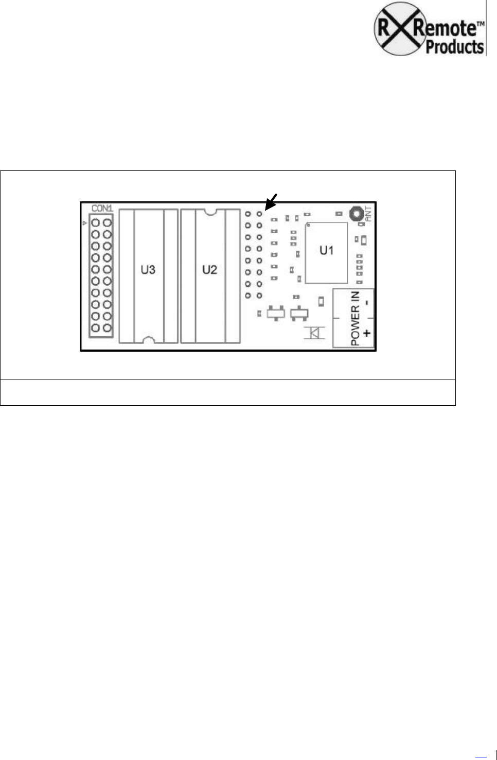
RRemote BasicRX™ Receiver Board
The RRemote Basic™ System is based on the RRemote Basic-RX1 Receiver Board (see
Figure 1 below). It contains a PIC chip (U1), Output Driver chip (U2), RF receiver (U3) and
Antenna Input (ANT), Interface Connector (CON1) and configuration jumpers (JUMPERS). The
MCU (microcontroller unit) and the Output Driver chips are socketed for easy upgrade and/or
replacement.
Figure 1 RRemote Basic™ Receiver layout (top view)
The RRemote Basic™ driver boards (BasicPWM™, BasicServo™, and BasicSound™) plug into
the 20-pin interface connector socket (CON1) on the Receiver board or the CON1 connector of
the next driver board in the “stack”.
The configuration jumpers set the receiver address, as well as selecting whether the locomotive
acts as a “leader” or a “follower” in MU lash-ups (see the following section titled “Jumpers” for
more information).
Power Input
Power from 6-28 VDC is supplied through the POWER IN screw terminals on the Receiver.
Although the RRemote Basic™ modules are polarity protected, the power leads will have to be
correctly connected for the system will operate. Power In terminal polarity is color coded on the
terminal block, RED for (+) and BLACK for (-) battery connections. The Receiver supplies
power to the driver module through the CON1 connector.
Important:
DO USE AN IN-LINE FUSE! We strongly recommend using an in-line fuse between the
battery and Receiver.
DO NOT REMOVE THE INSULATING STRIP LOCATED UNDER THE POWER INPUT
TERMINALS! This provides protection from short circuits.
Jumpers

by Remote Possibilities LLC
BASIC
-
01
-
MAN
Ver.0_2004
1212
Page
3
of
18
18
Antenna
The RRemote Basic™ Receiver is supplied with an antenna wire connected to the “ANT”
(Antenna) pad of the Receiver board. The ANT wire is long enough to allow flexibility in
installations, and coiled for compactness. The free end of the coil can be pulled to extend the
antenna. The ANT wire can be trimmed to length, but a minimum length of 3.25 inches should
be retained to assure a ¼ wavelength antenna. A vertical antenna will show less directionality,
but horizontal installations will also work fine at shorter ranges.
Jumpers
The Receiver address, as well as the whether the Receiver will function as a “lead” or “follower”
locomotive in a Multi-Unit (MU) lash-up, is set by means of jumpers. set the as well as the role
of the Receiver when operated as part of a Multi-Unit (MU) lash-up, are set
Address Jumpers
The address jumpers on the receiver board are labeled 1 through 6. 63 individual unit
addresses can be set, with unit address “00” reserved for secondary engines in MU consists
(see section titled “Multi-Unit Configuration” for more information). Unless otherwise requested
the address jumpers will be pre-set at the factory, with no configuration required for standard
operation.
Refer to the “Address Jumper Reference” at the end of this document for details on changing
Receiver/Transmitter address jumper settings.
The configuration jumpers can be fitted with a ribbon cable to allow the configuration jumpers to
be positioned in a convenient location and set with miniature DIP switches. This modification
would be useful if you find yourself changing jumper settings often. A Jumper Extension kit can
be ordered from www.rremote.com to make this easier.
Data Jumpers
The data jumpers are used to select whether the Receiver will output data as the “leader”
engine, or accept data from another Receiver as a “follower” engine in MU configurations.
When using the TX-1 Keyfob Transmitter all “follower” engines should be set to “00” (jumpers 1-
6 installed) to program the “follower” to accept commands from the “lead” engine.
The “leader” engine receives commands via it’s normal address and retransmits them tagged
with address “00” to the “followers” via the MU connection.
Aux Outputs
When activated each Aux Out provides a connection to electrical ground. This type of Aux Out
can drive circuits (headlamps, ditch lights, etc) and “masquerade” as a reed switch to directly
trigger sound units. The Aux Out can handle a single output load of 500 mA (milliamps), with a
1000 mA (1000mA = 1 Amp) total load for all Aux Outs combined.
The Auxiliary Outputs are connected via the Interface Connector CON1. An Aux Out ribbon
cable connector is supplied with the system to simplify making connections, with extras
available through www.rremote.com. Alternately, a 2mm pitch 20 contact pin header can be
by Remote Possibilities LLC
BASIC
-
01
-
MAN
Ver.0_2004
1212
Page
4
of
18
18
plugged into the CON1 connector, with individual wires soldered to the pins of the header to
connect Aux Outputs.
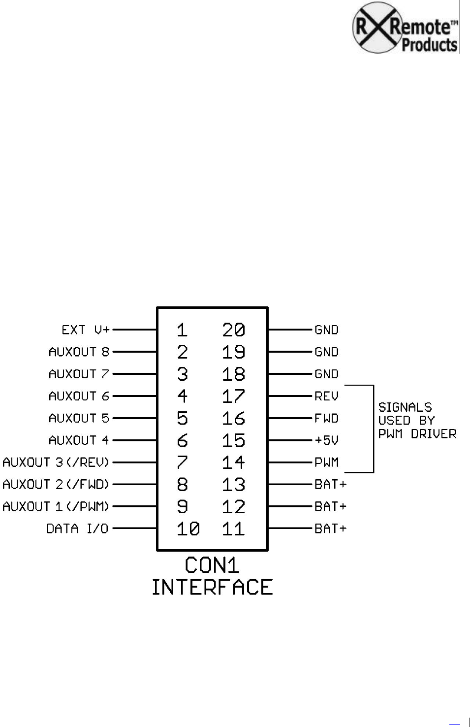
The full pin-out of the RRemote Basic™ CON1 connector is shown in Figure 2. Three of the
Aux Outs have fixed functions:
?? Aux Out 1 (pin 9) mirrors the PWM output signal to the motor driver. This signal can control
fire-box lighting.
?? Aux Out 2 (pin 8) will be set (grounded) when driving forward or at “zero speed”. This signal
gives directional lighting control for the headlight.
?? Aux Out 3 (pin 7) will be set (grounded) when driving in reverse. This signal gives
directional lighting control for reverse lighting.
?? Aux Out 7 and Aux Out 8 (pins 2 and 3) are operated by the LEFT and RIGHT buttons of the
BasicTX-1 transmitter.
Figure 2 CON1 Interface Connections (top view)

by Remote Possibilities LLC
BASIC
-
01
-
MAN
Ver.0_2004
1212
Page
5
of
18
18
Triggering Sound Boards
Aux Outputs 7 & 8 can be directly connected to the “trigger inputs” of most sound boards, and
perform just like a reed switch for this purpose. Remember to keep the grounds of the Receiver
and the sound board connected.
Aux Output Precautions
The following precautions must be followed to avoid damage to the Aux Output Driver chip and
to the RRemote Basic Receiver board as a whole:
a) The power supply for external Aux Out loads must be less than 36 VDC
b) The ground (-) terminal of the RRemote Basic™ POWER IN connector MUST be
connected to the ground (-) terminal of the power supply of the external load to provide
common grounding, and
c) A maximum of 1000 mA (1 amp) can be controlled by the Aux Output Driver chip, and
exceeding 500 mA through any one Aux Output will result in damage.
d) If connecting a relay, motor or any other inductive type load, CON1 pin 9 MUST be
connected to the positive (+) terminal of the supply voltage for the Aux Out. It is advised
that an external “snubber” (diode or RC network) be installed across the load to prevent
damage to the Output Driver chip (from “inductive kickback” or “back-EMF spike”).
Output Driver Chip Damage
A damaged Aux Output Driver chip (labeled U2 on the underside of the board) will usually show
one or more of the following symptoms:
?? outputs won’t set
?? outputs are stuck “on” and won’t unset
?? the chip gets hot and releases all of its “magic smoke”
The usual cause of any of these problems is exceeding the current or voltage limits of the Aux
Outputs, or getting a “spike” from an inductive load (motor, solenoid, relay, etc) without a
snubber. Remember to always follow the precautions listed under “Aux Output Precautions”.
The Output Driver chip is easily replaced following the procedure in “Replacing Chips”.
Replacement Output Driver chips (ULN2803A) are available either through www.rremote.com or
an electronics distributor of your choice. The Output Driver chip should only be replaced after
you have identified and fixed the cause of the damage, disconnected the offending load, or
determined that the chip just died of its own volition.
PIC Chip Swaps
The PIC chip (labeled U1 on the underside of the board) controls the operation of the Receiver
board. If you request customized features for your Receiver, upgrade your system to the
Enhanced transmitter, or wish to change the role of the Receiver (e.g. changing from on-board
throttle to controlling a Relay Driver board) you will need to swap out the PIC chip. Follow the
procedure in “Replacing Chips”.
by Remote Possibilities LLC
BASIC
-
01
-
MAN
Ver.0_2004
1212
Page
6
of
18
18
It is very unlikely that the PIC chip will ever fail under normal use. Symptoms of this would
include complete non-function of the Receiver, or the PIC chip getting very hot, releasing “magic
smoke”, etc. If the PIC chip becomes suspect it is recommended that the Receiver be returned
for evaluation and service, since it is likely that a non-socketed component caused the failure.
Replacing Chips
Both the Aux Output Driver and PIC chips are socketed on the RRemote Basic Receiver board.
Should the Aux Output Driver chip become damaged or you need to swap out the PIC chip to
upgrade your system, follow the procedure below:
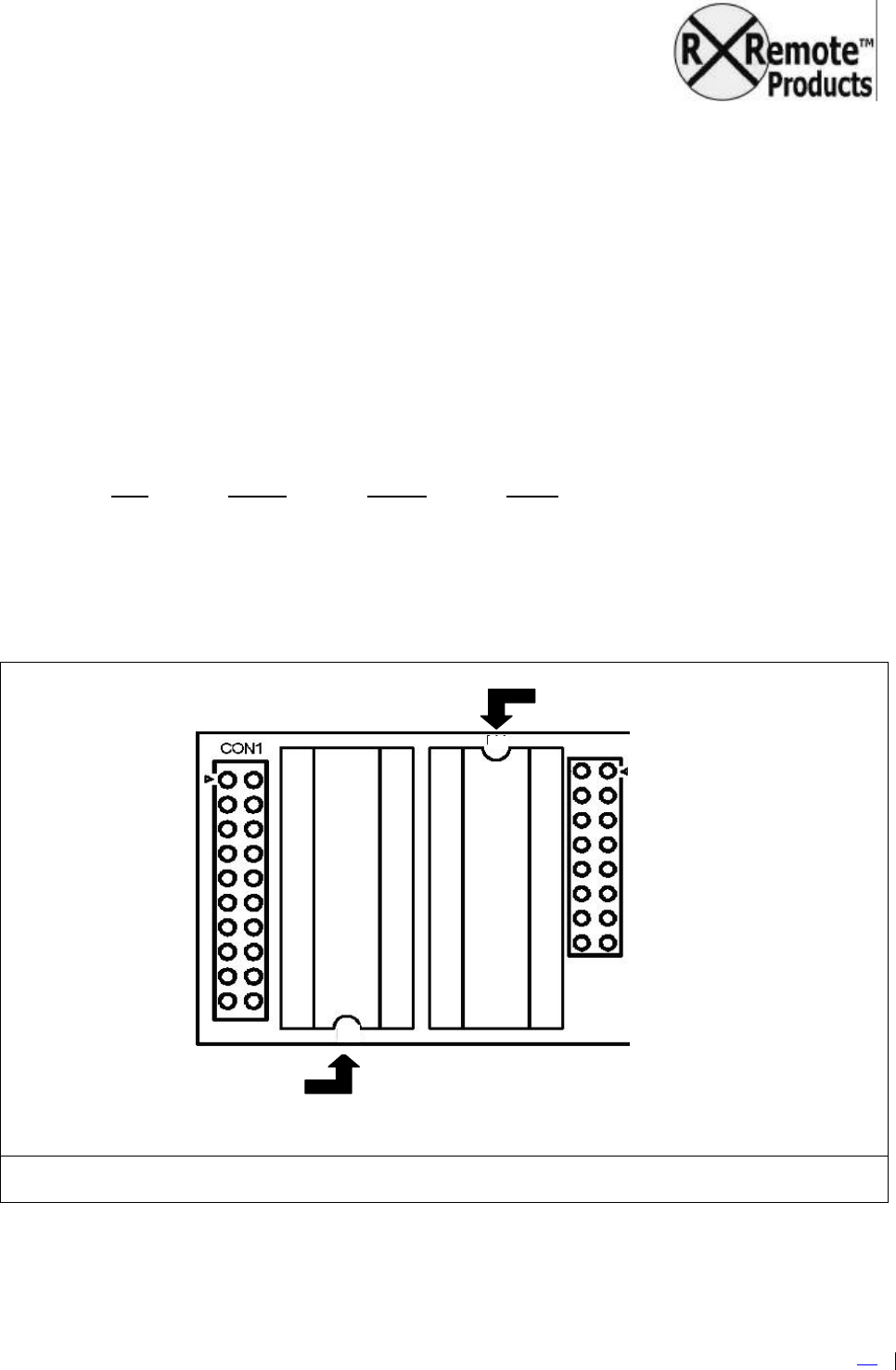
1. Note the orientation of the chip to be replaced. Each chip had a “dimple” at one end.
The dimple on the Output Driver will be at the opposite side of the receiver board as the
dimple end of the PIC chip. See Figure 3.
2. Lift the old chip from its socket by sliding the tip of a small flat blade screwdriver between
the chip and the socket (not the socket and the board, since this will permanently
damage the receiver board).
3. Insert the new chip orientated the same as old chip. It is usually easier to get all the pins
on one side of the chip started into the socket, then press against the far side of the chip
to guide the remaining pins into the socket. Once you have all pins aligned and started
into the socket, press down on the chip to seat it firmly. Verify that all pins are in the
socket and no pins are bent.
Figure 3 Aux Out Driver Chip Orientation (top view)
“Dimple end” of
the
Aux Output Driver chip
“Dimple end” of
the PIC chip
by Remote Possibilities LLC
BASIC
-
01
-
MAN
Ver.0_2004
1212
Page
7
of
18
18
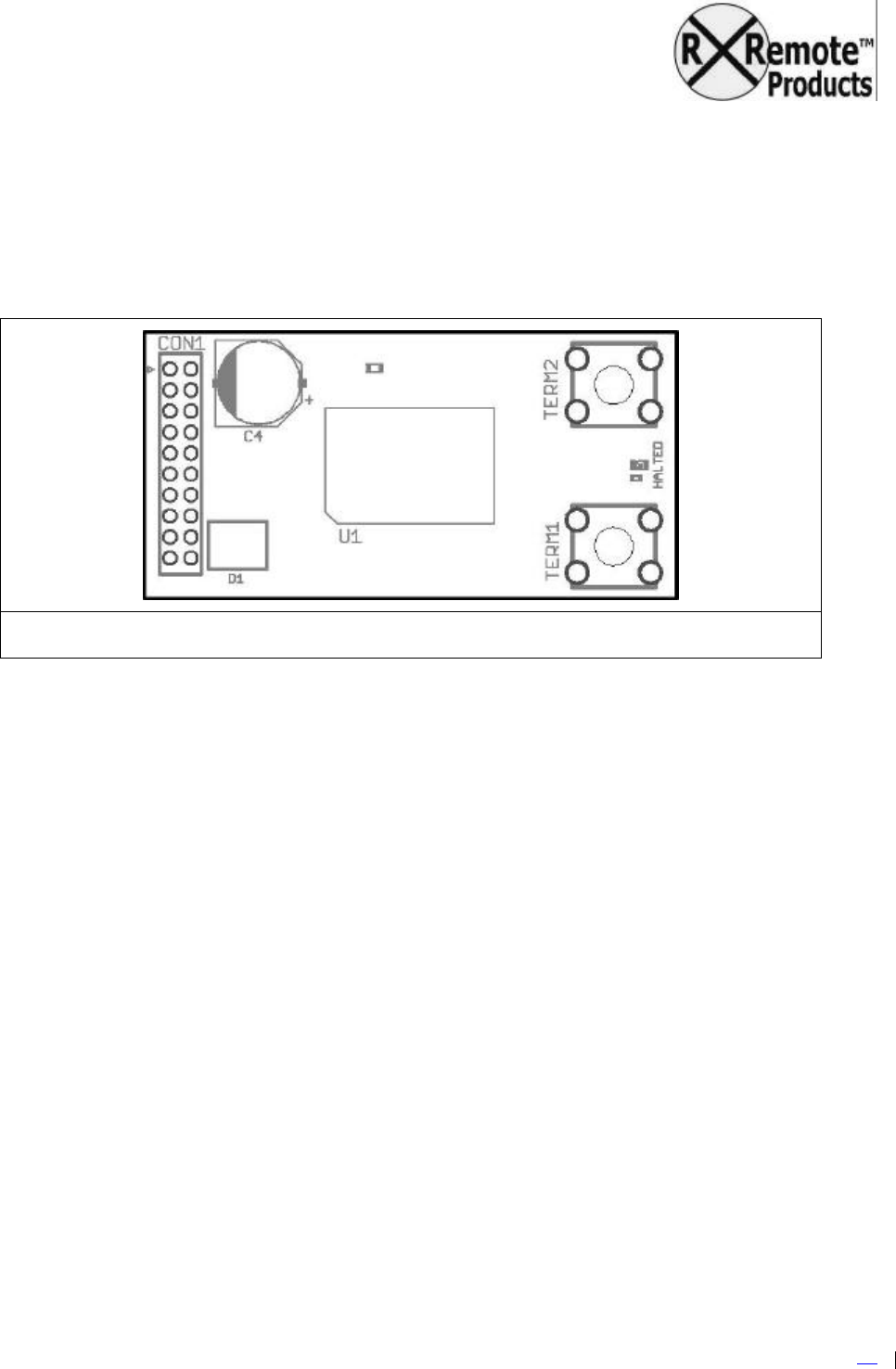
RRemote BasicPWM™ Motor Driver
The BasicPWM™ Driver supplies PWM (Pulse Width Modulation) motor drive output from 0-
100% duty cycle. The maximum sustained current output of the BasicPWM™ is 5 Amps. The
BasicPWM™ Driver layout is shown in Figure 2 below. The major BasicPWM™ components
are the Interface Connector (CON1), Driver IC (U1), Logic IC (U2), Protection Diode (D1) and
Motor Output terminals.
Figure 4 RRemote BasicPWM™ Driver layout (top view)
CON1 plugs directly to CON1 of the BasicRX™ Receiver or the CON1 of another BasicPWM
driver. CON1 carries power and control signals from the BasicRX™ Receiver.
The Driver IC (U1) controls the actual motor voltage. The Logic IC (U2) performs directional
switching control. Voltage Regulator (VR1) supplies +5 volts for the Logic IC. Protection Diode
(D1) is a special low drop diode that blocks power should the POWER IN wires be reversed.
The BasicPWM™ driver is the major heat source in the RRemote Basic™ System. The
BasicPWM™ can become very hot under heavy loads (175°C = 350° Fahrenheit thermal
shutdown temperature), so exercise caution. See the section titled “Dealing With Heat” for more
information.
Should excessive current or high temperature be detected the BasicPWM driver will shut down
and the red “HALTED” LED between to the output screw terminals will be lighted.
by Remote Possibilities LLC
BASIC
-
01
-
MAN
Ver.0_2004
1212
Page
8
of
18
18
Installation On-board
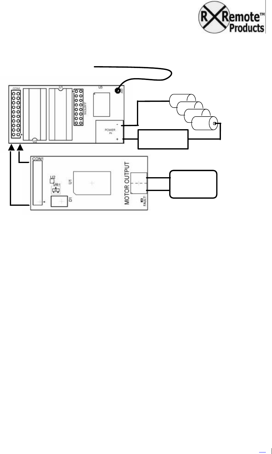
Figure 5 RRemote Basic™ Installation Connections
1. Access the motor leads of your locomotive, and isolate them from the track power
pickups. (Leaving the track pickups connected to the motor leads will cause the
RRemote to supply power to the rails). A switch may be installed to select between
track power or battery power (see section titled “Wiring Diagrams”).
2. Mount the Receiver “stack” (Receiver + Driver/s). Pick a spot for the Receiver stack
that:
1) Addresses heat dissipation as discussed previously.
2) Allows wire runs for the motor and battery (terminals will accept up to 16
AWG solid wire, with 22 AWG the recommended minimum), Aux Out leads
and antenna wire,
3) Affords reasonable access. If you plan to transfer your RRemote Basic™
from train to train, try to make it easy on yourself.
3. Attach the motor leads to the motor terminals of the RRemote BasicPWM™ driver(s).
4. Attach battery leads to the battery terminals of the RRemote BasicRX™.
5. Carefully mate the CON1 connectors of the Receiver and the Driver.
+
-
In
-
line fuse
MANDATORY!
MOTOR(S)
BATTERY
PACK
ANTENNA WIRE

by Remote Possibilities LLC
BASIC
-
01
-
MAN
Ver.0_2004
1212
Page
9
of
18
18
6. Before buttoning up your loco or tender, test for excessive heating and proper motor
direction. Apply power to the Receiver stack, then press and hold the forward command
button of the transmitter for 10 seconds. Check:
a) there is not excessive heating (from a mis-wire, excessive loading, etc)
b) the direction of rotation of the wheels. If the wheels are turning backward in
response to the forward command, remove power and reverse the motor leads
7. Once you have confirmed the safe and correct operation of the receiver you can
reassemble the car.
8. Installation is complete.
For light-duty or temporary mounting, a small amount of 3M Outdoor Mounting Tape (available
at most home improvement stores) is attached to the bottom of both the Receiver and
BasicPWM driver boards. It sticks well to most any clean dry surface, provides electrical
insulation, and is just the right width. Remove the red plastic backing to attach the Receiver. If
you re-apply 3M Outdoor Mounting Tape just use a little bit at either end of the Receiver stack: if
you use too much you might not be able to pry the Receiver loose again.
For heavy duty mounting, the BasicPWM has two holes for #2 screws. Care should be taken
when mounting the Driver to avoid shorting the output terminals or the CON1 connector area.
In the near future www.rremote.com will offer polymer heat-sink pads (conduct heat but not
electricity) to make the heatsink mounting process easier.
Dealing with Heat
Planning for heat dissipation is important. The RRemote Basic can generate heat just like any
other remote control/throttle unit, so think about what kind of load you will be pulling when
planning your installation.
Automatic thermal shutdown will happen when the internal temperature of the motor driver
reaches 175 degrees C. This will light the “HALTED” LED on the PWM driver board. If this
happens often you have a heat problem, and need to think about adding a heat-sink.
Heavy loads require the use of a heat-sink to help move heat away from the driver. . The idea
is to spread the heat out over a larger area and let air carry it away. Heat sinks come in many
forms: finned, CPU-type heatsink/cooling fan combinations, or just a piece of sheet metal.
How far can your car can go with the exhaust pipe plugged? A heatsink is like an exhaust pipe,
and the heat has to be able to get out of the heat-sink for it to do you any good. Air flow is the
escape route for this heat.
by Remote Possibilities LLC
BASIC
-
01
-
MAN
Ver.0_2004
1212
Page
10
of
18
18
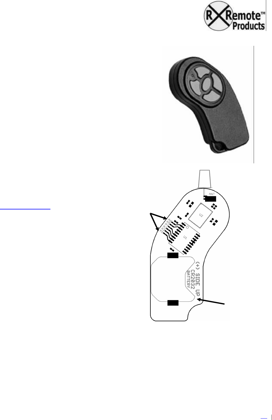
RRemote BasicTX-01™
The RRemote BasicTX-01™ is a miniature keyfob-style
transmitter for controlling the RRemote Basic™ system.
Battery
RRemote BasicTX-01™ uses a number of techniques to
prolong the life of its battery. Under normal use you
should expect to see a battery life of 2 months. Should
the “transmit LED” grow noticeably dimmer, you
experience delay or difficulty in getting the receiver to
respond to commands, or if the voltage falls to 2.7 volts
or less (measured in circuit with no command being
send), you need to REPLACE THE TRANSMITTER
BATTERY.
The CR2032 (or equivalent) 3 volt
lithium coin cell is available at many
home improvement, drug, or electronic
retailers. Replacements are also
available directly from
www.rremote.com at minimal cost.
The RRemote BasicTX-01™ is
designed to operate only with this
battery and voltage, and applying a
higher voltage will permanently
damage the transmitter (really, it will).
Receiver/Transmitter
Address
The address traces in the transmitter
are located on the back (battery) side.
They are labeled A1 through A6, and
consist of two small rectangular pads
connected by a narrow copper
“jumper” line. An intact strip reads as
a ‘0’, a cut trace reads as a ‘1’. Table1
in the Receiver section provides a
reference for setting the address
jumpers on both the Transmitter and
Receiver.
In most cases you will not need to change the address in either the Transmitter or Receiver as
they will come pre-set to matching values.
Address traces
Battery clip
RRemote Basic TX-01 address traces
and battery clip (inside back view)
by Remote Possibilities LLC
BASIC
-
01
-
MAN
Ver.0_2004
1212
Page
11
of
18
18
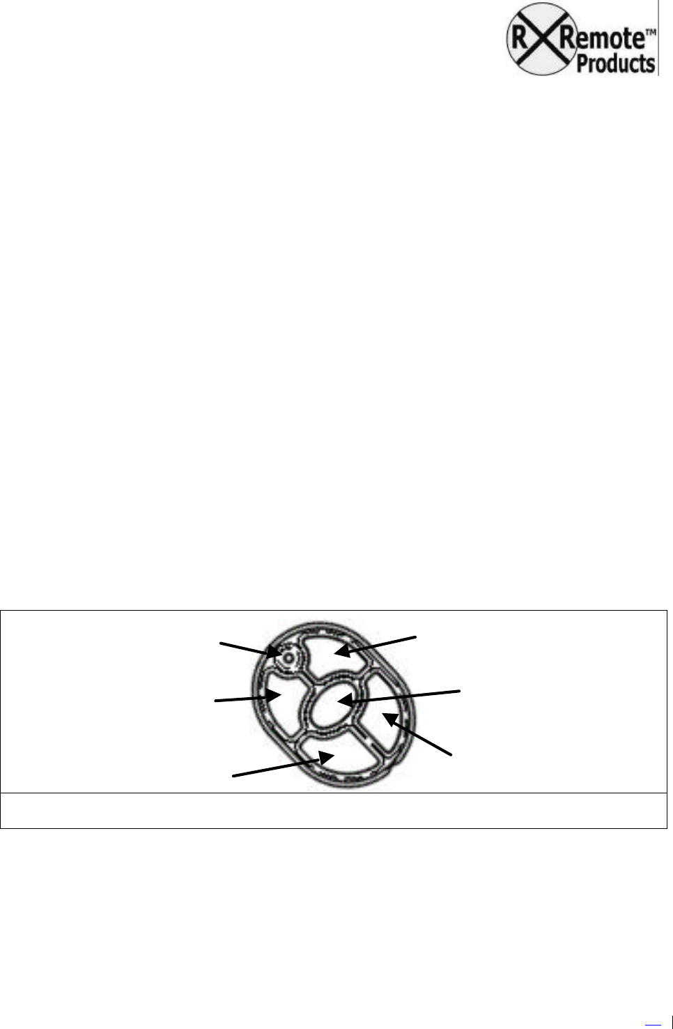
Quick Start Guide
Okay, so you’ve installed the receiver. Now how do you use the thing? Here’s the “short
course”:
?? Apply power to the receiver. Plug in the battery pack and/or turn on the power switch
(user option).
?? Smooth forward, stop and reverse transitions can be obtained using the
FORWARD and REVERSE buttons. With the train moving forward, holding the
REVERSE button will slow the train to a halt, then start it moving in reverse. Reverse
speed will increase toward the maximum for as long as you hold the REVERSE button.
Likewise, with the train moving in reverse, holding the FORWARD key will slow the train
to a halt, then start it moving forward. Forward speed will increase toward the maximum
for as long as you hold the FORWARD button.
o Press the FORWARD button to increase the forward speed, or slow the
reverse speed. Press the FORWARD button to ramp-up the forward speed.
o Press the REVERSE button to slow the forward speed, or increase the
reverse speed. Press the REVERSE button to ramp-down the forward speed or
increase the reverse speed.
?? Press the STOP button to stop quickly. The speed will rapidly fall to zero.
?? Aux Outputs:
a. Pressing the LEFT button will set the output at CON1 pin 2 for as long as the
button stays pressed.
b. Pressing the RIGHT button will set the output at CON1 pin 3 for as long as the
button stays pressed.
Figure 6 TX-1 Keypad
FORWARD
REVERSE
LEFT AUX
RIGHT AUX
TRANSMIT LED
STOP

by Remote Possibilities LLC
BASIC
-
01
-
MAN
Ver.0_2004
1212
Page
12
of
18
18
RRemote Basic™ Relay Driver
The RRemote Basic™ Relay Driver provides 8 DPDT relays with 5 Amp outputs suitable for
control of switch motors, solenoid-type track switches, lighting, or other accessories.
Configured for “make/break” duty each relay can switch 10 Amps, and when configured for
“reversing” duty each relay can switch 5 Amps.
The 5 Amp 8 relay board measures approximately 2 ¾ inches square.
Release date: TBA
RRemote Basic™ Servo Driver
The RRemote Basic™ Servo Driver provides up to 4 servo outputs for control of ‘live steam’ or
accessories.
Release date: TBA.

by Remote Possibilities LLC
BASIC
-
01
-
MAN
Ver.0_2004
1212
Page
13
of
18
18
Wiring Diagrams
& Jumper Appendix
by Remote Possibilities LLC
BASIC
-
01
-
MAN
Ve
r.0_20041212
Page
14
of
18
18
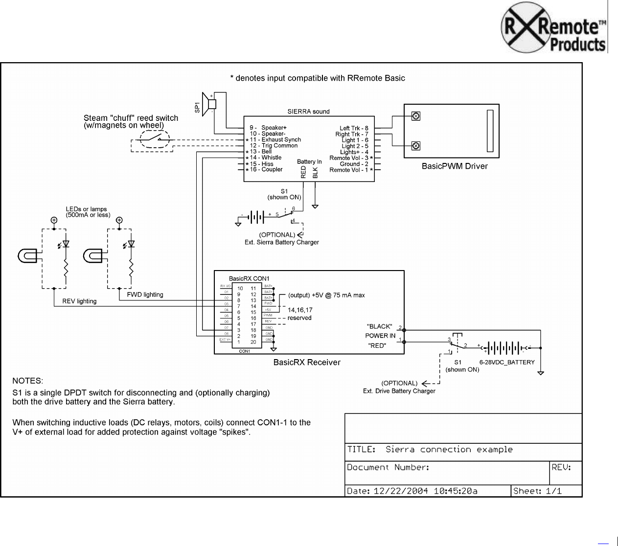
Sample connection diagram using the Soundtraxx Sierra™ sound system
by Remote Possibilities LLC
BASIC
-
01
-
MAN
Ve
r.0_20041212
Page
15
of
18
18
Sample connection diagram using the Phoenix Big Sound 2K2™ sound system
Diagram TBD
by Remote Possibilities LLC
BASIC
-
01
-
MAN
Ve
r.0_20041212
Page
16
of
18
18
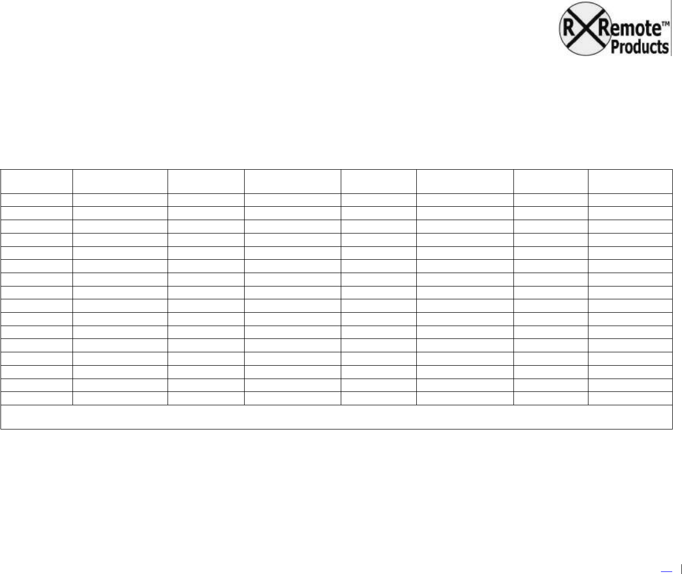
Address Jumper Reference
The Receiver and Transmitter address jumpers must match exactly, since the receiver will only process commands from a
transmitter with a matching address. Should you ever need to change the address jumpers, refer to Table 1 below for a breakdown
of possible address jumper combinations.
Table 1 – Unit Address to Jumper Settings
Unit
Address Jumper
654321 Unit
Address Jumper
654321 Unit
Address Jumper
654321 Unit
Address Jumper
654321
00 111111 16 101111 32 011111 48 001111
01 111110 17 101110 33 011110 49 001110
02 111101 18 101101 34 011101 50 001101
03 111100 19 101100 35 011100 51 001100
04 111011 20 101011 36 011011 52 001011
05 111010 21 101010 37 011010 53 001010
06 111001 22 101001 38 011001 54 001001
07 111000 23 101000 39 011000 55 001000
08 110111 24 100111 40 010111 56 000111
09 110110 25 100110 41 010110 57 000110
10 110101 26 100101 42 010101 58 000101
11 110100 27 100100 43 010100 59 000100
12 110011 28 100011 44 010011 60 000011
13 110010 29 100010 45 010010 61 000010
14 110001 30 100001 46 010001 62 000001
15 110000 31 100000 47 010000 63 000000
Unit Address is the “human readable” number corresponding to the code set on Jumpers 1 through 6
1 = Jumper, 0 = No Jumper

by Remote Possibilities LLC
BASIC
-
01
-
MAN
Ver.0_200
50114
Page
17
of
18
18
Regulatory Notices
& Information Appendix

by Remote Possibilities LLC
BASIC
-
01
-
MAN
Ver.0_200
50114
Page
18
of
18
18
FCC Required Notices:
This device complies with Part 15 of the FCC rules. Operation is subject to the following two
conditions:
?? this device may not cause harmful interference, and
?? this device must accept any interference received, including that may cause undesired
operation.
Changes or modifications to this equipment could void the user's authority to operate the
equipment.
NOTE: This equipment has been tested and found to comply with the limits for a Class B digital
device, pursuant to Part 15 of the FCC Rules. These limits are designed to provide reasonable
protection against harmful interference in a residential installation.
This equipment generates, uses and can radiate radio frequency energy and, if not installed and
used in accordance with the instructions, may cause harmful interference to radio communications.
However, there is no guarantee that interference will not occur in a particular installation.
If this equipment does cause harmful interference to radio or television reception, which can be
determined by turning the equipment off and on, the user is encouraged to try to correct the
interference by one or more of the following measures:
-- Reorient or relocate the receiving antenna.
-- Increase the separation between the equipment and receiver.
--Connect the equipment into an outlet on a circuit different from that to which the
receiver is connected.
--Consult the dealer or an experienced radio/TV technician for help.
IC Required Notices:
The term "IC:" before the radio certification number only signifies that Industry Canada technical
specifications were met.
This device has been designated to operate with an antenna having a maximum gain of 1 dB. An
antenna having a higher gain is strictly prohibited per regulations of Industry Canada. The required
antenna impedance is 50 ohms.
The installer of this radio equipment must insure that the antenna is located or pointed such that it
does not emit RF field in excess of Health Canada limits for the general population; consult Safety
Code 6, obtainable from Health Canada.
Equipment Identification:
FCC ID: SVARBTX1A
IC ID: 5630ARBTX1A