Remotec Technology BW8030US Zwave Thermostat User Manual
Remotec Technology Limited Zwave Thermostat
UserManual.wiki
>
Remotec Technology
>
BW8030US User Manual
>
user manual
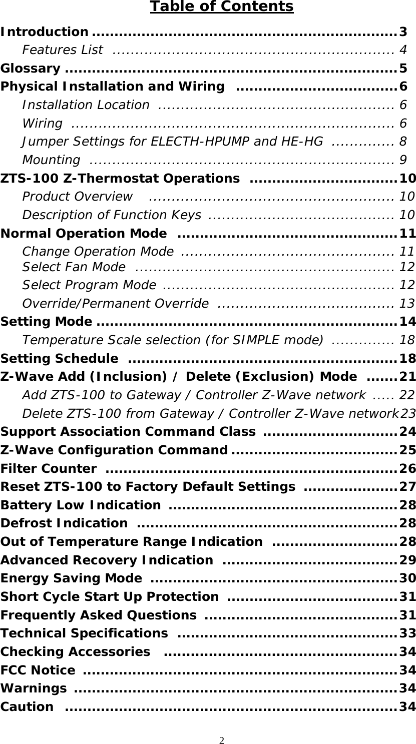
Contents
1.
user manual
2.
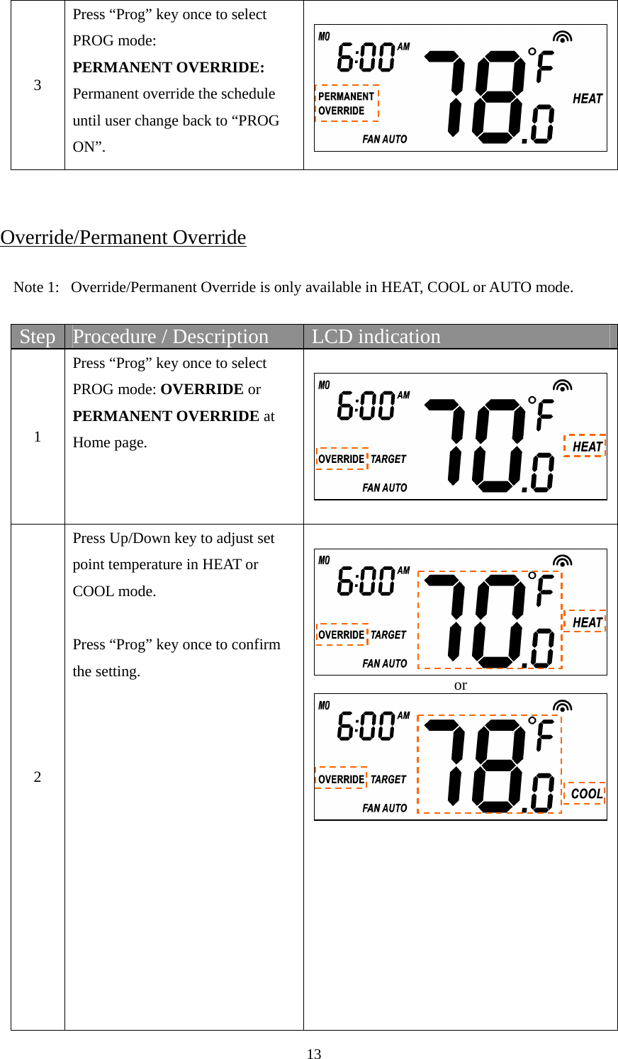
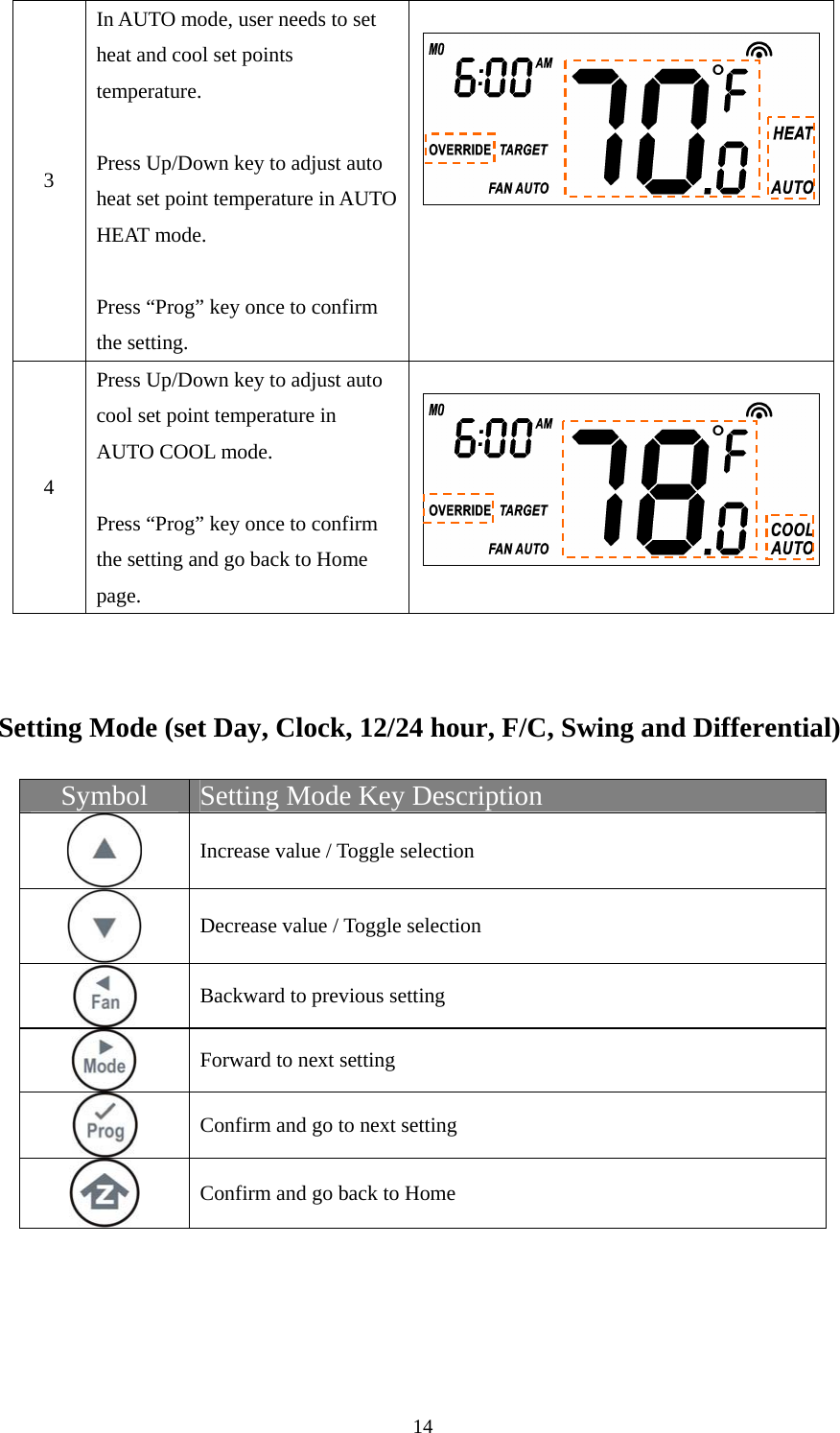
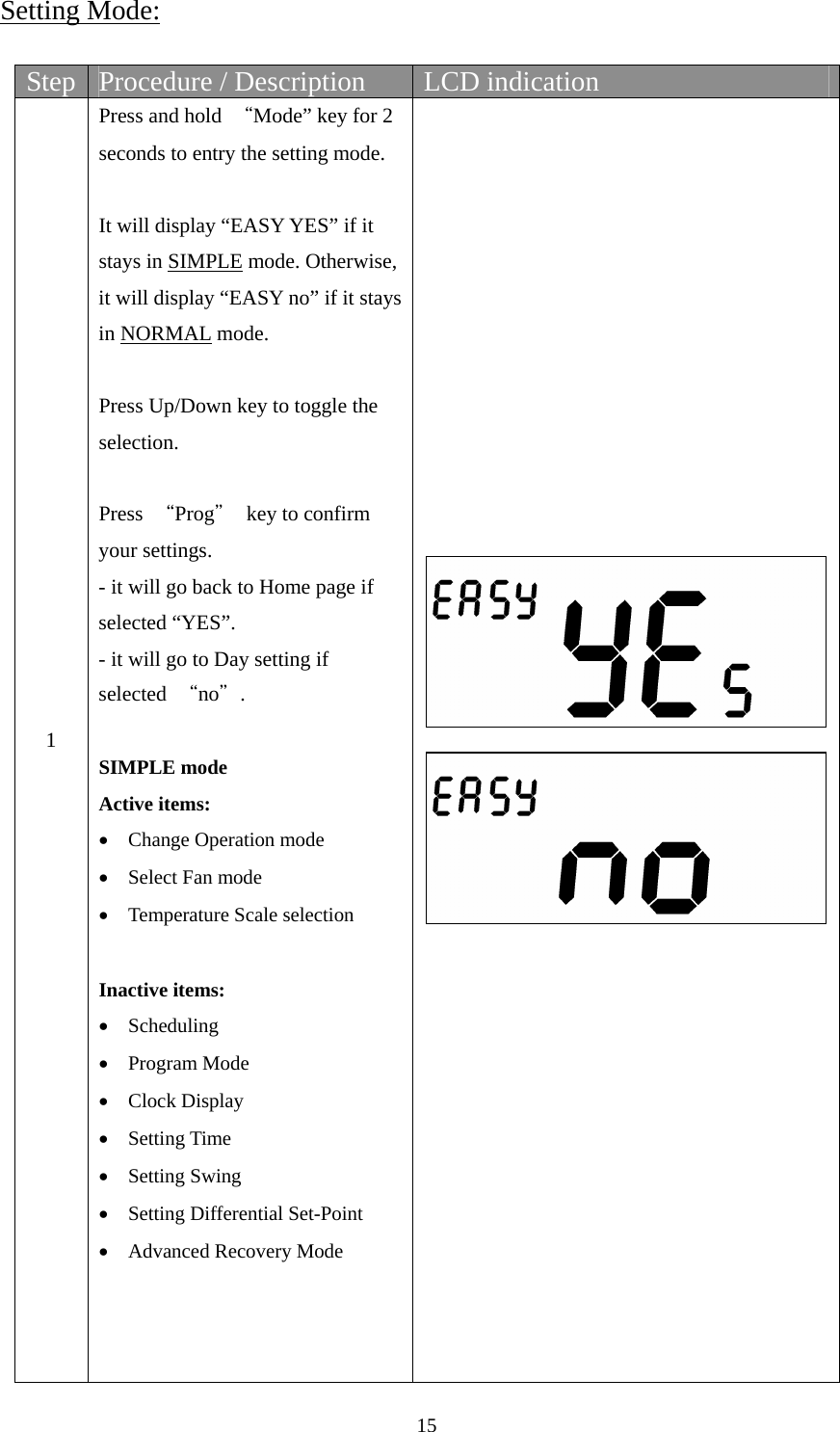
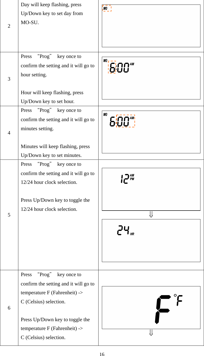
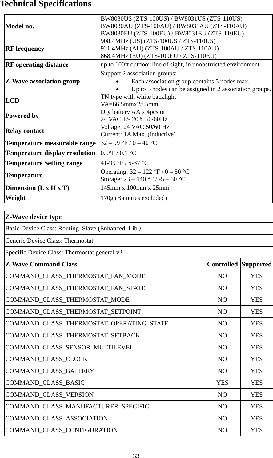
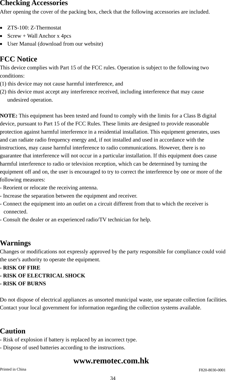
User Manual
user manual
Navigation menu
Upload a User Manual
Namespaces
Wiki Guide
HTML
PDF
Info
Views
User Manual
Discussion / Help
Navigation