Remotec Technology BW8030US Zwave Thermostat User Manual
Remotec Technology Limited Zwave Thermostat
Contents
- 1. user manual
- 2. User Manual
user manual
1
ZTS-100 / ZTS-110
(Z-Thermostat)

2
Table of Contents
Introduction ....................................................................3
Features List .............................................................. 4
Glossary ..........................................................................5
Physical Installation and Wiring ....................................6
Installation Location .................................................... 6
Wiring ....................................................................... 6
Jumper Settings for ELECTH-HPUMP and HE-HG .............. 8
Mounting ................................................................... 9
ZTS-100 Z-Thermostat Operations .................................10
Product Overview ...................................................... 10
Description of Function Keys ......................................... 10
Normal Operation Mode .................................................11
Change Operation Mode ............................................... 11
Select Fan Mode ......................................................... 12
Select Program Mode ................................................... 12
Override/Permanent Override ....................................... 13
Setting Mode ...................................................................14
Temperature Scale selection (for SIMPLE mode) .............. 18
Setting Schedule ............................................................18
Z-Wave Add (Inclusion) / Delete (Exclusion) Mode .......21
Add ZTS-100 to Gateway / Controller Z-Wave network ..... 22
Delete ZTS-100 from Gateway / Controller Z-Wave network 23
Support Association Command Class ..............................24
Z-Wave Configuration Command .....................................25
Filter Counter .................................................................26
Reset ZTS-100 to Factory Default Settings .....................27
Battery Low Indication ...................................................28
Defrost Indication ..........................................................28
Out of Temperature Range Indication ............................28
Advanced Recovery Indication .......................................29
Energy Saving Mode .......................................................30
Short Cycle Start Up Protection ......................................31
Frequently Asked Questions ...........................................31
Technical Specifications .................................................33
Checking Accessories ....................................................34
FCC Notice ......................................................................34
Warnings ........................................................................34
Caution ..........................................................................34
3
ZTS-100 / ZTS-110 Z-Thermostat
Introduction
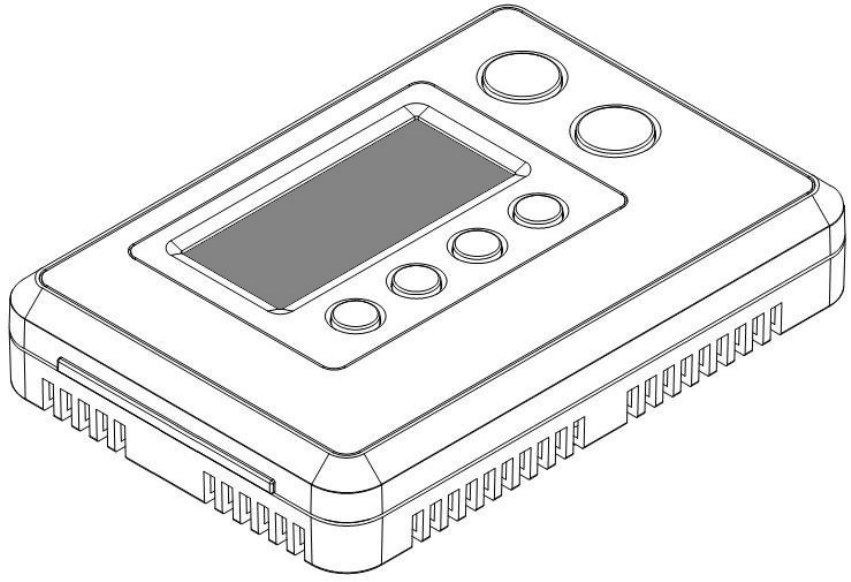
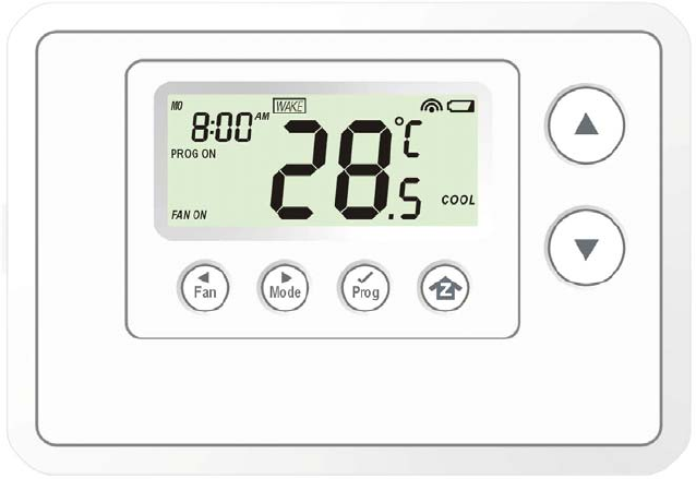
Welcome to the Z-Wave world of home automation, your ZTS-100 Z-Thermostat (Figure 1) is a
comfort control master that allows to control your room temperature with programmable time
schedule WAKE, AWAY, HOME and SLEEP event which can maximize energy conservation and
comfort while minimizing the effort required to maintain the appropriate temperature in your home
whether you are at home or away.
Also, it can be utilized to control / check your room temperature by the smart phone or PC while you
are at office, home anywhere or around the world which can go through the Z-Wave gateway
control.
ZTS-100 can be configured as either “Frequently Listening Routing Slaves” (FLiRS) or “Always
Listening” node and it will distinguish the power source (batteries or 24Vac) automatically and
switch to appropriate mode during inclusion stage.
FLiRS node type is targeted for battery operated applications and will enter sleep mode frequently in
order to conserve battery consumption that can provide flexibility if there is out of 24Vac power line.
Always Listening node type is targeted for AC power operated applications and it can act as a
repeater, which will re-transmit the RF signal to ensure that the signal is received by its intended
destination by routing the signal around obstacle and radio dead spots.
Figure 1. ZTS-100 / ZTS-110
4
Features List
HVAC System Type Compatible:
z Standard (gas/electric) or Heat Pump
Multistage System Compatible:
z Standard HVAC Systems: 2 stage heating, 1 stage cooling
z Heat Pump Systems: 2 stage heating, 1 stage cooling
Heat Pump change over valve:
z Selectable change over with cool or with heat
Power:
z Powered by alkaline batteries AA x 4pcs or 24Vac
Program Style:
z 2 program modes for scheduling (Mo-Fr, Sa-Su)
z 4 Separate Time and Temperature Settings for each program
z Heat and Cool set-points for each program
z Temporary Program Override
z Permanent Program Override
z Built-in flash memory stores heat and cool program settings
Temperature Display and Control:
z Temperature display in °F or °C
z Temperature Measurable Range: 32 – 99 °F / 0 – 40 °C
z Temperature Setting Range: 41-99 °F / 5-37 °C
z Adjustable Temperature Control Swing/Differential
a) Swing: 1°F, 2°F, 3°F or 4°F ( 0.5°C, 1.0°C, 1.5°C or 2°C)
b) Differential: 1°F, 2°F, 3°F or 4°F ( 0.5°C, 1.0°C, 1.5°C or 2°C)
z Advanced Recovery Mode (ARM)
z Defrost Function
z Short cycle start up protection
Clock:
z Time display format: 12/24 hour clock selection with day displayed
Filter Counter:
z Filter change reminder displayed after 500 hours usage (500-4000hrs)
Others:
z Support Network Wide Inclusion (NWI) and Explore Frames
z Support “Frequently Listening Routing Slaves” (FLiRS) or “Always Listening”
z Support Simple mode
z Battery Low Indicator
z Built-in white LCD Backlight

5
Glossary
Device or Node
Devices and nodes are all terms to describe an individual Z-Wave
device. These are all interchangeable when setting up your Z-Wave
network.
Inclusion Add a Z-Wave device to the network.
Exclusion Delete a Z-Wave device from the network.
Remove To take a device out of a group, scene or association group while
that device still exists in the same Z-Wave network.
Network Wide Inclusion
(NWI)
Network Wide Inclusion (NWI) enables both end-user friendly,
Plug and Play like Z-Wave network installation as well as
professional installation scenario where the inclusion process in
terms of time will be reduced significantly. NWI is a feature
supported by a new frame type named Explorer which enables the
Z-Wave protocol to implement Adaptive Source Routing.
Z-Wave Network
A collection of Z-Wave devices is controlled by primary and
secondary controllers operating on the same system. A Z-Wave
network has its own unique ID code so that controllers not in the
network cannot control the system.
Primary Controller
The first controller is used to set up your devices and network. Only
the Primary Controller can be used to include or delete devices
from a network. It is recommended that you mark the primary
controller for each network for ease in modifying your network.
Secondary Controller
A controller containing network information about other devices
within the network and is used for controlling devices. Secondary
controller is created from the Primary Controller and cannot include
or delete devices to the network.
Inclusion Controller
A controller containing network information about other devices
within the network and is used for controlling devices. Inclusion
controller is created from the Primary Controller in a SIS enabled
Z-Wave network. Inclusion Controller has the ability to add and
remove devices from the network.
Scene
A collection of Z-Wave devices configured to turn to a specific
level, setting, mode, or perform an operation. Scenes are usually
activated by a controller, timed event, or specific conditions.
Association
Association is used to organize nodes in different groups allowing
the device to identify the nodes by a group identifier. The groups
can also be copied to other devices.
6
Physical Installation and Wiring
L CAUTION
− Read the enclosed instructions carefully before installing your new Z-Thermostat. Pay close
attention to all warnings and notes and carefully follow the installation steps in the order they
are presented to save time and minimize the risk of damaging the thermostat or the system it
controls.
− Turn off ZTS-100 and the electronic devices (e.g. heater, cooler) which will be connected and
the electric source before installation and maintenance. It is highly recommended that the
installation procedure is processed by trained personnel.
Battery safety!
− Use new batteries of the recommended type and size only.
− Never mix used and new batteries together.
− To avoid chemical leaks, remove batteries from the ZTS-100 if you do not intend to use the
unit for an extended period of time.
− Dispose of used batteries properly; do not burn or bury them.
Installation Location:
The Thermostat is restricted to be used in indoor only. It should be mounted on an inner wall about
1.5m above the floor at a position where it is readily affected by changes of the general room
temperature with freely circulating air. Avoid mounting above or near hot surfaces or equipment (e.g.
TV, heater, refrigerator). Avoid mounting where it will be exposed to direct sunshine, drafts, or in a
laundry room or other enclosed space. Do not expose this unit to dripping or splashing.
Wiring:
z Be sure the operation mode is OFF and Fan selection is Fan Auto
z Wire the proper cables at the terminal block according to the circuit diagram
z Afterward, push all cables back into the wall
z Do not use metal conduit or of cable provided with a metal sheath
z Recommends adding fuse or protective device in the line circuit
Terminals Symbol
Cool changeover (heat pump) O
Heat changeover (heat pump) B
2nd Stage heater W2
1st Stage heater W1
Fan G
Compressor Y
24Vac Power for Cooling RC
24Vac Power for Heating RH
24Vac Common C
7
Important!
The ZTS-100 can be powered by alkaline batteries AA x 4pcs or 24Vac.
Connect the “24Vac Common” (typically the black wire/terminal) and “24Vac Power” (typically the
Red wire/terminal) from the HVAC system to the ZTS-100 HVAC System terminal block “C” and
“RH” or “RC” terminals (the RH and RC terminals are default tied together).
Common or Split Transformer Systems:
Most HVAC systems have a common heating and cooling transformer. A wire is connected to tie the
RH and RC inputs together for this configuration. If you have a system with separate heating and
cooling transformers, you will need to disconnect the RH and RC wire.
When wiring split systems, wire the heating systems “24Vac Power” (red wire) to the ZTS-100
“RH” terminal, and wire the cooling systems “24Vac Power” to the ZTS-100 “RC” terminal. Also
wire the cooling systems “24Vac Common” to the ZTS-100 “C” terminals.
Note: Do not split RC/RH for Heat Pump systems!
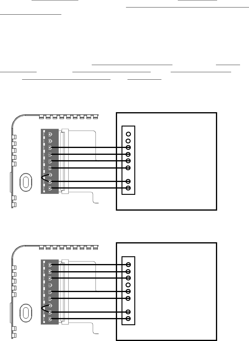
Figure 2. Non-heat pump (Standard Gas or Electric) HVAC system wiring
Figure 3. Heat pump system wiring
O
B
W2
W1
G
Y
RC
RH
C C - 24Vac Common
R - 24Vac Power
Y - Compressor
G - Fan
W1 – 1st stage heater
W2 – 2nd stage heater
Black
Red
Yellow
Green
White
Brown
Standard HVAC System
O
B
W2
W1
G
Y
RC
RH
C C - 24Vac Common
R - 24Vac Power
Y - Compressor
G - Fan
W2 – 2nd stage heater
Black
Red
Yellow
Green
Brown
O - Cool changeover (heat pump)
Heat Pump HVAC System
ZTS-100
B - Heat changeover (heat pump)
Blue
Orange
8
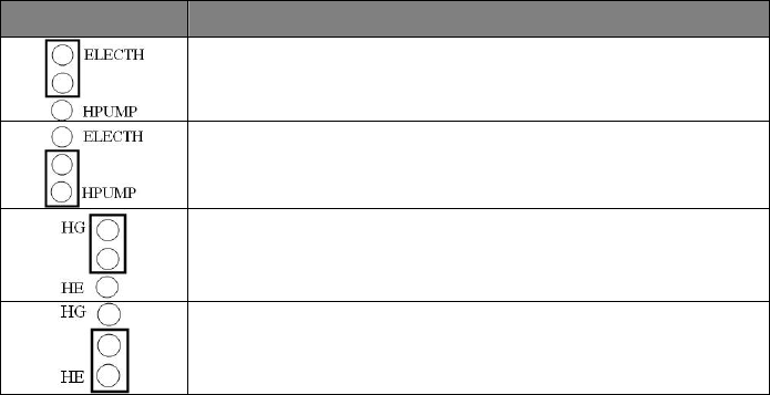
Jumper Settings for ELECTH-HPUMP and HE-HG:
Jumper Function Description
Set to ELECTH for non heat pump system (Default)
Set to HPUMP for heat pump system
Set to HG for Gas heat-fan controlled unit (Default)
Set to HE for Electrical heat-fan controlled unit
9
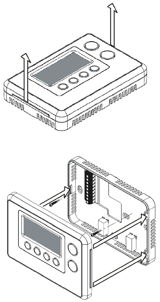
Mounting:
1. Open the ZTS-100 by pushing the hook (Figure 5)
2. Install AAx4pcs batteries if using battery power (Alkaline batteries are recommended)
3. Check the polarity of the batteries and the "+/-" marks inside the battery compartment
4. Connect 24Vac power if using 24Vac power source
5. Place the cables at the hole near the terminal block
6. Insert 2 pieces of wall anchors into the holes of the wall
7. Fasten the thermostat with 2 pieces of long screws through the 2 mounting holes (Figure 6)
8. Install the top housing by hooking the bottom (Figure 6)
Figure 5. Open ZTS-100
Figure 6. Install the top housing
10
ZTS-100 Z-Thermostat Operations
The following section will guide you through the set up processes for your ZTS-100.
Different listening nodes are able to act as repeaters to enlarge the network range.
Please note that all Z-Wave thermostat controllers are designed and manufactured by various
vendors whom are compatible with your ZTS-100 as long as they carry the Z-Wave logo:
(Please carefully read through the following then store the manual for future reference.)
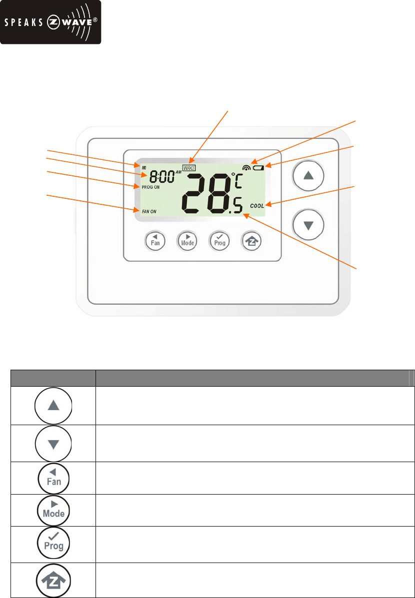
Product Overview
Figure 7. ZTS-100 / ZTS-110
Description of Function Keys
Symbol Key Description
Increase value / Toggle selection
Decrease value / Toggle selection
Select fan mode; also the Backward function key in some menus
Change operation mode; also the Forward function key in some menus
Select program mode:
PROG ON, OVERRIDE and PERMANENT OVERRIDE;
also the Confirm function key in some menus
Back to Home
Battery low indication
Mode
Program mode
Fan mode
Time
Day
Inclusion indication
Event mode
Current temperature
11
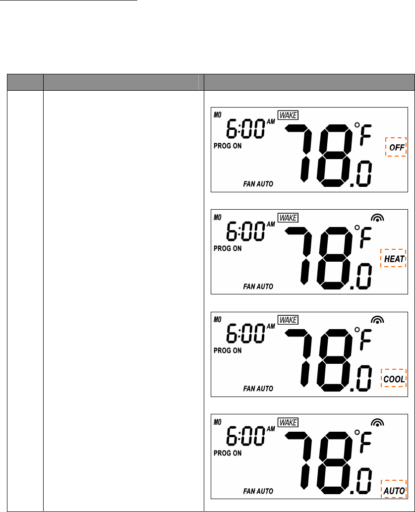
Normal Operation Mode
Change Operation Mode
Note 1: In Heat mode => it displays “HEAT” if ELECTH is selected.
=> it displays “HEAT PUMP” if HPUMP is selected.
Step Procedure / Description LCD indication
1
Press “Mode” key once to change
the operation mode:
OFF -> HEAT (PUMP) -> COOL
-> AUTO -> OFF
⇓
⇓
⇓
12
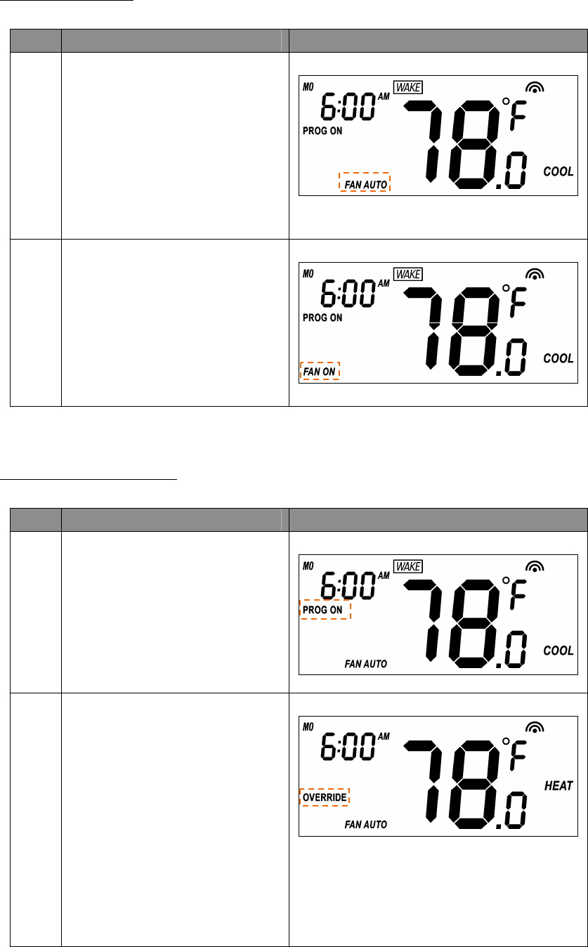
Select Fan Mode
Step Procedure / Description LCD indication
1
Press “Fan” key once to change the
Fan mode:
FAN AUTO -> FAN ON
FAN AUTO:
Electric heat (HE): Fan runs only
when Heating/Cooling is running.
Gas heat (HG): Fan runs only when
Cooling is running.
2
Press “Fan” key once to change the
Fan mode:
FAN ON:
Fan stays on all the time.
Select Program Mode:
Step Procedure / Description LCD indication
1
Press “Prog” key once to select
PROG mode:
PROG ON -> OVERRIDE
->PERMANENT OVERRIDE
PROG ON: Run the schedule.
2
Press “Prog” key once to select
PROG mode:
OVERRIDE: Temporary override
the current schedule and will go
back to “PROG ON” when next
time schedule reach.
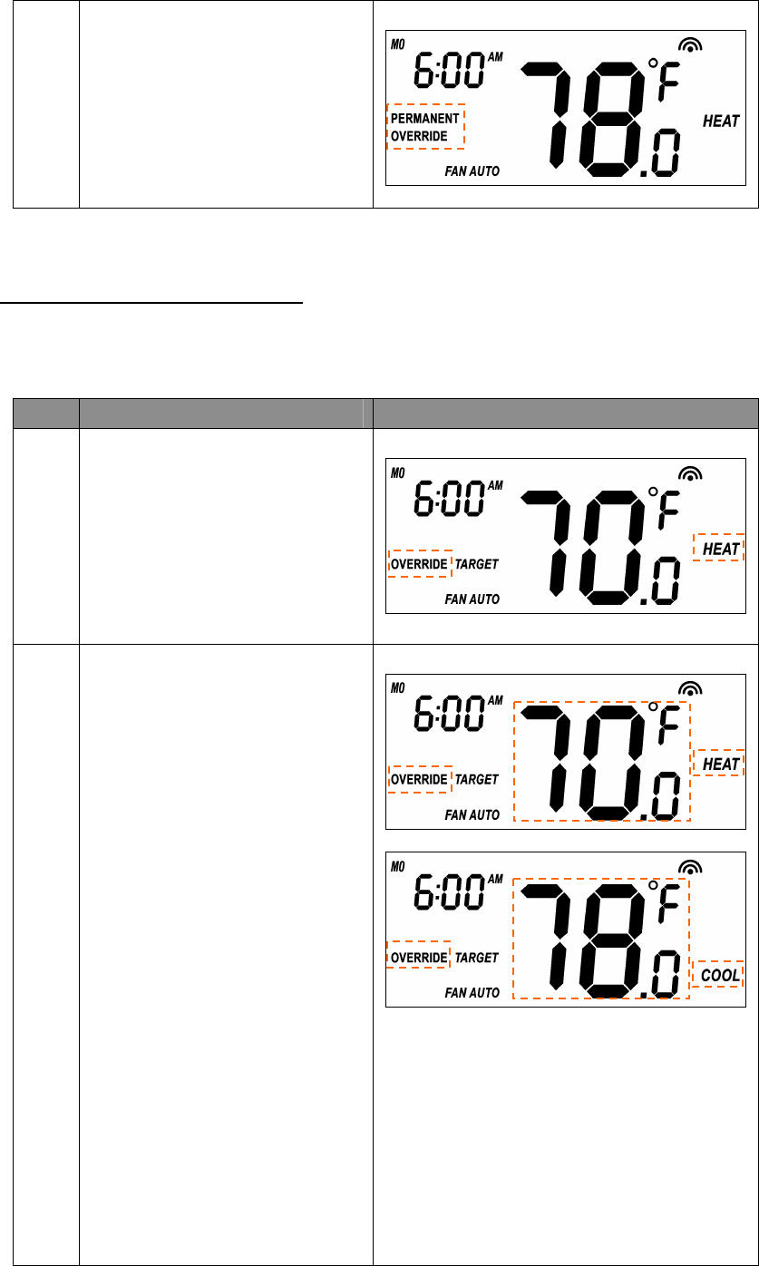
13
3
Press “Prog” key once to select
PROG mode:
PERMANENT OVERRIDE:
Permanent override the schedule
until user change back to “PROG
ON”.
Override/Permanent Override
Note 1: Override/Permanent Override is only available in HEAT, COOL or AUTO mode.
Step Procedure / Description LCD indication
1
Press “Prog” key once to select
PROG mode: OVERRIDE or
PERMANENT OVERRIDE at
Home page.
2
Press Up/Down key to adjust set
point temperature in HEAT or
COOL mode.
Press “Prog” key once to confirm
the setting.
or
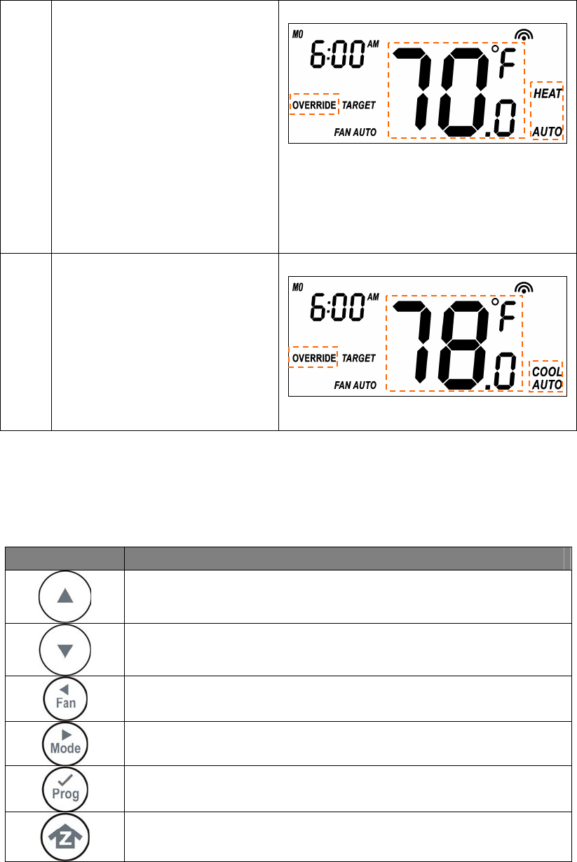
14
3
In AUTO mode, user needs to set
heat and cool set points
temperature.
Press Up/Down key to adjust auto
heat set point temperature in AUTO
HEAT mode.
Press “Prog” key once to confirm
the setting.
4
Press Up/Down key to adjust auto
cool set point temperature in
AUTO COOL mode.
Press “Prog” key once to confirm
the setting and go back to Home
page.
Setting Mode (set Day, Clock, 12/24 hour, F/C, Swing and Differential)
Symbol Setting Mode Key Description
Increase value / Toggle selection
Decrease value / Toggle selection
Backward to previous setting
Forward to next setting
Confirm and go to next setting
Confirm and go back to Home
15
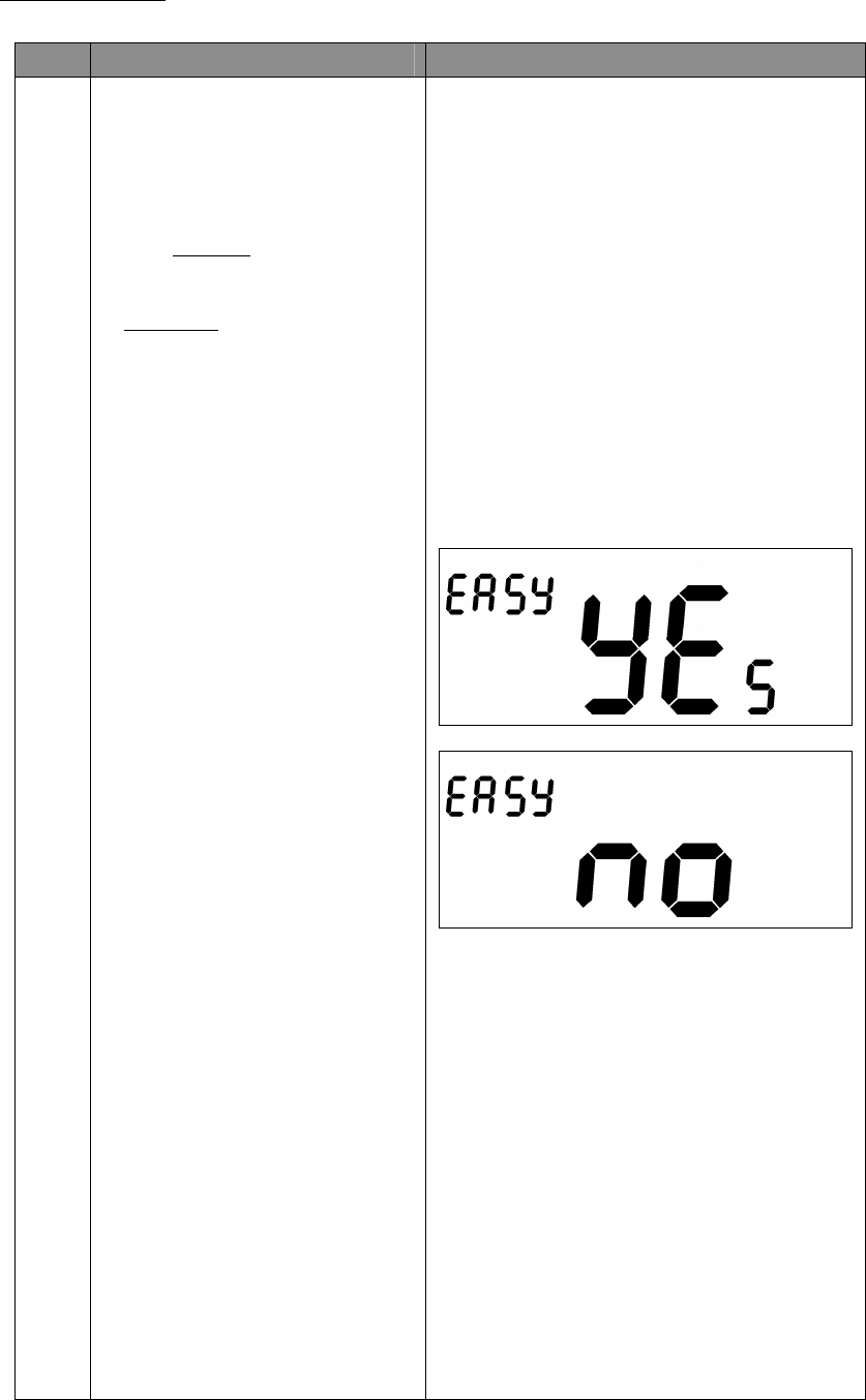
Setting Mode:
Step Procedure / Description LCD indication
1
Press and hold “Mode” key for 2
seconds to entry the setting mode.
It will display “EASY YES” if it
stays in SIMPLE mode. Otherwise,
it will display “EASY no” if it stays
in NORMAL mode.
Press Up/Down key to toggle the
selection.
Press “Prog" key to confirm
your settings.
- it will go back to Home page if
selected “YES”.
- it will go to Day setting if
selected “no".
SIMPLE mode
Active items:
• Change Operation mode
• Select Fan mode
• Temperature Scale selection
Inactive items:
• Scheduling
• Program Mode
• Clock Display
• Setting Time
• Setting Swing
• Setting Differential Set-Point
• Advanced Recovery Mode
16
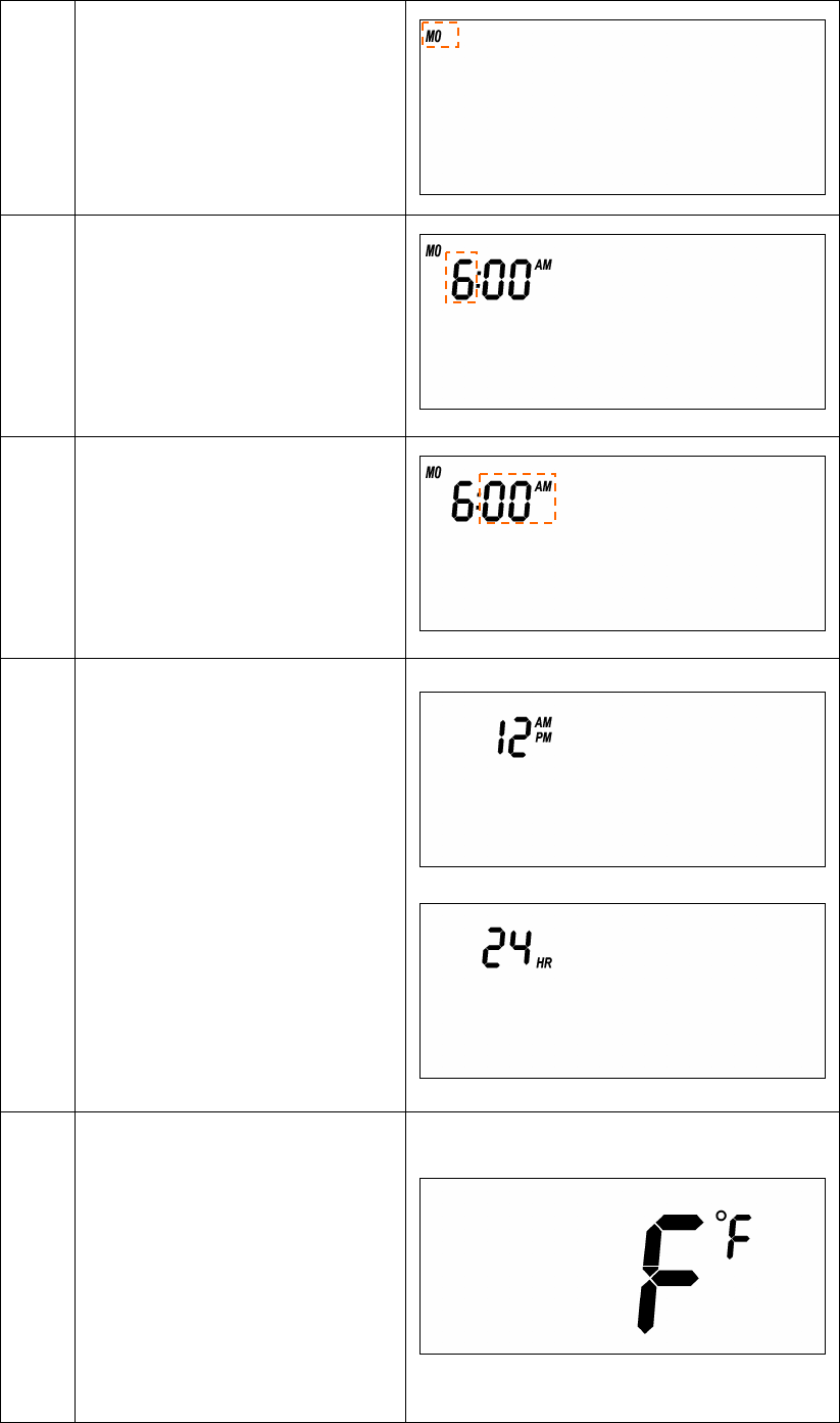
2
Day will keep flashing, press
Up/Down key to set day from
MO-SU.
3
Press “Prog" key once to
confirm the setting and it will go to
hour setting.
Hour will keep flashing, press
Up/Down key to set hour.
4
Press “Prog" key once to
confirm the setting and it will go to
minutes setting.
Minutes will keep flashing, press
Up/Down key to set minutes.
5
Press “Prog" key once to
confirm the setting and it will go to
12/24 hour clock selection.
Press Up/Down key to toggle the
12/24 hour clock selection.
⇓
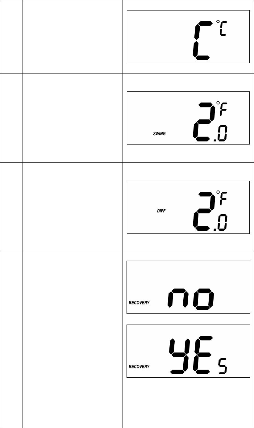
6
Press “Prog" key once to
confirm the setting and it will go to
temperature F (Fahrenheit) ->
C (Celsius) selection.
Press Up/Down key to toggle the
temperature F (Fahrenheit) ->
C (Celsius) selection.
⇓
17
7
Press “Prog" key once to
confirm the setting and it will go to
swing setting.
Press Up/Down key to set the
swing setting.
(Range is from 0.5oC to 2oC or
1oF to 4oF )
8
Press “Prog" key once to
confirm the setting and it will go to
differential set point setting.
Press Up/Down key to set the
differential set point setting.
(Range is from 0.5oC to 2oC or
1oF to 4oF )
9
Press “Prog" key once to
confirm the setting and it will go to
Advanced Recovery setting.
Press Up/Down key to
enable/disable Advanced Recovery
Mode.
⇓
18
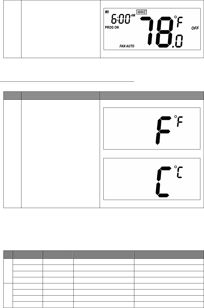
10
Press “Prog" key once to
confirm the setting and it will go to
the Home page.
Temperature Scale selection (for SIMPLE mode)
Step Procedure / Description LCD indication
1
Press and hold “Prog" keys for
2 seconds to entry temperature F
(Fahrenheit) -> C (Celsius)
selection.
Press Up/Down key to toggle the
temperature F (Fahrenheit) ->
C (Celsius) selection.
Press “Prog" key to confirm it
and back to the Home page.
⇓
Setting Schedule
Default Schedule:
Event Time Heat Cool
WAKE 6:00 AM 70 °F (21°C) 78 °F (26°C)
AWAY 8:00 AM 62 °F (17°C) 85 °F (29°C)
HOME 6:00 PM 70 °F (21°C) 78 °F (26°C)
MO – FR
SLEEP 10:00 PM 62 °F (17°C) 82 °F (28°C)
WAKE 6:00 AM 70 °F (21°C) 78 °F (26°C)
AWAY 10:00 AM 62 °F (17°C) 85 °F (29°C)
HOME 6:00 PM 70 °F (21°C) 78 °F (26°C)
SA – SU
SLEEP 11:00 PM 62 °F (17°C) 82 °F (28°C)
19
Step Procedure / Description LCD indication
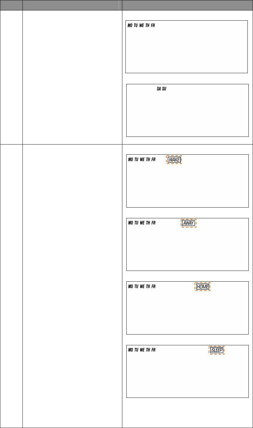
1
Press and hold “Prog ” key for 2
seconds to entry the setting
schedule mode.
Press Up/Down key to select
MO-FR or SA-SU schedule.
⇓
2
Press “Prog" key once to
confirm the setting and it will go to
event mode.
Press Up/Down key to select the
event (WAKE -> AWAY -> HOME
-> SLEEP).
⇓
⇓
⇓
20
3
Press “Prog" key once to
confirm the setting and it will go to
hour setting.
Hour will keep flashing, press
Up/Down key to set hour.
4
Press “Prog" key once to
confirm the setting and it will go to
minutes setting.
Minutes will keep flashing, press
Up/Down key to set minutes.
5
Press and hold “UP” and “DOWN”
key for 2 seconds to disable /
enable event during the time
setting.
If the event is disabled, “OFF” will
be displayed.
If the event is enabled, time will be
displayed and Hour will keep
flashing.
⇓
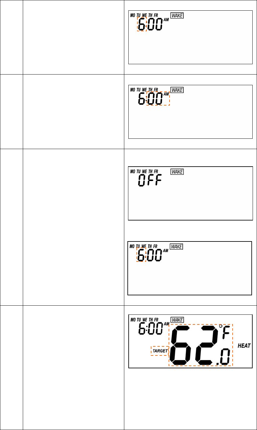
6
Press “Prog" key once to
confirm the setting and it will go to
target setting.
If the event is enabled, it will go to
target setting.
Target will keep flashing, press
Up/Down key to adjust Heat set
point for heating.
21
If the event is disabled, it will go to
next event setting.
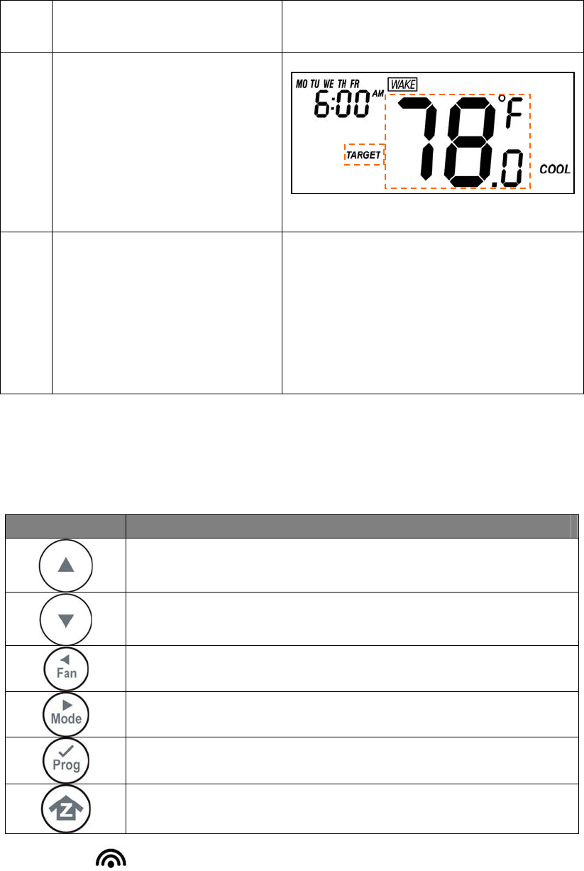
7
Press “Prog" key once to
confirm the setting and it will go to
target setting.
Target will keep flashing, press
Up/Down key to adjust Cool set
point for cooling.
8
Press “Prog" key once to
confirm the setting and it will go to
next event mode.
Follow the program UI to complete
the whole scheduling or press
Home key once to save and exit.
-
Z-Wave Add (Inclusion) / Delete (Exclusion) Mode
Symbol Inclusion and Exclusion Mode Key Description
N/A
N/A
N/A
N/A
Add (Inclusion) / Delete (Exclusion)
Back to Home
Note 1: This icon is represent the ZTS-100 has been added into the Z-Wave network.
Please perform the Delete (Exclusion) before adding into the new Z-Wave network.
Note 2: User can control the ZTS-100 through gateway or controller after adding into the Z-Wave
network.
22
ZTS-100 can be configured as either “Frequently Listening Routing Slaves” (FLiRS) or “Always
Listening” node and it will distinguish the power source (batteries or 24Vac) automatically and
switch to appropriate mode during inclusion stage.
FLiRS node type is targeted for battery operated applications and will enter sleep mode frequently in
order to conserve battery consumption that can provide flexibility if there is out of 24Vac power line.
Always Listening node type is targeted for AC power operated applications and it can act as a
repeater, which will re-transmit the RF signal to ensure that the signal is received by its intended
destination by routing the signal around obstacle and radio dead spots.
Application for out of 24Vac power line:
1. Install AAx4pcs batteries and power up the unit.
2. Execute the step of “Delete (Exclusion) ZTS-100 from Gateway / Controller Z-Wave network”.
3. Execute the step of “Add (Inclusion) ZTS-100 to Gateway / Controller Z-Wave network”.
4. ZTS-100 will be configured as FLiRS operation after step 3 (inclusion).
ZTS-100 will not response Z-Wave command very quickly as it will enter sleep mode
frequently in order to conserve battery consumption.
Application for 24Vac power line:
1. Connect 24Vac power and power up the unit, make sure AAx4pcs batteries has been removed.
2. Execute the step of “Delete (Exclusion) ZTS-100 from Gateway / Controller Z-Wave network”.
3. Execute the step of “Add (Inclusion) ZTS-100 to Gateway / Controller Z-Wave network”.
4. ZTS-100 will be configured as Always Listening operation after step 3 (inclusion).
It can install AAx4pcs batteries for power backup purpose after step 4.
Important:
It is not allow changing ZTS-100 operation mode by change of power source. It is need to follow
the above steps to change ZTS-100 operation mode.
Add (Inclusion) ZTS-100 to Gateway / Controller Z-Wave network
Step Procedure / Description LCD indication
1
Gateway / Controller device should
entry the inclusion mode.
Press and hold “Home” key for 2
seconds to entry the Add
(Inclusion) / Delete (Exclusion)
Mode.
L
L
23
2
Press “Prog" key once, it will
search the network.
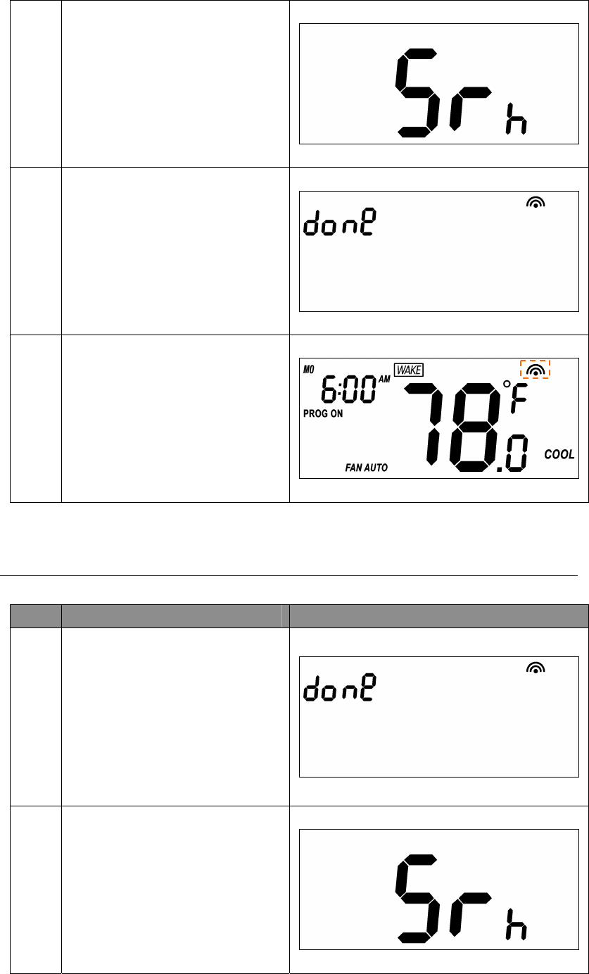
3
If the ZTS-100 is added into the
network, the signal of “done” will
be shown.
Inclusion is completed.
4
Press “Home" key once to go
back to the home page.
Delete (Exclusion) ZTS-100 from Gateway / Controller Z-Wave network
Step Procedure / Description LCD indication
1
Gateway / Controller device should
entry the Exclusion mode.
Press and hold “Home” key for 2
seconds to entry the Add
(Inclusion) / Delete (Exclusion)
Mode.
2
Press “Prog" key once, it will
search the network.
24
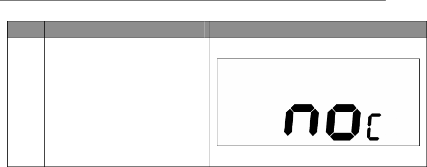
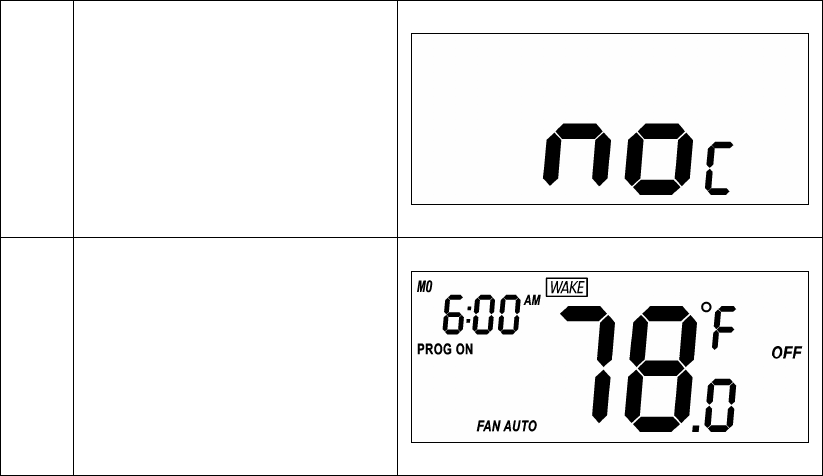
3
If the ZTS-100 is removed from the
network, it shows no connection.
Exclusion is completed.
4
Press “Home" key once to go
back to the home page.
Support Association Command Class
ZTS-100 support 2 association groups, each association group contains 5 nodes max. and up to 5
nodes can be assigned in these 2 association groups.
Association group_1:
z ZTS-100 will send out basic set command 0xFF automatically once Heat Pump operation has been
started in heating mode.
z ZTS-100 will send out basic set command 0x00 automatically once Heat Pump operation has been
stopped in heating mode.
Association group_2:
z ZTS-100 will send out basic set command 0xFF automatically once Compressor operation has been
started in cooling mode.
z ZTS-100 will send out basic set command 0x00 automatically once compressor operation has been
stopped in cooling mode.

25
Z-Wave Configuration Command
Parameter Number Definitions Parameter value range
1 (0x01) Swing 0x01 = 0.5 oC / 1 oF
0x02 = 1.0 oC / 2 oF (default)
0x03 = 1.5 oC / 3 oF
0x04 = 2.0 oC / 4 oF
2 (0x02) Differential 0x01 = 0.5 oC / 1 oF
0x02 = 1.0 oC / 2 oF (default)
0x03 = 1.5 oC / 3 oF
0x04 = 2.0 oC / 4 oF
3 (0x03) Set filter counter 0x01F4 to 0x0FA0 (default = 0x01F4,
resolution = 0x0064)
(500 to 4000 hours; resolution=100hrs )
4 (0x04) Report filter counter
(read only)
0x0000 to 0x270F
(0 to 9999 hours)
5 (0x05) Scale of temperature 0x00 = oC
0x01 = oF (default)
6 (0x06) Upper limit of set point (A) (A) available range:
Celsius (oC):
A = (B+2)min. ~ (37.0oC) max.
Fahrenheit (oF):
A = (B+4)min. ~ (99.0oF) max.
(default = 99.0oF)
7 (0x07) Lower limit of set point (B) (B) available range:
Celsius (oC): 5.0oC to 35.0oC
Fahrenheit (oF): 41.0oF to 95.0oF
(default = 41.0oF)
8 (0x08) Simple mode 0x00 = Disable (Normal mode)
0x01 = Enable (Simple mode), default
9 (0x09) Time format 0x00 = 24 hours
0x01 = 12 hours (am / pm), default
26
Filter Counter
Step Procedure / Description LCD indication
1
Press and hold “Fan” key for 2
seconds to check the filter counter.
The “usage hours” will be shown
on screen.
2
Press and hold “Prog” key for 2
seconds to reset the filter counter
after replace a new filter.
3
Press and hold “Mode” key to set
the alert time for the filter usage.
“Target” icon will be shown on
screen and flashing.
Press “UP” or “Down” to set the
alert time.
(Range from 500 to 4000 Hours
Step size is 100hrs)
Press “Prog” key to confirm the
setting and go back to filter
counter page.
Press “Home" key once to go
back to the Home page.
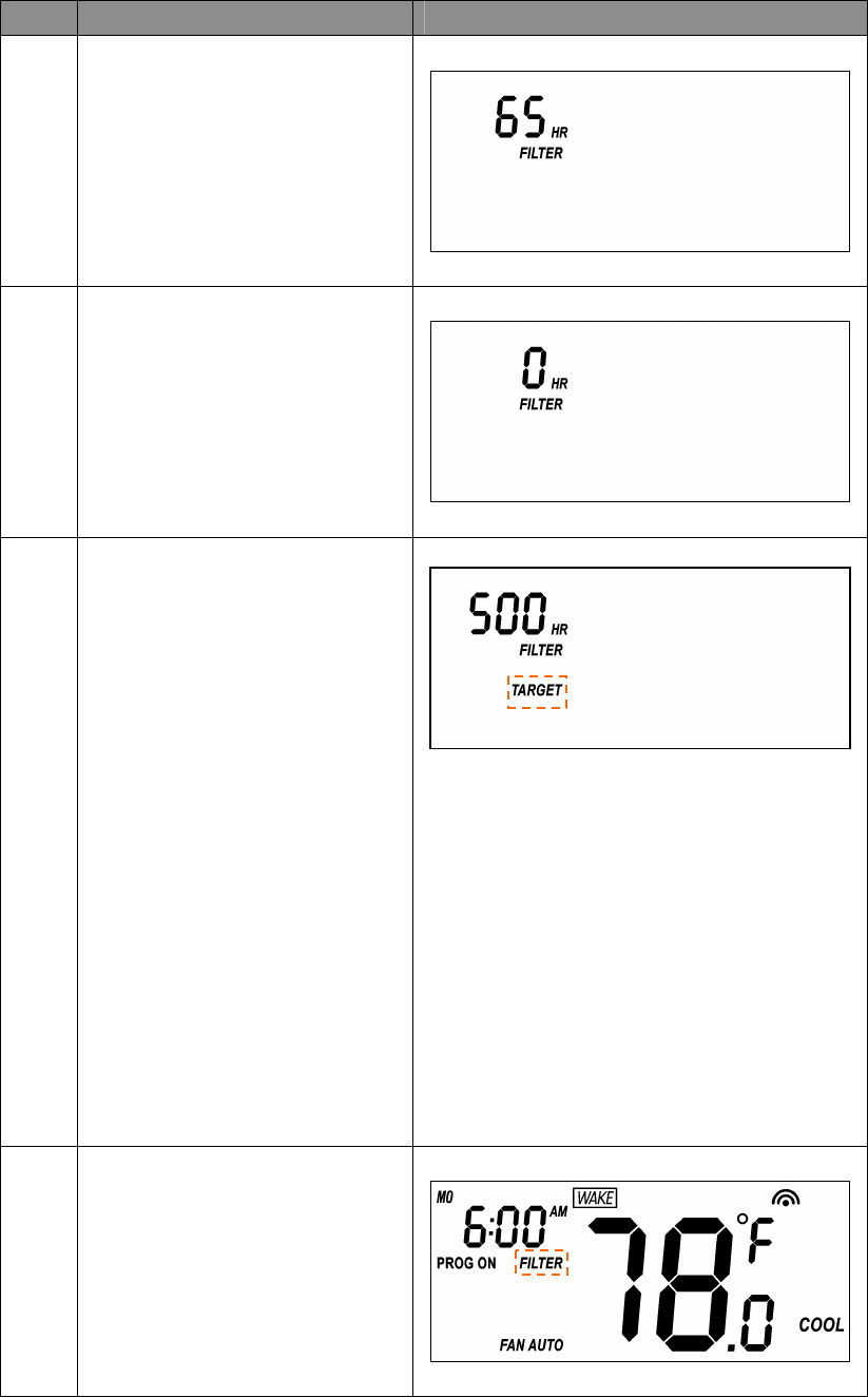
4
FILTER icon will be shown on the
screen at Home page when the
usage hours were reached to set
time.
27
Reset ZTS-100 to Factory Default Settings
Step Procedure / Description LCD indication
1
Press and hold “Fan ” +
“Mode" keys for 2 seconds to
entry the reset mode.
Press Up/Down key to toggle
Yes/No selection.
⇓
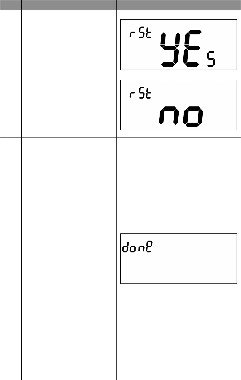
2
Press “Prog" key once to
confirm the action.
=> It will perform the reset if select
“Yes" or
=> It will back to home page if
select “No".
LCD display done after reset to
factory default settings.
(The following data will be reset to
default:
1. Clock : 12:00am
2. Day: Mon
3. Temperature scale: F
4. Swing : 2F
5. Diff: 2F
6. Default schedule
7. Operation mode: OFF
8. Default Heat override set point
9. Default Cool override set point
10. Filter counter cleared
11. Delete from network
28
Battery Low Indication
Step Procedure / Description LCD indication
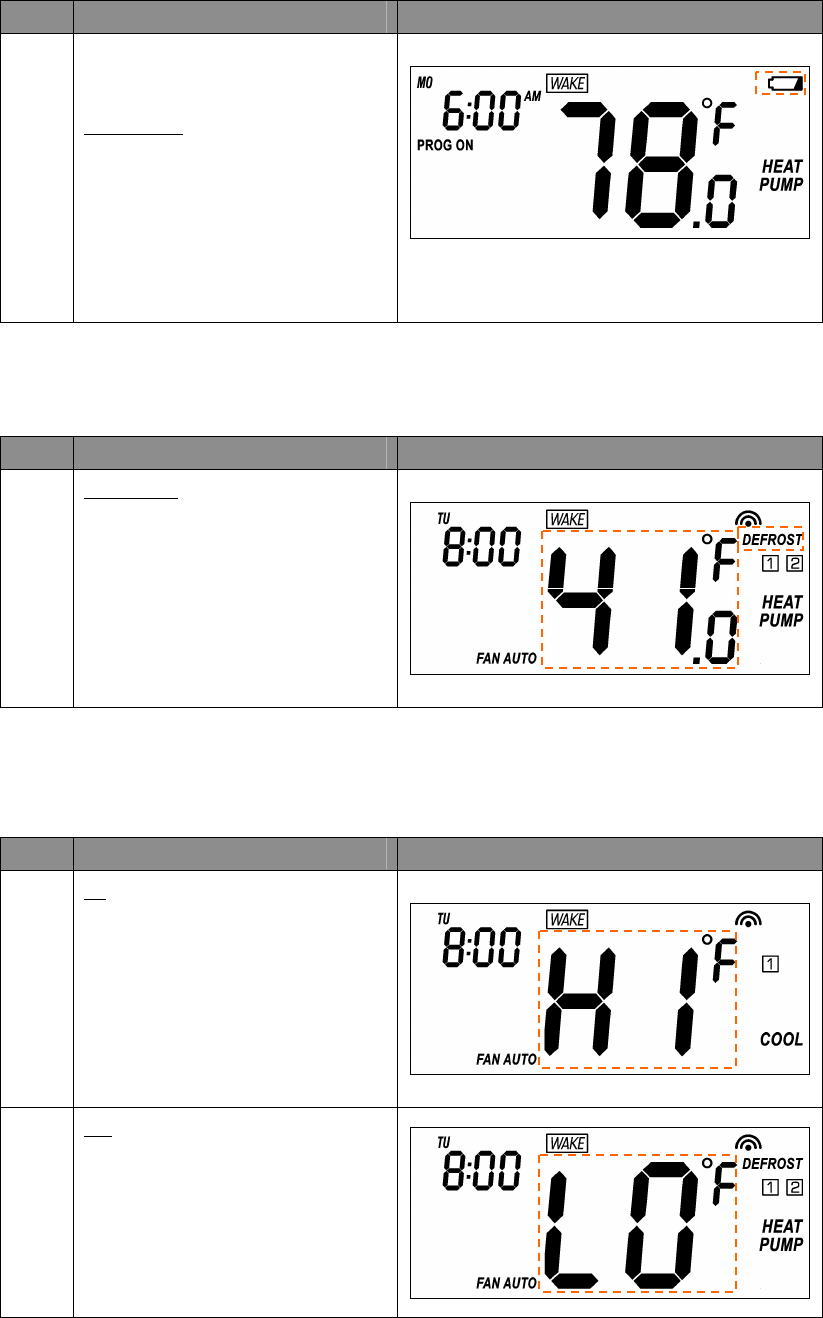
1
ZTS-100 thermostat will detect the
battery level every 30 minutes;
Battery low icon will be displayed
at Home page if the battery is
running out.
(User is required to change new
batteries.)
Defrost Indication
Step Procedure / Description LCD indication
1
DEFROST icon will be displayed
at Home page if temperature below
41°F/5°C
All heaters will be forced On,
except in cool mode.
Out of Temperature Range Indication
Step Procedure / Description LCD indication
1
HI icon will be displayed on LCD
if temperature excess the
measurement ranges 99°F/40°C.
All heaters will be forced Off.
Cooler will turn on if running cool
mode.
2
LO icon will be displayed on LCD
if temperature below the
measurement ranges 32°F/0°C.
All heaters will be forced On,
except in cool mode.
29
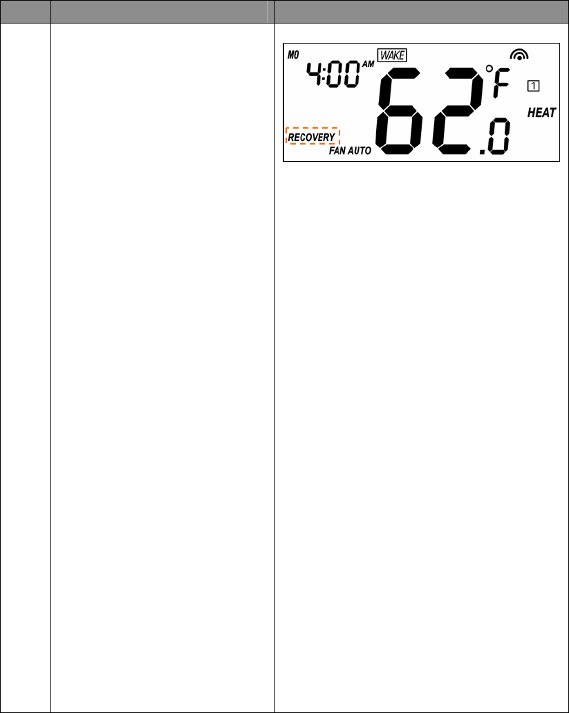
Advanced Recovery Indication
Step Procedure / Description LCD indication
1
The Advanced Recovery feature
allows heating and cooling systems
to gradually recover from an
energy-saving set point temperature
to a comfort set point temperature.
Advanced Recovery calculates the
time needed to adjust the
temperature to the next program
setting. When the thermostat is in
Advanced Recovery mode, the
display will show “RECOVERY”.
Advanced Recovery is an option
that allows the HVAC system to
attempt to recover from a setback
period and reach a desired comfort
temperature set point by the
beginning of your programmed
comfort period. This option allows
the choice whether to use
Advanced Recovery under Setting
Mode.
(Recovery works in heat, cool and
auto mode.
Maximum Advanced Recovery
time is one hour.)

30
Energy Saving Mode
Step Procedure / Description LCD indication
1
User can enable/disable energy
saving mode by using Z-Wave
BASIC set command only.
=> Enable energy saving mode
Basic set value = 0x00 (off mode)
(energy saving mode will be mapped
to off mode)
=> Disable energy saving mode
Basic set value = 0xFF (resume
mode)
(comfort mode will mapped to
resume mode)
-
31
Short Cycle Start Up Protection
To protect the compressor / Heat pump, those outputs forced off until 3minutes count down finished.
Those outputs can be activated according to the room temperature after 3 minutes.
System Output
Non Heat pump system Compressor
Heat pump system 1st stage heat and compressor
Frequently Asked Questions
Q Why won’t my ZTS-100 work with the Z-Wave devices I purchased from another country?
A Due to different countries regulations Z-Wave products from different regions are set to different
frequencies. Before purchasing new devices make sure you have checked to see that the device is
compatible in your region.
Q Do I need an electrician to install ZTS-100 in my house?
A It is recommended to install this product by a qualified technician.
Q How do I know which product is compatible to my ZTS-100?
A ZTS-100 should work with any Z-Wave controller or gateway that has control capability for
“Thermostat” devices. You can check either the specifications in the manual of your ZTS-100 or
also check online at www.remotec.com.hk for a full list of products that can be used with your
ZTS-100. All Z-Wave products also come with the Z-Wave logo.
Q Can I use 2 or more ZTS-100 in my house? What is the max. units if yes?
A Yes and it is very depends on the capability of gateway / controller. For example, gateway can
supports up to 8, 16 or 32 ZTS-100 in a network.
Q Where can I keep up to date with the latest Z-Wave products for my house?
A You can keep up to date by visiting the www.remotec.com.hk website where we will have
information and ideas for using Z-Wave technology.
Q What are the operation for Swing and Differential set point?
A Below are the detail explanations.
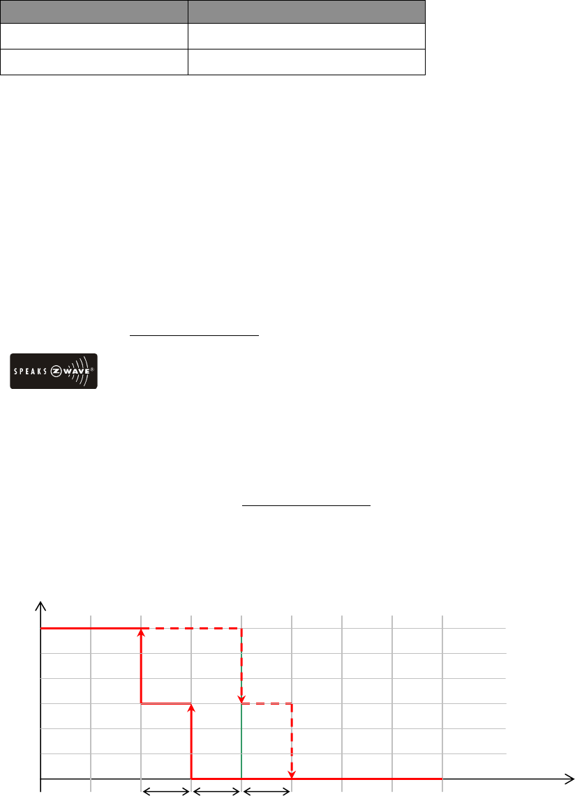
HEAT mode: thermostat controls the temperature according to the following diagram
Example for Heating: (Set point = 70 °F, Swing = 1 °F, Differential = 2 °F)
=> 1st stage heater turns on when room temp is 69 °F and off at 71 °F.
=> 2nd stage heater turns on when room temp is 67 °F and off at 70 °F.
Output Set point
Temperature
Swing
1s
t
Turn off
1s
t
Turn on
Off
Heat
2n
d
Turn on 2n
d
Turn off
Diff SD= switch differential
Swing
32
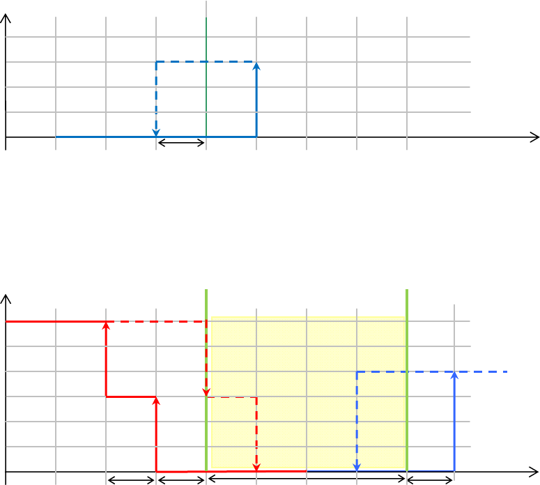
COOL Mode: thermostat controls the temperature according to the following diagram
Example for Cooling: (Set point = 80 °F, Swing = 1 °F)
=> Cooler turns on when room temp is 81 °F and off at 79 °F.
AUTO: thermostat controls the temperature according to the following diagram
There is a dead band 4°F/2°C between heat set point and cool set point.
Example 1: If user select heat set point is 70F, the minimum cool set point will be limited
at “heat set point + 4°F: 74°F
Pervious heat set point is 70°F and cool set point is 74°F
Example 2: If user changes heat set point to 72F, cool set point will be updated to 76°F
automatically to maintain the dead band.
Set point
Temperature
Turn off Turn on
Off
Cool
Swing
swing Dead band
Output
Heat Set point
Temperature
1s
t
Turn off
1s
t
Turn on
Off
Heat
2n
d
Turn on 2n
d
Turn off
Cool Set point
swing
Diff

33
Technical Specifications
Model no. BW8030US (ZTS-100US) / BW8031US (ZTS-110US)
BW8030AU (ZTS-100AU) / BW8031AU (ZTS-110AU)
BW8030EU (ZTS-100EU) / BW8031EU (ZTS-110EU)
RF frequency 908.4MHz (US) (ZTS-100US / ZTS-110US)
921.4MHz (AU) (ZTS-100AU / ZTS-110AU)
868.4MHz (EU) (ZTS-100EU / ZTS-110EU)
RF operating distance up to 100ft outdoor line of sight, in unobstructed environment
Z-Wave association group Support 2 association groups;
• Each association group contains 5 nodes max.
• Up to 5 nodes can be assigned in 2 association groups.
LCD TN type with white backlight
VA=66.5mmx28.5mm
Powered by Dry battery AA x 4pcs or
24 VAC +/- 20% 50/60Hz
Relay contact Voltage: 24 VAC 50/60 Hz
Current: 1A Max. (inductive)
Temperature measurable range 32 – 99 °F / 0 – 40 °C
Temperature display resolution 0.5°F / 0.1 °C
Temperature Setting range 41-99 °F / 5-37 °C
Temperature Operating: 32 – 122 °F / 0 – 50 °C
Storage: 23 – 140 °F / -5 – 60 °C
Dimension (L x H x T) 145mm x 100mm x 25mm
Weight 170g (Batteries excluded)
Z-Wave device type
Basic Device Class: Routing_Slave (Enhanced_Lib)
Generic Device Class: Thermostat
Specific Device Class: Thermostat general v2
Z-Wave Command Class Controlled Supported
COMMAND_CLASS_THERMOSTAT_FAN_MODE NO YES
COMMAND_CLASS_THERMOSTAT_FAN_STATE NO YES
COMMAND_CLASS_THERMOSTAT_MODE NO YES
COMMAND_CLASS_THERMOSTAT_SETPOINT NO YES
COMMAND_CLASS_THERMOSTAT_OPERATING_STATE NO YES
COMMAND_CLASS_THERMOSTAT_SETBACK NO YES
COMMAND_CLASS_SENSOR_MULTILEVEL NO YES
COMMAND_CLASS_CLOCK NO YES
COMMAND_CLASS_BATTERY NO YES
COMMAND_CLASS_BASIC YES YES
COMMAND_CLASS_VERSION NO YES
COMMAND_CLASS_MANUFACTURER_SPECIFIC NO YES
COMMAND_CLASS_ASSOCIATION NO YES
COMMAND_CLASS_CONFIGURATION NO YES
34
Checking Accessories
After opening the cover of the packing box, check that the following accessories are included.
• ZTS-100: Z-Thermostat
• Screw + Wall Anchor x 4pcs
• User Manual (download from our website)
FCC Notice
This device complies with Part 15 of the FCC rules. Operation is subject to the following two
conditions:
(1) this device may not cause harmful interference, and
(2) this device must accept any interference received, including interference that may cause
undesired operation.
NOTE: This equipment has been tested and found to comply with the limits for a Class B digital
device, pursuant to Part 15 of the FCC Rules. These limits are designed to provide reasonable
protection against harmful interference in a residential installation. This equipment generates, uses
and can radiate radio frequency energy and, if not installed and used in accordance with the
instructions, may cause harmful interference to radio communications. However, there is no
guarantee that interference will not occur in a particular installation. If this equipment does cause
harmful interference to radio or television reception, which can be determined by turning the
equipment off and on, the user is encouraged to try to correct the interference by one or more of the
following measures:
- Reorient or relocate the receiving antenna.
- Increase the separation between the equipment and receiver.
- Connect the equipment into an outlet on a circuit different from that to which the receiver is
connected.
- Consult the dealer or an experienced radio/TV technician for help.
Warnings
Changes or modifications not expressly approved by the party responsible for compliance could void
the user's authority to operate the equipment.
- RISK OF FIRE
- RISK OF ELECTRICAL SHOCK
- RISK OF BURNS
Do not dispose of electrical appliances as unsorted municipal waste, use separate collection facilities.
Contact your local government for information regarding the collection systems available.
Caution
- Risk of explosion if battery is replaced by an incorrect type.
- Dispose of used batteries according to the instructions.
www.remotec.com.hk
Printed in China F820-8030-0001