Remotec Technology BW8170 Z-Wave Smart Thermostat User Manual
Remotec Technology Limited Z-Wave Smart Thermostat Users Manual
UserManual.wiki
>
Remotec Technology
>
BW8170 User Manual
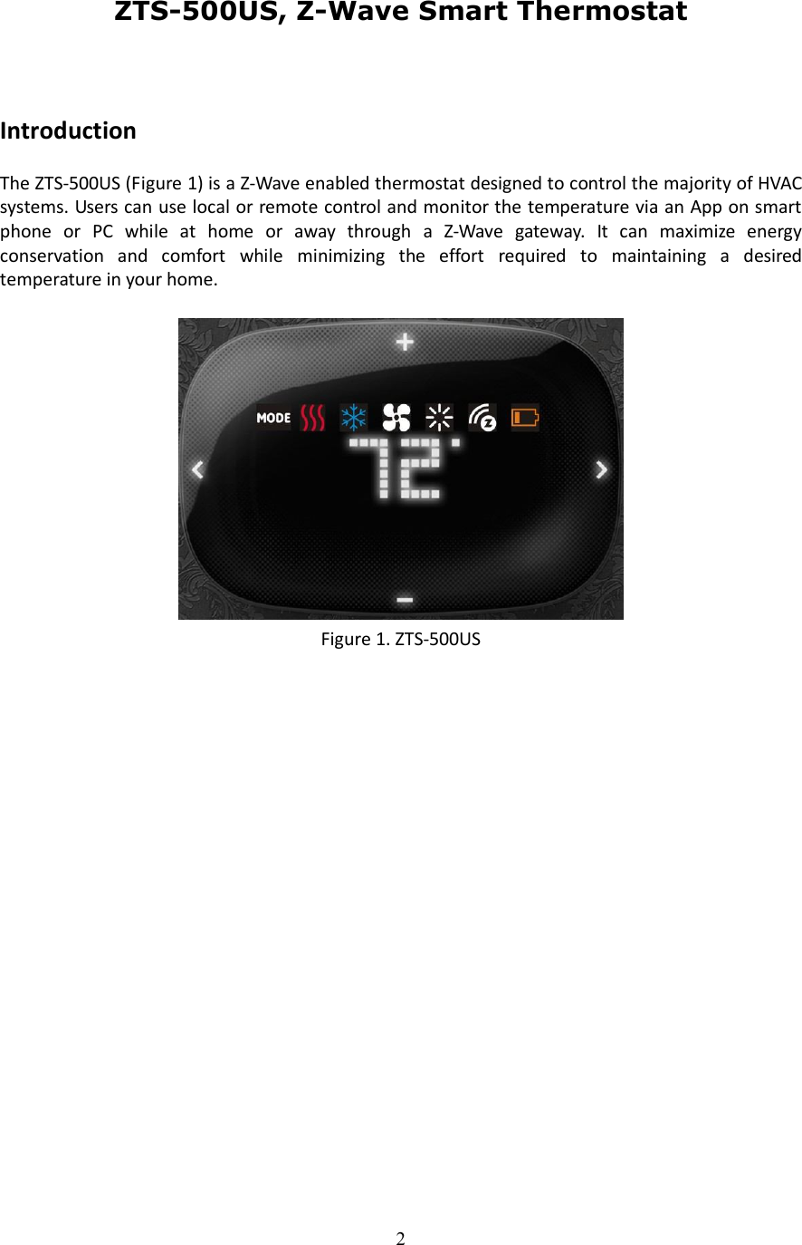
Users Manual
Navigation menu
Upload a User Manual
Namespaces
Wiki Guide
HTML
PDF
Info
Views
User Manual
Discussion / Help
Navigation
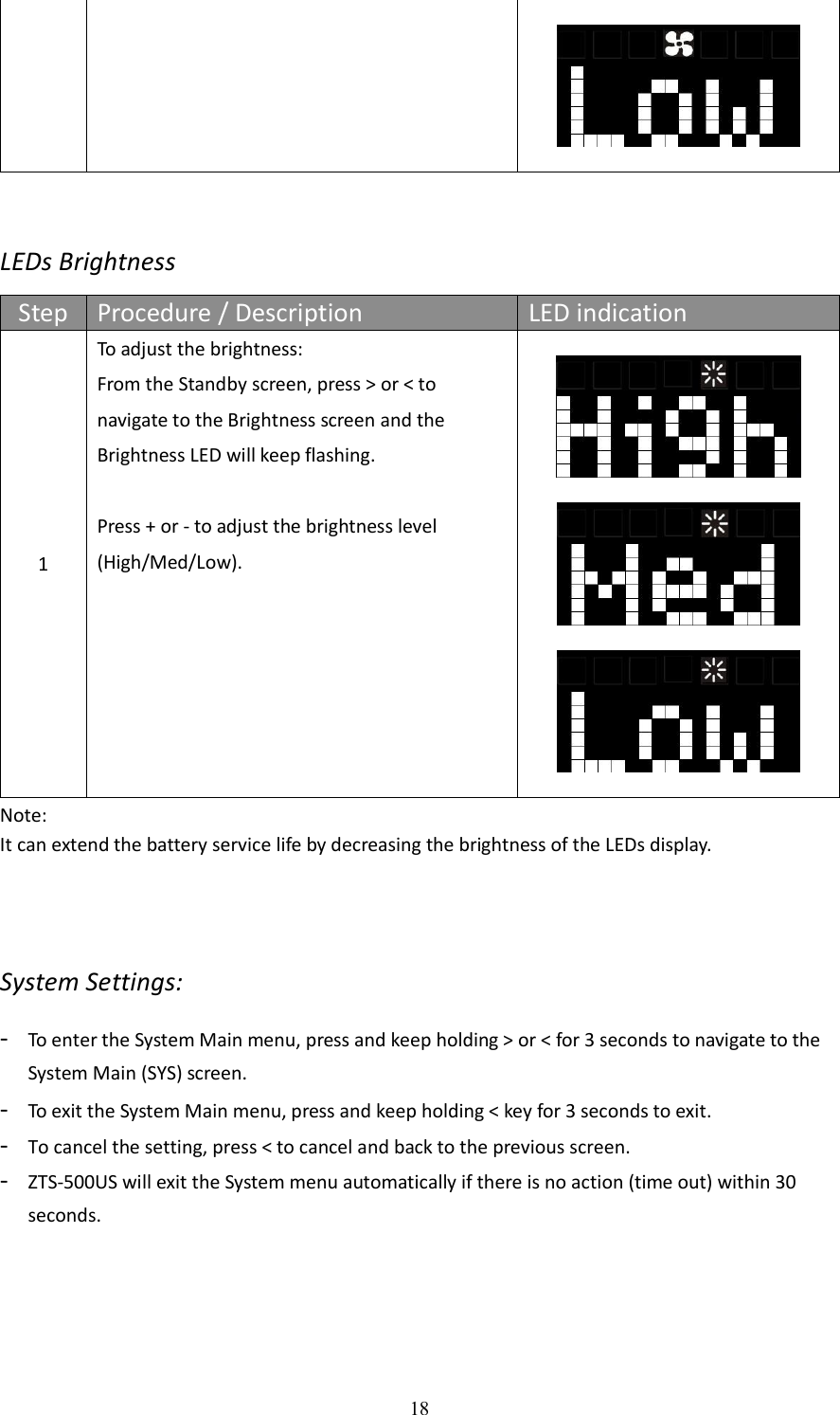
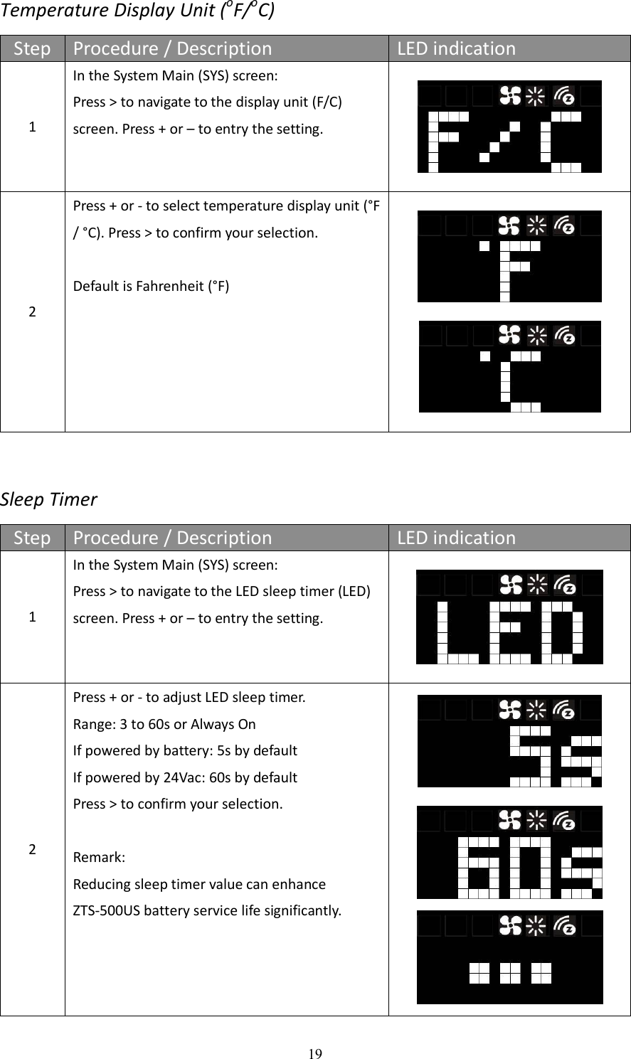
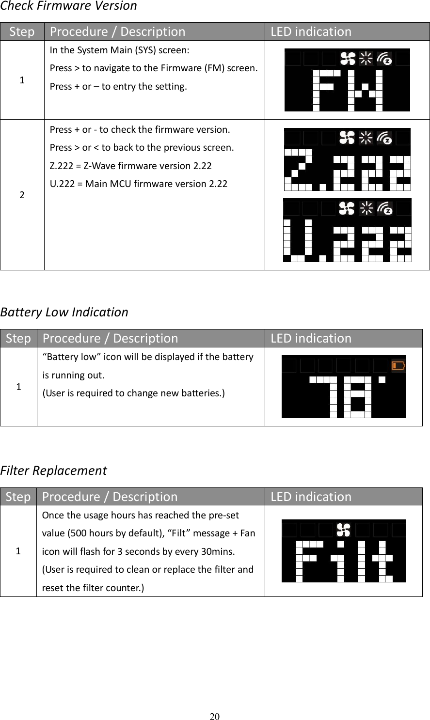
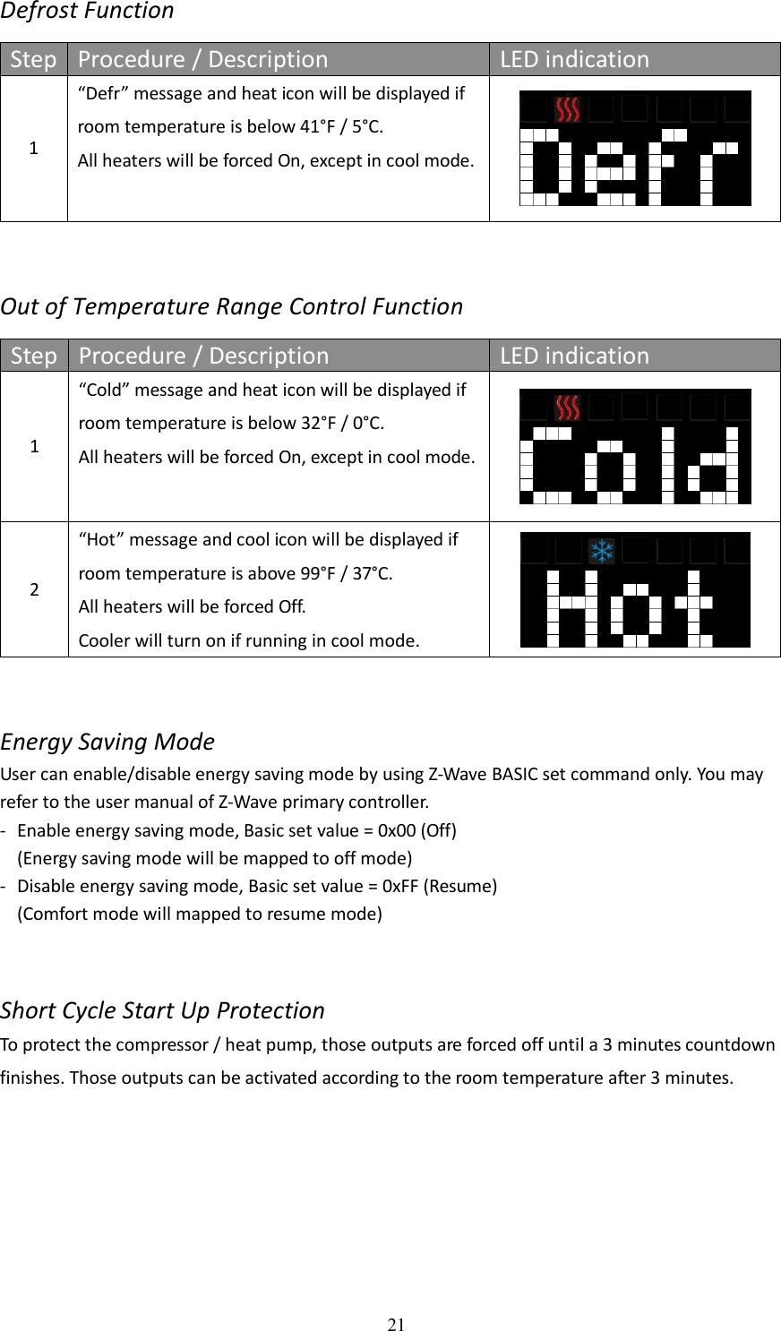
![27 f) Cool set point (report in precision of 0.5oC or 1oF) g) Current room temperature (report in precision of 0.5oC or 1oF) (It will trigger room temperature report if there is 2oF / 1oC [default] differ from last report. You can change this setting by set the configuration parameter) Notes: Total 5 devices (nodes) can be assigned in total 3 association groups. Below table lists out the devices (nodes) allocations in the 3 association groups. No. of Node ID in Association Group_1 No. of Node ID in Association Group_2 No. of Node ID in Association Group_3 1 (AUTO report) 0,1 or 2 nodes 0,1 or 2 nodes Important: Please do not associate heater and compressor devices in same association group because heater and compressor device can’t turn on in simultaneously! Example: Association groups setting F-BW8170 (ZTS-500US) F-BW8041 (ZFM-80) (Node ID-B) F-BW8041 (ZFM-80) (Node ID-C) Z-Wave Gateway (Node ID-A) Association group_2 for Heater Association group_3 for Compressor Association group_1 for Auto report to gateway F-BW8041 (ZFM-80) (Node ID-D) F-BW8041 (ZFM-80) (Node ID-E)](https://usermanual.wiki/Remotec-Technology/BW8170/User-Guide-2953685-Page-27.png)