Remotec Technology BW8170 Z-Wave Smart Thermostat User Manual
Remotec Technology Limited Z-Wave Smart Thermostat Users Manual
Users Manual
1
ZTS-500US
Z-Wave Smart Thermostat
2
ZTS-500US, Z-Wave Smart Thermostat
Introduction
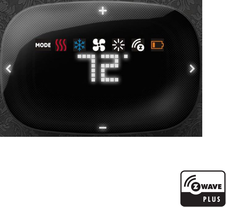
The ZTS-500US (Figure 1) is a Z-Wave enabled thermostat designed to control the majority of HVAC
systems. Users can use local or remote control and monitor the temperature via an App on smart
phone or PC while at home or away through a Z-Wave gateway. It can maximize energy
conservation and comfort while minimizing the effort required to maintaining a desired
temperature in your home.
Figure 1. ZTS-500US
3
Features List
HVAC System Compatible:
Standard (Gas/Electric) or Heat Pump HVAC systems
Multi-stage System Compatible:
Standard HVAC Systems: 2 stages heating, 2 stages cooling, 2 stages fan
Heat Pump Systems: 2 stages heating, 2 stages cooling, 2 stages fan
Heat Pump change over valve:
Selectable change over with heat or cool (B or O output)
Fan system:
Selectable for gas or electric heat systems
Temperature Display, Indication and Control:
Temperature unit in °F or °C
Temperature Measurable Range: 32 - 99 °F / 0 - 37 °C
Temperature Setting Range: 41 - 99 °F / 5 - 37 °C
Adjustable Temperature Control Swing, Differential and Dead band
a) Swing: 1°F, 2°F, 3°F or 4°F ( 0.5°C, 1.0°C, 1.5°C or 2°C)
b) Differential: 1°F, 2°F, 3°F or 4°F ( 0.5°C, 1.0°C, 1.5°C or 2°C)
c) Dead band: 3°F, 4°F, 5°F or 6°F ( 1.5°C, 2.0°C, 2.5°C or 3°C)
Temperature sensor calibration
Filter replacement reminder after 500 hours usage (adjustable 500-4000hrs)
Defrost function and Out of temperature range control function
Energy saving mode
Short cycle start up protection
White LEDs display:
Resolution: 18 x 6 dots
View area: 64mm x 28mm
Status icons: 7
Wide viewing angle and high contrast ratio with 3 levels brightness control
Z-Wave:
Support “Frequently Listening Routing Slaves” (FLiRS) mode and “Always Listening” mode
Support Network Wide Inclusion (NWI) and Explore Frames
Support Security and Non- Security command
Support battery low and level report
Support Association Groups
a) Association Group-1 is a default status (AUTO) report channel in Z-Wave+ lifeline.
b) Association Group-2 is used for Heat Pump control
c) Association Group-3 is used for Compressor control
Advanced features through Z-Wave configuration parameters
Z-Wave Plus compliant
Wiring Requirements:
Uses standard thermostat connections (C, RC,RH, W1, W2, Y1,Y2, G1, G2, O, B) – AWG #18
wires
Power Requirements:
Support AA x 2 or AA x 4 alkaline batteries (No C-wire required) or standard HVAC 24Vac

4
Physical Installation and Wiring
C
aution
s
!
We highly recommend that this installation procedure is performed by a trained HVAC
technician.
Read the enclosed instructions carefully before installing your new ZTS-500US. Pay close
attention to all warnings and notes and carefully follow the installation steps in the order
they are presented to save time and minimize the risk of damaging the thermostat or the
system it controls.
Before disconnecting wires from the existing thermostat, label the wires with the terminal
markings from the old thermostat and record them. Take a picture of the old wiring as it will
be very helpful with troubleshooting in case you need to reinstall the old unit.
Turn off electronic devices (e.g. heater, cooler) which will be connected and the electric
source before installation and maintenance.
Do not use metal conduits or cables provided with a metal sheath.
Adding fuses or protective device in the line circuit is recommended.
Battery safety!
Use new batteries of the recommended type and size only.
Never mix used and new batteries together.
To avoid chemical leaks, remove batteries from the ZTS-500US if you do not intend to use the
unit for an extended period of time.
Dispose of used batteries properly; do not burn or bury them.
Read following scenarios carefully before you start as it matters to the battery life under Z-Wave
operation:
Installation Location
This thermostat is restricted to indoor use only. It should be mounted on an inner wall about 5ft
(1.5m) above the floor at a position where it is readily affected by changes of the general room
temperature with freely circulating air. Avoid mounting above or near hot surfaces or equipment
(e.g. TV, heater, refrigerator). Avoid mounting where it will be exposed to direct sunshine, drafts,
or in a laundry room or other enclosed space. Do not expose this unit to dripping or splashing
liquids.
Physically Installing the Thermostat
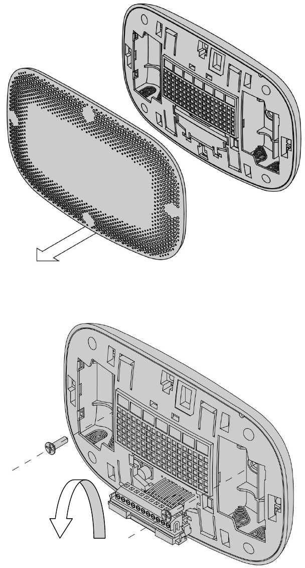
1. Open the ZTS-500US by pulling the two sections apart (Figure 2). Use the fingertips of one hand
to grip the tab on the front housing.
2. Insert the two included wall anchors into the wall, aligned with two of the mounting holes in
the back housing of the thermostat.
3. Open the terminal block of the ZTS-500US then insert all necessary wires through the back
housing (Figure 3).
4. Fasten the back housing to the wall using the two included mounting screws. Insert the screws
through the mounting holes in the housing and into the wall anchors (Figure 3).
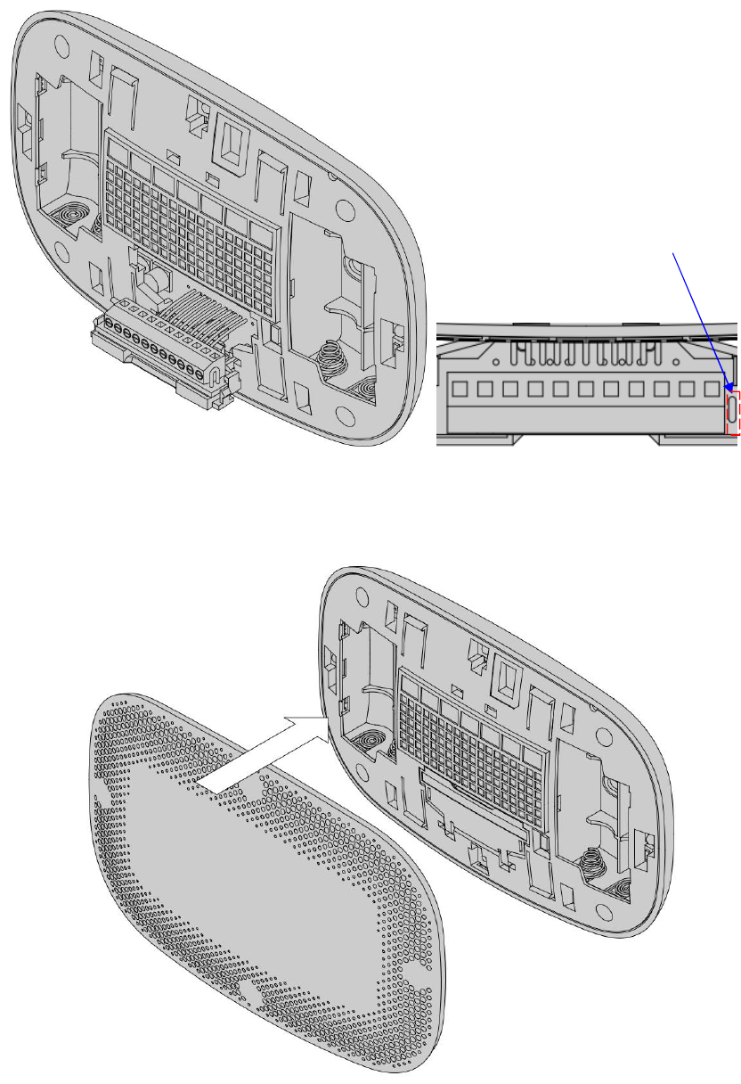
5. Wire the proper cables to the terminal block according to the circuit diagram as described in
figure 4 and "Thermostat Terminal Wiring". Afterward, push all cables back into the wall then
close the terminal block of the ZTS-500US.
6. The ZTS-500US can be powered by either two AA Alkaline batteries or four AA Alkaline
batteries.
Match the polarity of the batteries with the +/- marks inside the battery compartment.
7. Align the front housing of the thermostat with the back housing and push until the housing
5
sections are locked together (Figure 5).
Figure 2. Open ZTS-500US front housing
Figure 3. Open the terminal and mount into the wall
6
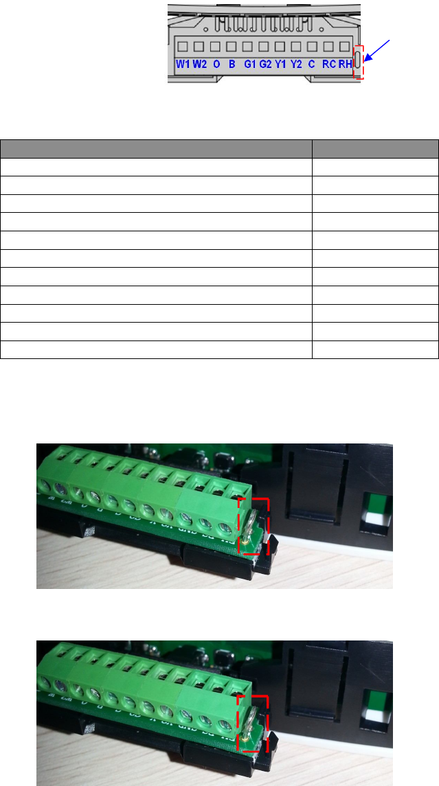
Figure 4. Terminal wiring
Figure 5. Install the front housing
W1 W2 O B G1 G2 Y1
Y2
C
RC RH
RC/RH jumper
7
Thermostat Terminal Wiring
Figure 6. Terminal block and pin assignment
Terminals
Symbol
1
st
s
tage
H
eater
W1
or W
2
nd
s
tage
H
eater
W2
Cool c
hangeover
(heat pump)
O
Heat c
hangeover
(heat pump)
B
1
st
stage
Fan
G
1 or G
2
nd
stage
Fan
G2
1
st
stage
Compressor
Y
1 or Y
2
nd
stage
Compressor
Y
2
24Vac Common
C
24V
ac
Power for C
ooling
R
C
24V
ac
Power for H
eat
ing
R
H
RC/RH jumper:
Most HVAC systems build-in a common heating and cooling transformer. The ZTS-500US
has a built-in RH/RC jumper wire to short RH and RC inputs for this configuration.
If the HVAC system contains separated heating and cooling transformers, please cut out
the RH/RC jumper and then connect the RC and RH inputs individually.
Thermostat wiring:
For Non-Heat Pump HVAC systems, please refer to figure 7, 8, and 9.
For Heat Pump HVAC systems, please refer to figure 10, 11, and 12.
RC/RH jumper
RC/RH jumper
Cut out RC/RH jumper!
8
Non-Heat Pump (standard) HVAC System
Important:
If there is no C-wire in the HVAC system, the ZTS-500US must be powered by batteries and it will
be operated in FLiRS mode after inclusion into a Z-Wave network.
Multi-stage: 2 Heat / 2 Cool
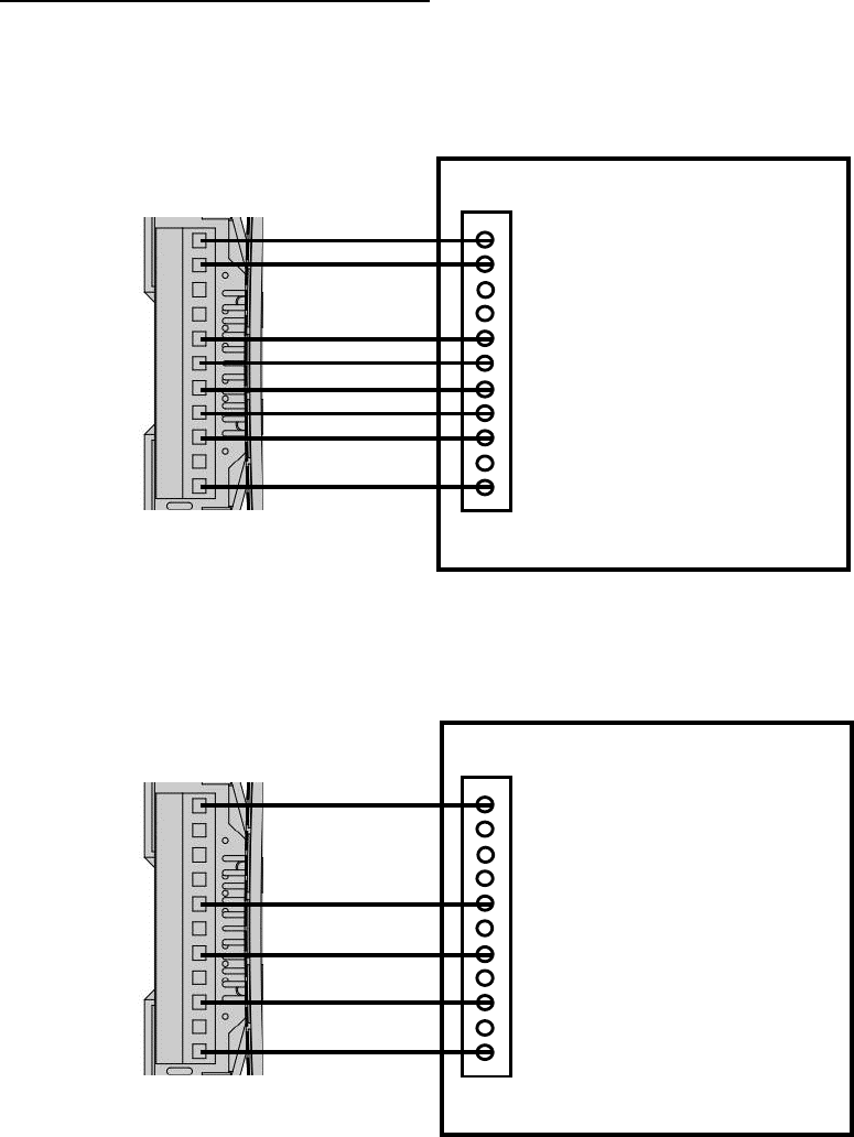
Figure 7. Non-heat pump (Standard Gas or Electric) HVAC system wiring
Single-stage: 1 Heat / 1 Cool
Figure 8. Non-heat pump (Standard Gas or Electric) HVAC system wiring
W1
W2
O
B
G1
G2
Y1
Y2
C
RC
RH
Black (with C-Wire)
Red
Yellow
Green
W1 - 1st stage Heater
W2 - 2nd stage Heater
G1 - 1st stage Fan
G2- 2nd stage Fan
Y1 - 1st stage Compressor (Cool)
Y2 - 2nd stage Compressor (Cool)
C - 24Vac Common
R - 24Vac Power
Non
-
Heat Pump (standard)
HVAC System
Vary
White
ZTS
-
500U
RC and RH are
internal short!
Vary
Vary
W1
W2
O
B
G1
G2
Y1
Y2
C
RC
RH
Black (with C-Wire)
Red
Yellow
Green
W - Heater
G - Fan
Y - Compressor (Cool)
C - 24Vac Common
R - 24Vac Power
Non
-
Heat Pump (standard)
HVAC System
White
ZTS
-
500U
RC and RH are
internal short!
Typical wire colour
Typical wire colour
9
2-wires system with 1 heat only
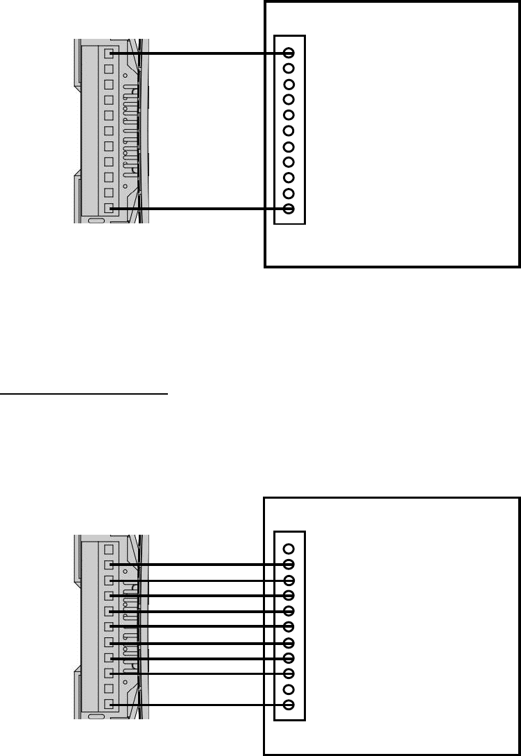
Figure 9. Non-heat pump (Standard Gas or Electric) 2-wires HVAC system wiring
Heat Pump HVAC System
Important:
If there is no C-wire in the HVAC system, the ZTS-500US must be powered by batteries and it
will be operated in FLiRS mode after inclusion into a Z-Wave network.
Do not split RC/RH for Heat Pump systems! Multi-stage: 2 Heat / 2 Cool
Figure 10. Heat pump HVAC system wiring
W1
W2
O
B
G1
G2
Y1
Y2
C
RC
RH
Black (with C-Wire)
Red
Yellow
W2 - 2nd stage Heater
O - Cool changeover (heat pump)
B - Heat changeover (heat pump)
G1 - 1st stage Fan
G2 - 2nd stage Fan
Y1 - 1st stage Compressor (Heat/Cool)
Y2 - 2nd stage Compressor (Cool)
C - 24Vac Common
R - 24Vac Power
Heat Pump HVAC System
Blue
Orange
ZTS
-
500U
Green
RC and RH are
internal short!
Vary
Vary
W1
W2
O
B
G1
G2
Y1
Y2
C
RC
RH
W - Heater
R - 24Vac Power
White
ZTS
-
500US
(Powered by batteries)
Red
RC and RH are
internal short!
Non
-
Heat Pump (standard)
HVAC System
Typical wire colour
Typical wire colour
No C-wire
Vary
10
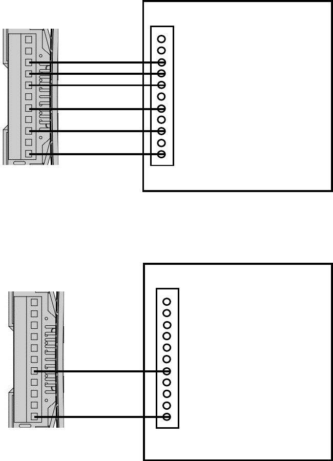
Do not split RC/RH for Heat Pump systems! Single-stage: 1 Heat / 1 Cool
Figure 11. Heat pump HVAC system wiring
2-wires system with 1 heat only
Do not split RC/RH for Heat Pump systems!
For heat pump output, there is a 3 minutes off time for heat pump protection!
Figure 12. Heat pump 2-wires HVAC system wiring
Yellow
W1
W2
O
B
G1
G2
Y1
Y2
C
RC
RH
Black (with C-Wire)
Red
Yellow
O - Cool changeover (heat pump)
B - Heat changeover (heat pump)
G - Fan
Y - Compressor (Heat/Cool)
C - 24Vac Common
R - 24Vac Power
Heat Pump HVAC System
Blue
Orange
ZTS
-
500U
Green
RC and RH are
internal short!
W1
W2
O
B
G1
G2
Y1
Y2
C
RC
RH
Y - Compressor (Heat)
R - 24Vac Power
ZTS
-
500US
(Powered by batteries)
Red
RC and RH are
internal short!
Heat Pump System
Typical wire colour
Typical wire colour
No C-wire
11
Setup and Operations
Product Overview
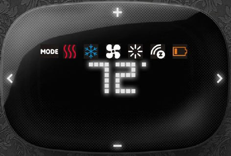
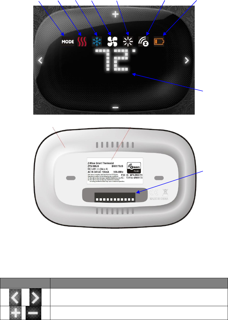
Figure 13. ZTS-500US
Description of Function Keys
Symbol Key Description
Navigation keys or confirmation keys
Scroll keys
Mode Heat Cool Fan Brightness Z-Wave Disconnect Battery Low
Current Temperature
Terminals
12
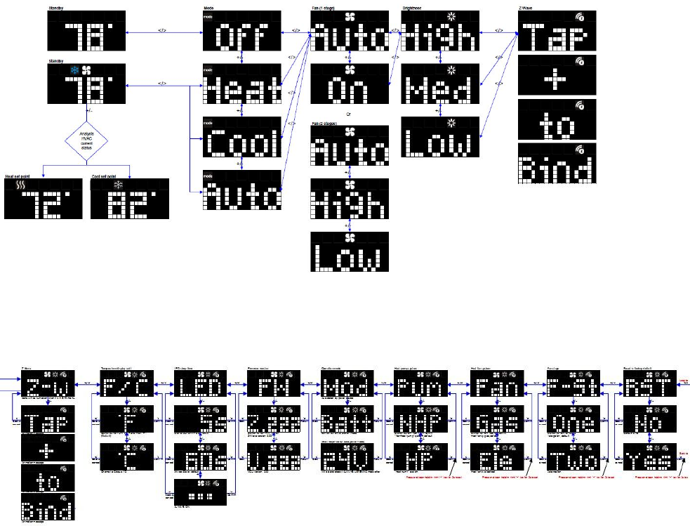
User Interface Layout
Operation menu:
System setup menu:
13
Initial HVAC System Setting
The ZTS-500US supports various different HVAC system types:
- Pump systems: Non-Heat Pump or Heat Pump
- Heat Fan systems: Gas-Powered or Electric-Powered
- Fan stage systems: One or two stages fan
To prevent abnormal operation, it is important that the ZTS-500US is set to the correct HVAC
system type prior to use and Z-Wave inclusion. To set the HVAC system type:
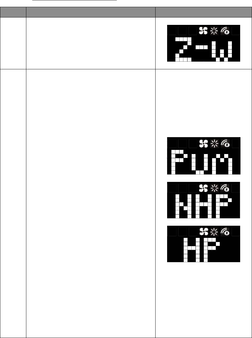
Step Procedure / Description LED indication
1
From the Standby screen, press and keep
holding > or < for 3 seconds to navigate to the
System Main (SYS) screen.
2
For Pump Systems:
Press > to navigate to the pump system (Pum)
screen. Press + or – to entry the setting.
Press + or - to select your pump system type,
either a non-heat pump system (NHP) or a heat
pump system (HP).
Press and keep holding > for 2 seconds to
confirm your selection.
Press < to cancel the setting and back to the
previous screen.
Non-heat pump: (pre-selected system)
- When there is a heating request, thermostat
will turn on W1.
- When there is a cooling request, thermostat
will turn on Y1.
Heat pump:
- When there is a heating request, thermostat
will turn on Y1 and B.
- When there is a cooling request, thermostat
will turn on Y1 and O.
14
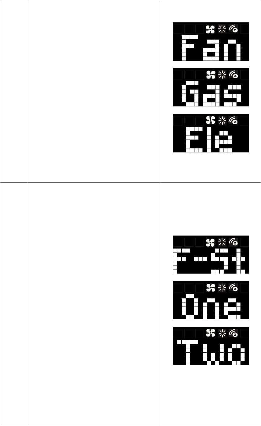
3
For Fan Systems:
Press > to navigate to the fan system (Fan)
screen. Press + or – to entry the setting.
Press + or - to select your fan system type, either
gas-powered (Gas) or electric-powered (Ele).
Press and keep holding > for 2 seconds to
confirm your selection.
Press < to cancel the setting and back to the
previous screen.
Gas-powered : (pre-selected system)
- Fan will maintain off state.
Electric-powered:
- Fan will be turned on when there is heating.
4
For Fan Stages:
Press > to navigate to the fan stage (F-St) screen.
Press + or – to entry the setting.
Press + or - to select your fan stage, either
one stage (One) or two stages (Two) fan.
Press and keep holding > for 2 seconds to
confirm your selection.
Press < to cancel the setting and back to the
previous screen.
One stage : (pre-selected system)
- Fan speed: Auto/On
Two stages:
- Fan speed: Auto/High/Low
Remark:
- To exit the System Main menu, press and keep
holding < key for 3 seconds.
- After inclusion procedure, fan stages cannot be
changed. You must perform exclusion procedure
first if fan stages need to be changed.
15
Note:
If the user performs a Reset to Factory Default Settings or Z-Wave Exclusion operation, the
ZTS-500US will retain the last selected HVAC system type.
Thermostat Mode and Set point
For normal setup and operations, ZTS-500US will take the action after key released and it will go
back to standby menu after 3 seconds.
Step Procedure / Description LED indication
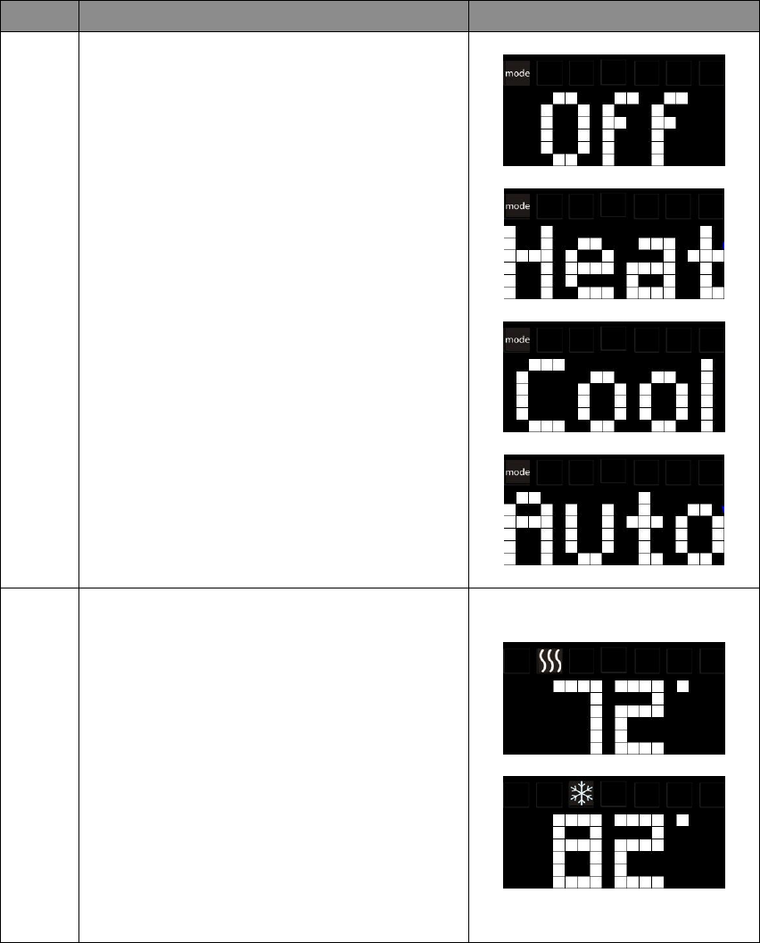
1
From the Standby screen, press > to navigate to
the Mode screen and the Mode LED will keep
flashing.
Press + or - to scroll to your HVAC mode
(Off/Heat/Cool/Auto).
2
From the Standby screen, press + or - to set your
desired temperature set point.
Remark:
- Heat or Cool icons with white colour will be
turned on when adjusting the heat or cool set
point.
- Heat icon with red colour will be turned on
once heater is active.
- Cool icon with blue colour will be turned on
once compressor is active.
16
Explanations of Set point, Swing, Differential and Dead band
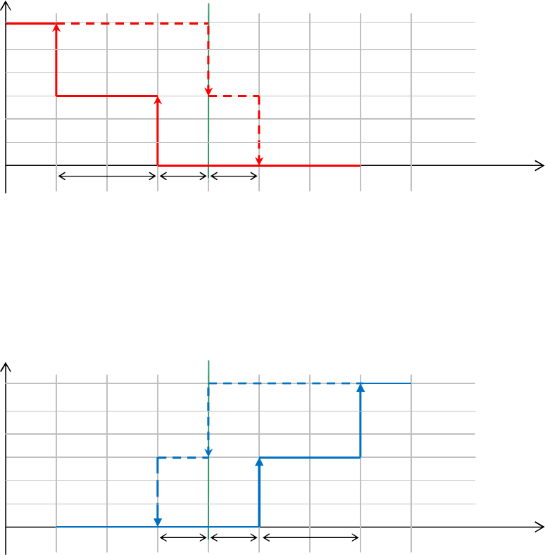
HEAT mode: Thermostat controls the temperature according to the following diagram
Example: If Heat Set point = 70°F, Swing = 1°F, Differential = 2°F, then
=> 1st stage heater turns on when room temp is 69°F and off at 71°F.
=> 2nd stage heater turns on when room temp is 67°F and off at 70°F.
COOL mode: Thermostat controls the temperature according to the following diagram
Example: If Cool Set point = 80°F, Swing = 1°F, Differential = 2°F, then
=> 1st stage cooler turns on when room temp is 81°F and off at 79°F.
=> 2nd stage cooler turns on when room temp is 83°F and off at 80°F.
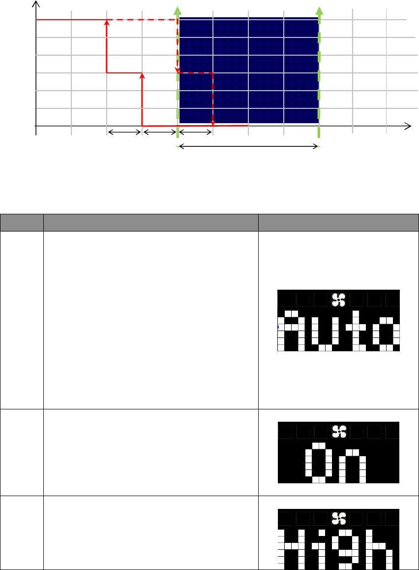
AUTO mode: Thermostat controls the temperature according to the following diagram.
Press + / - buttons to adjust the appropriate set point. It will adjust the set point that is
closer to the current room temperature.
If the current temperature is close to heat set point, then it will change the heat set point value.
If the current temperature is close to cool set point, then it will change the cool set point value.
If the difference between the two is equal, then it will change the heat set point value by default.
There is a dead band 4°F/2°C (by default) between heat set point and cool set point. If user select
heat set point is 73°F, then the minimum of cool set point will be limited to 77°F.
Output Set point
Temperature
Swing
1
st
stage
Turn off
1
st
stage
Turn on
Off
Heat
2
nd
stage
Turn on
2
nd
stage
Turn off = Set point
Diff Swing
Output Set point
Temperature
Swing
1
st
stage
Turn on
Off
Cool
Diff
Swing
2
nd
stage
Turn on
2
nd
stage
Turn off = Set point
1
st
stage
Turn off
67
o
F 68
o
F 69
o
F 70
o
F 71
o
F 72
o
F 73
o
F 74
o
F
77
o
F 78
o
F 79
o
F 80
o
F 81
o
F 82
o
F 83
o
F 84
o
F
17
Example: If Room temperature = 75°F, Dead band = 4°F, Swing = 1°F, Differential = 1°F
Heat Set point = 73°F, Cool Set point = 77°F
Then it will change the heat set point by +/- buttons.
If keep 73°F in heat set point, then the minimum of cool set point will be limited to 77°F,
=> 1st stage heater turns on when room temp is 72°F and off at 74°F.
=> 2nd stage heater turns on when room temp is 71°F and off at 73°F.
Fan Mode
Step Procedure / Description LED indication
1
To adjust the fan mode:
From the Standby screen, press > or < to
navigate to the Fan Mode screen and the Fan
LED will keep flashing.
When set to Auto:
- Electric-powered: Fan will run during heating
and cooling operation.
- Gas-powered: Fan will ONLY run during cooling
operation.
2
For one stage fan:
Press + or - to change the fan speed (Auto/On).
When set to On, the fan will stay ON.
3
For two stages fan:
Press + or - to change the fan speed
(Auto/High/Low).
When set to High/Low, the fan will stay ON.
Dead band
Output
Temperature
1
st
stage
Turn off
in Heat
1
st
stage
Turn on
in Heat
Off
Heat Set point
2
nd
stage
Turn on in Heat
2
nd
stage
Turn off in Heat
Swing
Diff
Cool Set point
Swing
70
o
F 71
o
F 72
o
F 73
o
F 74
o
F 75
o
F 76
o
F 77
o
F 78
o
F 79
o
F
18
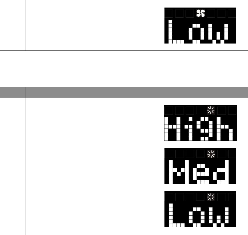
LEDs Brightness
Step Procedure / Description LED indication
1
To adjust the brightness:
From the Standby screen, press > or < to
navigate to the Brightness screen and the
Brightness LED will keep flashing.
Press + or - to adjust the brightness level
(High/Med/Low).
Note:
It can extend the battery service life by decreasing the brightness of the LEDs display.
System Settings:
- To enter the System Main menu, press and keep holding > or < for 3 seconds to navigate to the
System Main (SYS) screen.
- To exit the System Main menu, press and keep holding < key for 3 seconds to exit.
- To cancel the setting, press < to cancel and back to the previous screen.
- ZTS-500US will exit the System menu automatically if there is no action (time out) within 30
seconds.
19
Temperature Display Unit (oF/oC)
Step Procedure / Description LED indication
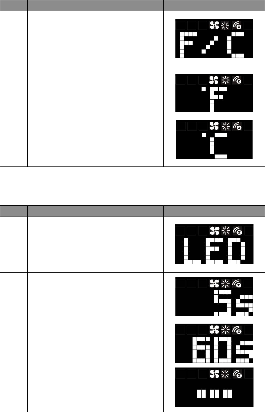
1
In the System Main (SYS) screen:
Press > to navigate to the display unit (F/C)
screen. Press + or – to entry the setting.
2
Press + or - to select temperature display unit (°F
/ °C). Press > to confirm your selection.
Default is Fahrenheit (°F)
Sleep Timer
Step Procedure / Description LED indication
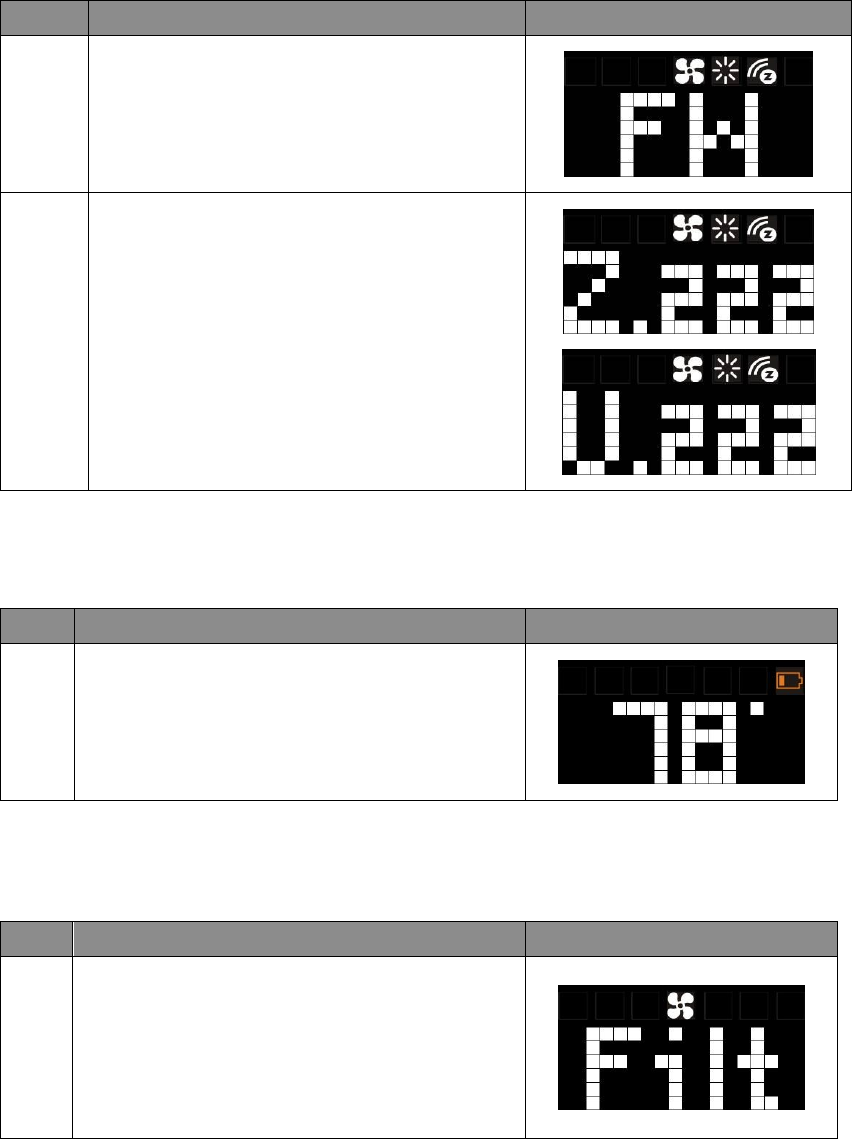
1
In the System Main (SYS) screen:
Press > to navigate to the LED sleep timer (LED)
screen. Press + or – to entry the setting.
2
Press + or - to adjust LED sleep timer.
Range: 3 to 60s or Always On
If powered by battery: 5s by default
If powered by 24Vac: 60s by default
Press > to confirm your selection.
Remark:
Reducing sleep timer value can enhance
ZTS-500US battery service life significantly.
20
Check Firmware Version
Step Procedure / Description LED indication
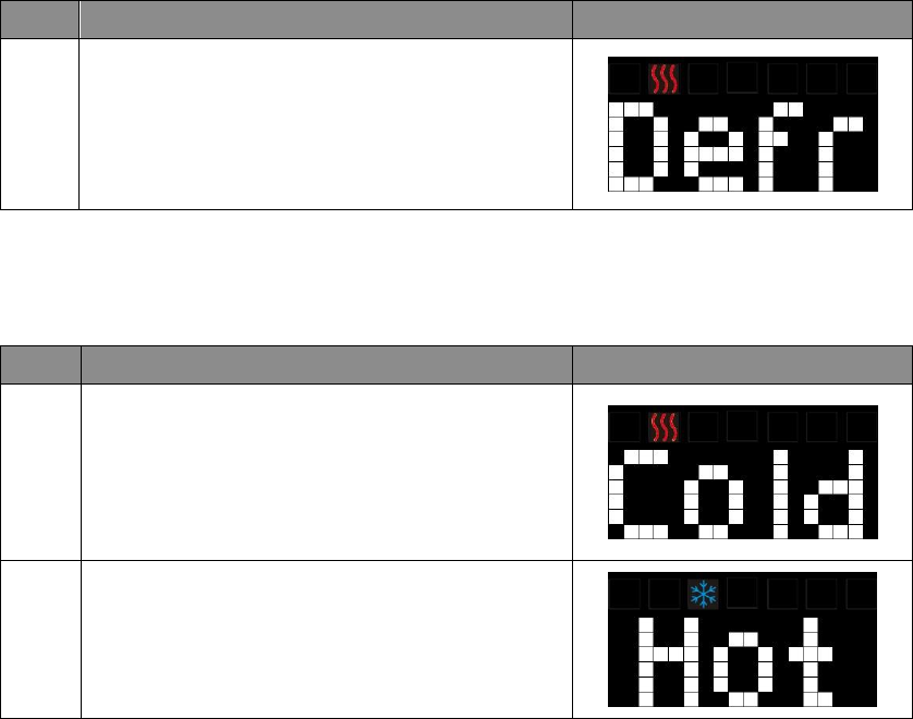
1
In the System Main (SYS) screen:
Press > to navigate to the Firmware (FM) screen.
Press + or – to entry the setting.
2
Press + or - to check the firmware version.
Press > or < to back to the previous screen.
Z.222 = Z-Wave firmware version 2.22
U.222 = Main MCU firmware version 2.22
Battery Low Indication
Step
Procedure / Description LED indication
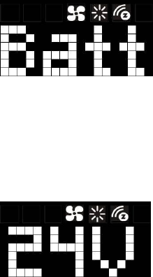
1
“Battery low” icon will be displayed if the battery
is running out.
(User is required to change new batteries.)
Filter Replacement
Step
Procedure / Description LED indication
1
Once the usage hours has reached the pre-set
value (500 hours by default), “Filt” message + Fan
icon will flash for 3 seconds by every 30mins.
(User is required to clean or replace the filter and
reset the filter counter.)
21
Defrost Function
Step
Procedure / Description LED indication
1
“Defr” message and heat icon will be displayed if
room temperature is below 41°F / 5°C.
All heaters will be forced On, except in cool mode.
Out of Temperature Range Control Function
Step
Procedure / Description LED indication
1
“Cold” message and heat icon will be displayed if
room temperature is below 32°F / 0°C.
All heaters will be forced On, except in cool mode.
2
“Hot” message and cool icon will be displayed if
room temperature is above 99°F / 37°C.
All heaters will be forced Off.
Cooler will turn on if running in cool mode.
Energy Saving Mode
User can enable/disable energy saving mode by using Z-Wave BASIC set command only. You may
refer to the user manual of Z-Wave primary controller.
- Enable energy saving mode, Basic set value = 0x00 (Off)
(Energy saving mode will be mapped to off mode)
- Disable energy saving mode, Basic set value = 0xFF (Resume)
(Comfort mode will mapped to resume mode)
Short Cycle Start Up Protection
To protect the compressor / heat pump, those outputs are forced off until a 3 minutes countdown
finishes. Those outputs can be activated according to the room temperature after 3 minutes.

22
Glossary
Device or Node
Devices and nodes are all terms to describe an individual Z-Wave
device. These are all interchangeable when setting up your Z-Wave
network.
Inclusion Add a Z-Wave device to the network.
Exclusion Remove a Z-Wave device from the network.
Remove To take a device out of a group, scene, or association group while
that device still exists in the same Z-Wave network.
Network Wide Inclusion
(NWI)
Network Wide Inclusion (NWI) enables both end-user friendly, Plug
and Play like Z-Wave network installation as well as professional
installation scenario where the inclusion process, in terms of time,
will be reduced significantly. NWI is a feature supported by a new
frame type named Explorer which enables the Z-Wave protocol to
implement Adaptive Source Routing.
Z-Wave Network
A collection of Z-Wave devices is controlled by primary and
secondary controllers operating on the same system. A Z-Wave
network has its own unique ID code so that controllers not in the
network cannot control the system.
Primary Controller
The first controller is used to set up your devices and network.
Only the Primary Controller can be used to include or remove
devices from a network. It is recommended that you mark the
primary controller for each network for ease in modifying your
network.
FLiRS Mode
FLiRS
is
abbreviation
for
“
Frequently Listening Rou
ting Slave
”
.
FLiRS mode is targeted for battery operated applications and will
enter sleep mode frequently in order to conserve battery
consumption. The response to Z-Wave command is not as quick as
Always Listening Device. Normally there is 1-2 seconds latency.
Always Listening Mode
Always Listening mode is targeted for AC power operated
applications and it can act as a repeater, which will re-transmit the
RF signal to ensure that the signal is received by its intended
destination by routing the signal around obstacle and radio dead
spots. The response to Z-Wave command is immediate.
Association
Association is used to organize nodes in different groups allowing
the device to identify the nodes by a group identifier. The groups
can also be copied to other devices.
23
Z-Wave Setup and Operations
You may check Glossary for the definition of FLiRS mode and Always Listening Mode before select
the Z-Wave operation mode.
Select FLiRS or Always Listening Mode
ZTS-500US can be powered by 4 x AA batteries, and/or 24Vac C wire. Before inclusion procedure,
user needs to check the operation mode or the power source of ZTS-500US.
- FLiRS mode (Batt) is targeted for battery operated applications and will enter sleep mode
frequently in order to save battery life. ZTS-500US can’t act as a repeater in this mode. The
response to Z-Wave commands is not as quick as devices on Always Listening mode. Normally
there is 1-2 seconds latency on response, you should avoid sending commands to the
ZTS-500US too frequently.
If it is powered by batteries, ZTS-500US will self-configure to FLiRS mode after inclusion into a
network.
- Always Listening mode (24V) is targeted for AC power operated applications and it can act as a
repeater which will re-transmit the RF signal to ensure that the signal is received by its intended
destination by routing the signal around obstacle and radio dead spots. The response to Z-Wave
command is immediate.
If it is powered by 24Vac or 24Vac plus batteries, ZTS-500US will self-configure to Always
Listening Mode.
Important:
a) Regardless of FLiRS mode or Always Listening mode, the setup and operations are the same.
Local control can also be used while it is included into a Z-Wave network.
b) After inclusion procedure, changing between FLiRS and Always Listening mode is not allowed.
To switch modes, you must perform an exclusion procedure first.
c) If you are using battery power as the main power source or as a back-up while AC power is
down and the ZTS-500US is in Z-Wave Always Listening mode, the battery will drain very fast
(battery will only survive 3-5 days).
d) If the user performs a Reset to Factory Default Settings or Z-Wave Exclusion operation, the
ZTS-500US will retain the last selected HVAC system type.
24
Check FLiRS / Always Listening Mode
Step
Procedure / Description LED indication
1
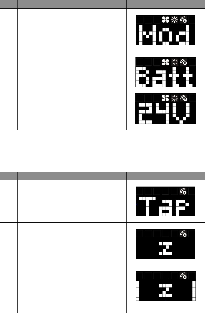
In the System Main (SYS) screen:
Press > to navigate to the Operation Mode (Mod)
screen. Press + or – to entry the setting.
2
If the screen displayed “Batt”, then the ZTS- 500US
will operate in FLiRS mode after inclusion into a
Z-Wave network.
If the screen displayed “24V”, then the ZTS- 500US
will operate in Always Listening mode after
inclusion into a Z-Wave network.
Press > or < to back to the previous screen.
Z-Wave Add (Include) / Remove (Exclude) into/from Z-Wave network
Add (Include) ZTS-500US to Gateway / Controller
Step
Procedure / Description LED indication
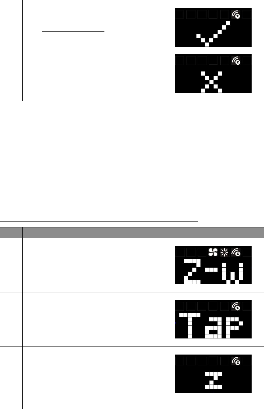
1
From the Standby screen, press > or < to navigate
to the Z-Wave screen and the Z-Wave LED will
continuously flash.
Tap + to include the ZTS-500US into the network.
2
There is a “z” animation during Z-Wave searching.
.
.
25
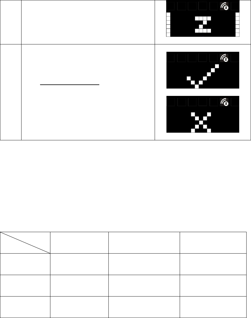
3
- The “✔” symbol will be displayed on screen
once the ZTS-500US is added into the network.
The Z-Wave disconnect icon will also be
removed from the standby screen.
- The “x” symbol will be displayed on screen if
there is no action (time out) or unable to include
the ZTS-500US into the network.
Notes:
1. It is recommended to perform the Remove/Exclude procedure before performing an
Add/Include procedure. This will ensure the ZTS-500US is not in any other Z-Wave network
which will disrupt the inclusion process.
2. If the inclusion process fails, try exclusion and/or resetting the ZTS-500US to factory default and
try inclusion again.
3. If the user navigates the menu from Brightness to the right side, the Z-Wave menu will be
skipped if the ZTS-500US is already included into the network and it will loop back to the
Standby screen by pressing the > key.
Remove (Exclude) ZTS-500US from Gateway / Controller
Step
Procedure / Description LED indication
1
Press and keep holding > or < for 3 seconds to
navigate to the System Main (SYS) screen.
On the Z-Wave (Z-w) screen, press + or – to entry
the setting.
2
Tap + to exclude or include ZTS-500US from or into
the network.
Press < to cancel and back to the previous screen.
3
There is a “z” animation during Z-Wave searching.
.
.
26
4
- The “✔” symbol will be displayed on screen
once the ZTS-500US is excluded from the
network.
The Z-Wave disconnect icon will also be
displayed in the standby screen.
- The “x” symbol will be displayed on screen if
there is no action (time out) or unable to
exclude the ZTS-500US from the network.
Note:
All Z-Wave configuration parameter values will keep no changes after excluding the unit from the
network, except for the association groups information. The ZTS-500US will retain the last selected
HVAC system type.
Support for Association Groups
ZTS-500US supports 3 association groups:
Association group_1
(Auto Report)
Association group_2
(Heater)
Association group_3
(Compressor)
Heating mode -
ON
(basic set command 0xFF)
OFF
(basic set command 0x00)
Cooling mode -
OFF
(basic set command 0x00)
ON
(basic set command 0xFF)
OFF -
OFF
(basic set command 0x00)
OFF
(basic set command 0x00)
Association group_1 (Auto report):
Association Group-1 is a default status report channel in Z-Wave+ lifeline requirement.
ZTS-500US will trigger AUTO report function if one of below status is changed.
a) Operation mode (Off, Heat, Cool, Auto)
b) Operation state (Heat on or off, Cool on or off)
c) Fan mode (Auto, On, High, Low)
d) Fan state (Fan on, Fan off)
e) Heat set point (report in precision of 0.5oC or 1oF)
Association group
Mode
27
f) Cool set point (report in precision of 0.5oC or 1oF)
g) Current room temperature (report in precision of 0.5oC or 1oF)
(It will trigger room temperature report if there is 2oF / 1oC [default] differ from last report.
You can change this setting by set the configuration parameter)
Notes:
Total 5 devices (nodes) can be assigned in total 3 association groups. Below table lists out the devices
(nodes) allocations in the 3 association groups.
No. of Node ID in
Association Group_1
No. of Node ID in
Association Group_2
No. of Node ID in
Association Group_3
1 (AUTO report) 0,1 or 2 nodes 0,1 or 2 nodes
Important:
Please do not associate heater and compressor devices in same association group because heater and
compressor device can’t turn on in simultaneously!
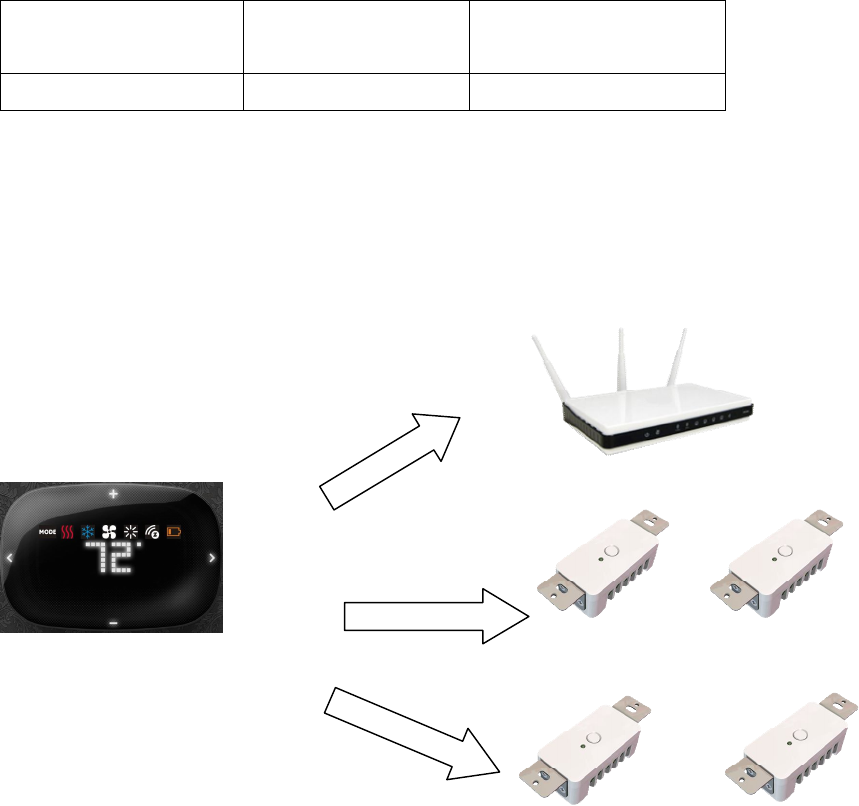
Example: Association groups setting
F-BW8170 (ZTS-500US)
F
-
BW8041 (ZFM
-
80)
(Node ID
-
B
)
F
-
BW8041 (ZFM
-
80)
(Node ID
-
C
)
Z
-
Wave Gateway
(Node ID
-
A
)
Association group_
2
for Heater
Association group_
3
for Compressor
Association group_
1
for Auto report to gateway
F
-
BW8041 (ZFM
-
80)
(Node ID
-
D
)
F
-
BW8041 (ZFM
-
80)
(Node ID
-
E
)

28
Z-Wave Configuration Parameters
Different users have different preferred settings of their thermostat, you may use the below
configuration parameters to change settings of corresponding functionality.
The size of Parameter number is 1 byte; Parameter value can be 1, 2, or 4 bytes.
Functions Parameter Number
Parameter value range
Scale of temperature 1 (0x01) 0 (0x00) = oC
1 (0x01) = oF (default)
Swing 2 (0x02) 1 (0x01) = 1 oF / 0.5 oC
2 (0x02) = 2 oF / 1.0 oC (default)
3 (0x03) = 3 oF / 1.5 oC
4 (0x04) = 4 oF / 2.0 oC
Differential 3 (0x03) 1 (0x01) = 1 oF / 0.5 oC
2 (0x02) = 2 oF / 1.0 oC (default)
3 (0x03) = 3 oF / 1.5 oC
4 (0x04) = 4 oF / 2.0 oC
Dead band
(On thermostats that
automatically control both
heating and cooling systems, a
dead band is a temperature
range in which neither system
turns on. The dead band
prevents the thermostat from
activating heat and cooling in
rapid succession. This
conserves energy by providing
a range of temperatures
requiring no energy
consumption)
4(0x04) Dead band value:
3(0x03)= 3oF/ 1.5oC
4(0x04)= 4oF/ 2.0oC (default)
5(0x05)= 5oF/ 2.5oC
6(0x06)= 6oF/ 3.0oC
Upper limit of Heat set point
(In order to save energy special
in motel service, advance user
or administrator can limit the
upper heat set point)
5 (0x05)
If in Heat
and Auto
mode:
=====================================
Unit in F:
Range from 41oF to (99oF - dead band)
Default = 95oF
Example 82oF; input = 820 (0x0334)
Unit in C:
Range from 5oC to (37oC – dead band)
Default = 35oC
E
xample 28
o
C; input = 280 (0x0118)
Lower limit of Cool set point
(In order to save energy special
6 (0x06)
If in Cool mode
and Auto Mode
:
=====================================
Unit in F:
Range from (41oF + dead band) to 99oF
Default = 45oF

29
in motel service, advance user
or administrator can limit the
lower cool set point)
E
xample 68
o
F; input = 680 (0x02A8)
Unit in C:
Range from (5oC + dead band) to 37oC
Default = 7oC
E
xample 20
o
C; input = 200 (0x00C8)
Reset filter counter 7 (0x07) 0 (0x00) (default)
Set filter counter 8 (0x08) 500 (0x01F4) to 4000 (0x0FA0) hours
500 (0x01F4) hours (default)
Resolution = 1 (0x0001) hours
Report filter counter
(read only)
9 (0x09) 0 (0x0000) to 9999 (0x270F) hours
Sensor temperature calibration
(This parameter is used to
change the display temperature
to match with your previous
thermostat, or to match
another thermostat already in
your home.
10 (0x0A) Temperature offset value.
Formula:
Display temperature = sensor reading value +
offset value
(unit = degree F)
0 (0x00) = 0oF (Default)
1 (0x01) = 1oF (0.5oC)
2 (0x02) = 2oF (1.0oC)
3 (0x03) = 3oF (1.5oC)
4 (0x04) = 4oF (2.0oC)
5 (0x05) = 5oF (2.5oC)
6 (0x06) = 6oF (3.0oC)
7 (0x07) = 7oF (3.5oC)
8 (0x08) = 8oF (4.0oC)
9 (0x09) = 9oF (4.5oC)
10 (0x0A) = 10oF (5.0oC)
-1 (0xFF) = -1oF (-0.5oC)
-2 (0xFE) = -2oF (-1.0oC)
-3 (0xFD) = -3oF (-1.5oC)
-4 (0xFC) = -4oF (-2.0oC)
-5 (0xFB) = -5oF (-2.5oC)
-6 (0xFA) = -6oF (-3.0oC)
-7 (0xF9) = -7oF (-3.5oC)
-8 (0xF8) = -8oF (-4.0oC)
-9 (0xF7) = -9oF (-4.5oC)
-10 (0xF6) = -10oF (-5.0oC)
LED brightness level 11 (0x0B) 1 (0x01) = Level-1 (dark)

30
2 (0x02) = Level-2 (middle) , default
3 (0x03) = Level-3 (bright)
Sleep timer 12 (0x0C) 3 (0x03) to 60 (0x3C) seconds,
255 (0xFF) = Always On
Step size = 1s,
Batt = 5s, default
24Vac = 60s, default
Repeat basic set counter
(Association Group A and B
only)
13 (0x0D) Value(X)
0 (0x00), 3 (0x03) to 255 (0xFF)
0 (0X00) = Disable, default
3 (0x03) to 255 (0xFF) minutes
(Thermostat sends “Basic Set” command to
its association node repeatedly in every X
minutes)
Trigger AUTO report if room
temperature is different from
last report.
(It will report room
temperature only)
*User can use this function to
enhance batteries service life.
14 (0x0E) 0 (0x00) = disable AUTO report if room
temperature is different from last report.
AUTO report if room temperature is different
from last report.
Delta change is >=
1 (0x01) = 1oF (0.5oC), default value if
powered by 24Vac
2 (0x02) = 2oF (1.0oC), default value if
powered by battery
3 (0x03) = 3oF (1.5oC)
4 (0x04) = 4oF (2.0oC)
5 (0x05) = 5oF (2.5oC)
6 (0x06) = 6oF (3.0oC)
7 (0x07) = 7oF (3.5oC)
8 (0x08) = 8oF (4.0oC)
AUTO report by time interval.
(It will report room
temperature only)
*User can use this function to
enhance batteries service life.
15 (0x0F) 0 (0x00) = disable AUTO report function (by
time interval), default
AUTO report timer:
1 (0x01) = 0.5 hr
2 (0x02) = 1.0 hr
3 (0x03) = 1.5 hrs
4 (0x04) = 2.0 hrs
5 (0x05) = 2.5 hrs
6 (0x06) = 3.0 hrs
7 (0x07) = 3.5 hrs
8 (0x08) = 4.0 hrs
31
9 (0x09) = 4.5 hrs
10 (0x0A) = 5.0 hrs
11 (0x0B) = 5.5 hrs
12 (0x0C) = 6.0 hrs
13 (0x0D) = 6.5 hrs
14 (0x0E) = 7.0 hrs
15 (0x0F) = 7.5 hrs
16 (0x10) = 8.0 hrs
Sensor temperature calibration example:
If sensor reading value = 77oF, offset value = -2OF
Display temperature = sensor reading value + offset value
= 77-2oF = 75oF
If using decimal input: Parameter no. = 10; Parameter value = -2
If using hexadecimal input: Parameter no. = 0x0A; Parameter value = FE (Size >= 1 byte)
Reset ZTS-500US to Factory Default Settings
Step Procedure / Description LED indication
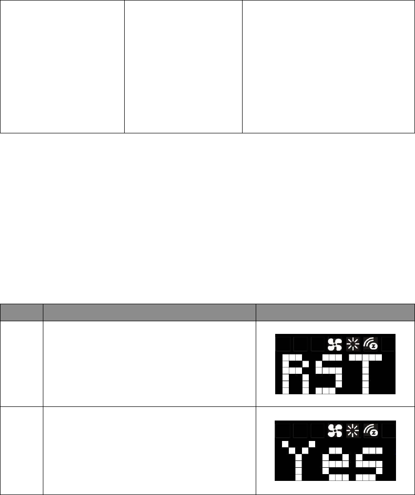
1
Press and keep holding > or < for 3 seconds to
navigate to the System Main (SYS) screen.
Press > to navigate to the Reset (RST) screen.
Press + or – to entry the setting.
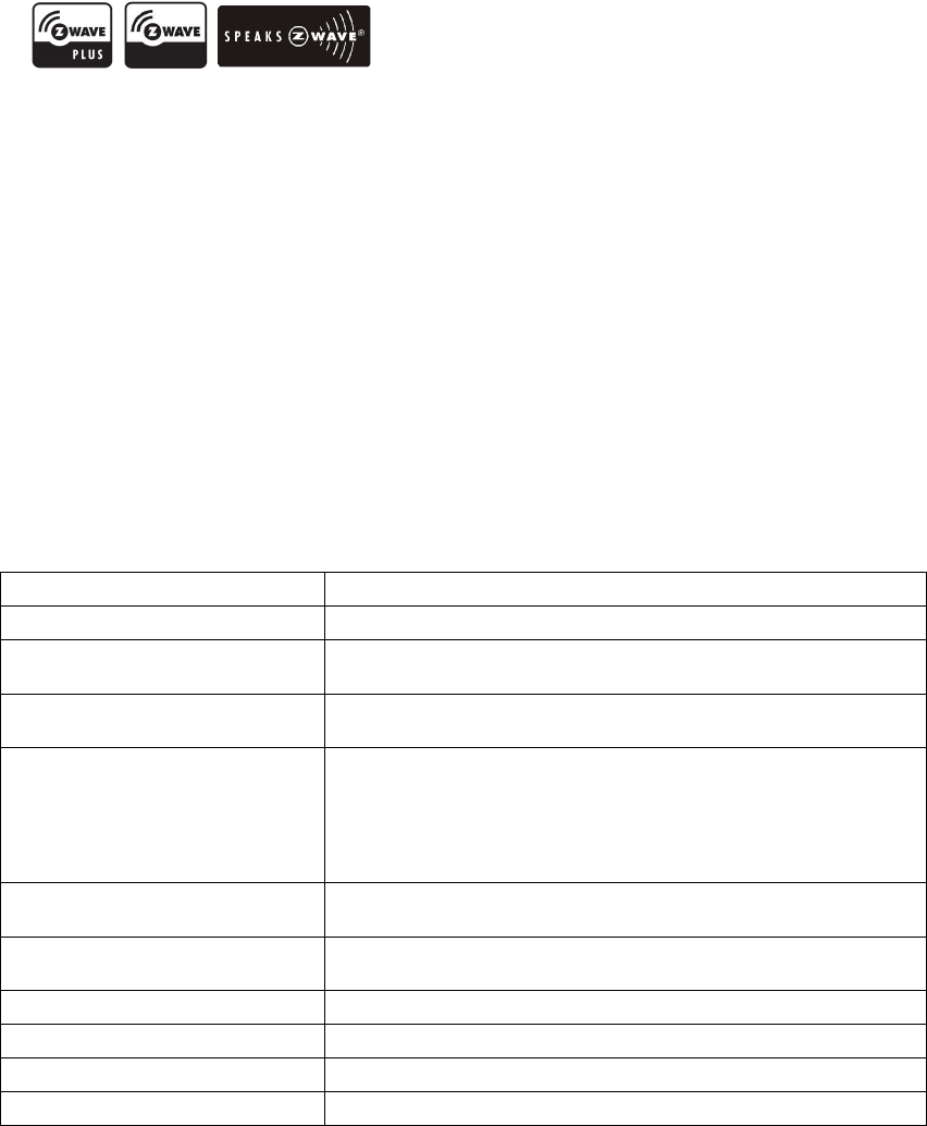
2
Press + or - to select Yes.
Press and keep holding > for 2 seconds to
confirm your selection.
Press < to cancel and back to the previous
screen.
Note:
If the user performs a Reset to Factory Default Settings, all settings, Z-Wave configuration
parameter values and association groups information will reset to default. The ZTS-500US will retain
the last selected HVAC system type.
32
Frequently Asked Questions
Q Why won’t my ZTS-500US work with the Z-Wave devices purchased in another country?
A Due to differing regulations in different countries, Z-Wave products from different regions are
set to different frequencies. Before purchasing new devices, be sure to check if the devices are
compatible in your region.
Q Do I need an electrician to install a ZTS-500US in my home?
A It is strongly recommended that a qualified technician install this product.
Q How do I know which product is compatible with my ZTS-500US?
A The ZTS-500US is compatible with any Z-Wave controller or gateway that has the control
capability for “Thermostat” devices. All Z-Wave products are also labelled with the Z-Wave logos
shown below.
Q Can I use 2 or more ZTS-500US in my house? If so, what is the max. units?
A Yes, you can use multiple ZTS-500USs in a single home. The maximum number of units depends
on the capabilities of the gateways and controllers. For example, different gateways can support
up to 8, 16, or 32 ZTS-500US on a given network.
Q What is the recommended battery type for the ZTS-500US and what is estimated batteries
service life?
A Alkaline batteries are recommended for the ZTS-500US.
Batteries service life is very dependent on the amount of usage per day. With normal use,
approximate battery service life is 1 year while operated in FLiRS mode.
If you are using battery power as the main power source or as a back-up while AC power is down
and the ZTS-500US is in Z-Wave Always Listening mode, the battery will drain very fast (battery
will only survive 3-5 days).
Technical Specifications
Model no. BW8170US (ZTS-500US)
RF frequency 908.4MHz (ZTS-500US)
RF operating distance
up to 1
32
ft
(40m)
out
door li
ne of sight, in unobstructed
environment
Z-Wave association group
S
upports 3 association
group
s, max. 5 nodes ID can be assigned to
these association groups.
LED and button
C
urved w
hite LEDs
display
Resolution: 18 x 6 dots
VA: 64mm x 28mm
Status icons: 7
“<”, “>”, “+” and “–“ control buttons and LEDs
Powered by
Dry battery AA x
4
pcs
or
24 VAC +/- 20% 50/60Hz
Relay contact
Voltage
:
24 VAC 50/60 Hz
Current: 1A Max. (inductive)
Temperature display resolution 1°F / 0.5 °C
Temperature measurable range 32 – 99 °F / 0 – 37 °C
Temperature Setting range 41-99 °F / 5-37 °C
Temperature Operating: 32 – 122 °F / 0 – 50 °C
33
Storage
:
23
–
140 °F /
-
5
–
60 °C
Dimension (L x H x T) 160mm x 100mm x 28mm
Weight 190g (Batteries excluded)
Checking Accessories
After opening the cover of the packing box, check that the following accessories are included.
ZTS-500US
Screw + Wall Anchor x 2pcs
AA batteries x 4pcs (optional)
User Manual
Warranty sheet
Wireless Information
This device has an open-air line-of-sight transmission distance of 132 feet (40m) which complies
with the Z-Wave standards. Performance can vary depending on the amount of objects in between
Z-Wave devices such as walls and furniture. Every Z-Wave device set up in your network will act as a
signal repeater allowing devices to talk to each other and find alternate routes in the case of a
reception dead spot.
Radio frequency limitations:
1. Each wall or object (i.e.: refrigerator, bookshelf, large TV, etc) can reduce the maximum range
of 65 feet (20m) by up to 20 to 30%.
2. Plasterboard and wooden walls block less of the radio signal then concrete, brick or tile walls
which will have more of an effect on signal strength.
3. Wall mounted Z-Wave devices will also suffer a loss of range if they are housed in metal
junction boxes which could also reduce the range by up to 20 to 30%.
Maintenance
Do not expose your unit to dust, strong sunlight, humidity, high temperatures or mechanical shocks.
1. Do not use old and new batteries together as old batteries tend to leak.
2. Do not use corrosive or abrasive cleansers on your unit.
3. Keep the unit dust free by wiping it with a soft, dry cloth.
4. Do not disassemble the unit, it contains no user-serviceable parts.
FCC Notice
This device complies with Part 15 of the FCC rules. Operation is subject to the following two
conditions:
(1) This device may not cause harmful interference, and
(2) This device must accept any interference received, including interference that may cause
undesired operation.
This equipment has been tested and found to comply with the limits for a Class B digital device,
pursuant to Part 15 of the FCC Rules. These limits are designed to provide reasonable protection
against harmful interference in a residential installation. This equipment generates, uses and can
radiate radio frequency energy and, if not installed and used in accordance with the instructions,
34
may cause harmful interference to radio communications. However, there is no guarantee that
interference will not occur in a particular installation. If this equipment does cause harmful
interference to radio or television reception, which can be determined by turning the equipment off
and on, the user is encouraged to try to correct the interference by one or more of the following
measures:
- Reorient or relocate the receiving antenna.
- Increase the separation between the equipment and receiver.
- Connect the equipment into an outlet on a circuit different from that to which the receiver is
connected.
- Consult the dealer or an experienced radio/TV technician for help.
Notice : Changes or modifications to this unit not expressly approved by the party responsible for
compliance could void the user authority to operate the equipment.
IC Notice
This device complies with Industry Canada licence-exempt RSS standard(s). Operation is
subject to the following two conditions:
(1) This device may not cause interference, and
(2) This device must accept any interference, including interference that may cause undesired
operation of the device.
Le présent appareil est conforme aux CNR d'Industrie Canada applicables aux appareils radio
exempts de licence. L'exploitation est autorisée aux deux conditionssuivantes:
(1) l'appareil ne doit pas produire de brouillage, et
(2) l'utilisateur de l'appareil doit accepter tout brouillage radioélectrique subi, même si le
brouillage est susceptible d'en compromettre le fonctionnement.
Warnings
- Do not modify the unit in any way.
- Risk of fire.
- Risk of electrical shock.
- Risk of burns.
- Do not dispose of electrical appliances as unsorted municipal waste, use separate collection
facilities. Contact your local government for information regarding the collection systems
available.
- There is no user serviceable parts in this unit.
Caution
- Risk of explosion if battery is replaced by an incorrect type.
- Dispose of used batteries according to the instructions.