Remotec Technology BW8370 Z-Extender User Manual
Remotec Technology Limited Z-Extender
UserManual.wiki
>
Remotec Technology
>
BW8370 User Manual
User Manual
Navigation menu
Upload a User Manual
Namespaces
Wiki Guide
HTML
PDF
Info
Views
User Manual
Discussion / Help
Navigation
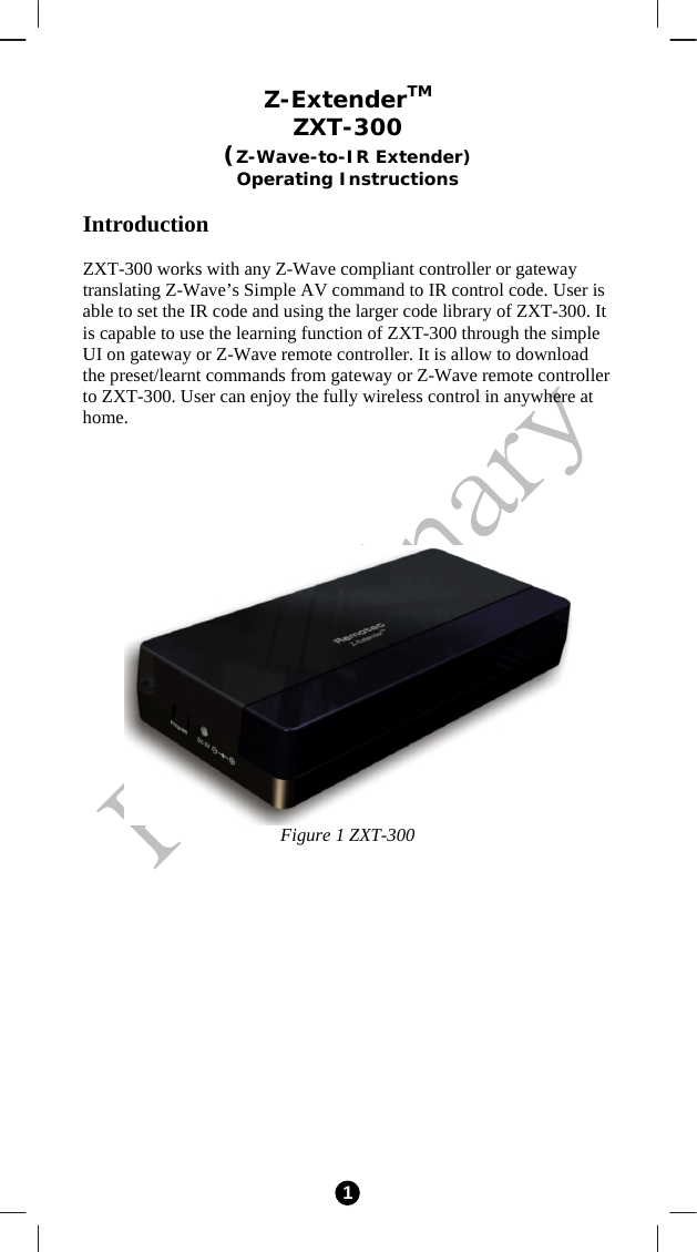
![2 ZXT-300 Operations Before using the ZXT-300, please read the [INSTALLATION] if it is need to mount the ZXT-300 to a wall. Power up the ZXT-300 by the supplied AC/DC adaptor. L CAUTION − Be sure to always use the supplied AC/DC adaptor. − Do not try to power up other device with the supplied AC/DC adaptor. This could damage the AC/DC adaptor or the connected device. Configurations Figure 2 PROG Key and IR Ports of ZXT-300 IR LearningLED Indication IR Port 1 IR Port Output“PROG” button](https://usermanual.wiki/Remotec-Technology/BW8370/User-Guide-1414031-Page-2.png)