Remotec Technology BW8370 Z-Extender User Manual
Remotec Technology Limited Z-Extender
User Manual
1
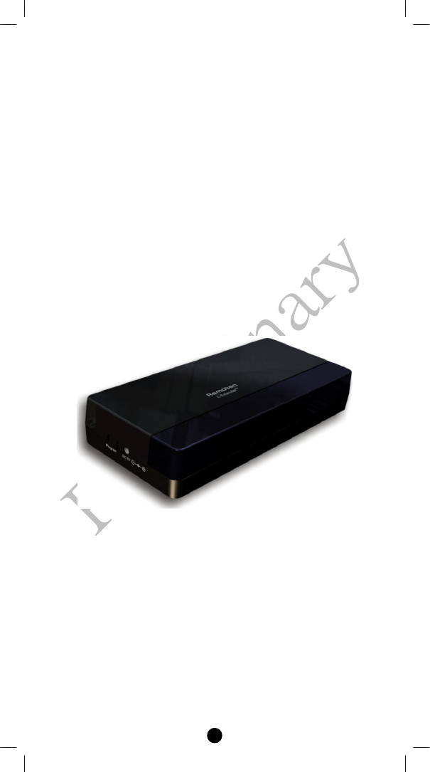
Z-ExtenderTM
ZXT-300
(Z-Wave-to-IR Extender)
Operating Instructions
Introduction
ZXT-300 works with any Z-Wave compliant controller or gateway
translating Z-Wave’s Simple AV command to IR control code. User is
able to set the IR code and using the larger code library of ZXT-300. It
is capable to use the learning function of ZXT-300 through the simple
UI on gateway or Z-Wave remote controller. It is allow to download
the preset/learnt commands from gateway or Z-Wave remote controller
to ZXT-300. User can enjoy the fully wireless control in anywhere at
home.
Figure 1 ZXT-300
2
ZXT-300 Operations
Before using the ZXT-300, please read the [INSTALLATION] if it is
need to mount the ZXT-300 to a wall. Power up the ZXT-300 by the
supplied AC/DC adaptor.
L CAUTION
− Be sure to always use the supplied AC/DC adaptor.
− Do not try to power up other device with the supplied AC/DC
adaptor. This could damage the AC/DC adaptor or the
connected device.
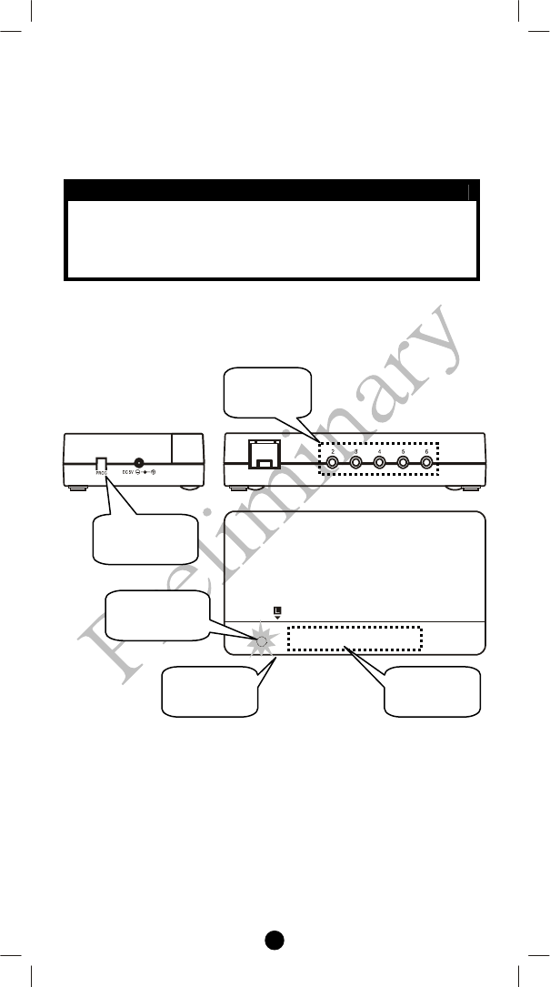
Configurations
Figure 2 PROG Key and IR Ports of ZXT-300
IR
Learnin
g
LED
Indication
IR Port 1
IR Port
Out
p
ut
“PROG”
button
3
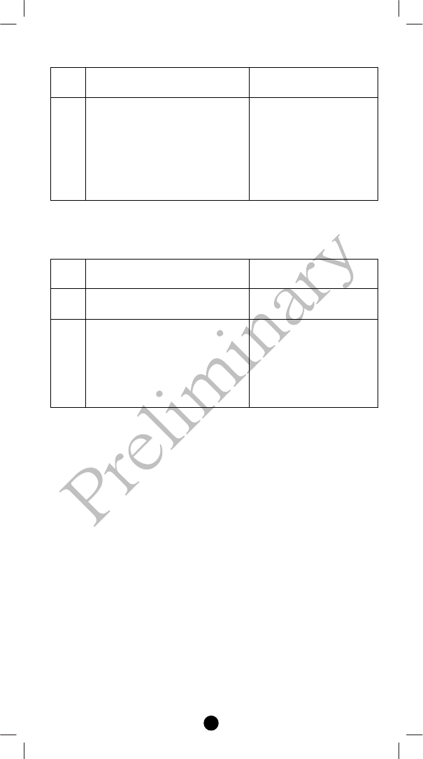
Change Z-Wave-to-IR Channel (EP) on ZXT-300
Step Setup Key LED Indication Status
on ZXT-300
1
Press and hold PROG button on
the ZXT-300 for 3seconds to
switch the EP (1->2->3->4-
>5->6->1->2...)
• LED flashes 1 = EP1
• LED flashes 2 = EP2
• LED flashes 3 = EP3
• LED flashes 4 = EP4
• LED flashes 5 = EP5
• LED flashes 6 = EP6
How to get the NIF “Node Information Frame” on ZXT-
300
Step Setup Key LED Indication Status
on ZXT-300
1 ZXT-300 switch to Z-Wave-to-
IR Channel (EP1)
• LED flashes 1 times
then keep on
2
Press the PROG button on the
ZXT-300
(EP1 will response “NIF”
EP2, EP3, EP4, EP5, EP6 will
response “Multi-channel
capability report”)
• LED flashes 1 times
then keep on
(ZXT-300 will report the
supported command
class)
Reset ZXT-300 to factory default
Press and hold “PROG” button for 10seconds on ZXT-300. LED will
flashing until reset process is completed.
4
INSTALLATION
MOUNTING THE ZXT-300 TO A WALL
MOUNTING LOCATION PRECAUTIONS
• Before mounting, check the material and structure of the mounting
location. If the location does not have the proper material or
structure, the ZXT-300 can fall and cause an injury.
• Use commercial items that best match the wall structure and
material for the screws and other fixtures.
• Do not mount near a kitchen counter, humidifier, or other location
in which it can be exposed to smoke or steam. Doing so could
cause a fire or electrical shock.
• Do not mount in locations with high humidity or large amounts of
dust. Doing so could cause a fire or electrical shock.
• Do not mount to locations subject to high temperatures, high
humidity, or exposed to water. Doing so could cause a fire or
electrical shock.
• Do not mount to locations subject to large amounts of vibration,
large jolts, or large forces. These could cause an injury if the ZXT-
300 falls and breaks.
MOUNTING PROCEDURE PRECAUTIONS
• Do not modify parts or use the ZXT-300 in ways other than its
intended use. Doing so could cause the ZXT-300 to fall and result
in an injury.
• Be sure to fully check that there are no electrical wires or pipes
inside the wall before mounting.
• If any of the screws are loose, the ZXT-300 can fall and cause an
injury. Do not mount the ZXT-300 with the screws still loose.
• Check that the two screws mounted to the wall are fully inserted
into the key holes of the ZXT-300. Otherwise, the ZXT-300 can
fall and cause an injury.
• Do not mount the ZXT-300 so that it sticks out from the wall edge.
It could get hit by people’s bodies or objects and cause an injury.
• Remotec will not be liable for any accidents or injuries that occur
due to improper mounting or handling.
• When mounting, be careful not to get your fingers pinched or
injure your hands.
MOUNTING PROCEDURE
The ZXT-300 can be mounted to a wall or wooden racks using the two
key holes in the bottom case. The ZXT-300 can be oriented
horizontally or vertically. Mount in the best way for your installation
conditions.
Note 1: The reception sensitivity varies depending on the antenna
direction. Find the direction providing the best reception by
adjusting the antenna direction before mounting the ZXT-300.
5
Note 2: No screws are provided for mounting to a wall.
Note 3: Before mounting to a wall, be sure to fully read the precautions.
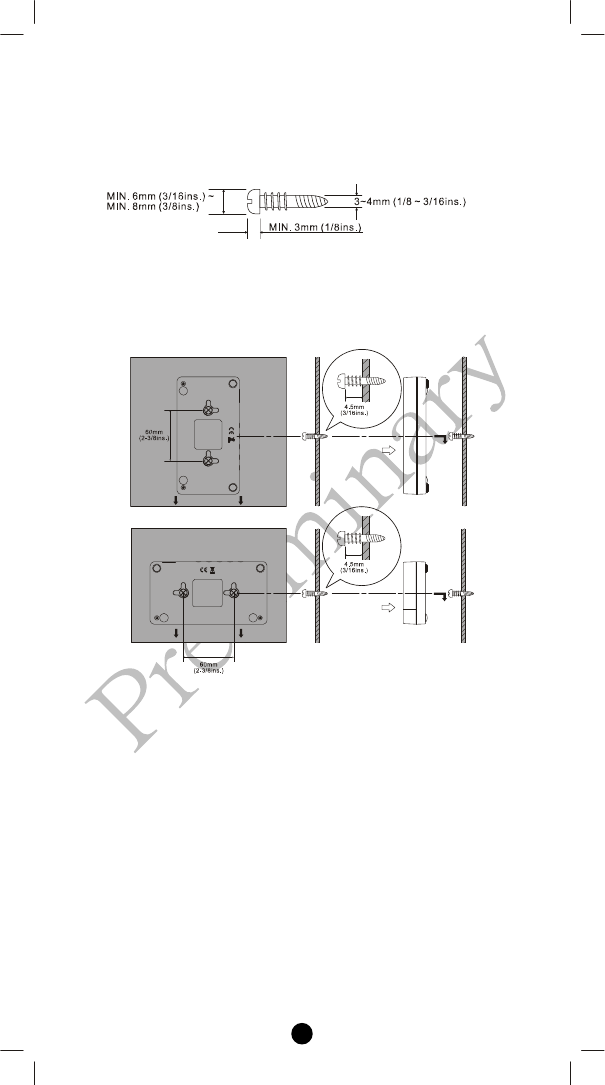
1. Obtain two screws suitable for the wall strength and material. The
screw size is shown in the figure below.
2. The positional relationship between the ZXT-300 key holes and
the screw mounting positions are shown in the figure below.
Note 1: When mounting the screws to the wall, leave a space
between the wall and screw cap as shown in the figure.
3. Insert the ZXT-300 key holes onto the two screws mounted to the
wall, and then slide downward to secure in place.
4. After securing the ZXT-300 to the wall, connect the AC/DC
adaptor and cables to the ZXT-300.
Note 1: Check that the ZXT-300 is firmly secured to the wall.
Note 2: Insert the AC/DC adaptor and IR emitter cable so that
they are firmly connected to the ZXT-300.
5. When removing the ZXT-300 from the wall, lift up the ZXT-300,
then pull it towards you.
6
WIRELESS INFORMATION
Wireless range:
This device has an open air line of sight transmission distance of 100
feet which complies with the Z-Wave standards. Performance can vary
depending on the amount of objects in between Z-Wave devices such
as walls and furniture. Every Z-Wave device set up in your house will
act as a signal repeater allowing devices to talk to each other and find
alternate routes in the case of a reception dead spot.
Radio frequency limitations:
1. Each wall or object (i.e.: refrigerator, bookshelf, large TV, etc) can
reduce the maximum range of 65 feet by up to 25 to 30%.
2. Plasterboard and wooden walls block less of the radio signal then
concrete, brick or tile walls which will have more of an effect on
signal strength.
3. Wall mounted Z-Wave devices will also suffer a loss of range as
they are housed in metal junction boxes which could reduce the
range by up to 25 to 30%.
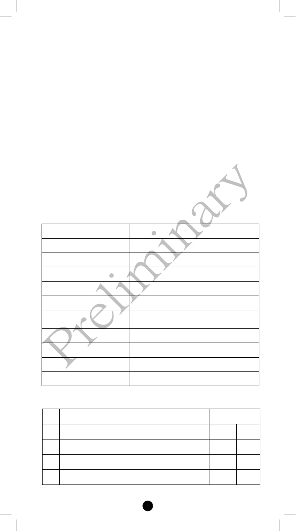
TECHNICAL SPECIFICATIONS
Model no. BW8370US (ZXT-300US)
Model no. BW8370EU (ZXT-300EU)
RF Frequency 908.4MHz (US); ZXT-300US
RF Frequency 868.4MHz (EU); ZXT-300EU
IR Frequency Up to 455kHz
IR Learning Max 100 commands
Max. Range up to 100ft outdoor line of sight, in
unobstructed environment
Power DC 5V 100mA
Humidity 10~85%, non-condensing
Dimension (LxWxT) 139 x 75 x 28.5 mm
Weight 90g
Control and Support Command Class
ZXT-300
Item Command Class Control Support
1 COMMAND_CLASS_CONFIGURATION No Yes
2 COMMAND_CLASS_CONFIGURATION_V2 No Yes
3 COMMAND_CLASS_VERSION No Yes
7
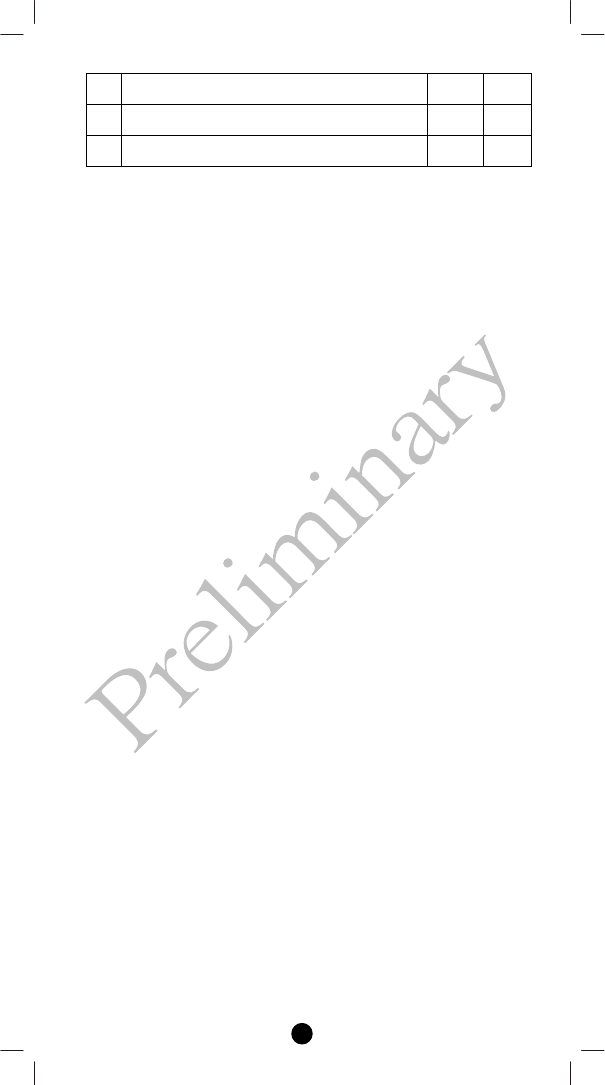
4 COMMAND_CLASS_MANUFACTURER_SPECIFIC No Yes
5 COMMAND_CLASS_SIMPLE_AV_CONTROL, No Yes
6 Multi Channel Command Class, version 2 No Yes
Z-Wave protocol stack revision: Ver. 5.02 patch 3
CHECKING THE ACCESSORIES
After opening the cover of the packing box, check that the following
accessories are included.
• ZXT-300: Z-Wave-to-IR Extender
• Power adaptor: 100~240Vac input, 5Vdc 1000mA
(for ZXT-300)
• IR Emitting Cable: 3.5mm Mono plug cable x 3pcs
(for ZXT-300)
• Quick Reference Guide
• Code List
FCC NOTICE
This equipment has been tested and found to comply with the limits for
a Class B digital device, pursuant to Part 15 of the FCC Rules. These
limits are designed to provide reasonable protection against harmful
interference in a residential installation. This equipment generates, uses
and can radiate radio frequency energy and, if not installed and used in
accordance with the instructions, may cause harmful interference to
radio communications. However, there is no guarantee that interference
will not occur in a particular installation.
If this equipment does cause harmful interference to radio or television
reception, which can be determined by turning the equipment off and
on, the user is encouraged to try to correct the interference by one or
more of the following measures:
• Reorient or relocate the receiving antenna.
• Increase the separation between the equipment and receiver.
• Connect the equipment into an outlet on a circuit different from
that to which the receiver is connected.
• Consult the dealer or an experienced radio/TV technician for help.
8
WARNINGS
Changes or modifications not expressly approved by the party
responsible for compliance could void the user's authority to operate
the equipment.
- RISK OF FIRE
- RISK OF ELECTRICAL SHOCK
- RISK OF BURNS
- The socket-outlet shall be installed near the equipment
and shall be easily accessible.
- Use only power supplies listed in the user instructions.
F820-8370-000
Printed in China
www.remotec.com.hk