Remotec Technology BW8377 Z-Wave to AC IR Extender User Manual 8377 v16b manual F820 8377 0000
Remotec Technology Limited Z-Wave to AC IR Extender 8377 v16b manual F820 8377 0000
UserManual.wiki
>
Remotec Technology
>
BW8377 User Manual
User Manual
Navigation menu
Upload a User Manual
Namespaces
Wiki Guide
HTML
PDF
Info
Views
User Manual
Discussion / Help
Navigation
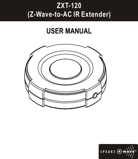
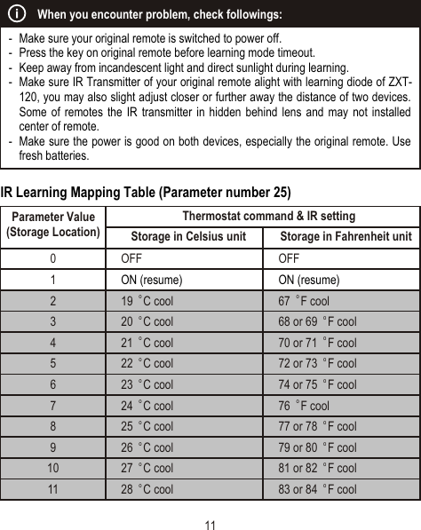
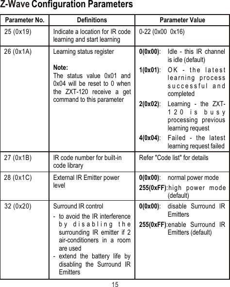
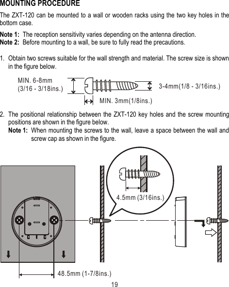
![TM Z-Extender ZXT-120 (Z-Wave-to-AC IR Extender)IntroductionThe ZXT-120 is a Z-Wave to IR extender for air-conditioner (AC), (Figure 1), it works with any Z-Wave compliant gateway or controller by translating Z-Wave Thermostat Commands to AC IR control code. User can select the IR code from the built-in code library of ZXT-120, or use learning function, by using Z-Wave Configuration Commands according to the parameter table. ZXT-120 is also with built-in temperature sensor which allows gateway or controller to get the current room temperature.ZXT-120 can be configured as either "Frequently Listening Routing Slaves" FLiRS (if you are using battery) or "Always Listening" (if you are using 5Vdc adaptor) before inclusion process. Refer to Glossary for definition of "FLiRS" and "Always Listening" mode.ZXT-120 supports Network Wide Inclusion (NWI) and Explore Frames. It also supports Z-]Wave networks with multiple gateways and controllers. Once the configuration and setup is complete, the gateway or controller can use Z-Wave "Thermostat commands class" to control their IR-controlled air-conditioner through the ZXT-120.2Figure 1 ZXT-120](https://usermanual.wiki/Remotec-Technology/BW8377/User-Guide-2326480-Page-3.png)
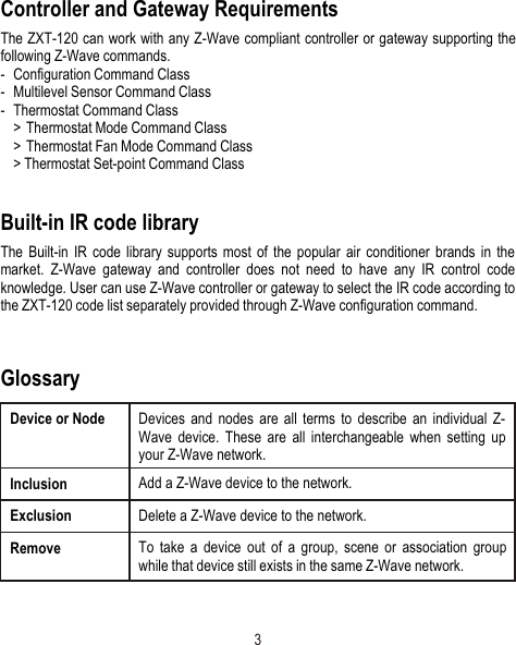
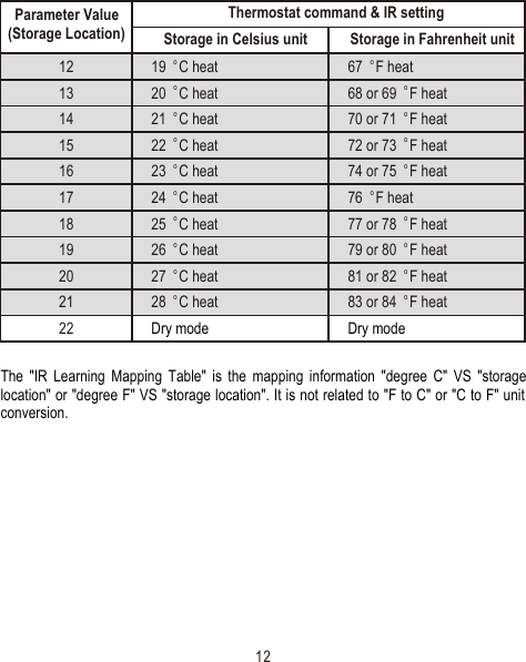
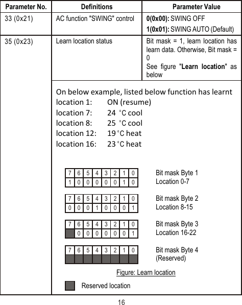
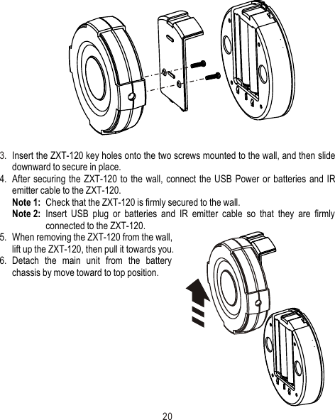
![6Setup and OperationsBefore using the ZXT-120, please read the [INSTALLATION] if you need to mount the ZXT-120 to a wall. Power up the ZXT-120 by the USB Power 5Vdc or Dry battery AAA x 3pcs.- Plug-in 5Vdc power into the USB socket if operated at Always Listening mode. Or- Install 3xAAA batteries if operated at FLiRS mode. - Please refer to the section of [MOUNTING PROCEDURE].- Remove the battery cover on the back of your ZXT-120 battery chassis.- Mount the battery cover into the main unit with 2 screws.- Check the polarity of the batteries and the "+/-" marks inside the battery compartment.- Insert the batteries. - Push the battery cover and main unit back in place.(Please carefully read through the following then store the manual for future reference.)Listening Mode (default mode is FLiRS)ZXT-120 can be configured as either "Frequently Listening Routing Slaves" FLiRS (if you are using battery) or "Always Listening" (if you are using 5Vdc adaptor) before inclusion process. Refer to Glossary for definition of "FLIRS" and "Always Listening" mode.Important:It is not allowed to changing ZXT-120 listening mode without exclusion process (do not change ZXT-120 listening mode while ZXT-120 is included in a network).ƒ{- Use new batteries of the recommended type and size only.ƒ{- Never mix used and new batteries together.ƒ{- To avoid chemical leaks, remove batteries from the ZXT-120 if you do not intend to use the remote for an extended period of time.- Dispose of used batteries properly; do not burn or bury them.CAUTION (battery and power adaptor safety)](https://usermanual.wiki/Remotec-Technology/BW8377/User-Guide-2326480-Page-7.png)