Remotesolution MC85A00 Zigbee Module User Manual Users manual 2
Remote Solution Co., Ltd. Zigbee Module Users manual 2
Users manual 2
< 1 페이지 >
Zigbee Module(MC85A00) Manual
Monitoring Device
Measuring instrument
MC85A00
(Zigbee Module)
Main Module
1. Introduction : Zigbee Module(MC85A00) is data transfer module, using in measuring
instrument. Measuring intstrument contains Natural conditions such as temperature and
humidity
2. Features
This module receives the command of the main module from the measuring equipment and sends
the measured data to the monitoring device or transmits the data received from the monitoring
device to the main module.
This module is a device that enables measurement equipment to communicate wirelessly
(ZIGBEE), and interacts with the main module via UART.
It also has a built-in 2.4-MHz amplifier, which helps to transfer data over longer distances.
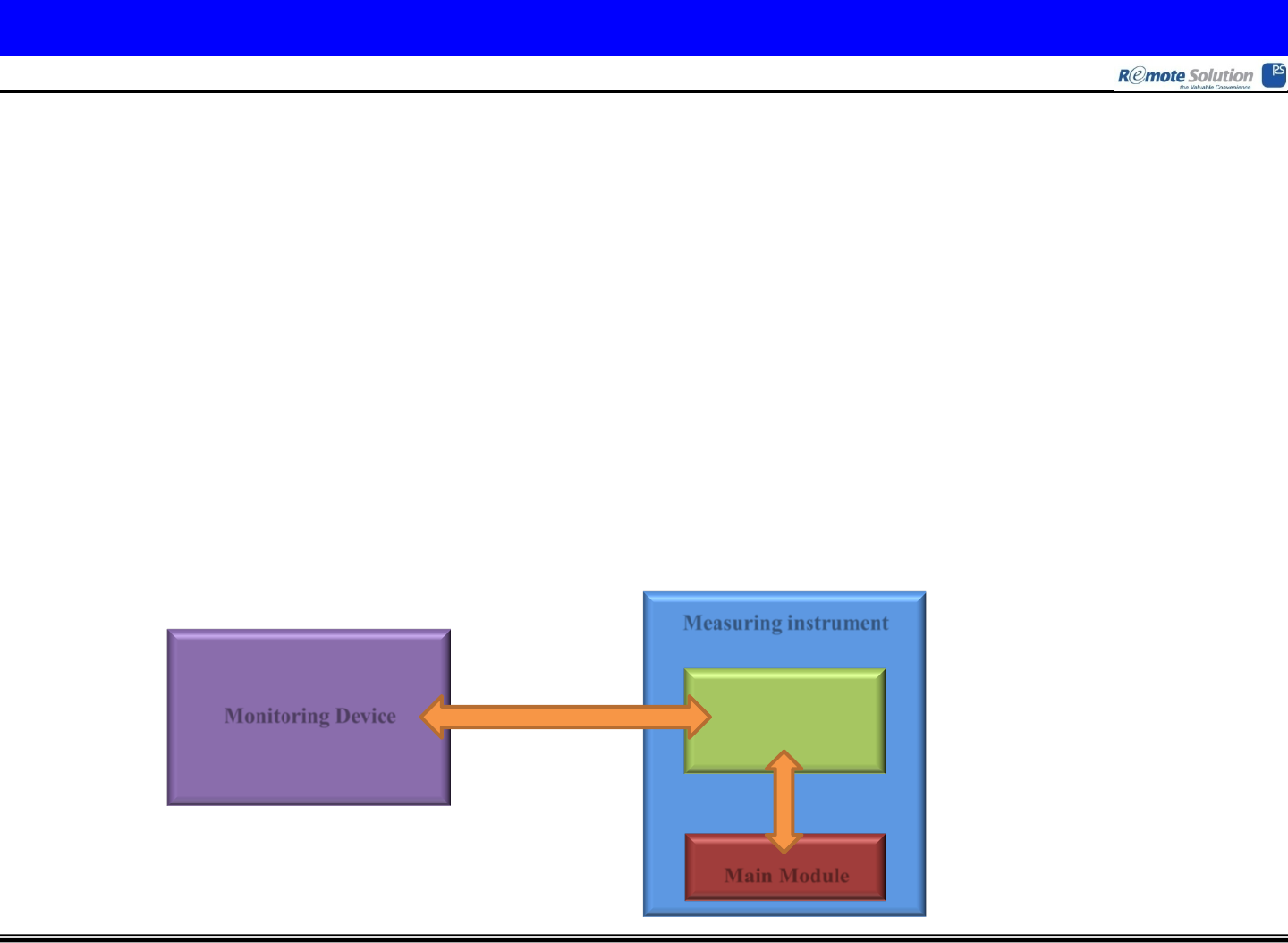
3. Operation sequence
First, monitoring device request measured data to measuring instrument using ZIGBEE.
Second, zigbee module(MC85A00) request measured data to main module using UART.
Third, main module send measured data to zigbee module(MC85A00) using UART.
Forth, zigbee module(MC85A00) send measured data to monitoring device using ZIGBEE.
< 2 페이지 >
Zigbee Module(MC85A00) Manual
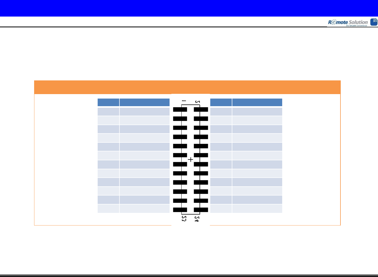
Pin Configuration (Top View)
Pin No. Pin Name
1 MCU Reset
3 DIO[23] LID
5 DIO[24] Relay
7 DIO[02] DPSW1
9 DIO[03] DPSW2
11 DIO[04] DPSW3
13 DIO[08] LED1
15 DIO[09] LED2
17 DIO[10] LED3
19 DIO[11] LED4
21 VDD 3V3
23 GND
Pin No. Pin Name
2 DIO[29] UART Tx
4 DIO[28] UART Rx
6 DIO[30] UART CLK
8 DIO[17] SPI SCLK
10 DIO[19] SPI MOSI
12 DIO[18] SPI MISO
14 DIO[14] SPI CSN
16 DIO[05] I2C SDA
18 DIO[06] I2C SCL
20 DIO[25] MRESET
22 GND
24 GND
4. Hardware information : All control of the Zigbee module is done in CC2630 (TI).
CC2592 (TI) is used to increase the communication distance.
Between the main module and this module are connected through a pin header and a pin header
socket(24pin), each of which has its own function. (See the figure below)
< 3 페이지 >
Zigbee Module(MC85A00) Manual
5. Electrical Characteristics
- Absolute Maximum Supply Voltage(DC) : -0.3V ~ 4.1V
- Absolute Maximum Storage Temperature Range : -40˚C ~ 150˚C
- Recommended Operating Voltage : 3.3V (Operable from 1.8V to 3.8V.)
- Receiver sensitivity : -100 dBm (Typ.)
- Receiver saturation : +4 dBm (Typ.)
- Frequency error tolerance : >200ppm
- RSSI dynamic range : 100 dB
- RSSI accuracy : ±4 dB
- Output power : -21 ~ 5 dBm
- Error vector magnityde : 2% (Typ.)
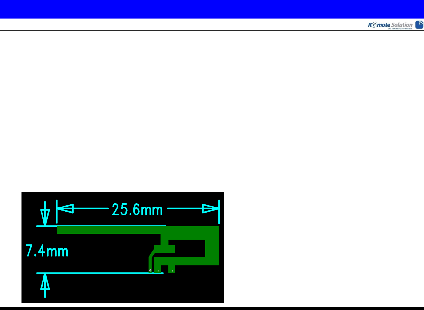
6. Antenna Information
- Material : FR-4
- Thickness : ½ oz
- Surface Treatment : OSP

FCC Information
This device complies with part 15 of the FCC Results. Operation is subject to the
following two conditions :
(1) This device may not cause harmful interface, and
(2) This device must accept any interference received, including interference that
may cause undesired operation.
Note: This equipment has been tested and found to comply with the limits for CLASS B digital device,
pursuant to Part 15 of FCC Rules. These limits are designed to provide reasonable protection against harmful
interference when the equipment is operated in a commercial environment This equipment generates, uses
and can radiate radio frequency energy and, if not installed and used in accordance with the instructions,
may cause harmful interference to radio communications. However, there is no guarantee that interference
will not occur in a particular installation. If this equipment does cause harmful interference to radio or
television reception, which can be determined by turning the equipment off and on, the user is encouraged
to try correct the interference by one or more of the following measures:
1.1. Reorient or relocate the receiving antenna.
1.2. Increase the separation between the equipment and receiver.
1.3. Connect the equipment into an outlet on a circuit different from that to which receiver is connected.
1.4. Consult the dealer or experienced radio/TV technician for help.
WARNING
Changes or modifications not expressly approved by the manufacturer could void the
user’s authority to operate the equipment.
End product labelling
The label for end product must include “Contains FCC ID: TX4MC85A00”.
“CAUTION : Exposure to Radio Frequency Radiation.
This equipment complies with FCC radiation exposure limits set forth for an uncontrolled environment. This
equipment must be installed and operated with minimum distance of 20 cm between the radiator and your
body. This transmitter module is authorized only for use in device where the antenna may be installed such
that 20 cm may be maintained between the antenna and users.”