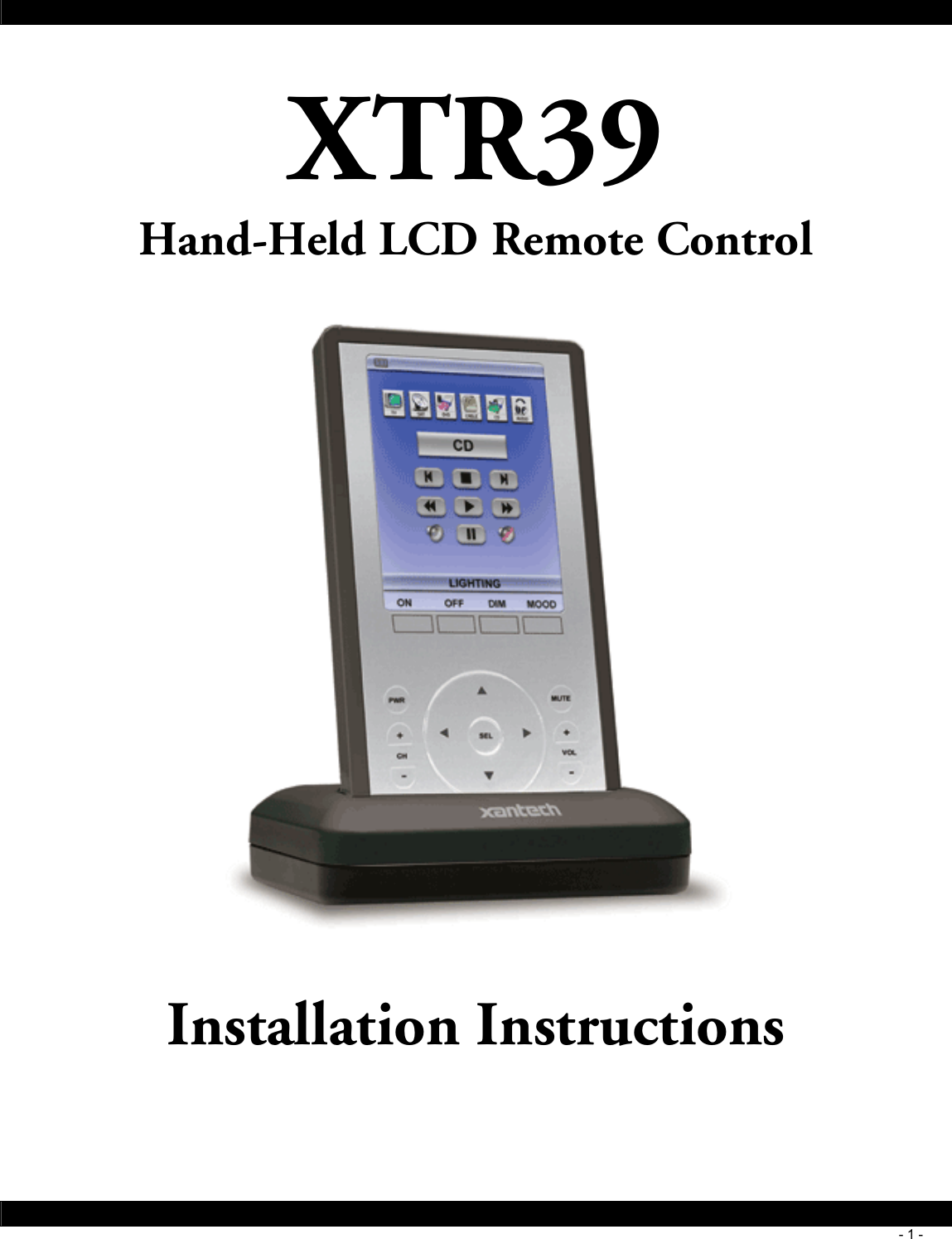
Remotesolution RH60A Color LCD Touch Screen Universal Remote Control User Manual 08905073X3
Remote Solution Co., Ltd. Color LCD Touch Screen Universal Remote Control 08905073X3
UserManual.wiki
>
Remotesolution
>
RH60A User Manual
>
Users Manual
Contents
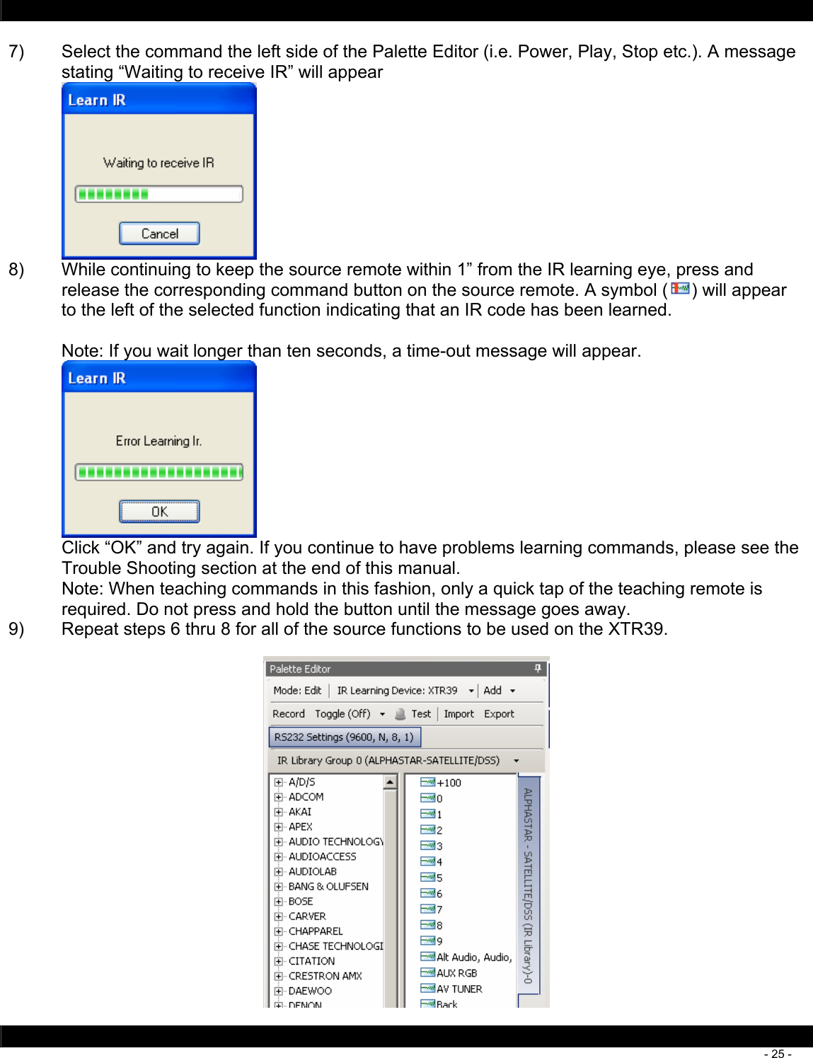
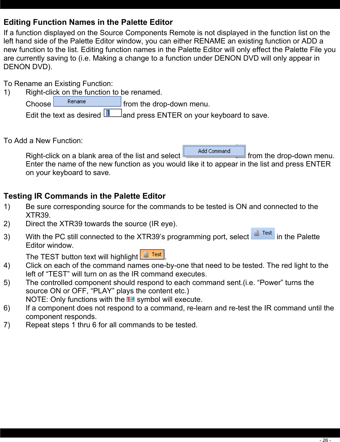
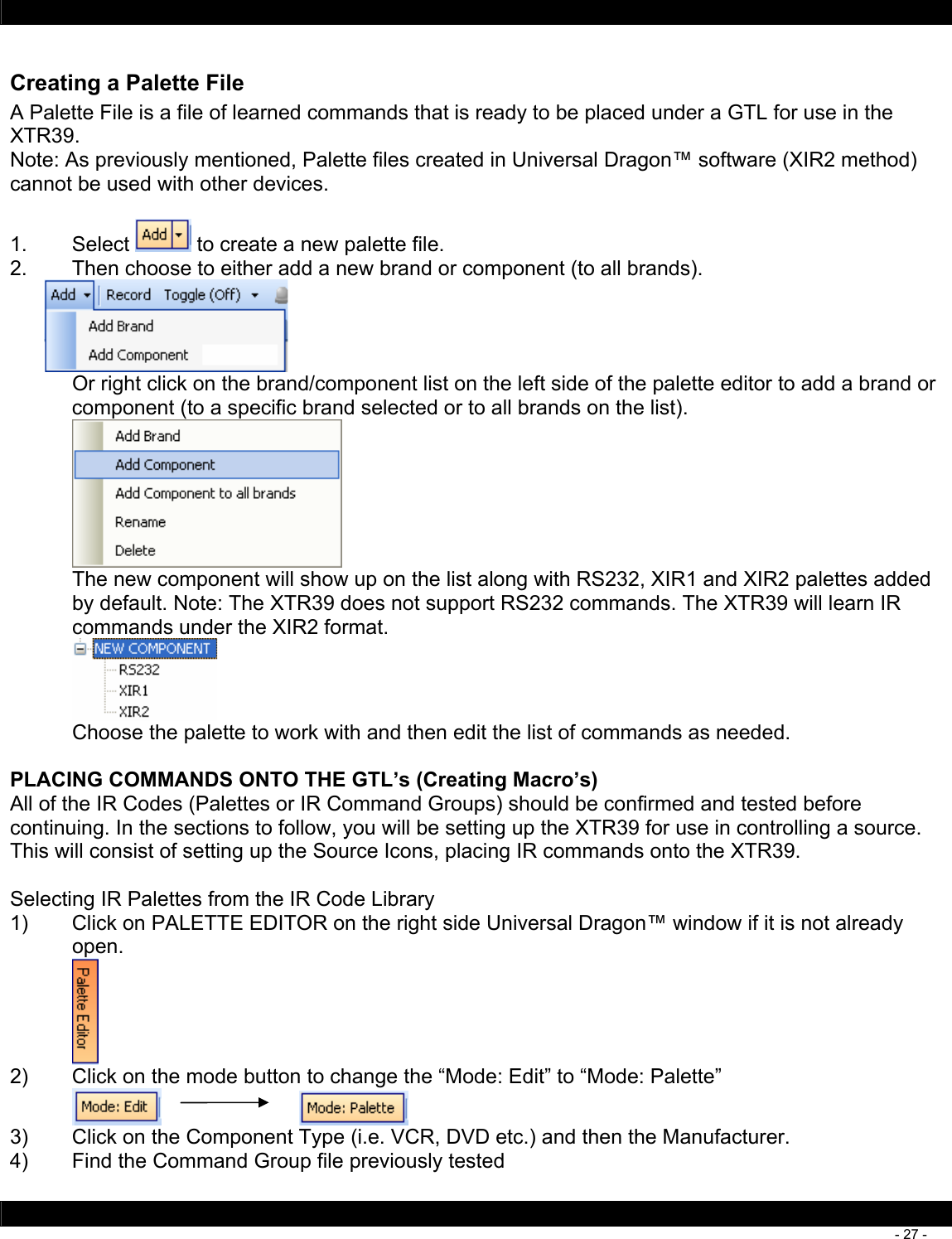
1.
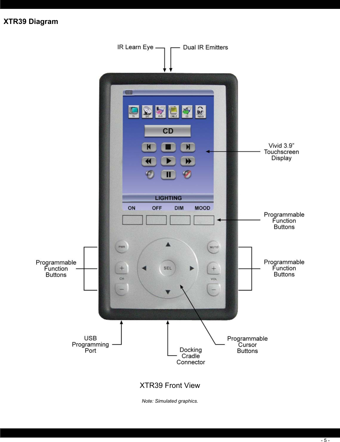
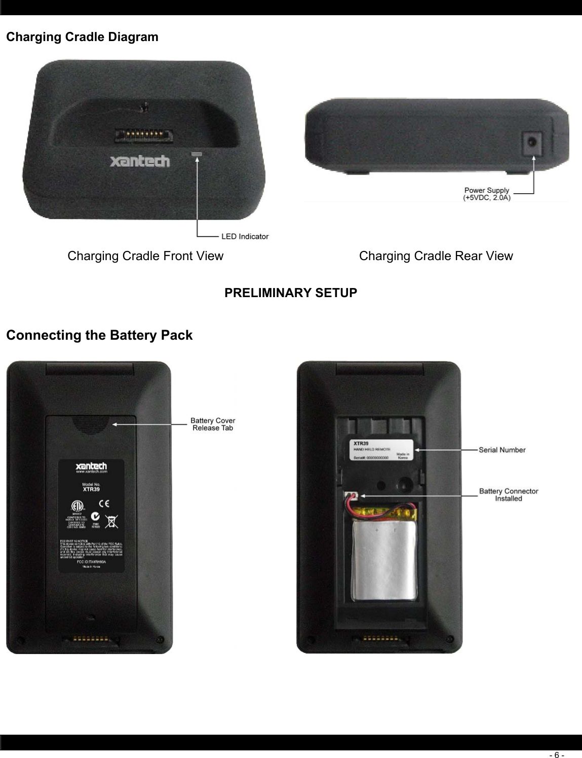
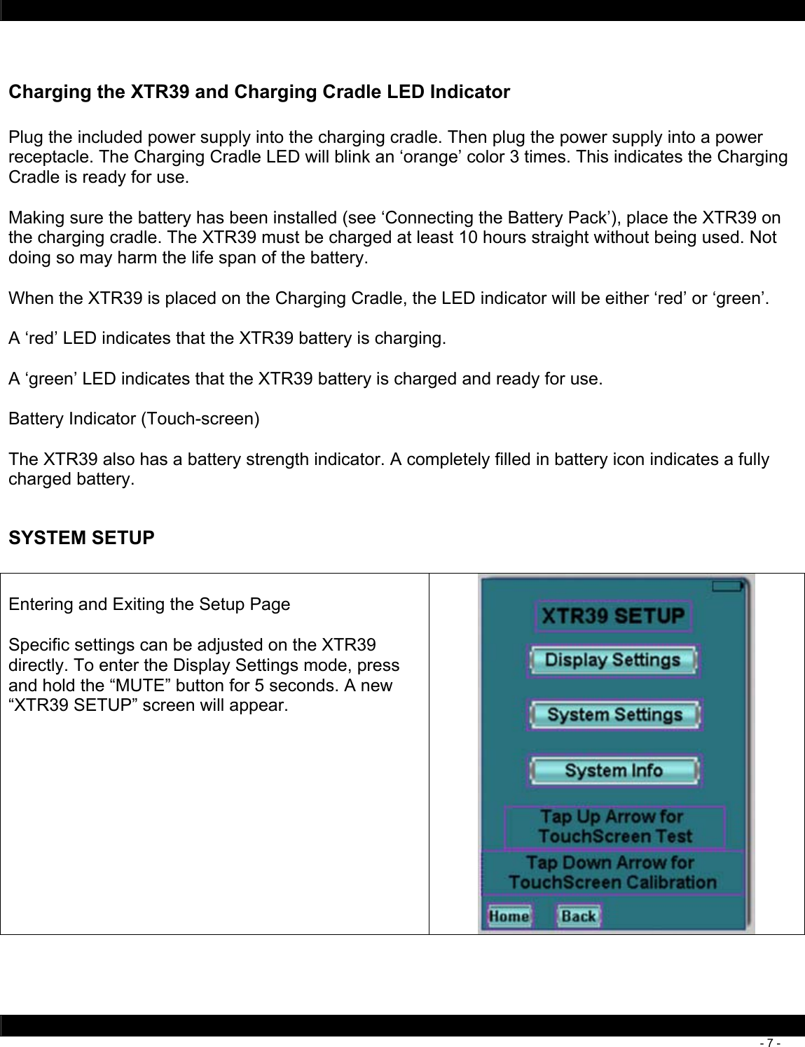
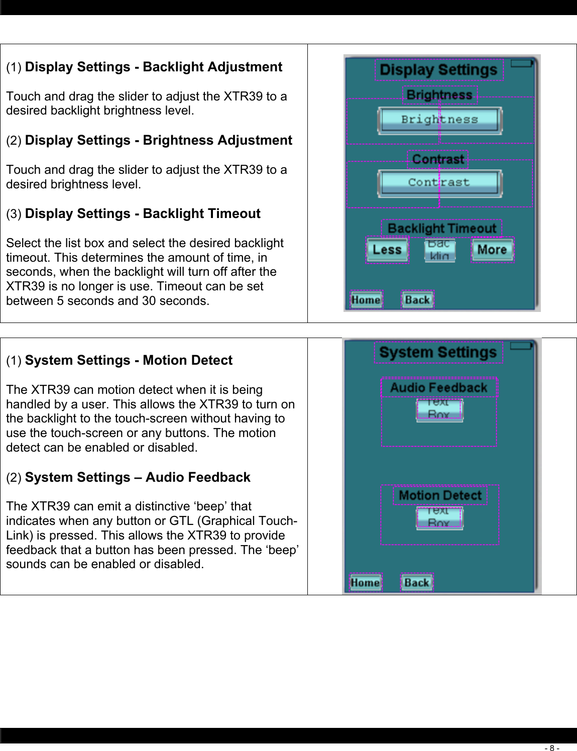
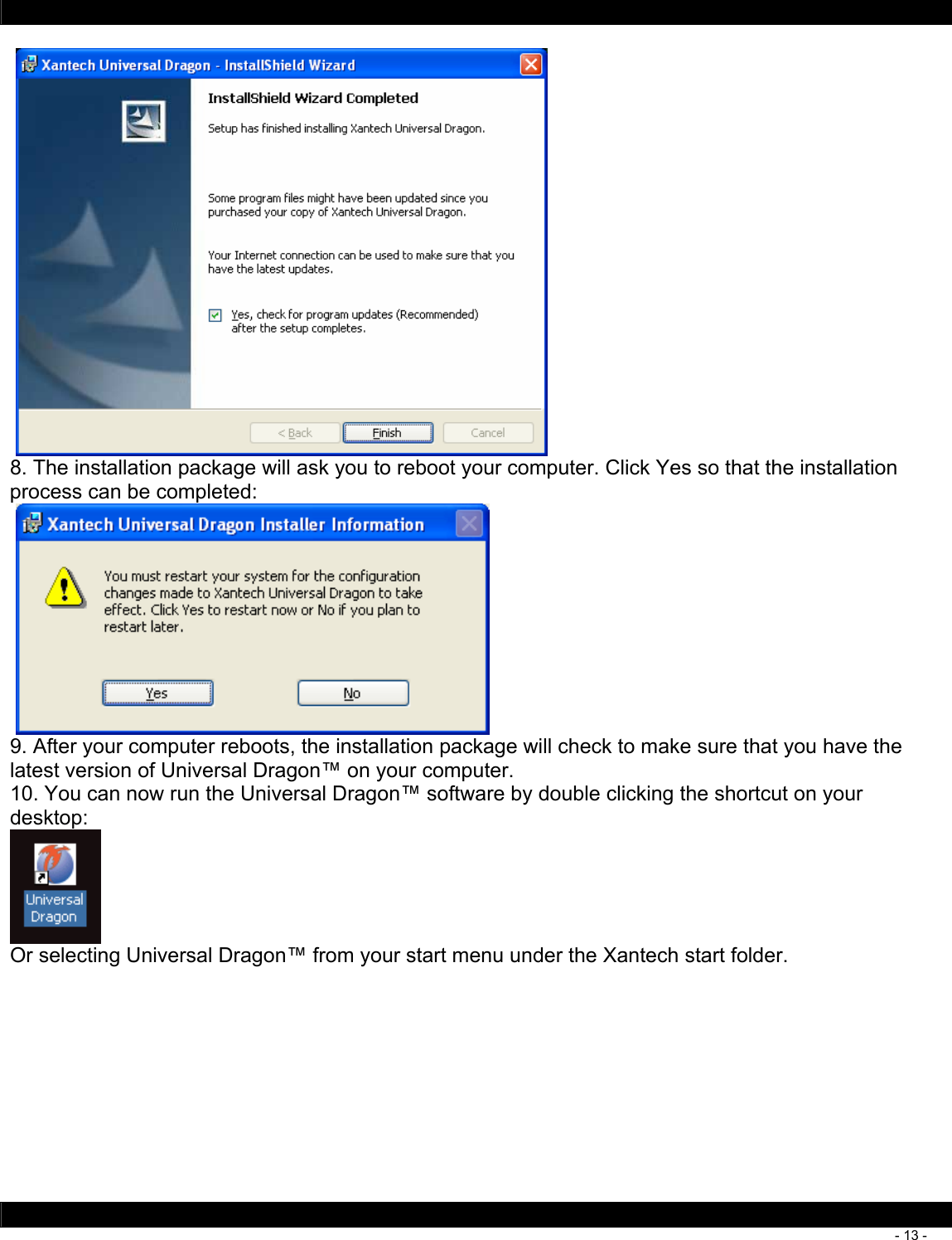
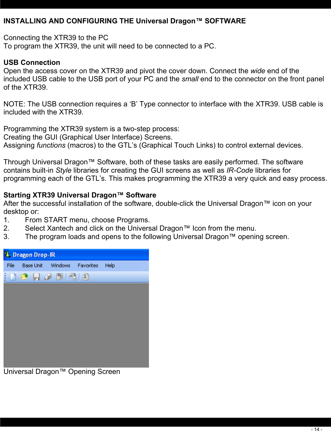
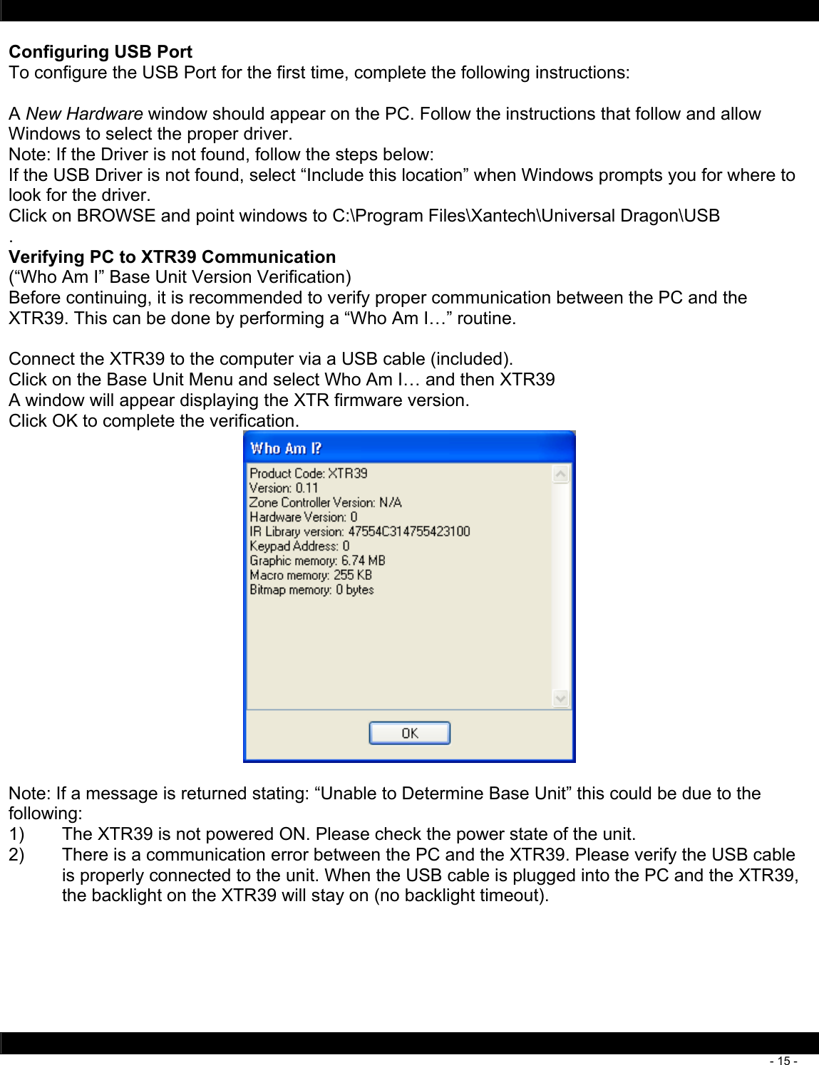
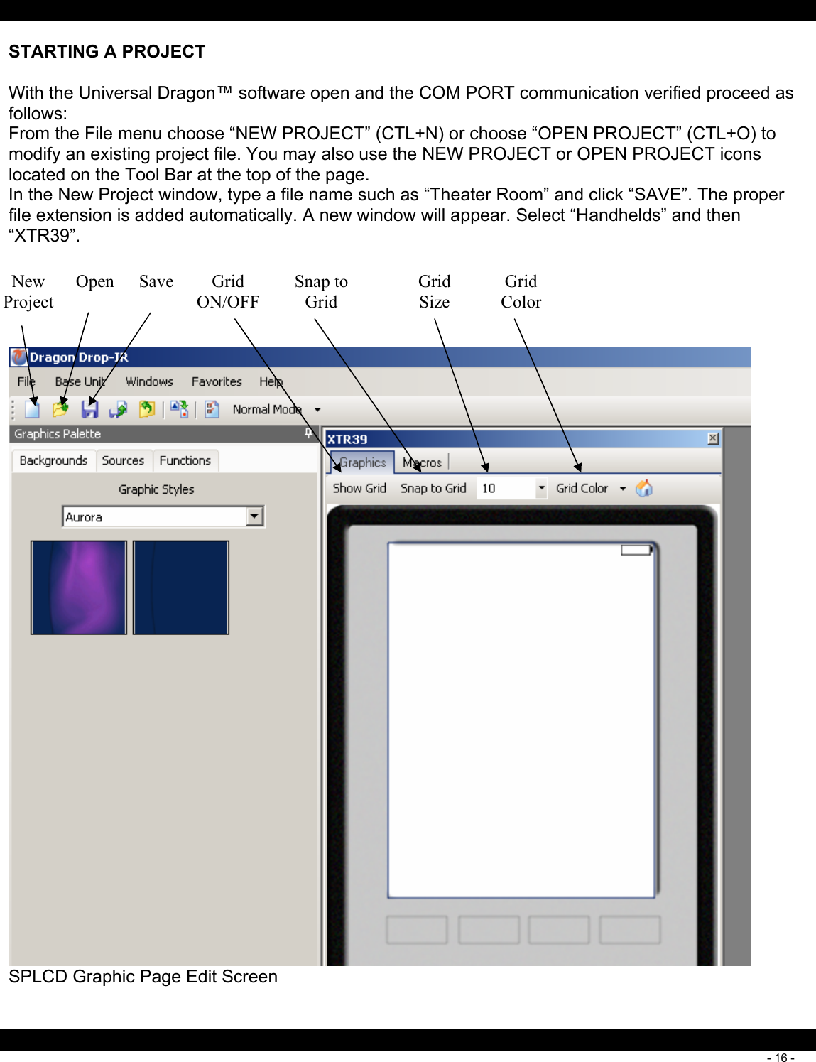
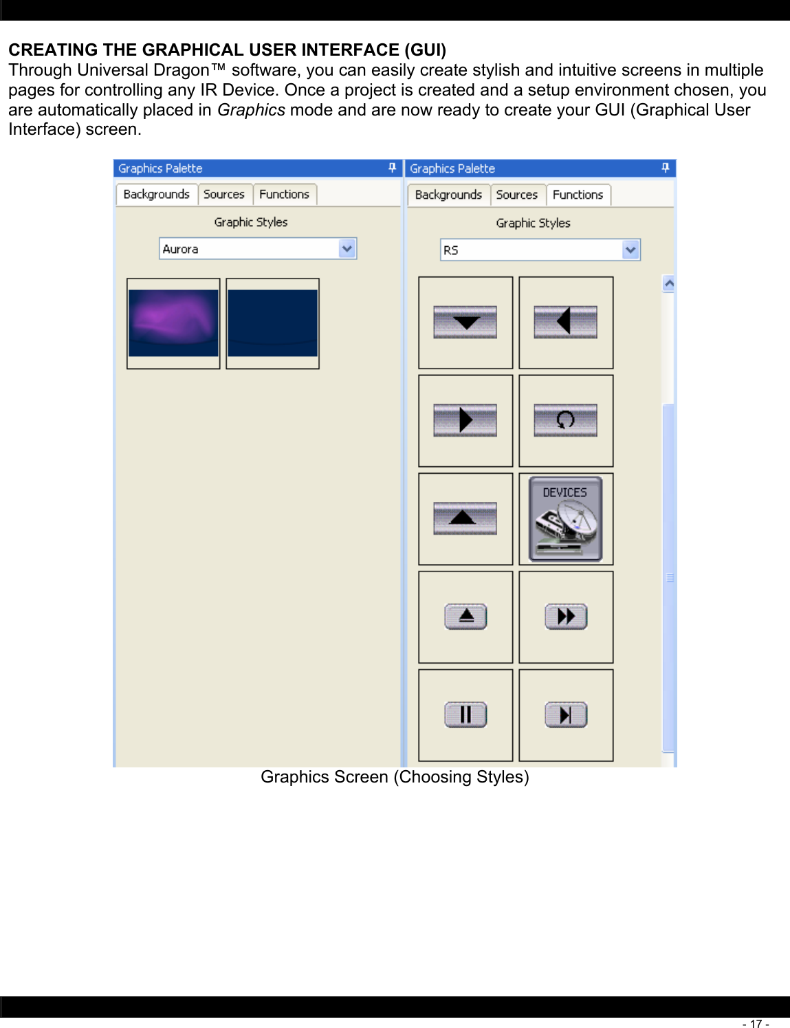
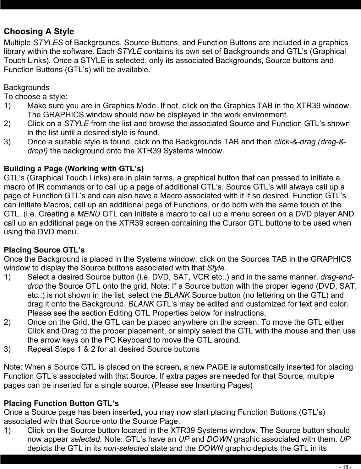
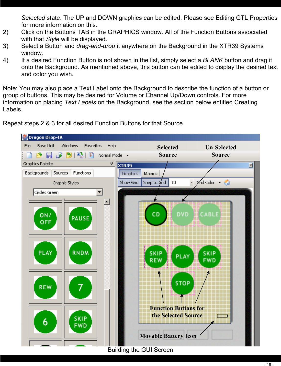
Users Manual
2.
Users Manual II
Users Manual
Navigation menu
Upload a User Manual
Namespaces
Wiki Guide
HTML
PDF
Info
Views
User Manual
Discussion / Help
Navigation