Renault 2013 Clio Cup Users Manual ManualsLib Makes It Easy To Find Manuals Online!
2013 Clio Cup 2013_clio_cup
2015-02-10
: Renault Renault-2013-Clio-Cup-Users-Manual-360708 renault-2013-clio-cup-users-manual-360708 renault pdf
Open the PDF directly: View PDF ![]() .
.
Page Count: 35
B. PRESENTATION
2013 USER MANUAL

98CUP_2013 Release
C-2
B PRESENTATION
CONTENTS
B PRESENTATION 2
B.1 IDENTIFICATION 4
B.1.1 ROLL CAGE 4
B.1.2 CHASSIS NUMBER 4
B.1.3 HOLOGRAMS 5
B.1.4 MARKINGS 5
B.2 DIMENSIONS 6
B.3 CAPACITIES 7
B.4 GENERAL CHARACTERISTICS 8
B.5 HANDLING 9
B.5.1 LIFTING 9
B.5.2 TOWING 9
B.6 USING THE CAR 10
B.6.1 FACIA SWITCH PANEL : XAP_SWT98 10
B.6.2 STEERING WHEEL SWITCH PANEL : XAP_STER98 11
B.6.3 DASHBOARD: COSWORTH ICD 01D-032954-RST 12
B.6.3.1 PAGES 12
B.6.3.1.1 DRIVER PAGE 1 : RACE PAGE 12
B.6.3.1.2 DRIVER PAGE 2 : QUALIFICATION PAGE 13
B.6.3.1.3 DRIVER PAGE 3 : CIRCUIT MAP PAGE 14
B.6.3.1.4 DIAGNOTIC PAGE 1 : ENGINE DIAGNOSTIC 14
B.6.3.1.5 DIAGNOSTIC PAGE 2 : GEARBOX DIAGNOSTIC 16
B.6.3.1.6 DIAGNOSTIC PAGE 3 : BRAKE / CHASSIS DIAGNOSTIC 17
B.6.3.1.7 DIAGNOSTIC PAGE 4 : CBNT DIAGNOSTIC (PAGE 1/2 : STATUS) 17
B.6.3.1.8 DIAGNOSTIC PAGE 5 : CBNT DIAGNOSTIC (PAGE 1/2 : STATES) 18
B.6.3.2 CHANGING PAGES 19
B.6.3.3 LEDS / SHIFTLIGHTS 19
B.6.3.4 ALARMS DISPLAYED ON THE DASHBOARD 20
B.6.3.4.1 MAIN ALARMS (CATEGORY A) 20
B.6.3.4.2 SECONDARY ALARMS (CATEGORY B) 21
B.6.3.4.3 ALARMS AND THRESHOLD 21
B.6.4 BASIC PROCEDURES 22
B.6.4.1 POWER-UP 22
B.6.4.2 STARTING 22
B.6.4.3 TURNING OFF THE ENGINE 23
B.6.4.4 SWITCHING OFF THE POWER SUPPLY 23
B.6.4.5 CHANGING GEARS 23
B.6.4.6 PIT LIMITER 23
B.6.4.7 CONTROLLING THE RAIN LIGHT 24
B.6.4.8 RESETTING THE CHASSIS SENSORS 25

98CUP_2013 Release
C-3
B.6.5 ADJUSTING THE DRIVING POSITION 26
B.6.5.1 ADJUSTING THE STEERING WHEEL 26
B.6.5.2 ADJUSTING THE SEAT 26
B.6.6 VENTILATION 27
B.7 SAFETY EQUIPMENT 28
B.7.1 FIRE EXTINGUISHER 28
B.7.2 CIRCUIT BREAKER 31
B.7.3 OTHER SAFETY EQUIPMENT 31
B.7.4 PASSENGER SEAT 32
B.8 BALLAST 32
B.9 APPENDIX 33
B.9.1 LIST OF MARKED PARTS 33
B.9.2 REPLACEMENT OF MECHANICAL COMPONENTS 35
98CUP_2013 Release
C-4
B.1 IDENTIFICATION
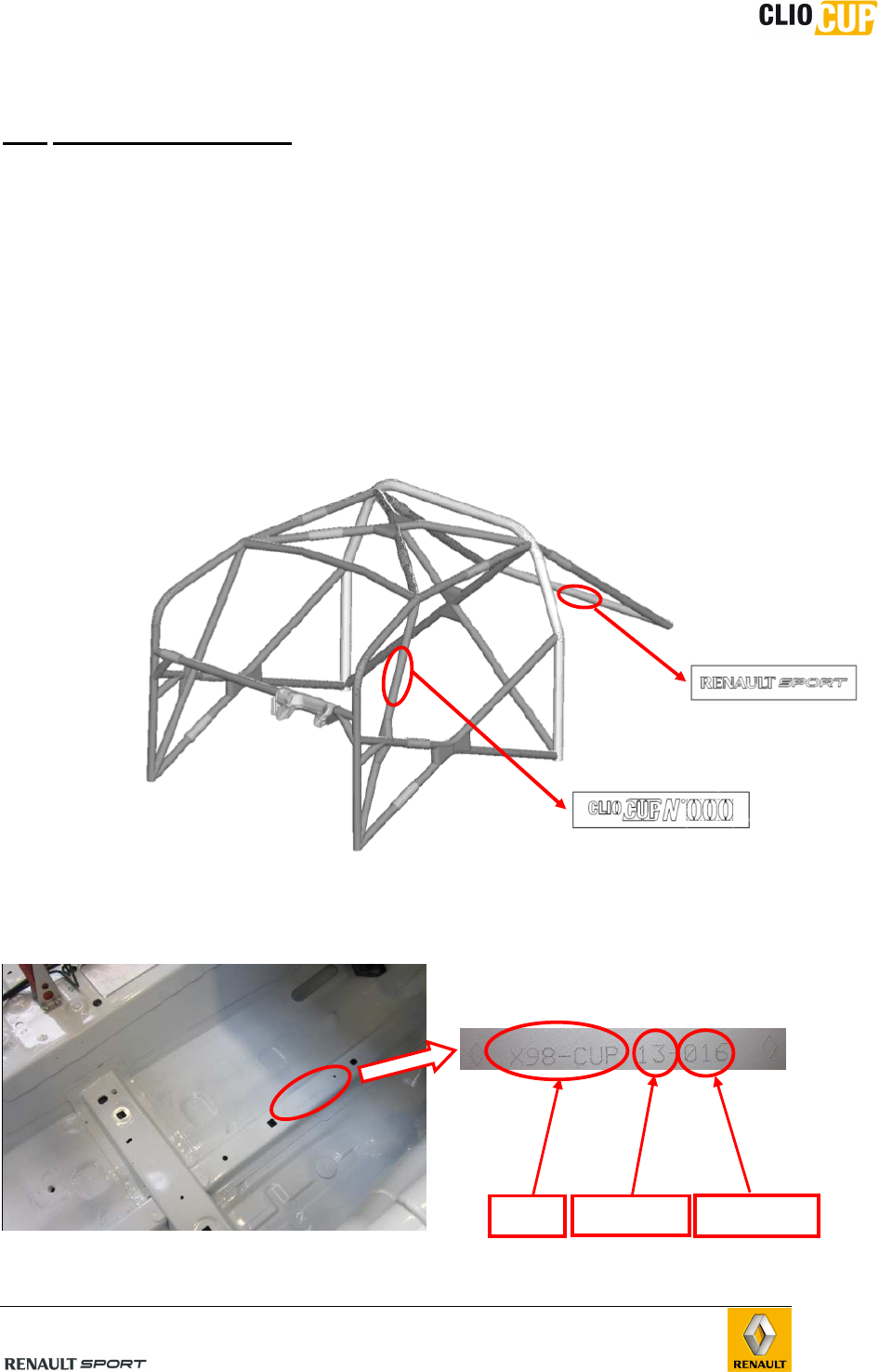
B.1.1 ROLL CAGE
The roll cage is directly welded to the chassis
The roll cage plate is located on the left windscreen reinforcement tube
It features the following information:
_ Model : CLIO CUP
_ Serial number : xxx
The manufacturer plate “RENAULT SPORT” is located on the rear transversal tube
The roll cage is homologated by the Automobile Sport French Federation :
FFSA (Federation Française du Sport Automobile)
B.1.2 CHASSIS NUMBER
The chassis number is engraved on the passenger side of the centre crossmember.
Type
Year
Serial N°
98CUP_2013 Release
C-5
NOTE : The chassis number must correspond to the roll cage number. These 2 parts are
indissociable. It is strictly forbidden to change them separately.
The non respect of this rule is a technical non conformity
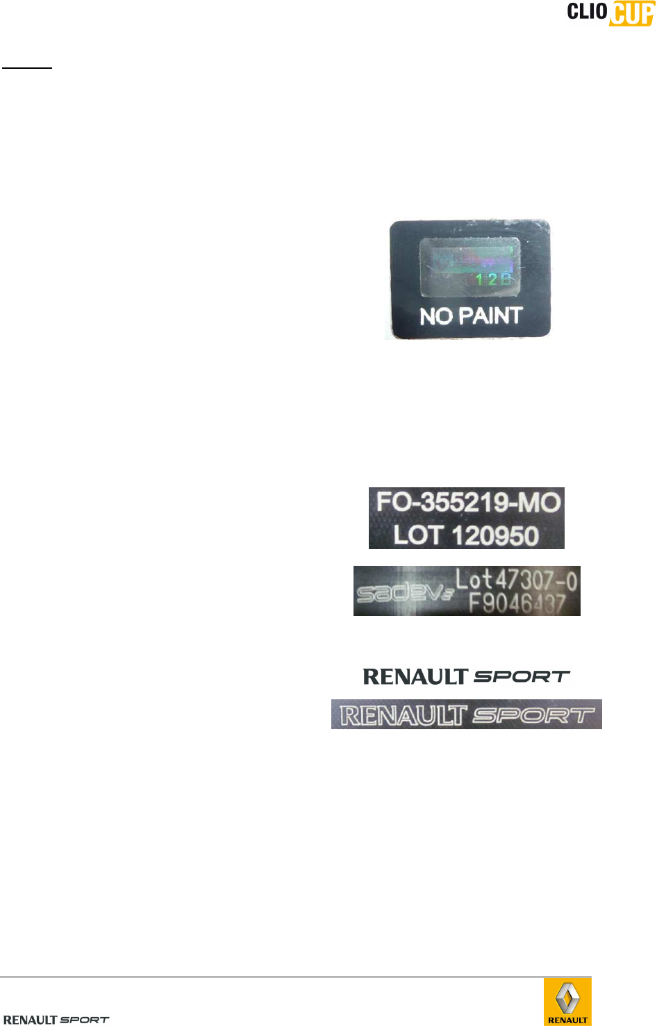
B.1.3 HOLOGRAMS
The bodywork parts and certain mechanical
components are identified using embossed
hologram disks (see Appendix/List of
marked parts).
The wording “NO PAINT ” indicates you
must not paint over the hologram under any
circumstances.
The presence of the holograms is
mandatory. The absence of hologram(s)
may be regarded as technical non-
compliance and event organizers may
require that the part(s) in question be
replaced.
B.1.4 MARKINGS
Certain mechanical components are
identified using an engraving (see
Appendix/List of marked parts).
An engraving is proof that the part is
genuine, but does not confirm that it
complies with regulations.
The absence of engraving(s) may be
regarded as technical non-compliance and
event organizers may require that the
part(s) in question be replaced.
Supplier engraving examples :
Renault Sport engraving :
98CUP_2013 Release
C-6
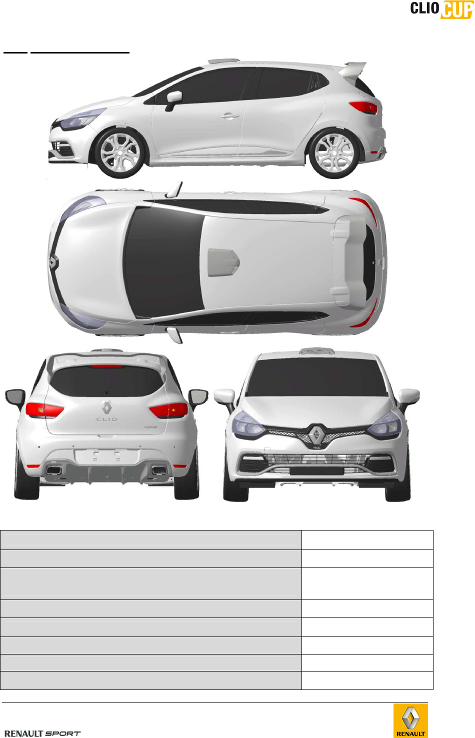
B.2 DIMENSIONS
Overall length (mm) 4090
Overall height on roof hatch (mm) 1429
Overall width (mm)
(Rearview mirror - front and rear mudguard) 1945 - 1732 - 1726
Wheel base (mm) 2576
Front track (at axle) – middle of the tyre (mm) 1550
Rear track (at axle) – middle of the tyre (mm) 1520
Total weight (without fuel) (kg) 1065
Front/rear split [%] 63/37
98CUP_2013 Release
C-7
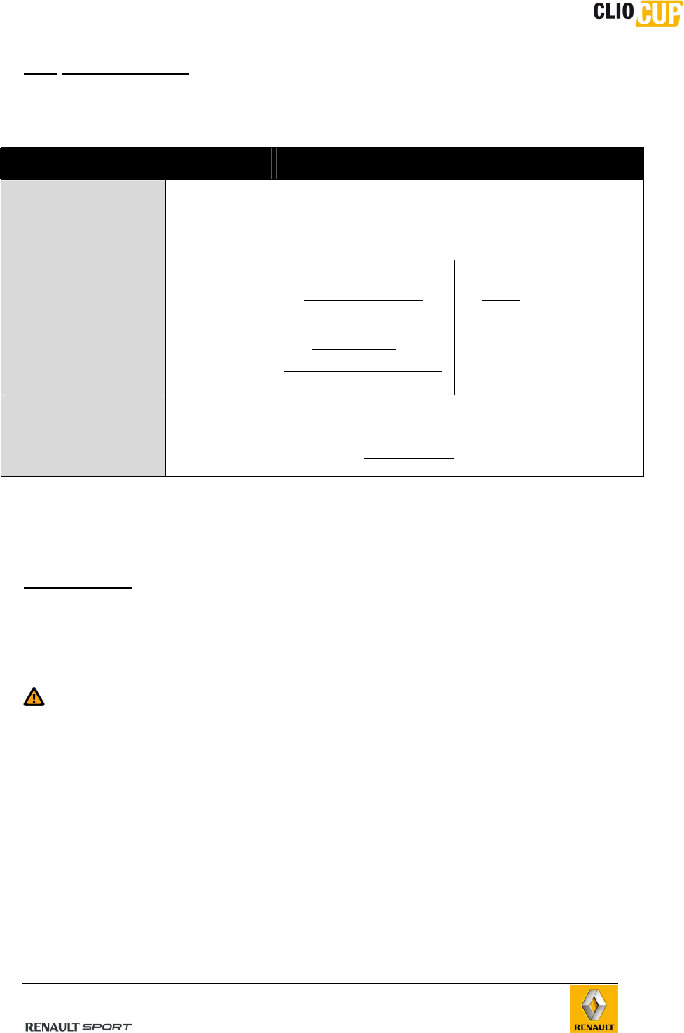
B.3 CAPACITIES
REGULATIONS / RECOMMENDATIONS
Capacity Characteristics Comments
Fuel tank 42L
• Free practice or private testing: SP 98
grade unleaded
• Events: see technical regulations
Tolerance:
-0L/+1.5L
Engine lubricant
4.0L : engine
(4.2L with the
oil filter)
Elf EXCELLIUM NF 5W40 See technical
regulations
Gearbox lubricant
Casing : 1.3L
(1.5L with the
cooling circuit)
ELF HTX 755 or
Motul Gear Competition
(SADEV preconisation )
80 W 140
75W140
See technical
regulations
Coolant 6.5L Glaceol RX Type D free
Front/rear brake
fluid <800mL CASTROL SRF See technical
regulations
The use of :
• Elf Excelcium 5W40 engine oil
• CASTROL SRF brake fluid
are mandatory (refer to technical regulations).
You are free to use alternatives for all other fluids, but they must comply with the
characteristics specified above.
All brand new cars are delivered with
TOTAL SP98 grade unleaded : 10L
Elf Excellium NF 5w40 engine oil
CASTROL SRF brake fluid
ELF HTX 755 gearbox oil
98CUP_2013 Release
C-8
B.4 GENERAL CHARACTERISTICS
Description Dimensions
SCx 0.869
Front SCz 0.024
Rear SCz -0.08
Total SCz 0.016
Recommanded dry setup : See Chapter E- CHASSIS
Front ground clearance at standstill (MICHELIN tyre) 120mm
Rear ground clearance at standstill (MICHELIN tyre) 220mm
Front camber at standstill (deg . min) -3°30’
Rear camber at standstill (deg . min) -2°0’
Tyre radius under load (400kg)
MICHELIN S9D : 200kph / 0°camber / inflate press 1.9b
DUNLOP A46D : 200kph / 1° camber/ inflate press 2.1b
291mm
305mm
Vertical stiffness of front/rear tyre
MICHELIN S9D
DUNLOP A46D
320 N/mm
290 N/mm
Front/rear tyre dimension
MICHELIN S9D
DUNLOP A46D
20/61-17
21/62-17
Front/rear wheel dimensions 8’’ x 17’’
Front unsprung mass per ¼ of vehicle 53kg
Rear unsprung mass per ¼ of vehicle 40.5kg
Front sprung mass per ¼ of vehicle
(1160kg : total race weight) 370kg
Rear sprung mass per ¼ of vehicle
(1160kg : total race weight) 210kg
Engine power 162kW (220bhp) [6,000rpm]
Max. engine speed 6,500rpm
Max. engine torque 270N.m (27.5m.kg)
[2,500 to 5,500rpm]
Front camber variation
Variation in front roll centre
Front wheel alignment variation at compression
Front wheel alignment variation at rebound
See section E-CHASSIS
Front shock absorber / wheel installation kinematics ratio 1.03
Rear camber variation
Variation in rear roll centre
Rear wheel alignment variation at compression
Rear wheel alignment variation at rebound
See section E-CHASSIS
Rear shock absorber / wheel installation kinematics ratio 1.04
98CUP_2013 Release
C-9
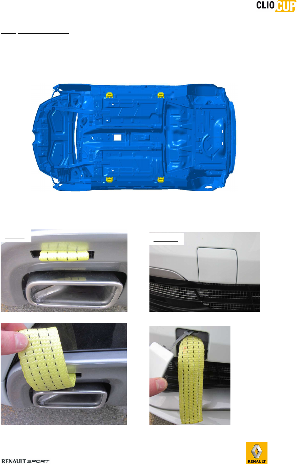
B.5 HANDLING
B.5.1 LIFTING
The vehicle has to be raised at the front and rear using a jack.
The jack must be positioned beneath the pad provided (in Yellow on the following
picture)
B.5.2 TOWING
The vehicle may be towed from the front or the rear using the strap provided :
When not used, the strap is tucked in the bumper When not used, the strap is completely tucked
CAUTION : minimimum 1cm must be outside to pull it in the front bumper behind the genuine cover.
REAR
FRONT
98CUP_2013 Release
C-10
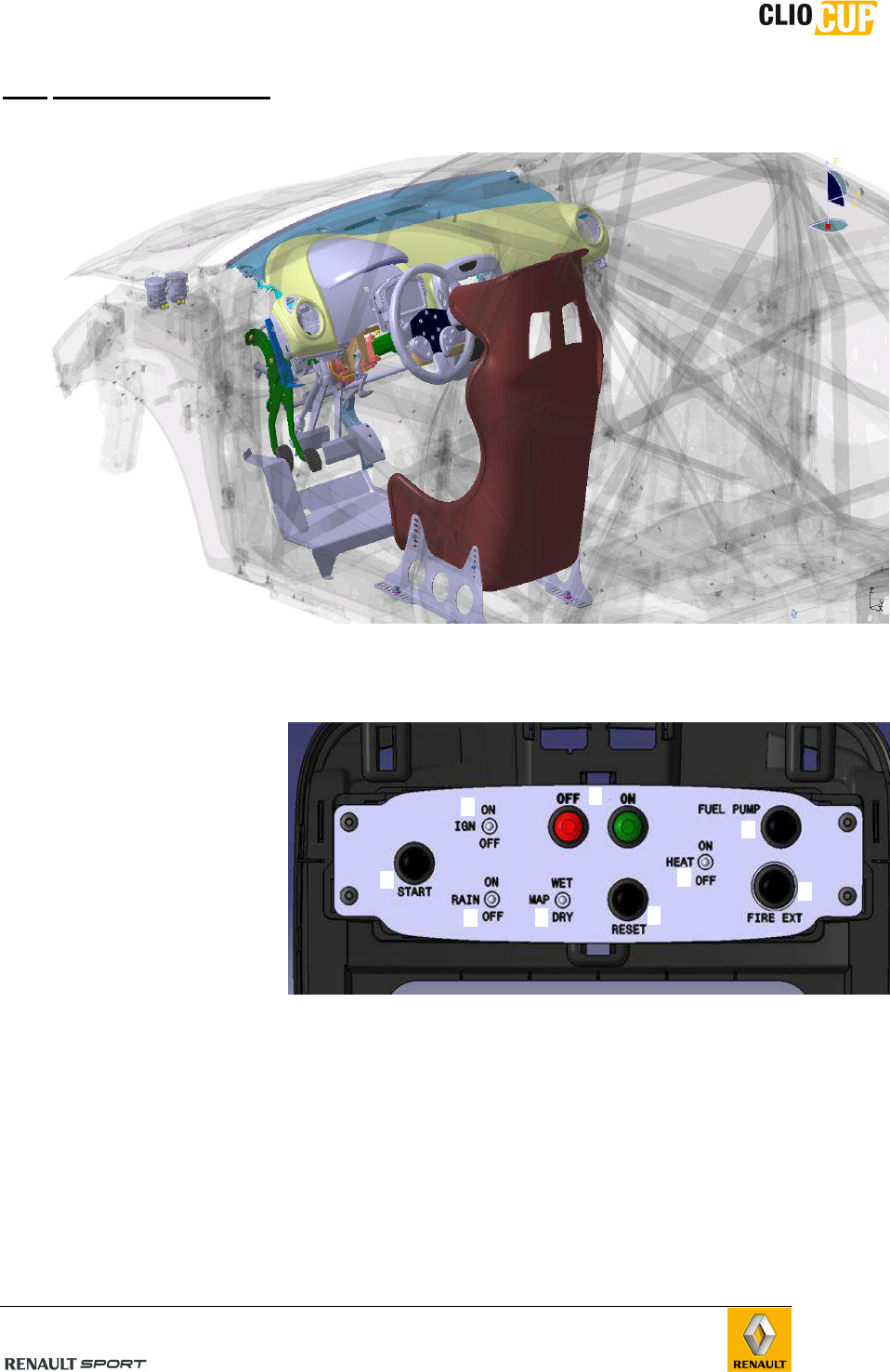
B.6 USING THE CAR
B.6.1 FACIA SWITCH PANEL : XAP_SWT98
1 – Power supply
2 push buttons ON/OFF
2 – Ignition
1 switch ON/OFF
3 – Starter excitation
1 push button
4 – Fuel pump override
1 push button
5 – Rear Rain light
1 switch ON/OFF
6 – Engine Map
1 switch DRY/WET
7 – Reset :
1 push button
8 – Heating :
1 switch ON/OFF
9 – Fire extinguisher
1 push button
1
2
4
3
5
6
7
8
9
98CUP_2013 Release
C-11
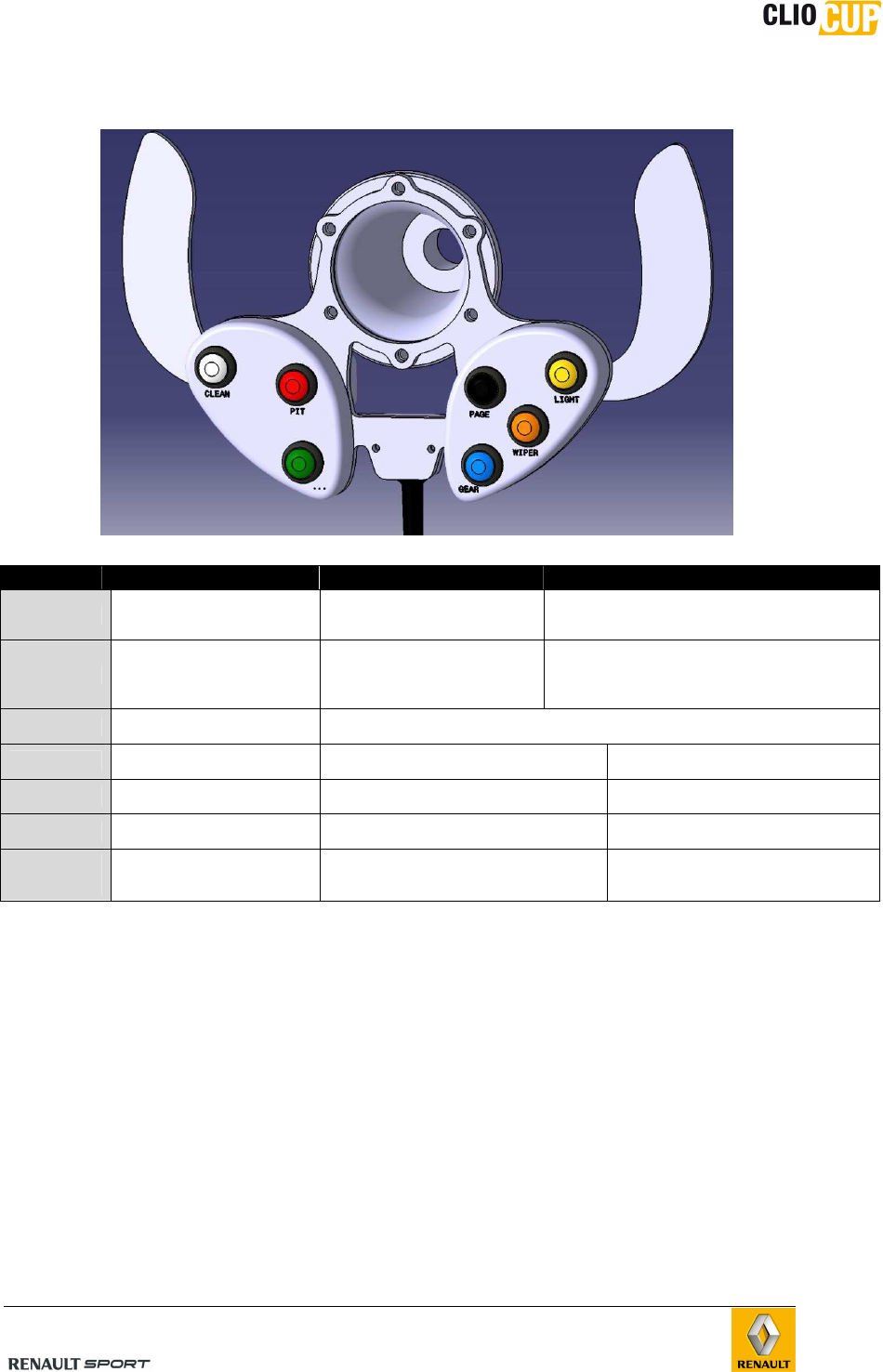
B.6.2 STEERING WHEEL SWITCH PANEL : XAP_STER98
Button Action Short press Long press
LIGHT Light management
(Front headlight and rear) Head light flasher 1st Long press : light goes ON
2nd long press : light goes OFF
WIPER Wiper management 1 go/back wiper, return to
“0” position
1st Long press : permanent wiper on only
one constant speed (maximum speed)
2nd long press : wiper stops and returns
at “0” position
CLEAN Windscreen cleaning
(wiper + pump)
While this push button is pressed, wiper and windscreen washer work
together. When released, wiper return to “0” position
PAGE Access to the dashboard
pages Change page Switch between “diagnostic pages”
(3) and “driver pages” (5)
PIT Pit limiter management 1st short press : enable (60kph)
2nd short press : Disable /
GEAR Gearbox barrel unlocking
(safety)
Unlock the gearbox barrel (see
chapter D “Trasnmission-sifting”) /
GREEN
BUTTON Free button
Management accessible using the
free connector on chassis loom (See
chapter F “wiring looms”)
/
98CUP_2013 Release
C-12
B.6.3 DASHBOARD: COSWORTH ICD 01D-032954-RST
B.6.3.1 Pages
The display contains 8 pages classified in 2 different families :
- Family 1 : 3 “driver” pages
- Family 2 : 5 “diagnostic” pages
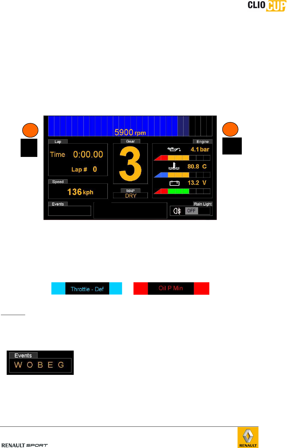
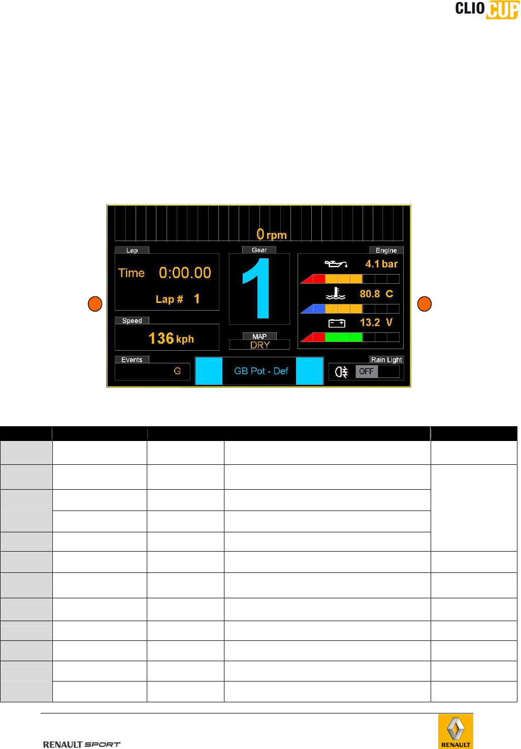
B.6.3.1.1 DRIVER PAGE 1 : RACE PAGE
Area “LAP” :
Time : Current lap time (stay displayed 10s after having being cut)
Lap # : number of lap completed during the RUN
Area “Speed” :
Current speed displayed (depends on tyre diameter, configurable in Toolset (see
chapter G - Softwares)
Area “Default” :
When 1 or several defaults appear, they are scrolling on this area when the default is still
present.
NOTE : Even if the defaults disappears (Oil_P min, or GB_pot_def for example) :
- A letter in the area “Event” is recorded depending on the kind of default.
- A alarm LED appears on top right or top left position (engine or Gearbox alarm)
Area “Event:
Each letter means that during the last or current RUN, an
alarm was recorded (even if it disappeared after) to
encourage team to check the default.
W : Water temp alarm recorded (min or max)
O : Oil pressure recorded (min or max)
B : Battery voltage recorded (min or max)
E : engine alarm recorded (other engine sensor than W, O, B)
G : gearbox alarm recorded
Default
Engine
alarm
LED
Gearbox
alarm
LED
98CUP_2013 Release
C-13
Area “MAP”
“DRY” or “WET” depending on the engine MAP selected on the Facia switch panel
Area “GEAR”
Corresponds to Gearbox ratio engaged (R, N, 1, 2, 3, 4, 5, 6)
Area “RPM”
Current engine speed in RPM (“xxxx RPM”)
Area “RAIN LIGHT”
“OFF” (grey background) or “ON” (green backgound) depending on the Facia switch
panel interrupter position.
Area “Engine”
Engine oil pressure (bars)
Engine water temperature (°C)
Battery voltage (V)
NOTE : these 3 Values corresponds to the Category A alarms
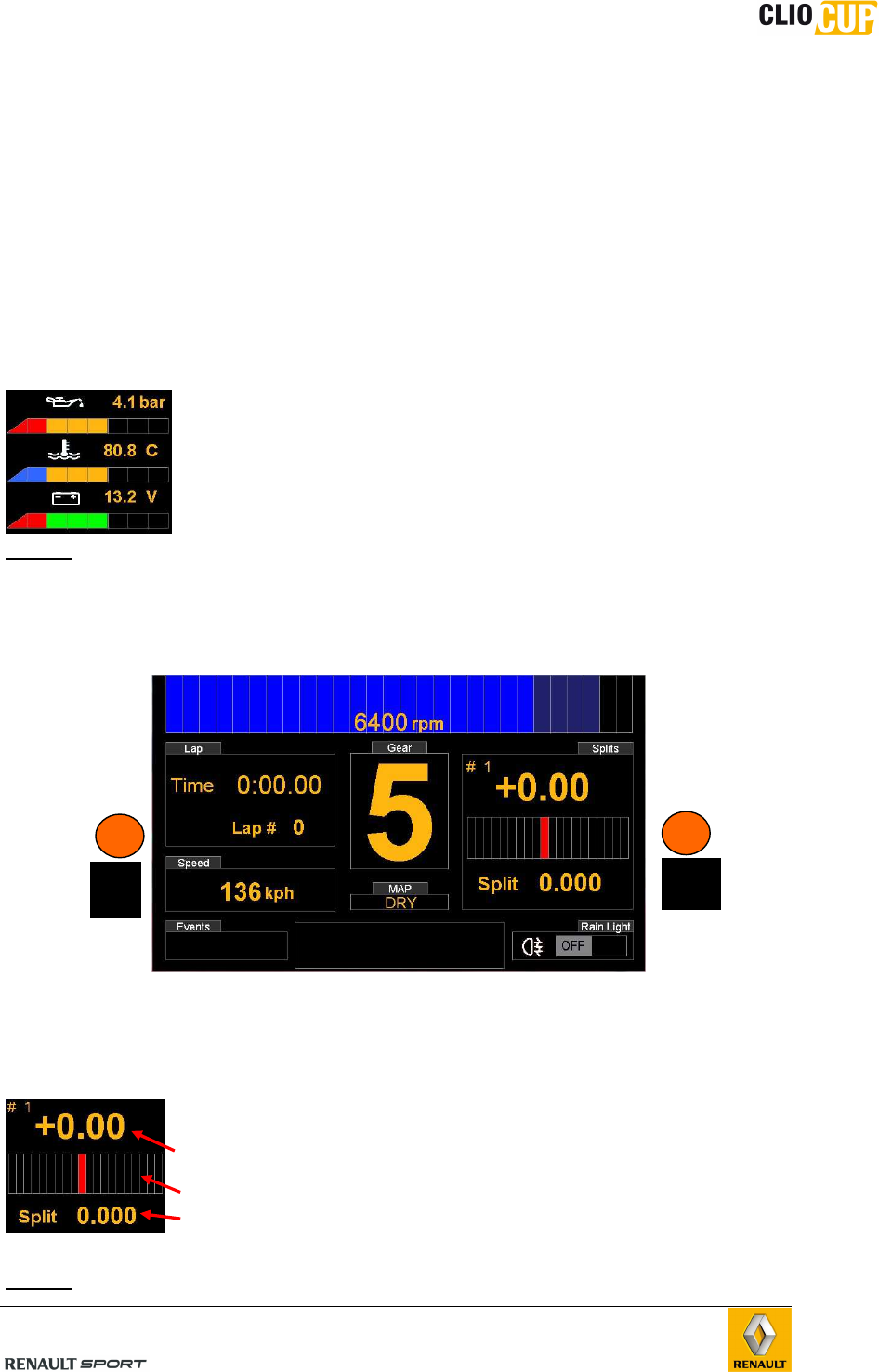
B.6.3.1.2 DRIVER PAGE 2 : QUALIFICATION PAGE
Area “LAP”, “Speed”, “MAP”, “Events”, “Default”, “rain light”, “RPM”, “GEAR” and “alarms
LED” remains the same as the RACE PAGE. Only the “Splits” replace the “engine” area
Area “Splits”
This Area represents the Qualifying mode (QM) configuration
- Time difference : current split compared to split recorded from
the best lap
- Bargraph : 1 bar = 1 tenth (+/- 1 sec)
- Split : Current split time : reference
NOTE : Refer to chapter G-Softwares for the full Qualifying mode configuration
Default
Engine
alarm
LED
Gearbox
alarm
LED
98CUP_2013 Release
C-14
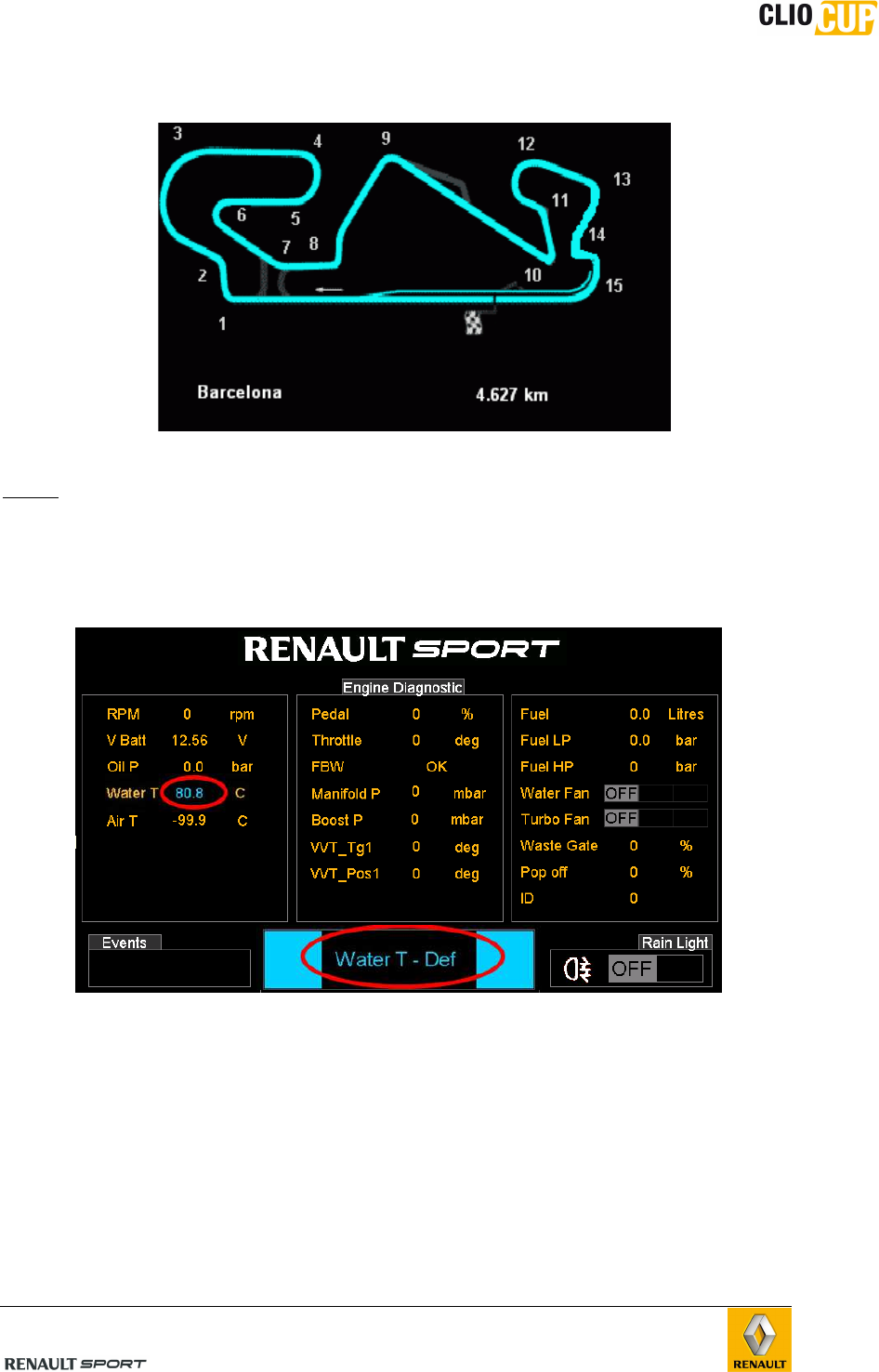
B.6.3.1.3 DRIVER PAGE 3 : CIRCUIT MAP PAGE
Refer to chapter G-Softwares to upload a circuit map (.bmp)
NOTE: This map is just for information and is not dynamic
B.6.3.1.4 DIAGNOTIC PAGE 1 : ENGINE DIAGNOSTIC
Areas “Events”, “Default” and “rain light”, remains the same as DRIVERS PAGE.
NOTE:
When an alarm appears in the area “default”, the corresponding value by default is
displayed in blue, red or orange.
98CUP_2013 Release
C-15
Engine diagnostic parameters : (see also chapter C-Engine)
Engine
parameters
Signification
Values expected
when engine is
OFF
Values expected when Engine is
running
RPM Engine revs 0
- Idle > 1200rpm
- WaterT<50°c : RPM limiter = 4500rpm
- 50°c<Water T<100°C, RPM limiter = 6500rpm
- WaterT > 100°c, rpm limiter decrease
progressively to reach 3500rpm at 120°c
VBatt (V) Battery voltage 11.5V to 12.5V > 13.5V
OilP (b) Oil pressure 0 >1.5b when engine RPM>3000
WaterT (°C) Water temp #ambient temp when the
car is cold
Water temp progressively increase to 87°c
(Water fan goes ON at low speed)
AirT (°C) Air intake temp #ambient temp when the
car is cold
Air temp progressively increase when the car is
in static position
Pedal (%)
Gas Pedal
potentiometer
position
0 > 100% depending on
Gas pedal position 0 > 100% depending on Gas pedal position
Throttle (°)
Throttle
potentiometer
position
<9°
(depends on water temp) 0> 100° depending on Gas pedal position
FBW Fly by wire status OK OK
Manifold P Manifold air pressure Atmospheric pressure
- Idle : Manifold P< 350mb
- When Water T >55°c Manifold P follows strictly
the BoostP (at 100% throttle)
Boost P Boost pressure Atmospheric pressure
- Boost P < 1.1b when Water T <30°c
- When 30°c < Water T < 50°c => BoostP
increase progressively
- when water T > 50°c => BoostP can go to its
maximum value (2.1b)
VVT1_tg (°)
VVT1 target =
instruction sent by
ECU to the dephaser
0 If WaterT < 55°, VVT1_tg =0
As soon as WaterT>55°, VVT1_tg=100
VVT1_pos (°)
Intake
camshaft pos :
depends on VVT1_tg
0
- After starting : automatic calibration (10sec)
- Then VVT1_pos = 100°
- when water T>55°, VVT1_pos must strictly
follows VVT1_tg
Fuel (L) Fuel level Fuel Level Fuel level
Fuel LP (b)
Fuel press
(measured at the
exit of the fuel cell)
0b / 5b maxi when “fuel
pump” button is pressed 4.7<fuel LP<5.0b
Fuel HP (b) Fuel press (HP rail) <10b
- 18b < fuel HP <180b
-If fuel HP < 15b during starter excitation, the
engine will not start, it’s necessary to bleed the
air inside of the rail
(see procedure in chapter C-Engine)
Water Fan Water fan speed OFF
(depends on water temp)
LOW (Low speed) when Water T >87°C
OFF when Water T <86°C
HIGH (High speed) when Water T >90°C
LOW when WaterT <88°C
See chapter C-Engine
Turbo Fan Turbo fan OFF
(depends on Air temp)
ON if Air temp is > 50°C
OFF when Air temp is <48°C
Waste Gate
(%) Waste gate duty 0 Depends on Boost pressure target
Must always be under 70%
Pop off (%) Pop off valve pos 0 (close)
- 100% (open) after an complete closure of the
throttle and Boost P > 1400 mbar (to reduce the
pressure upstream to the closed throttle)
- 100% if WaterT <50°c
ID Not used
For reliability reasons and to avoid alarms risings, it’s strongly
recommended to let the engine warm up to a water temp > 60°C
before any practising. If this condition is not respected, the full engine
power won’t be available.
98CUP_2013 Release
C-16
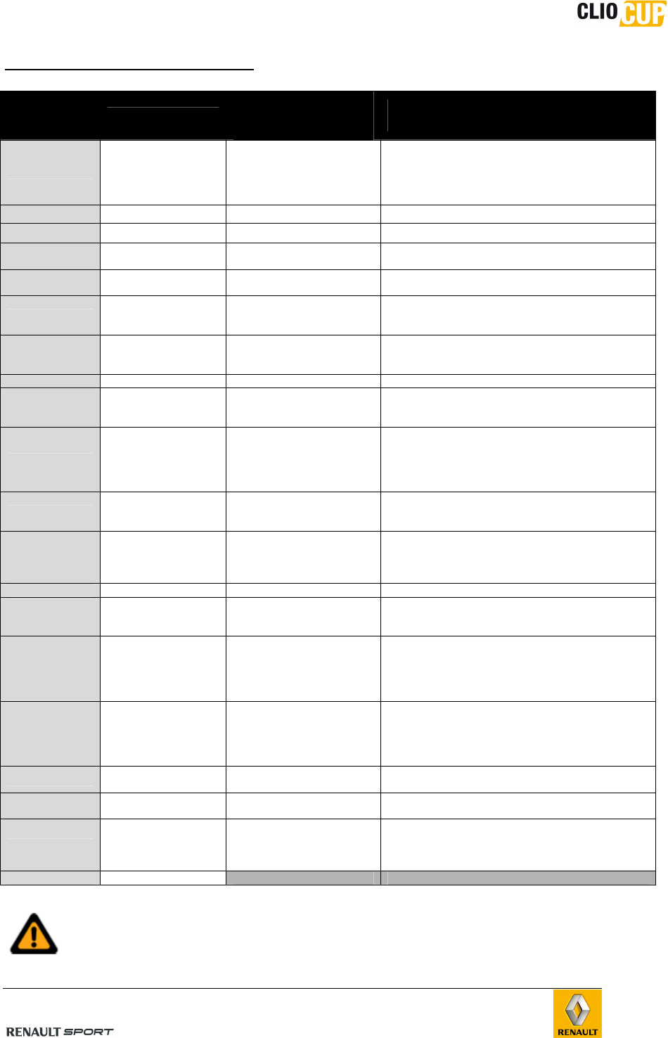
B.6.3.1.5 DIAGNOSTIC PAGE 2 : GEARBOX DIAGNOSTIC
(see also chapter D-Transmissions)
Areas “Events”, “Default” and “rain light”, remains the same as DRIVERS PAGE.
Gearbox
parameters
Signification
Values expected
when engine is
OFF
Values expected when Engine is
running
RPM Engine revs 0
- Idle > 1200rpm
- WaterT<50°c : RPM limiter = 4500rpm
- 50°c<Water T<100°C, RPM limiter =
6500rpm
- WaterT > 100°c, <rpm limiter = 3500rpm
VBatt (V) Battery voltage 11.5V to 12.5V > 13.5V
Barrel (V)
Gearbox barrel
potentiometer
voltage
1st gear :
1.60 V+/-10mv
+0.5v / gear in upshift phase
-0.5V / gear in downshift phase
Gear Gear ratio
engaged R N 1 2 3 4 5 6 R N 1 2 3 4 5 6
Up SW UPshift paddle ON : paddle pressed
OFF : rest
ON : paddle pressed
OFF : rest
Down SW DOWNshift
paddle
ON : paddle pressed
OFF : rest
ON : paddle pressed
OFF : rest
Gear SW
Gearbox barrel
unlocking
solenoid.
ON : “GEAR” button
pressed
OFF : rest
ON : “GEAR” button pressed
OFF : rest
Up Cont Upshift contactor
OFF : during downshift
and at rest
ON : during upshift
OFF : during downshift and at rest
ON : during upshift
FL WSP (kph) Front left wheel
speed 0 >0 when a gear is engaged
FR WSP (kph) Front right wheel
speed 0 >0 when a gear is engaged
NOTE 1:
The complete gearbox strategies (manual mode or semi-auto mode) is described in
Chapter D-transmission/shifting
NOTE 2 :
When an alarm appears in the area “default”, the corresponding value by default is
displayed in blue, red or orange.
98CUP_2013 Release
C-17
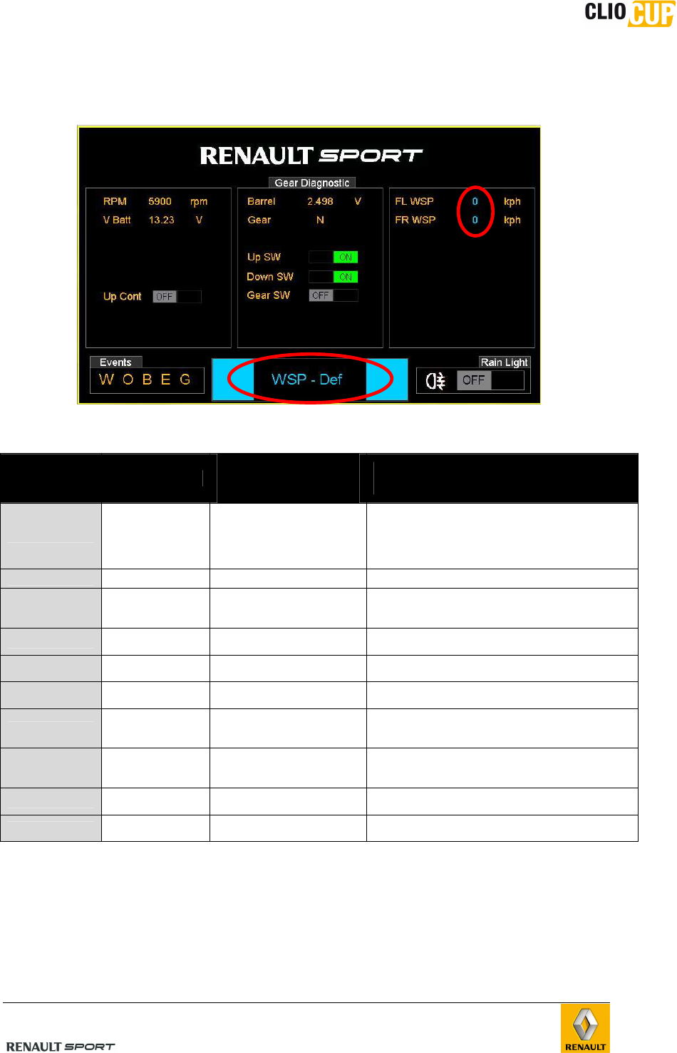
B.6.3.1.6 DIAGNOSTIC PAGE 3 : BRAKE / CHASSIS DIAGNOSTIC
Brake/
chassis
parameters
Signification
Values expected
when engine is
OFF
Values expected when Engine is
running
Front BP Font brake pressure From 0 to more than 100b
Rear BP Rear Brake pressure From 0 to 40b (depends on rear brake pressure limiter setup)
Balance % of brake pressure
on front axle From 40% to 70% (depends on balance bar rod setup)
Steering Steering angle
sensor -360° to + 360°
FL WSP (kph) Front left wheel
speed 0 >0 when a gear is engaged
FR WSP (kph) Front right wheel
speed 0 >0 when a gear is engaged
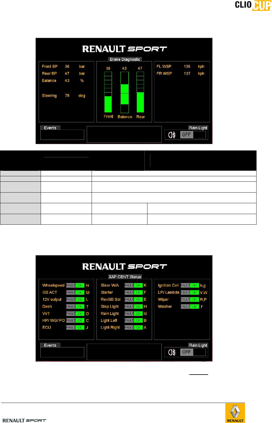
B.6.3.1.7 DIAGNOSTIC PAGE 4 : CBNT DIAGNOSTIC (PAGE 1/2 : STATUS)
Every indication corresponds to the XAP CBNT pinout and shows the status (OK / FAULT)
of each Pin (one Letter = A, B, h, g…etc = 1 Pin). All values must be “OK” (green).
When “FAULT” appears, the Pin is not correctly supplied. Please refer to chapter F- wiring
for more details.
98CUP_2013 Release
C-18
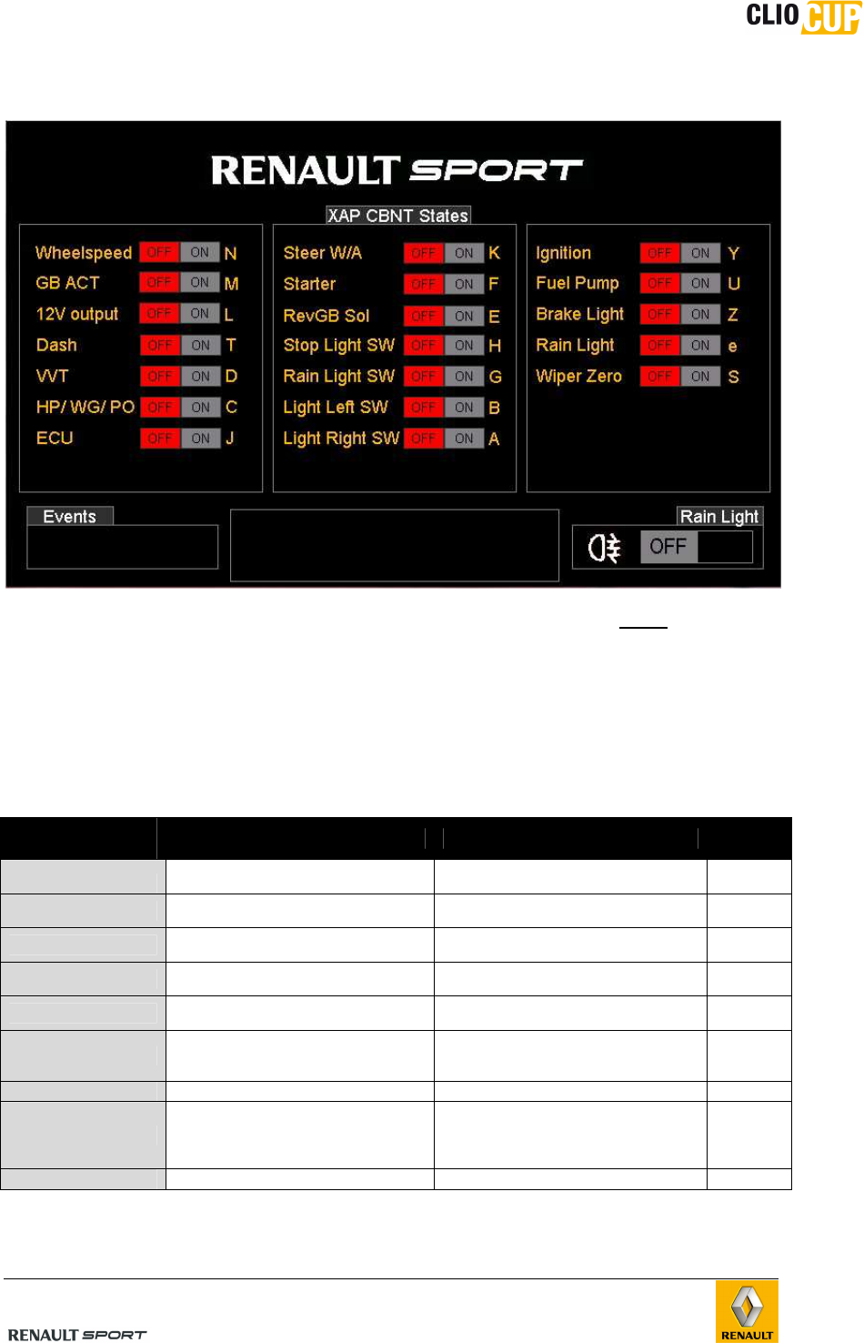
B.6.3.1.8 DIAGNOSTIC PAGE 5 : CBNT DIAGNOSTIC (PAGE 1/2 : STATES)
Every indication corresponds to the XAP CBNT pinout and shows the state (ON/OFF) of
each Pin. Please refer to chapter F- wiring for more details.
When XAP Master relay is ON :
- All values from the first column must be “ON” (green)
- On the second column, Steer W/A, starter and revGB Sol must be “ON” green, for the
other Pins, please find the action/result below :
Sensors
/actuators Signification Action result
stop light SW Brake Pedal
contactor switch Brake pedal pressed OFF >ON
rain light SW Rain light switch on facia switch
panel “Rain ” switch ON OFF >ON
light left SW Left side lights switch on steering
wheel “light” button pressed OFF >ON
light right SW Right side lights switch on steering
wheel “light” button pressed OFF >ON
ignition Ignition coils switch on facia switch
panel “ignition” switch ON OFF >ON
fuel pump Fuel tower pump (facia switch panel
manual mode or automatic mode)
state
“fuel pump” button pressed and/or
automatic fuel pump management OFF >ON
brake light Lateral rear brake light state Brake pedal pressed OFF >ON
rain light** Rear central rain light state
Brake pedal pressed
And/or « Rain » switch ON
And/or pit limiter ON
And/or Reverse gear ratio engaged
OFF >ON
wiper zero “Wiper” position state When “wiper” leave its rest position ON>OFF
** Please refer to Central rear rain light activation strategies in this chapter
98CUP_2013 Release
C-19
B.6.3.2 Changing pages
The pages of the display may be changed by pressing on the push button ‘PAGE” of the
steering wheel
- Pressing briefly on this button (one second) moves the display in the 3 driver
pages
- Pressing this button for longer (more than 2 seconds) moves the display from
driver pages to diagnostic pages
- Pressing briefly on the button moves the display in the 5 diagnostic pages
You can return to the driver pages by pressing the button for a longer period (more than
2 seconds). The display returns to the first driver page
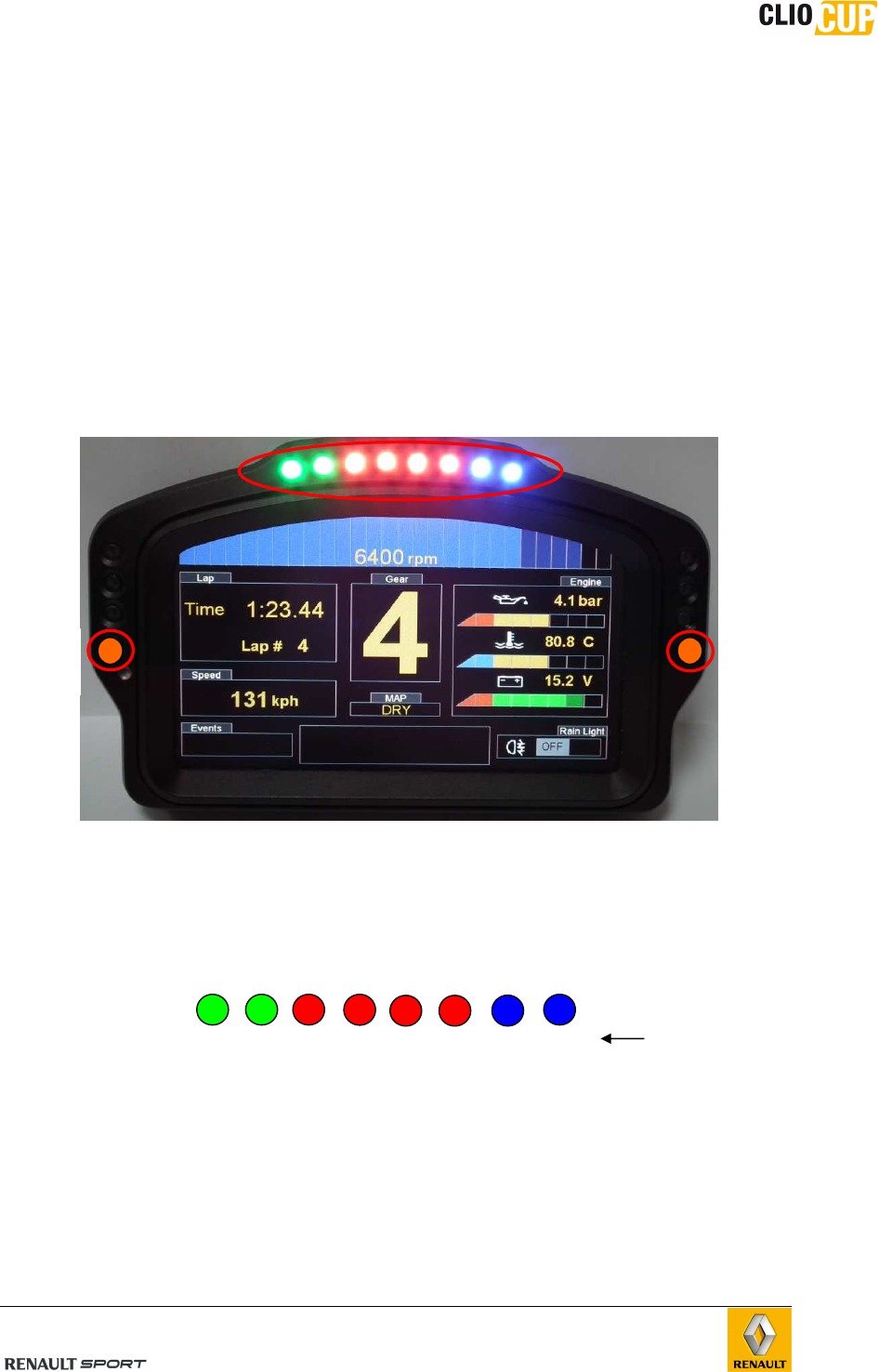
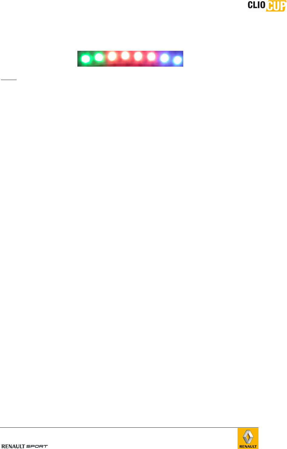
B.6.3.3 Leds / shiftlights
Shiftlights (8):
Shiftlight thresholds are fully configurable using the “Toolset” software, see chapter G-
Softwares
The LEDs light up in all gear ratios. By default, the setup is the following one:
LEDs Alarm (2):
On the left side, 1 LED lights up when an engine alarm rises up
On the right side, 1 LED lights up when a Gearbox alarm rises up
These LEDs are associated with the message displayed in the area “Default” and with the
letter recorded in the area “events”
Engine
alarm
LED
gearbox
alarm
LED
Shiftlights
5000
5200
5400 5600
5800
6000
6200 6300
Engine RPM at which LEDs
light up
98CUP_2013 Release
C-20
B.6.3.4 Alarms displayed on the dashboard
Alarms are generated by the ICD depending on engine / gearbox sensors values sent by
the ECU for display.
The alarm/default message disappears only when the problem is solved. Even if the
problem is solved, till the power supply is ON :
- The top left and/or right LEds alarms remain ON
- The letter in the area “event” is displayed
We distinguish 2 categories of alarms : A and B
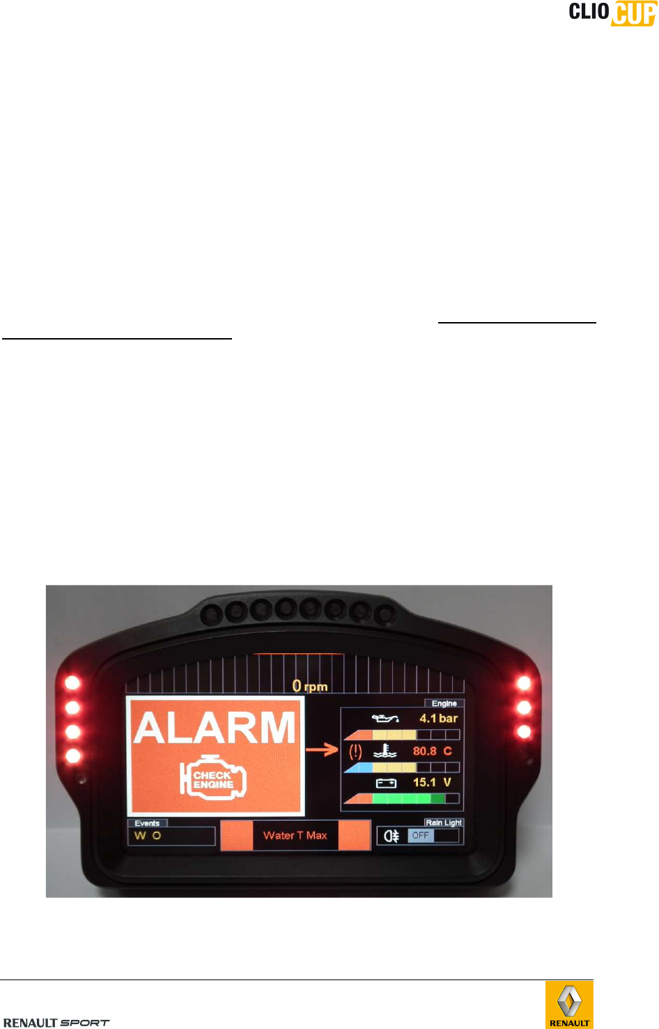
B.6.3.4.1 MAIN ALARMS (CATEGORY A)
The following alarms are displayed to the driver, meaning that he must immediately
stop the car and cut the engine.
o Water T max
o Oil P min
o Vbatt min
See List on next page with the corresponding thresholds.
A message is displayed on the full screen on the dashboard + in the Area ‘Default” to
force the driver to stop
In addition with the message displayed, all the following LEDs become RED:
- 3 on the Right column (above gearbox diagnostic LED)
- 3 on the Left column (above engine diagnostic LED)
+ 1 engine alarm LED in RED
98CUP_2013 Release
C-21
B.6.3.4.2 SECONDARY ALARMS (CATEGORY B)
All non Cat A alarms are classified in the category B. They are clearly displayed to the
driver, but he is still able to drive normally (the dashboard information remains normally
readable).
A message is displayed in the Area “Default”
In addition with the message displayed, the corresponding alarm LED becomes ORANGE:
- 1 Right HS column (gearbox diagnostic)
- 1 Left HS column (engine diagnostic)
If 1 or more alarms are present, the messages are scrolling in the “default” area
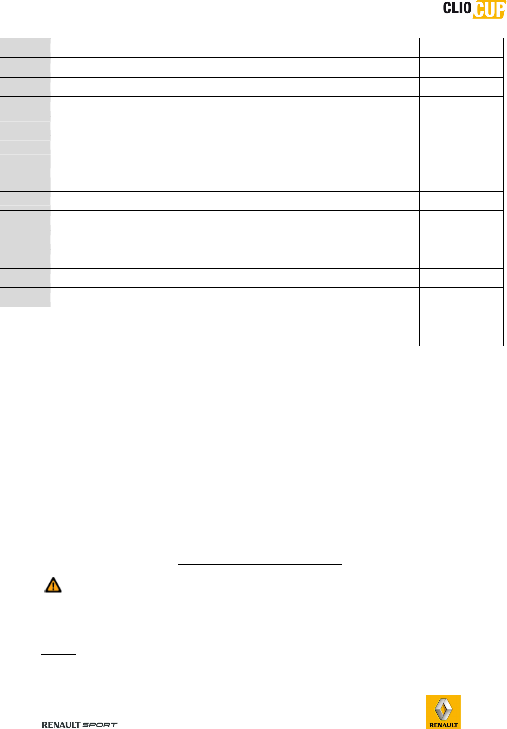
B.6.3.4.3 ALARMS AND THRESHOLD
Category Message Alarm LED Meaning Threshold
A “V BAT MIN”
+ value in Red 4 LEFT + 3 RIGHT
Min. battery voltage V batt < 11V and
revs > 4000 rpm
B “V BAT MAX”
+ value in Orange 1 Left Max. battery voltage V batt > 15V
B “OILP max”
+ value in Orange 1 Left Max. oil pressure Oil P > 6 bar
A “OILP min”
+ value in Red 4 LEFT + 3 RIGHT
Min. oil pressure Oil P < 1.5 bar and
revs > 3000rpm
A “Water T Max”
+ value in Red 4 LEFT + 3 RIGHT
Max. water temperature > 105°C and
revs > 1000 rpm
B “Water T Min”
+ value in Orange 1 Left Min. water temperature <40°C and
revs > 4000rpm
B "AIR T MAX"
+ value in Orange 1 Left Max. air temperature Air T > 90°C
revs > 1000 rpm
B “HP fuel min”
+ value in Orange 1 Left Min HP fuel pump (rail pressure) < 300 mbars and
revs > 1500 rpm
B “LP fuel min”
+ value in Red 1 Left Min LP fuel pump < 3 bars and
revs<1000rpm
B "Throttle - def"
+ value in Blue 1 Left Electrical fault on electrical throttle pot. -
B “Pedal - def”
+ value in Blue 1 Left Electrical fault on pedal pot -
B "Boost P/ air T - def"
+ value in Blue 1 Left Electrical fault on boost pressure / air Temp sensor
-
Engine
alarm
LED
gearbox
alarm
LED
98CUP_2013 Release
C-22
B " Manifold P - def"
+ value in Blue 1 Left Electrical fault on manifold sensor -
B "Oil P - def"
+ value in Blue
1 Left Electrical fault on oil pressure sensor -
B "Water T - def"
+ value in Blue
1 Left Electrical fault on water temperature sensor -
B “Throt FBW * def”
+ value in blue
1 Left Electrical fault on motorised throttle
B “High press def”
+ value in Blue
1 Left High pressure sensor default -
B “Low press def”
+ value in Blue
1 Left Low pressure sensor default -
B " V.V.T.1 - def"
+ value in Blue 1 Left Intake V.V.T. servo control default
difference > 10°
between
VVT1_tg and
VVT1_pos during
more than 5s
B “GB actuator - def”
+ value in Blue 1 Right Gearbox actuator default (only if connected) -
B "GB Pot - def"
+ value in Blue 1 Right Electrical default on barrel position sensor -
B “up contact – def”
+ value in Blue 1 Right Electrical default on upshift contactor -
B “Solenoid R”
+ value in Blue 1 Right Electrical default on reverse solenoid (barrel
unlocking) -
B "CBNT - Can Def" - CAN CBNT fault -
B "Steering - def" - Major/minor fault on power steering module -
“Gear” - Gear button pressed, message displayed in the
middle of the screen without alarm
"Pit Limiter" - Speed limiter enabled, message displayed
on the top
of the screen without alarm -
B.6.4 BASIC PROCEDURES
B.6.4.1 Power-up
Press the “ON” button of the facia switch panel (See B.6.1) to power supply the vehicle
The “COSWORTH” home page appears when the dashboard display first comes on, and
then moves to the first driver page (RACE Page)
B.6.4.2 Starting
Once the vehicle’s electrics are on, flick the vehicle's “IGNITION” switch to the up (ON)
position.
Check that no gear is engaged (the letter “N” is displayed on one of the display screen’s
driver pages).
Press on the “START” button without touching the Gas Pedal
The vehicle will only start if the following electronic equipments are connected
and are working properly:
- ECU
- CBNT
- Master relay
It is possible to start without plugging the dashboard
NOTE : For the first engine start after engine refitting, it’s necessary to bleed the fuel
rail. To make it properly, please follow carefully the procedure indicated in chapter C-
Engine
98CUP_2013 Release
C-23
B.6.4.3 Turning off the engine
Flick the “IGNITION” switch to the down (OFF) position
NOTE : The vehicle’s electrics remain switched on
Except in the event of an emergency stop, it’s strictly not advised to turn off the
engine using the power supply switch (OFF button).
It is also recommended to wait 30seconds between switching off the engine and
switching off the power supply.
Respecting these two recommendations will guarantee optimum operation of the power
steering.
B.6.4.4 Switching off the power supply
Press the “OFF” button of the facia switch panel and hold there for at least half a second.
The dashboard display is switched off.
NOTE: Switching off the power supply also switches off the engine.
B.6.4.5 Changing gears
2 modes are possible and are completely independent. It’s possible to make randomly
upshift and downshift manually (using the lever) or in semi-auto using paddle shift kit.
Please refer to Chapter D-Transmission/shifting for a complete description of the shifting
modes.
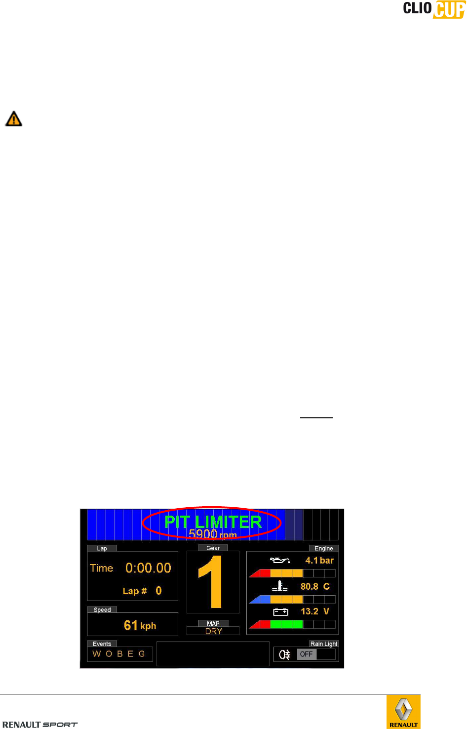
B.6.4.6 Pit limiter
The purpose of this function is to limit the vehicle's speed to 60kph. It is enabled and
disabled by the driver.
Principle:
By pressing the button “PIT” of the steering wheel, Engine revs are thus limited (by the
ECU) to those corresponding to a speed of 60kph and the message “PIT LIMITER” is
displayed on the dashboard in the RPM Area :
98CUP_2013 Release
C-24
If the pit limiter is activated while the current speed is > 60kph, all the Shiftlights flashes
together till the vehicle reach 60kph (at this particular moment, all shiftlights remains ON
but without flashing)
NOTE: The speed limiter does not control the brakes. Consequently, the vehicle speed
will only slow rapidly to 60kph if the driver applies the brakes.
To disable the pit limiter mode, the driver has to press the button “PIT” of the steering
wheel : the message “Pit Limiter” disappears on the display.
Specific conditions:
The driver may only enable and disable the speed limiter when the vehicle is in on a
forward gear (1 to 4)
B.6.4.7 Controlling the rain light
The rain light is switched on by flicking the “rain” switch to the up position (ON).
The central rear rain light is ON continuously when enabled.
However, it is lightning automatically with flashing phases (flashes at 0.5Hz) in the
following specific situations:
- When the Pit limiter is enabled
- For a period of 20 seconds after the engine stalls
- When Reverse Gear ratio is shifted
98CUP_2013 Release
C-25
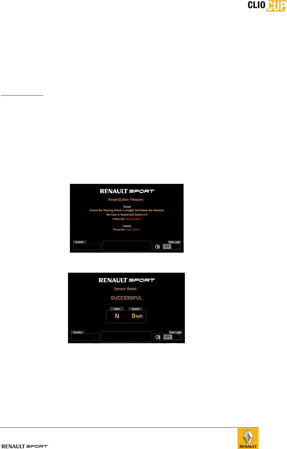
B.6.4.8 Resetting the chassis sensors
This procedure allows to reset the following sensors:
- Front Brake pressure sensor
- Rear brake pressure sensor
- Steering angle sensor
It is necessary to make a reset if one of the following sensor has been changed or if the
brake circuit has been bleeded.
CONDITIONS :
The car must be in the following configuration to allow the procedure:
- Engine stalled
- Gearbox in Neutral
- Speed = 0 kph
- Brake pedal released
- Steering wheel straight
- Car on a flat surface
• Press the “ON” button to power supply the car
• Display the “brake diagnostic” page
• Press the “RESET” button, the following message appears :
• press again the “RESET” button gain to start the procedure or “PAGE” button
(steering wheel) to cancel it
• Check in the “brake diagnostic” page that the value of :
Front BP = 0 bar
Rear BP = 0 bar
Steering angle = 0 °
This page only reminds
the conditions to
perform the RESET
procedure
98CUP_2013 Release
C-26
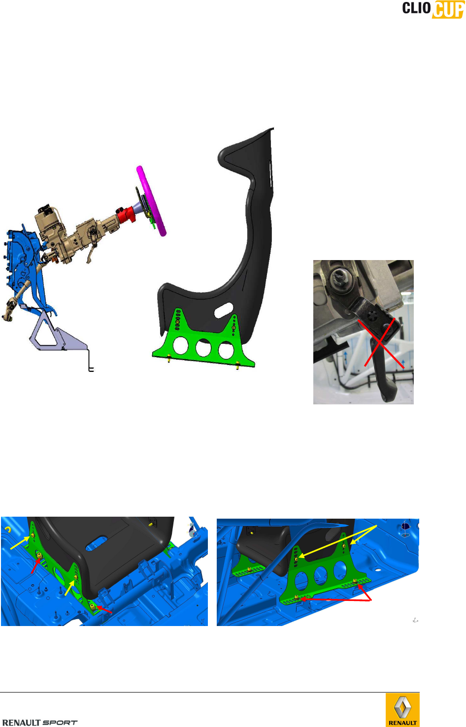
B.6.5 ADJUSTING THE DRIVING POSITION
B.6.5.1 Adjusting the steering wheel
To optimize the driving position, the height and deepness of the steering wheel may be
adjusted by unlocking the steering column lever (1)
NOTE :
After having set the
steering column position,
the adjustment lever
must be removed (1
screw to remove). It is
strictly forbidden to run
with it (FIA regulation)
B.6.5.2 Adjusting the seat
To move the seat forwards or backwards, place the seat in the required position and then
re-screw the brackets in the appropriate holes (2).
The height and angle of the seat may be adjusted the same way by altering its
attachment points on the brackets (3).
(2
)
(3)
98CUP_2013 Release
C-27
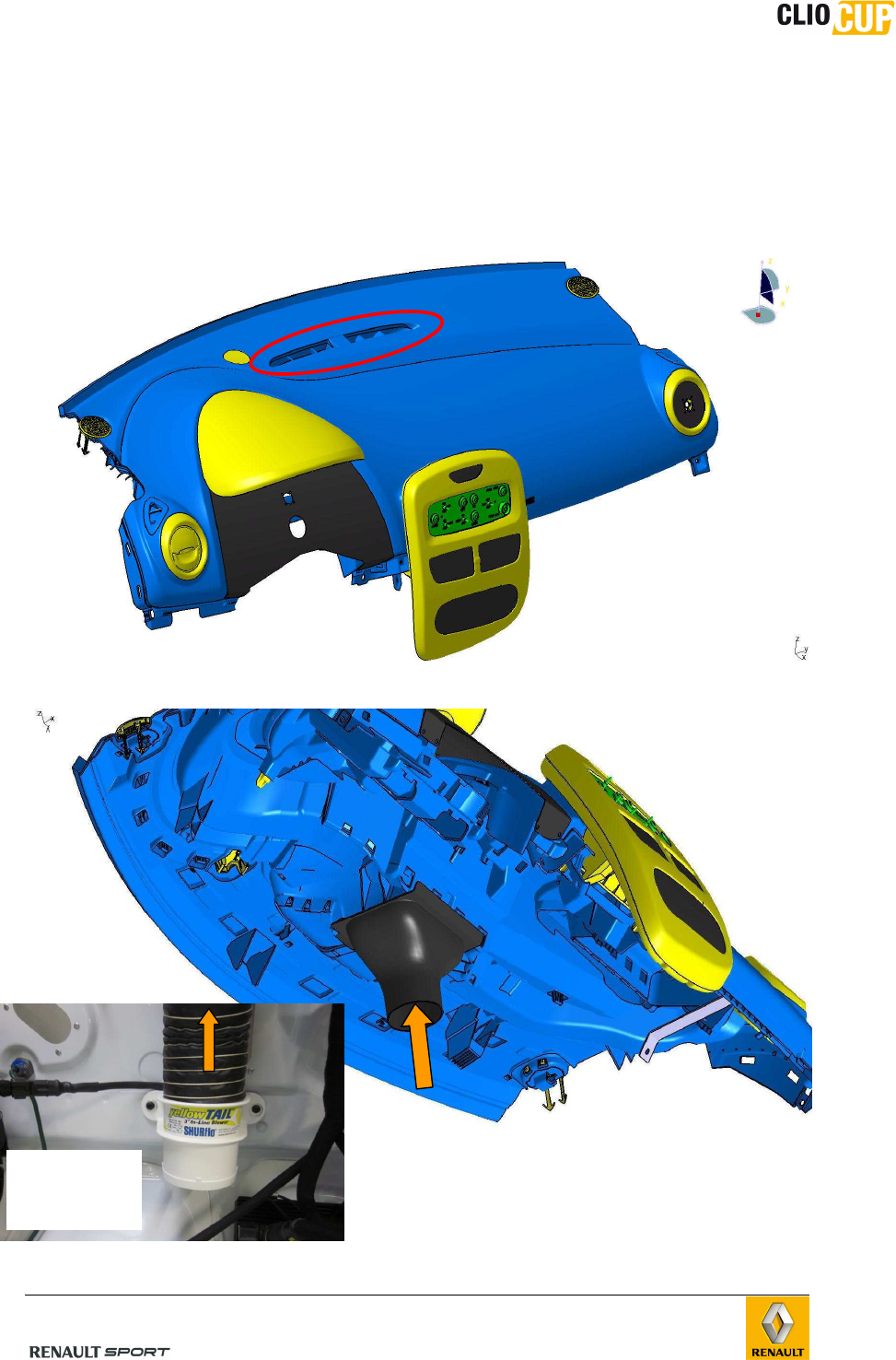
B.6.6 VENTILATION
The vehicle has 4 air vents:
• 1 in the middle of the facia : activated by the “heat” switch on facia switch panel
• 2 on the roof: air coming though the roof hatch
Ventilation on the facia upper surface:
View from below:
The air comes from the electric ventilator and is directed by the lower duct to the facia
Electric
ventilator fitted
on the engine
bulkhead
98CUP_2013 Release
C-28
Roof ventilation:
B.7 SAFETY EQUIPMENT
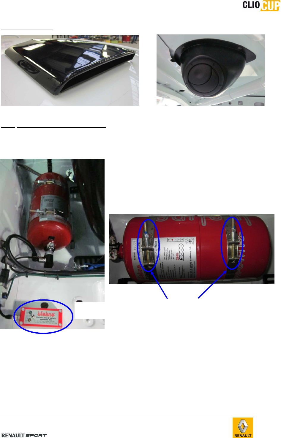
B.7.1 FIRE EXTINGUISHER
Each vehicle is equipped with an extinguishing
system targeting the driver compartment and the
engine compartment.
The fire extinguisher is located behind the driver’s
seat.
The fire extinguisher is fitted on its support using 2 metallic straps which are mandatorily
screwed (automatic clamping forbidden).
The fire extinguisher support is fitted on the chassis using 4 M6 screws (+2 spacers) + 4
nuts screwed under the chassis through plates (welded to the chassis)
Control unit
(3 positions)
2 mandatory
screwed clamps
Roof hatch
Inside aerator
98CUP_2013 Release
C-29
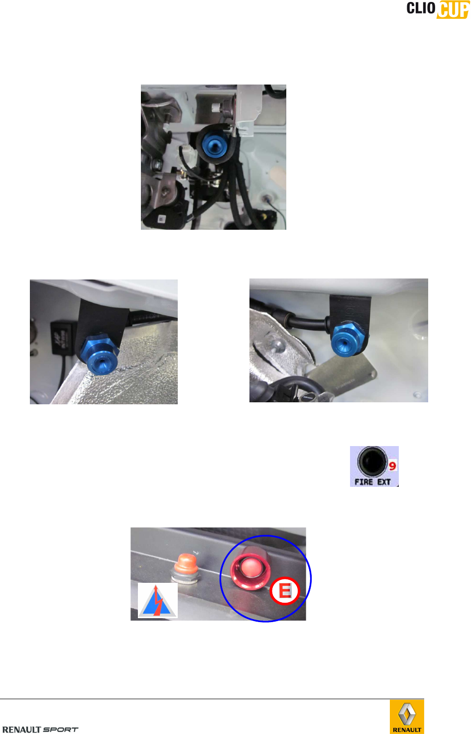
The system consists of 3 jets:
• In the driver compartment right hand side of the steering wheel
• 2 in the engine compartment
1 pointing on the Turbo : 1 pointing on the air intake :
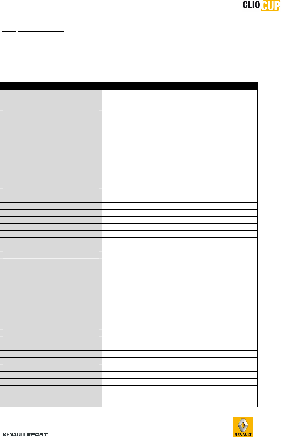
Use:
The extinguishing system can be triggered in 2 different ways:
• The driver presses on the button “Fire Ext” situated on the Facia
control panel (9)
• From Outside: by pressing the button (E) located on the outside of the vehicle at
the base of the windshield pillar, and which must be indicated by a red letter E.
98CUP_2013 Release
C-30
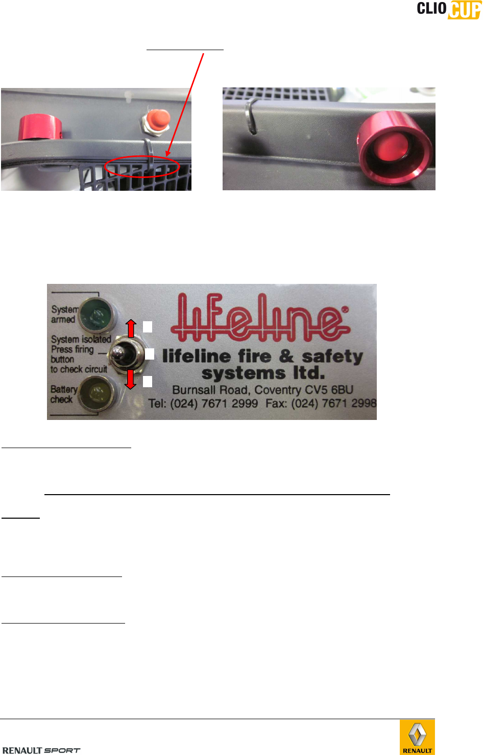
You must fit the wiring of the white connector directly on the plastic windscreen lower
grid using a tyrap® as indicated below:
The fire extinguisher is controlled by a deported control unit fitted on the central tunnel.
A specific fire extinguisher loom allows to link this control unit + fire extinguisher to the
chassis loom.
Position 1: system isolated
This position is to test the extinguisher loom. Everything must be correctly connected to
the loom. When you push the fire button (Facia switch panel or from outside deported
button), the green light must go ON but the extinguisher will not deploy.
NOTE : if the green light is ON without testing the system, there is a default on the
loom. In this case, you must be careful because the extinguisher is directly connected to
the command box. As a consequence, if you switch to position 3, you will immediately
deploy the extinguisher.
Position 2: battery check
If the orange light goes ON, the battery is ok.
Position 3: system armed
“System armed” means that if you push the fire button (Facia switch panel or from
outside deported button), you will immediately deploy the extinguisher.
The green light goes ON only when the extinguisher is deployed.
3
1
2
deported
control unit
98CUP_2013 Release
C-31
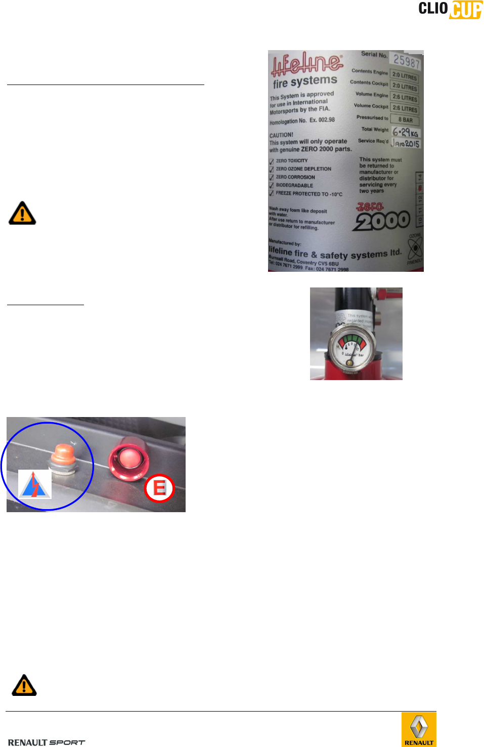
Checks
- Extinguisher cylinder compliance check:
The following information must be clearly
visible on the cylinder:
• Serial number.
• Capacity and weight or volume of
extinguisher product.
• Activation date or date of last system check.
• Date of next service.
• Homologation number.
Take care not to exceed the extinguisher’s
next scheduled service date.
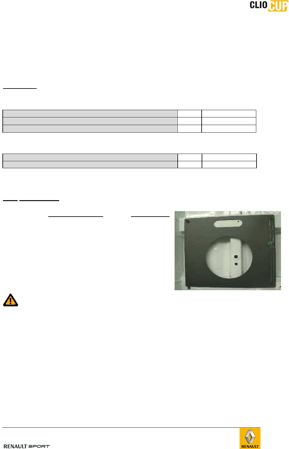
- Pressure check
The pressure of the cylinder may be checked using a
manometer placed on the cylinder.
The needle must be situated in the green area on the
manometer dial.
B.7.2 CIRCUIT BREAKER
There is an emergency circuit breaker control at
the base of the windshield pillar. It must be
indicated by a sticker with a red lightening symbol
on a blue background. This button may be used to
switch off the vehicle’s electrics from the outside.
B.7.3 OTHER SAFETY EQUIPMENT
- The presence of the window safety net (ref. 77 11 160 041) on the driver side of
the roll cage is mandatory.
- It is mandatory for foam (ref 77 11 160 040) to be placed on all parts of the roll
cage with which the driver’s helmet may come into contact.
- The seats (original part ref: 77 11 167 158 and XL version part ref: 77 11 167
160) and the harness (ref 77 111 167 161) are compatible with FHR system.
The use of « FHR » system must be in compliance with the installation
standard of FIA.
98CUP_2013 Release
C-32
B.7.4 PASSENGER SEAT
A passenger seat may be installed on Clio Cup using the supports with part ref
8201380465 and 8201380466
The seats references remain the same as for driver side.
Fasteners:
Seat supports on the chassis:
Screws CHC10-25 x 4 77 11 156 901
Contact washer Ø10X22 x 4 77 11 156 926
Flat washer Ø10,25X26 ép:3 cl:10.9 x 4 77 03 053 341
Seat on the support :
Screws M8-35 cl.12,9 x 4 77 11 154 904
Contact washer Ø8X18 x 4 77 11 156 945
B.8 BALLAST
To respect the minimum weight and the race weight
(refer to technical regulation and Nomenclature), some
ballast may be fitted.
Only the following ballast must be used:
- 1kg: ref 77 11 160 299
- 2kg: ref 77 11 160 300
- 5kg: ref 77 11 160 301
These plates must be mounted using two drilled head
bolts with part ref 77 11 160 302 (sold in sets of 2).
In all cases, these ballast plates will be fitted at the passenger seat rail sites,
(refer to the current Technical Regulations and Nomenclature).
98CUP_2013 Release
C-33
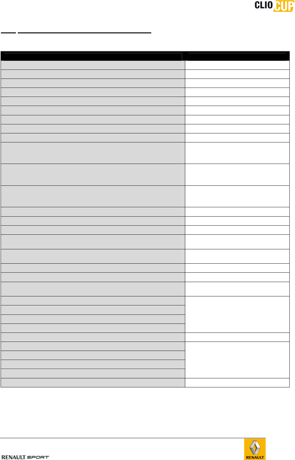
B.9 APPENDIX
B.9.1 LIST OF MARKED PARTS
All parts that are specific to Clio Cup are engraved.
The following genuine Renault parts are identified either by a “Renault Sport” laser
engraving or by a hologram (its presence is compulsory with NO PAINT)
PART NAME REFERENCE “RENAULT SPORT”
HOLOGRAM
Engine bulkhead heat shield 67900 6317 R X
Front shock absorber 98CUP00040 X
Rear Wing 8201380868 X
Battery 7711127895 X
Rear spoiler 96030 5963 R X
Airbox 8201378943 X
Steering column 8201372112 X
Air intake duct 8201409155 X
Left lower air Guide 21469 1078 R X
Left air guide 21559 0558 R X
Right air guide 21558 9177 R X
Roof inside aerator 77 11 160 315
X
Battery cover 77 11 162 704
X
Dashboard Cosworth ICD 82 01 372 416
X
ECU Cosworth SQ7 82 01 381 101
X
Front left door inside cover 82 01 382 021
X
Front right door inside cover 82 01 382 023
X
Facia air duct 82 01 389 867
X
Fire extinguisher 82 01 396 046
X
Water Fan 214819617R X
Rear spoiler lower cover 960303776R X
Turbo air exchanger 98CUP00006 X
Complete fuel tank 98CUP00008 X
Water cooler 98CUP00009 X
Front Right headlight 98CUP00015 X
Front Left headlight 98CUP00017 X
Rear Right light on rear cover 98CUP00022 X
Rear Left light on rear cover 98CUP00024 X
FR door window 98CUP00058 X
FL door window 98CUP00059 X
RR door window 98CUP00061 X
RL door window 98CUP00062 X
RR quarter window 98CUP00063 X
RL quarter window 98CUP00064 X
Rear bumper skin 98CUP00065 X
Rear window 98CUP00068 X
Right rearview mirror 98CUP00070 X
Left rearview mirror 98CUP00071 X
Left rearview mirror cover 98CUP00072 X
Right rearview mirror cover 98CUP00073 X
Windscreen 98CUP00084 X
Roof hatch 82 01 383 889
X
Front crossbeam 752107246R X
rear air diffuser 960302211R X
FR mudguard 98CUP00074 X
98CUP_2013 Release
C-34
FL Mudguard 98CUP00075 X
FR door 98CUP00076 X
FL dooe 98CUP00077 X
Front cover 98CUP00080 X
Rear cover 98CUP00081 X
Fuel pump / gauge 98CUP00093 X
RR door 98CUP00078 X
RL door 98CUP00079 X
Gearbox command rod 809mm 8201418758 X
Gearbox command rod 784mm 8201418759 X
Rear camber/alignment shim 10’
8201369770 X
Rear camber/alignment shim 20’
8201369771 X
Rear camber/alignment shim 30’
8201369772 X
Rear camber/alignment shim 1° 8201369773 X
Anti-roll bar 54611 9898 R X
Anti-roll bar rod 8201079463 X
Front master cylinder 19,1mm 77 11 158 019
X
Rear master cylinder 20.6mm 77 11 158 025
X
Gearbox manual lever 77 11 160 560
X
Clutch mechanism 77 11 160 633
X
FR calliper 77 11 160 362
X
FL Calliper 77 11 160 363
X
FL upright 77 11 160 481
X
FR upright 77 11 160 480
X
Turbo upstream pipe 82 01 370 056
X
Flywheel 82 01 350 850
X
AP clutch disc 82 01 370 335
X
Front brake disc AP 320x28 82 01 395 136
X
Front calliper support 82 01 403 772
X
Front hub 432000010R X
Subframe crossbeam 82 00 537 434
X
RR central hub 98CUP00035 X
RL central hub 98CUP00036 X
FR wishbone 82 01 361 749
X
FL wishbone 82 01 361 750
X
Front brake pad RC6ER 8201442791 X
Rear brake pads RC6 77 11 162 956
X
Rear brake pads RC5+ 77 11 162 954
X
98CUP_2013 Release
C-35
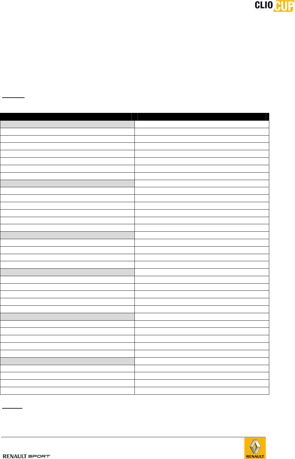
B.9.2 REPLACEMENT OF MECHANICAL COMPONENTS
The mileage of the below parts must be monitored by the user throughout the vehicle’s
lifetime.
The mileage stated in the table below is the maximum expected mileage before
replacement, notwithstanding any incidents or accidents.
Should any component become faulty or its condition deteriorate before reaching the
stated mileage, please contact Renault Sport Technologies.
NOTE : This list may not under any circumstances be considered to be part of the
manufacturer’s warranty.
Parts Recommanded milage
Front axle
Point E and Point F ball joint 5000 km
Wishbone ball joints 3000 km
Wheel bearing 5000 km
Shock absorbers + Bump stop 5000 km
Support strut 10000 km
Anti-roll ball joint 7000 km
Wheel stud and nut 5000 km
Rear Axle
Point F ball joint 7000 km
Point E ball joint 7000 km
Point A ball joint 7000 km
Wheel bearing 5000 km
Shock absorbers + Bump stop 5000 km
Wheel stud and nut 5000 km
Steering
Power steering module 15000 km
Steering rack 7500 km
Steering rod ball joint (point H) 7000 km
Rack ball joint 7000 km
Transmission
Gearbox 7500 km
Clutch friction 4500 km
Clutch mecanism 4500 km
Slave cylinder bearing 5000 km
Driveshafts 5000 km
Engine
Engine / Turbo / HP pump / WG / pop off 10000 km
Starter / alternator 10000 km
Engine + Gearbox mountings 10000 km
Motorised Throttle 6000 km
Gas Pedal potentiometer 10000 km
Brakes
Front brake disc 1500 km
Front brake caliper 6000 km
Rear brake disc 8000 km
Rear brake calliper 8000 km
NOTE: Particular attention must be paid to the state of the fasteners after any work has
been carried out.
