Renishaw plc RMI INTERFACE FOR MACHINE TOOLS User Manual H 2000 5220 01 A RMI cover web pmd
Renishaw plc INTERFACE FOR MACHINE TOOLS H 2000 5220 01 A RMI cover web pmd
UserManual.wiki
>
Renishaw plc
>
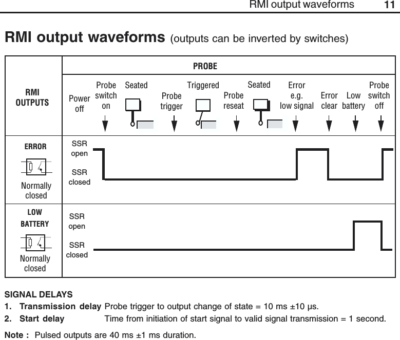
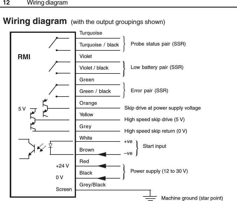
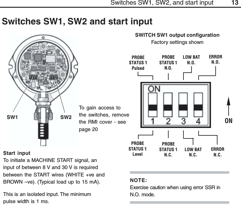
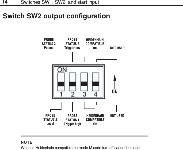
RMI User Manual
USER GUIDE
Navigation menu
Upload a User Manual
Namespaces
Wiki Guide
HTML
PDF
Info
Views
User Manual
Discussion / Help
Navigation