Renishaw plc RMI INTERFACE FOR MACHINE TOOLS User Manual H 2000 5220 01 A RMI cover web pmd
Renishaw plc INTERFACE FOR MACHINE TOOLS H 2000 5220 01 A RMI cover web pmd
USER GUIDE

Installation and user’s guide
H-2000-5220-01-A
RMI - radio machine interface
© 2003 Renishaw. All rights reserved.
Renishaw® is a registered trademark of
Renishaw plc.
This document may not be copied or
reproduced in whole or in part, or
transferred to any other media or language,
by any means, without the prior written
permission of Renishaw.
The publication of material within this
document does not imply freedom from
the patent rights of Renishaw plc.
Renishaw part no: H-2000-5220-1-A
Issued: 08.2003
Disclaimer
Considerable effort has been made to ensure
that the contents of this document are free from
inaccuracies and omissions. However, Renishaw
makes no warranties with respect to the
contents of this document and specifically
disclaims any implied warranties. Renishaw
reserves the right to make changes to this
document and to the product described herein
without obligation to notify any person of such
changes.
Trademarks
All brand names and product names used in
this document are trade names, service marks,
trademarks, or registered trademarks of their
respective owners.

1
EC DECLARATION OF CONFORMITY
Renishaw plc declare that the product:-
Name: RMI
Description: Radio Machine Interface
has been manufactured in conformity with the following standard: -
BS EN 61326:1998/ Electrical equipment for measurement, control and
laboratory use - EMC requirements.
Immunity to annex A - industrial locations.
Emissions to class A (non-domestic) limits.
and that it complies with the requirements of directive (as amended): -
89/336/EEC Electromagnetic compatibility
The above information is summarised from the full EC declaration of
conformity. A copy is available from Renishaw on request.

2Installation and user’s guide
Installation and user’s guide
Warranty
Equipment requiring attention under warranty
must be returned to your supplier. No claims will
be considered where Renishaw equipment has
been misused, or repairs or adjustments have
been attempted by unauthorised persons.
Care of the RMI
Keep system components clean and treat the
RMI with care.
Do not apply metallic labels to the front of the RMI.
Changes to equipment
Renishaw reserve the right to change
specifications without obligation to change
equipment previously sold.
Weight
RMI including 15 metres (49.2 ft) of cable
= 1,700 g (60 oz).
CNC machine
CNC machine tools must always be operated
by competent persons in accordance with
manufacturers instructions.
Environment
Temperature
The RMI is specified for storage over
–10° to 70° C (14° to 158° F) and operation
over 5° to 60° C (41° to 140° F) ambient
temperature range.
Sealing
The unit is fully sealed to IPX8.
Patent notice
Features of products shown in this guide,
and of related products, are the subject of the
following patents and/or patent applications:
EP 0652413
US 4599524
US 5,279,042
JP 3,126,797
WO 02/063235
WO 03/021182
!CAUTION: Only qualified persons should
adjust switches.

3
Contents
Contents
RMI .................................................................. 4
Operating envelope ......................................... 5
RMI visual diagnostics .................................... 6
RMI outputs ..................................................... 8
RMI output waveforms .................................. 10
Wiring diagram .............................................. 12
Switches SW1, SW2 and start input ............. 13
RMI cable ...................................................... 15
RMI cable sealing and fitting
flexible conduit ............................................... 16
RMI-RMP partnership ................................... 17
Installation with inspection and
tool setting probe ........................................... 18
Remote external audible output .................... 19
Mounting bracket .......................................... 20
Removing and refitting the RMI cover .......... 21
Removing and refitting PCB .......................... 23
Side to rear exit conversion .......................... 23
Screw torque values ..................................... 24
Parts list ......................................................... 25
4
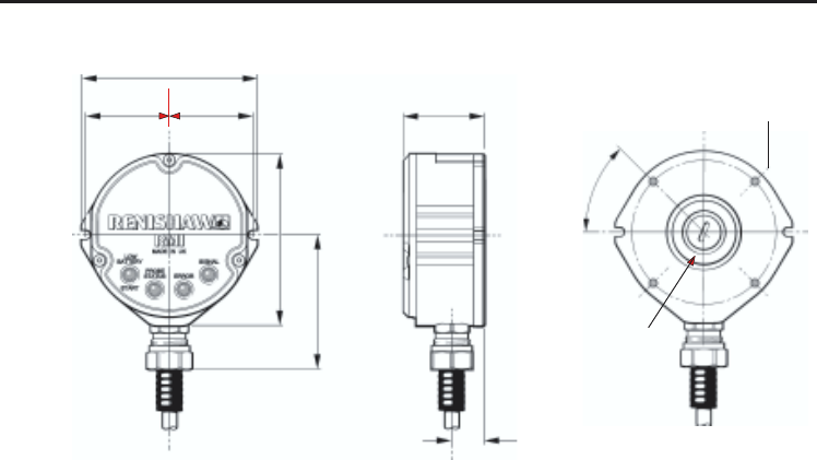
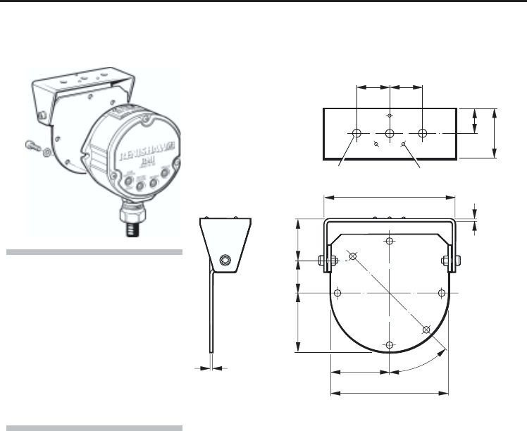
RMI
The RMI is a combined radio tranceiver and
machine interface.
The RMI is designed to be mounted within
the machine's working envelope.
Power supply
The RMI can draw its supply from the CNC
machine 12 V to 30 V d.c. supply and presents a
RMI
peak load of up to 250 mA during turn on
(typically 100 mA from 24 V).
Alternatively, power may be supplied from
a Renishaw PSU3 power supply unit.
Input voltage ripple
The input voltage ripple shall not cause the
voltage to fall below 12 V, or rise above 30 V.
RMI
46 (1.81)
97 (3.82)
46 (1.81)
45 (1.77)
44 (1.73)
50 (1.97)
74 (2.91)
17.5 (0.69)
dimensions mm (in)
45°
4 holes M5 x 13
deep on 80 p.c.d.
To use a flush rear
exit a 25 (1.0) hole
is required for
connector
5
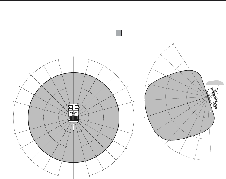
Operating envelope
Operating envelope
RMP60 probe + RMI
RMP60 and RMI must be within each others
operating envelope shown.
Range metres (feet)
OPERATING AND SWITCH ON/OFF
90°
75°
60°
45°
30°
15°
0°
15°
30°
45°
60°
75° 90° 75°
60°
45°
30°
15°
0°
15°
45°
60°
75°
75°
60°
45°
30°
30°
45°
60° 75°
10 (33)
15 (49)
5 (16)
5
(16)
10
(33)
15
(49)
10 10
(33) (33)
15 15
(49) (49)
15°
5
(1 6)
6
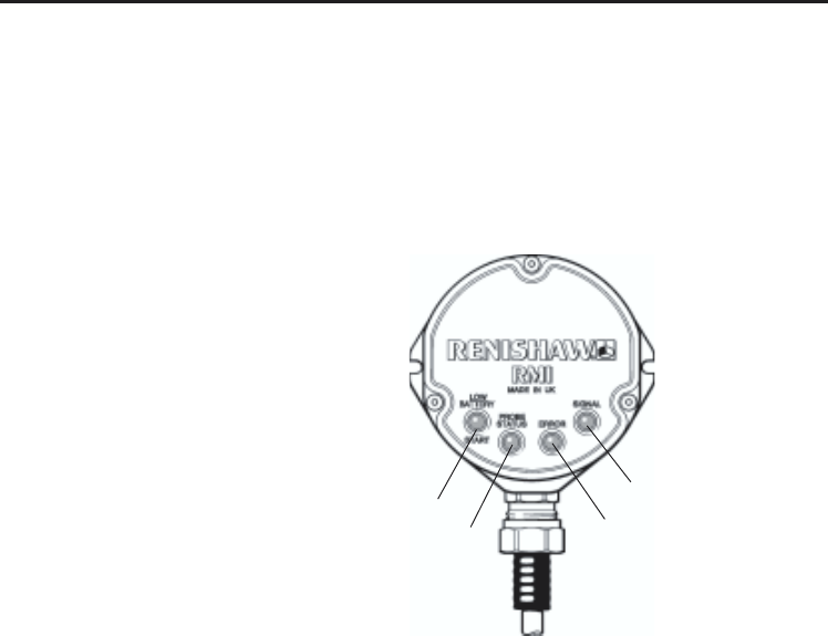
A visual indication of system status is provided by LED's.
Status is continuously updated and indication is provided for
START, LOW BATTERY, PROBE STATUS, ERROR, SIGNAL STRENGTH
KEEP THE
FRONT COVER
CLEAN
3
1
2
4
RMI visual diagnostics
RMI visual diagnostics
LED LIGHT SIGNALS
1. LOW BATTERY
Red Battery is low.
Green M code start/stop in
progress.
Yellow Battery low & M code
start/stop in progress.
Off Battery is O.K. (and no
M code start/stop in
progress).
2. PROBE STATUS
Red Probe triggered or unknown
status.
Green Probe is seated.

7
RMI visual diagnostics
3. ERROR
Red Error, other outputs may
be incorrect.
Off No Error.
4. SIGNAL
Green Full signal strength.
Yellow Medium signal strength.
Red Low signal strength, radio
link may fail.
Off No signal detected.
Green/off Flashing: RMI is acquisition
mode, and can acquire a
partner RMP.
Red/yellow Flashing: RMI has (just)
acquired a new partner RMP.
Notes.
1. The probe status LED will always be
illuminated when power is present.
There is no ‘power present’ LED.
2. All the indicators report the status of the
partner RMP. If there is no partner in range,
or the partner is off then the probe status
and error LEDs will be red and the other
LEDs will be off.
3. When the RMI is powered it will enter the
acquire partner mode which will be indicated
by the flashing green signal LED.
After a short time (~12 secs) it will switch to
its normal mode listening for its partner.
4. The conditions shown by the low battery,
probe status and error LEDs are the same
as those present on the electrical signal
outputs.

8
RMI outputs
There are four outputs:
Probe status 1 (SSR)
Probe status 2a (driven skip 5 V isolated)
Probe status 2b (driven at power supply
voltage)
Error (SSR)
Low battery (SSR)
All outputs can be individually inverted by using
switches SW1 and SW2 - see pages 16 and 17.
Switching time = Less than 10 µs (low to high)
Switching time = Less than 10 µs (high to low)
If overload occurs, remove source or problem,
turn off power supply and the unit will reset itself.
.
RMI outputs
SSR outputs:
DC ‘ON’ resistance 60 ohms max.
Up to 50 mA protected.
Switching time = Less than 10 µs (low to high)
Switching time = Less than 10 µs (high to low)
Power supply reversal will not damage the
SSR outputs, but may trip the electronic
over current circuits.
Driven outputs:
Sourcing - Up to 50 mA protected.
Sinking - Up to 50 mA unprotected, but
overload will still be indicated by
LEDs.

9
RMI outputs
CAUTION:
Power supply voltage
Do not exceed 30 V between the black wire and the screen wire (grey/black), or the red
wire and screen wire (grey/black), or the red and black wires (power supply), as this could
result in permanent damage to the RMI and/or the customer power supply.
The use of in-line fuses at the machine cabinet end is recommended to provide protection
for the RMI and cable
Screen connection
A good connection should be made to machine ground (star point).
Output stage circuit
Output stage supplies (+ve, –ve) should not be switched on and off to enable/disable them
as this can cause the over current protection to switch off the output completely.
Ensure that outputs from the RMI do not exceed specified current ratings.
!
RMI outputs
!
!
10
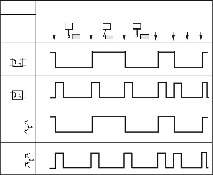
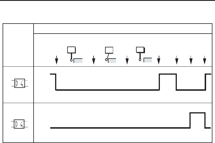
Output
high
Output
low
RMI output waveforms
Probe
switch
on
Seated
Power
off
Probe
trigger
Triggered
Probe
reseat
Seated Error
e.g.
low signal
Error
clear
SSR
open
SSR
closed
Normally closed
Probe
switch
off
Low
battery
PROBE
PROBE STATUS 1
(LEVEL)
RMI
OUTPUTS
SSR / driven
output
(switch
position)
Normally closed
Normally low
PROBE STATUS 2
(LEVEL)
SSR
open
SSR
closed
Normally low
PROBE STATUS 1
(PULSED)
PROBE STATUS 2
(PULSED) Output
high
Output
low
11
Probe
switch
on
Seated
Power
off
Probe
trigger
Triggered
Probe
reseat
Seated Error
e.g.
low signal
Error
clear
SSR
open
SSR
closed
Normally
closed
Normally
closed
SSR
open
SSR
closed
Probe
switch
off
Low
battery
PROBE
ERROR
LOW
BATTERY
SIGNAL DELAYS
1. Transmission delay Probe trigger to output change of state = 10 ms ±10 µs.
2. Start delay Time from initiation of start signal to valid signal transmission = 1 second.
RMI output waveforms (outputs can be inverted by switches)
RMI
OUTPUTS
RMI output waveforms
Note : Pulsed outputs are 40 ms ±1 ms duration.
12
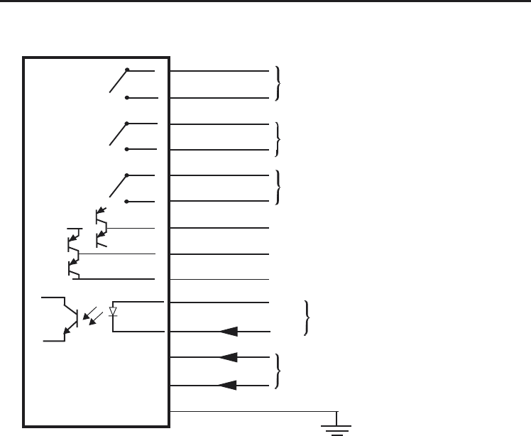
Turquoise
Turquoise / black
Violet
Violet / black
Green
Green / black
Orange
Yellow
Grey
White
Brown
Red
Black
Grey/Black
Wiring diagram (with the output groupings shown)
+24 V
0 V
Screen
RMI
+ve
–ve
Start input
Power supply (12 to 30 V)
Machine ground (star point)
Wiring diagram
Skip drive at power supply voltage
High speed skip drive (5 V)
High speed skip return (0 V)
Probe status pair (SSR)
Low battery pair (SSR)
Error pair (SSR)
5 V
13
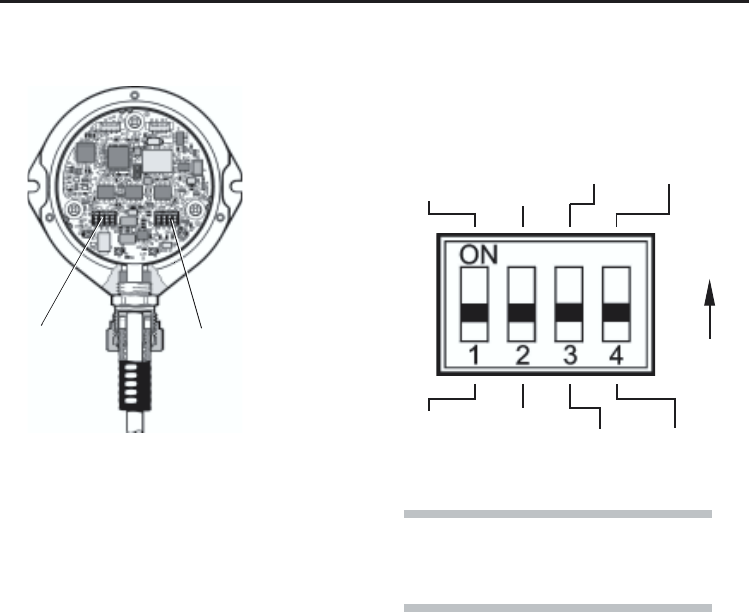
ON
LOW BAT
N.O.
LOW BAT
N.C.
SWITCH SW1 output configuration
Factory settings shown
Start input
To initiate a MACHINE START signal, an
input of between 8 V and 30 V is required
between the START wires (WHITE +ve and
BROWN –ve). (Typical load up to 15 mA).
This is an isolated input. The minimum
pulse width is 1 ms.
To gain access to
the switches, remove
the RMI cover - see
page 20
SW1 SW2
PROBE
STATUS 1
Pulsed
PROBE
STATUS 1
N.O.
PROBE
STATUS 1
Level
PROBE
STATUS 1
N.C.
Switches SW1, SW2 and start input
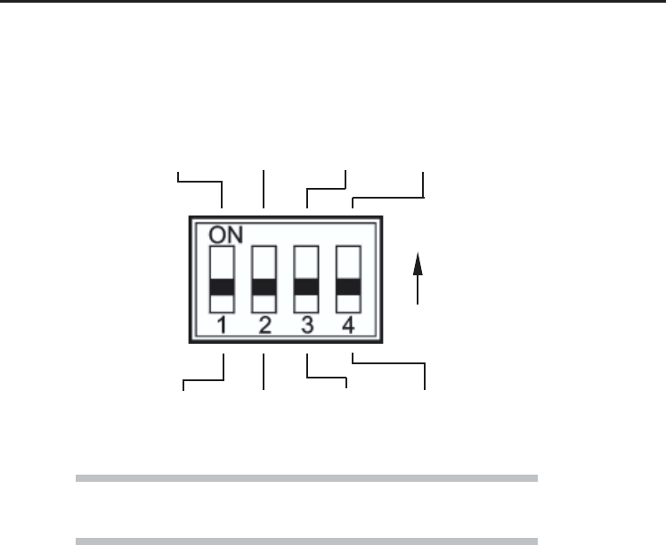
ERROR
N.O.
ERROR
N.C.
Switches SW1, SW2, and start input
NOTE:
Exercise caution when using error SSR in
N.O. mode.
14
Switch SW2 output configuration
ON
HEIDENHAIN
COMPATIBLE
On
PROBE
STATUS 2
Pulsed
PROBE
STATUS 2
Trigger low
HEIDENHAIN
COMPATIBLE
Off
PROBE
STATUS 2
Level
PROBE
STATUS 1
Trigger high
Switches SW1, SW2, and start input
NOT USED
NOT USED
NOTE:
When in Heidenhain compatible on mode M code turn off cannot be used
15
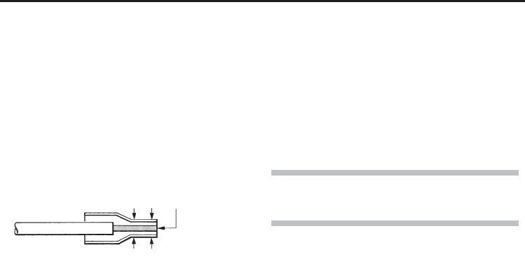
Core end flush
with ferrule
Core
Ferrule
Crimp
Cable termination
A ferrule should be crimped onto each cable
core for more positive connection at the terminal
box. To fit a ferrule, insert the prepared core into
ferrule, until the end is flush with the end of the
ferrule as shown below. Then crimp with pliers.
NOTE:
Maximum total cable length is 50 m (164 ft) at 24V
Standard cable
The RMI standard cable is 15 m (49.2 ft) long,
longer cables are avaible (see page 25).
Cable specification:
Ø7.5 mm (0.29 in), 13 core screened cable,
each core 18 x 0.1 mm.
RMI cable
RMI cable
16 RMI cable sealing and fitting flexible conduit
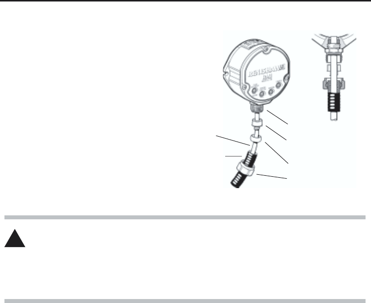
Fitting flexible conduit
Cable
Flexible
conduit
Adaptor A
Conduit termination
piece
Plastic olive
Nut B
CAUTION: Failure to adequately protect the cable can result in system failure due to either
cable damage or coolant ingress through cores into the RMI.
Failure due to inadequate cable protection will invalidate the warranty.
When tightening or loosening nut B onto conduit ensure that torque is only applied between
A and B.
Coolant and dirt are prevented from entering the
RMI by the cable sealing gland. The RMI cable
is protected against physical damage by fitting
flexible conduit if required.
RMI cable sealing
!
Recommended flexible conduit is Anamet
sealtite HFX (5/16 in) polyeurethane).
1. Slide nut B and plastic olive onto conduit.
2. Screw conduit termination piece into end of
conduit.
3. Fit conduit to adaptor A and tighten nut B.

17
Set up is done by using the RMP trigger logic
and powering on the RMI at a particular time
during the process.
1. Use trigger logic to set RMP turn on/ off
modes as desired.
2. Use trigger logic to access RMP acquisition
mode (turquoise/light blue flashes 2 short
and 1 long).
System setup/establishing RMP-RMI partnership.
RMP-RMI partnership
3. Power on the RMI.
4. Wait until RMI signal led flashes green.
WARNING:
When holding the RMP do NOT wrap a
hand, or anything else, around the glass
window.
!
5. Trigger the probe (min 0.1 sec, max 2 sec).
6. When the partnership is established the
RMI signal LED will flash red and yellow.
7. Allow ~10 seconds for both RMP and RMI
to timeout, all RMP LEDs off, RMI signal
LED off. The system is then ready for use.
8. Note: If the RMP flashes 2 turquoise short
followed by 1 red long it is still trying to
partner an RMI.
Note:
When the RMP and RMI become partners the
RMI records the RMP serial number. It is not
possible for an RMI to be partners with more than
one RMP.
It is possible for an RMP to be partners with more
than one RMI, but the system will not
work correctly if more than one partner RMI is
powered on at any one time.
18
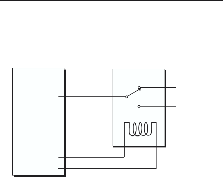
On machines where the RMI is to be integrated with a tool setting probe input,
and only one probe input is provided on the control, an M code can be utilised
to drive an external relay and effectively select which probe is to be monitored :
CONTROL
PROBE INPUT
M CODE
Installation with inspection and tooletting probe
Probe status
from tool setter
Probe status
from RMI
RELAY
Installation with inspection and tool setting probe
19
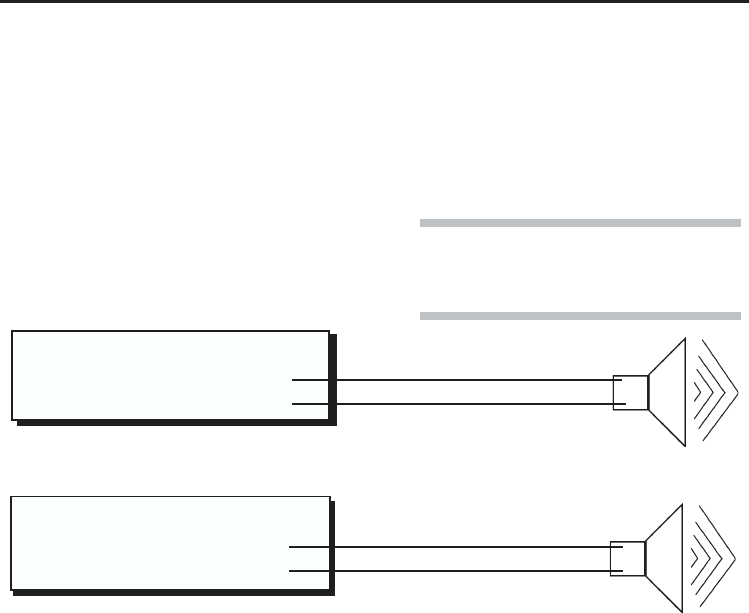
Orange
Black
Skip drive (power supply)
0 V
+ve
–ve
Yellow
Grey
Pulsed (skip)
0 V
+ve
–ve
Note: This is not possible if both skip
drives are being monitored by
the control
The pulsed output can be utilized to operate
an external remote audible indicator.
Wiring configurations are shown below.
Remote external audible output
Remote external audible autoput
RMI
RMI
Option 1. Using 5 V output
Option 2. Using machine voltage output
OR
The audible indicator must comply with the
output transistor specification
i.e. 50 mA peak
30 V peak
Pulse duration is 40 ms ±1 ms.
20
Mounting bracket (optional)
3 holes Ø6.4 (0.25)
25
(0.98)
25
(0.98)
19 (0.75)
38 (1.50)
45
(1.77)
25
(0.98)
30
(1.18)
3 grip protrusions
100,5 (3.95)
90 (3.54)
2.0
(0.08)
6 holes
Ø5.3 (0.20)
2.0
(0.08) Paired holes permit RMI mounting
in alternative orienation.
45 (1.77) 45°
Mounting bracket
dimensions mm (in)
NOTE:
Install RMI with cable exiting from
lower side for good coolant run off.
Mounting bracket cannot be used
with an RMI in rear exit configuration.
Do not apply any metallic label to
the front cover, as this will shield
the antenna.

21
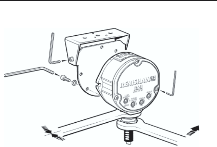
Fitting the RMI cover
1. Before fitting the cover, check for any
damage to screws or scratch marks which
could prevent sealing.
2. Ensure that the 'O' ring seating on the RMI
body is clean, and there are no scratch
marks which could prevent complete
sealing.
3 Ensure that the cover, antenna contacts
and 'O' ring are clean.
4. Place cover complete with 'O' ring
onto the RMI body.
Note :
The 'O' ring should be lubricated with
silicone grease to prevent nicking.
Do not get any grease on the antenna
contacts.
5. Tighten each captive screw a few turns at
a time, to pull the cover down evenly.
Screw torque is 1.4 Nm (1.03 lbf.ft).
It is not necessary to remove the RMI from
the machine, when adjusting the switches or
installing new parts. For torque settings please
see page 24.
Removing the RMI cover
1. Clean RMI to ensure no debris enters unit.
2. Unscrew the three captive cover screws
evenly (2 mm key).
3. When removing cover DO NOT twist or
rotate by hand.
RMI cover
Removing and refitting the RMI cover
22 Removing and refitting the RMI cover
RMI cover
CAUTION:
KEEP RMI CLEAN No liquids or solid particles must be allowed to enter the RMI body.
DO NOT allow the antenna contacts to be contaminated.
!
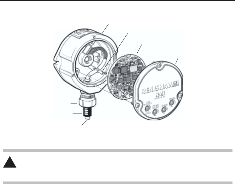
PCB
RMI body
Conduit adaptor
Conduit
Cable
Cable clamp

23
Removing and refitting PCB / Side to rear exit conversion
Removing and
refitting PCB
To remove PCB
1. Remove the RMI cover (page 20).
2. Remove 3 crosshead screws retaining
PCB. Carefully remove PCB and
disconnect cable connection to PCB.
To fit PCB
1. Connect PCB to cable connector. Insert
PCB and retain with 3 cross head screws.
2. Replace RMI cover (page 20).
1. Remove RMI cover (page 20)
2. Remove PCB.
3. Unscrew cable clamp (2 x crosshead
screws).
4. Unscrew conduit gland from RMI body.
5. Unscrew rear exit plug and rubber gromit
from RMI body.
6. Carefully remove cable assembly and refit
through rear exit hole. Tighten conduit gland.
7. Fit rubber gromit and rear exit plug to side
exit hole and tighten.
8. Fit cable assembly using cable clamp at
3 o’clock position.
9. Replace PCB.
10. Replace RMI cover (page 20).
Side exit cable to rear exit
cable conversion
CAUTION
TAKE CARE HANDLING THE PCB
Hold edge of PCB only, do not
touch surface components
!
24
4 mm AF
5.1 Nm
(3.76 lbf.ft)
HOLD
3 mm AF
2 Nm
(1.47 lbf.ft)
22.2 mm AF (7/8 AF)
Screw torque values Nm (lbf.ft).
Screw torque values
2 mm
1.4 Nm
(1.03 lbf.ft)
Conduit adaptor to RMI body
10 Nm (7.38 lbf.ft)
Rear exit plug (not shown)
10 Nm (7.38 lbf.ft)
19 mm AF

25
RMI A-4113-0050 RMI with 15 m (49.2 ft) of Cable.
Mtg Brkt A-2033-0830 Mounting bracket.
Cover A-4113-0105 Cover/anntenna asembly: including cover screws and O ring.
Cable assy A-4113-0101 Cable assembly 15 m (49.2 ft) long.
Cable assy A-4113-0106 Cable assembly 30 m (98.4 ft) long.
Cable assy A-4113-0107 Cable assembly 50 m (164 ft) long.
PCB A-4113-0520 RMI circuit board
Tool kit A-4113-0104 2mm hex key, 4 mm hex key, 14 x ferrules, 4 x M5 screw,
2 x M5 nut, 4 x M5 washer, O ring (34.5 x 3 mm)
Type Part No. Description
The serial number of each RMI is found at the top of the housing.
Parts list - Please quote the Part no. when ordering equipment.
Parts list

Renishaw plc
New Mills, Wotton-under-Edge,
Gloucestershire, GL12 8JR
United Kingdom
T+44 (0)1453 524524
F+44 (0)1453 524901
Euk@renishaw.com
www.renishaw.com
For worldwide contact details,
please visit our main website at
www.renishaw.com/contact
*H-2000-5220-01-A*