Renishaw plc RMI-Q RMI-Q Radio Machine Probe User Manual Manual 1
Renishaw plc RMI-Q Radio Machine Probe Manual 1
UserManual.wiki
>
Renishaw plc
>
RMI-Q User Manual
>
Manual 1
Contents
1.
Manual 1
2.
Manual 2
Manual 1
Navigation menu
Upload a User Manual
Namespaces
Wiki Guide
HTML
PDF
Info
Views
User Manual
Discussion / Help
Navigation


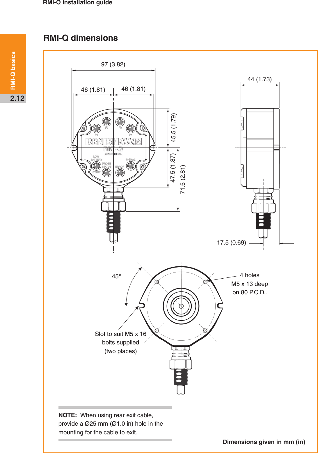


![RMI-Q installation guide3.2System installationWiring diagram (with output groupings shown)12 V to 30 VTurquoiseVioletGreenTurquoise/blackViolet/blackGreen/blackWhitePinkWhite/redBrownYellow SignalReturnSee NOTEOrangeRedBlackGreenGreyWhite/blueRMI-QMachine ground (star point)Power supply (12 V to 30 V)Error (SSR)Probe status 1 (SSR)Low battery (SSR)Machine start input [P1]Machine start input [P2]Machine start input [P3]Machine start input [P4]Machine start commonProbe status 2b! CAUTION: The power supply 0 V should be terminated at the machine ground (star point). A negative supply can be used when wired appropriately.DriverScreenDriver Probe status 2a(5 V isolated driven skip)5 V0 VNOTE: A switch can be added on installation to aid with powering up the RMI-Q when partnering.}}}}}](https://usermanual.wiki/Renishaw-plc/RMI-Q.Manual-1/User-Guide-1803640-Page-26.png)