Renishaw plc RMI-Q RMI-Q Radio Machine Probe User Manual Manual 1
Renishaw plc RMI-Q Radio Machine Probe Manual 1
Contents
- 1. Manual 1
- 2. Manual 2
Manual 1
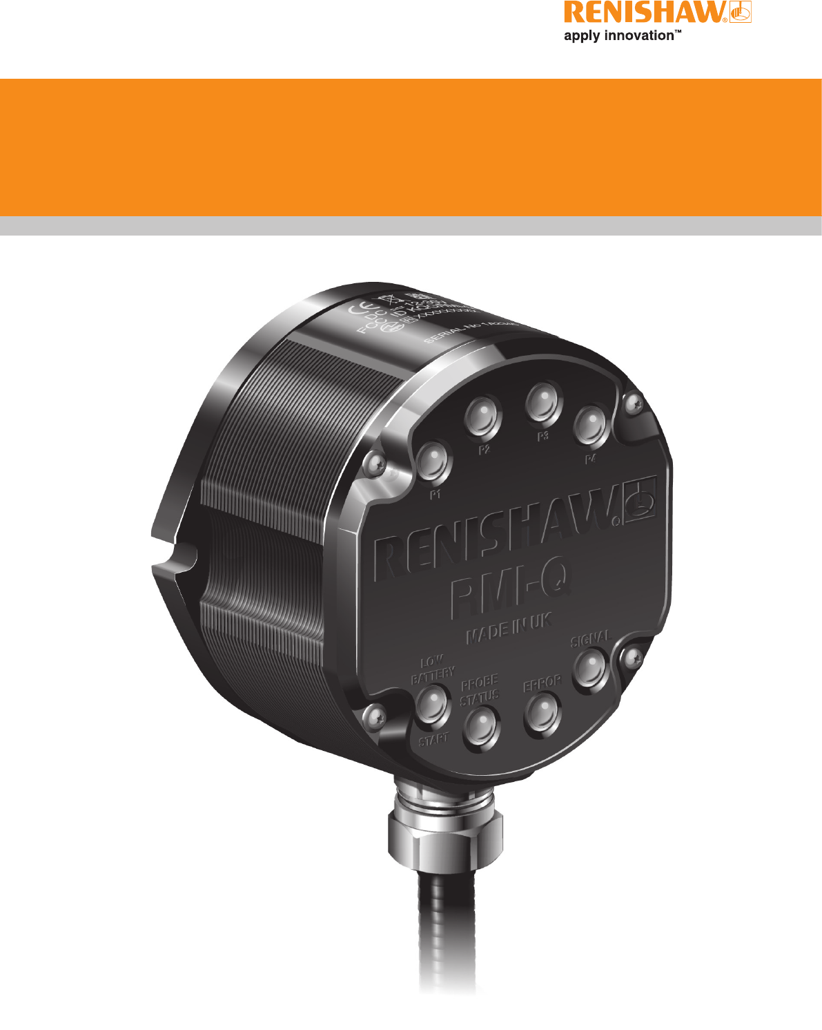
RMI-Q radio machine interface
Installation guide
H-5687-8504-01-A (BETA SITE ONLY)
Renishaw part no: H-5687-8504-01-A
First issued: BETA SITE ONLY
© 2012 Renishaw plc. All rights reserved.
This document may not be copied or reproduced
in whole or in part, or transferred to any other
media or language, by any means, without the
prior written permission of Renishaw plc.
The publication of material within this document
does not imply freedom from the patent rights of
Renishaw plc.

i
Contents
Contents
Before you begin ....................................................................................................1.1
Before you begin ............................................................1.1
Disclaimer ..............................................................1.1
Trademarks .............................................................1.1
Warranty ................................................................1.1
Changes to equipment .....................................................1.1
CNC machines ...........................................................1.1
Care of the RMI-Q ........................................................1.1
RMP probe family ......................................................... 1.2
Patents .................................................................1.2
EC declaration of conformity ...................................................1.3
WEEE directive .............................................................1.3
FCC information to the user (USA only) ..........................................1.3
Radio approval .............................................................1.4
Radio equipment - Canadian warning statements ................................1.4
Radio approvals ..........................................................1.4
Safety ....................................................................1.5
RMI-Q basics ........................................................................................................... 2.1
Introduction ................................................................2.1
Power supply ...............................................................2.1
Input voltage ripple ........................................................2.1
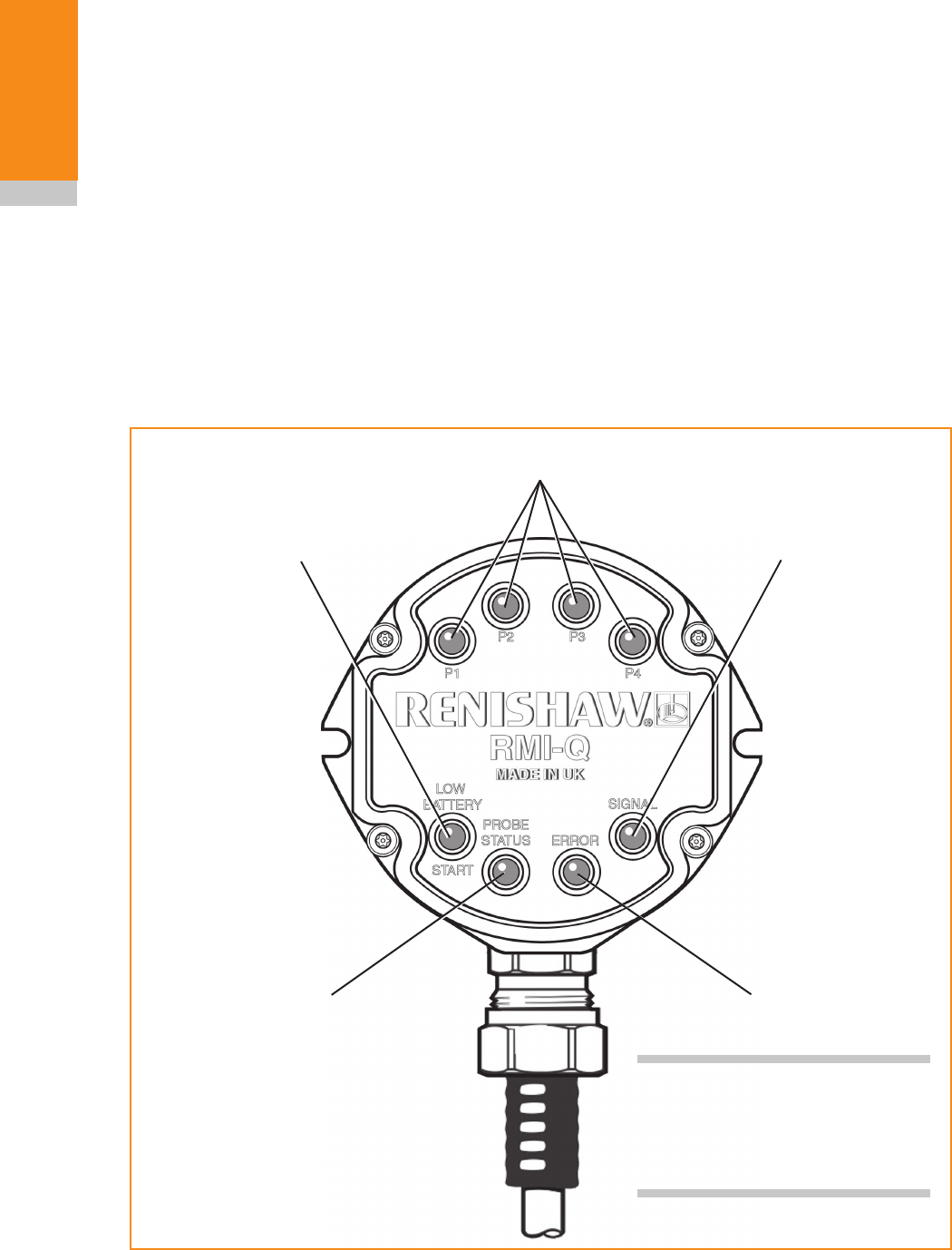
RMI-Q visual diagnostics ......................................................2.2
P1, P2, P3, P4 SYSTEM STATUS LEDs .......................................2.3
LOW BATTERY / START LED ...............................................2.3
PROBE STATUS LED .....................................................2.3
ERROR LED ............................................................2.3
SIGNAL LED ............................................................2.3

RMI-Q installation guide
ii
Contents
RMI-Q inputs ...............................................................2.4
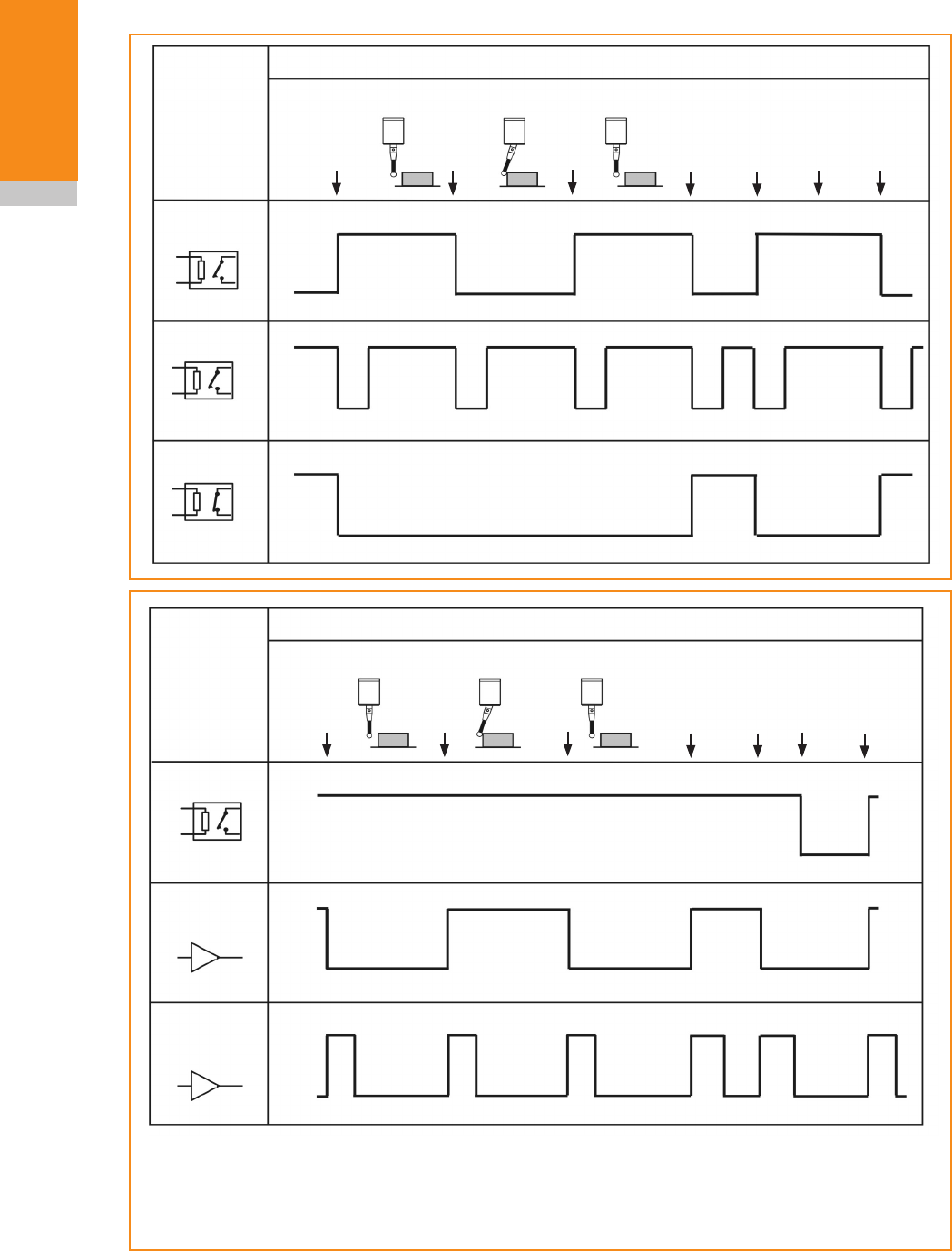
RMI-Q output waveforms ......................................................2.6
RMI-Q seated start option .....................................................2.7
Switches SW1 and SW2 ......................................................2.8
Switch SW1 output configuration .............................................2.8
Switch SW2 output configuration .............................................2.9
Remote external audible output ...............................................2.11
RMI-Q dimensions ..........................................................2.12
RMI-Q specification .........................................................2.13
System installation ................................................................................................. 3.1
Mounting bracket (optional) ....................................................3.1
Wiring diagram (with output groupings shown) .....................................3.2
RMP - RMI-Q partnership .....................................................3.3
To partner the RMP with the RMI-Q ...........................................3.3
To partner up to four RMPs with the RMI-Q without ReniKey .......................3.4
Partnering RMPs using ReniKey (Recommended) ...............................3.5
Removing the RMP from the RMI-Q ..........................................3.5
Changing RMP position ...................................................3.5
RMI-Q cable ...............................................................3.6
Cable sealing ............................................................3.6
Fitting flexible conduit ......................................................3.6
Screw torque values .........................................................3.7
Maintenance ............................................................................................................ 4.1
RMI-Q cover ...............................................................4.1
Removing the RMI-Q cover .................................................4.1
Replacing the RMI-Q cover .................................................4.2
Side exit to rear exit cable conversion ............................................4.2
Fault finding ............................................................................................................ 6.1
Parts list .................................................................................................................. 7.1

1.1
Before you begin
Disclaimer
RENISHAW HAS MADE CONSIDERABLE
EFFORTS TO ENSURE THE CONTENT OF THIS
DOCUMENT IS CORRECT AT THE DATE OF
PUBLICATION BUT MAKES NO WARRANTIES
OR REPRESENTATIONS REGARDING
THE CONTENT. RENISHAW EXCLUDES
LIABILITY, HOWSOEVER ARISING, FOR ANY
INACCURACIES IN THIS DOCUMENT.
Trademarks
RENISHAW and the probe symbol used in the
RENISHAW logo are registered trade marks of
Renishaw plc in the United Kingdom and other
countries.
apply innovation and names and designations
of other Renishaw products and technologies are
trade marks of Renishaw plc or its subsidiaries.
All other brand names and product names used
in this document are trade names, service marks,
trademarks, or registered trademarks of their
respective owners.
Warranty
Equipment requiring attention under warranty must
be returned to your equipment supplier.
Unless otherwise specifically agreed in writing
between you and Renishaw, if you purchased the
equipment from a Renishaw company, the warranty
provisions contained in Renishaw’s CONDITIONS
OF SALE apply. You should consult these
conditions in order to find out the details of your
warranty, but in summary the main exclusions from
the warranty are if the equipment has been:
• neglected,mishandledorinappropriately
used; or
• modifiedoralteredinanywayexceptwiththe
prior written agreement of Renishaw.
If you purchased the equipment from any other
supplier, you should contact them to find out what
repairs are covered by their warranty.
Changes to equipment
Renishaw reserves the right to change equipment
specifications without notice.
CNC machines
CNC machine tools must always be operated by
fully trained personnel in accordance with the
manufacturer's instructions.
Care of the RMI-Q
Keep system components clean.
Before you begin

RMI-Q installation guide
1.2
Before you begin
RMP probe family
The RMP family of probes currently consists of the
RMP40, RMP40M, RLP40, RMP60, RMP60M and
RMP600. The RTS radio tool setter also forms part
of Renishaw's family of radio transmission probes.
The term RMP used throughout this installation
guide refers to both the probes and the tool setter. CN 100466003
CN 101287958
CN 101482402A
EP 0652413
EP 1576560
EP 1931936
EP 2216761
IN 2004/057552
IN 2007/028964
IN 215787
JP 2009-507240
JP 3126797
JP 4575781
KR 1001244
TW 1333052
US 2011-00002361-A1
US 5279042
US 7665219
US 7821420
Patents
Features of the RMI-Q (and features of similar
products) are the subject of one or more of the
following patents and/or patent applications:

1.3
Before you begin
C
EC declaration of conformity
Renishaw PLC hereby declares that the RMI-Q is
in compliance with the essential requirements and
other relevant provisions of Directive 1999/5/EC.
Contact Renishaw at www.renishaw.com/rmi-q for
the full EC Declaration of Conformity.
WEEE directive
The use of this symbol on Renishaw products
and/or accompanying documentation indicates
that the product should not be mixed with
general household waste upon disposal. It is the
responsibility of the end user to dispose of this
product at a designated collection point for waste
electrical and electronic equipment (WEEE) to
enable reuse or recycling. Correct disposal of
this product will help to save valuable resources
and prevent potential negative effects on the
environment. For more information, please contact
your local waste disposal service or Renishaw
distributor.
FCC information to the user
(USA only)
47 CFR Section 15.19
The user is cautioned that any changes or
modifications not expressly approved by
Renishaw plc, or authorised representative could
void the user’s authority to operate the equipment.
This device complies with Part 15 of the FCC
rules.
Operation is subject to the following two
conditions:
1. This device may not cause harmful
interference.
2. This device may accept any interference
received, including interference that may
cause undesired operation.
47 CFR Section 15.21
The user is cautioned that any changes or
modifications not expressly approved by
Renishaw plc, or authorised representative could
void the user’s authority to operate the equipment.
47 CFR Section 15.105
This equipment has been tested and found to
comply with the limits for a Class A digital device,
pursuant to Part 15 of the FCC rules. These limits
are designed to provide reasonable protection
against harmful interference when the equipment
is operated in a commercial environment. This
equipment generates, uses, and can radiate
radio frequency energy and, if not installed
and used in accordance with the instruction
manual, may cause harmful interference to radio
communications. Operation of this equipment
in a residential area is likely to cause harmful
interference, in which case you will be required to
correct the interference at your own expense.

RMI-Q installation guide
1.4
Before you begin
Radio approval
Radio equipment - Canadian warning
statements
English
Under Industry Canada regulations, this radio
transmitter may only operate using an antenna of
a type and maximum (or lesser) gain approved for
the transmitter by Industry Canada.
To reduce potential radio interference to other
users, the antenna type and its gain should be so
chosen that the equivalent isotropically radiated
power (e.i.r.p.) is not more than that necessary for
successful communication.
This device complies with Industry Canada
licence-exempt RSS standard(s). Operation is
subject to the following two conditions: (1) this
device may not cause interference, and (2) this
device must accept any interference, including
interference that may cause undesired operation
of the device.
French
Conformément à la réglementation d'Industrie
Canada, le présent émetteur radio peut
fonctionner avec une antenne d'un type et d'un
gain maximal (ou inférieur) approuvé pour
l'émetteur par Industrie Canada.
Dans le but de réduire les risques de brouillage
radioélectrique à l'intention des autres utilisateurs,
il faut choisir le type d'antenne et son gain
de sorte que la puissance isotrope rayonnée
équivalente (p.i.r.e.) ne dépasse pas l'intensité
nécessaire à l'établissement d'une communication
satisfaisante.
Le présent appareil est conforme aux CNR
d'Industrie Canada applicables aux appareils
radio exempts de licence. L'exploitation est
autorisée aux deux conditions suivantes : (1)
l'appareil ne doit pas produire de brouillage,
et (2) l'utilisateur de l'appareil doit accepter
tout brouillage radioélectrique subi, même si le
brouillage est susceptible d'en compromettre le
fonctionnement.
Radio approvals
Europe: TBA
USA: TBA
Canada: TBA
Japan: TBA
China: TBA

1.5
Before you begin
Safety
Information to the user
In all applications involving the use of machine
tools or CMMs, eye protection is recommended.
Information to the machine supplier/
installer
It is the machine supplier's responsibility to ensure
that the user is made aware of any hazards
involved in operation, including those mentioned
in Renishaw product literature, and to ensure
that adequate guards and safety interlocks are
provided.
Under certain circumstances, the probe signal
may falsely indicate a probe seated condition. Do
not rely on probe signals to halt the movement of
the machine.
Information to the equipment installer
All Renishaw equipment is designed to comply
with the relevant EU and FCC regulatory
requirements. It is the responsibility of the
equipment installer to ensure that the following
guidelines are adhered to, in order for the product
to function in accordance with these regulations:
• any interface MUST be installed in a position
away from any potential sources of electrical
noise, i.e. power transformers, servo drives
etc;
• all ground connections should be connected
to the machine 'star point' (the 'star point'
is a single point return for all equipment
ground and screen cables). This is very
important and failure to adhere to this
can cause a potential difference between
grounds;
• all screens must be connected as outlined in
the user instructions;
• cables must not be routed alongside high
current sources, i.e. motor power supply
cables etc, or be near high speed data lines;
• cable lengths should always be kept to a
minimum.
Equipment operation
If this equipment is used in a manner not specified
by the manufacturer, the protection provided by
the equipment may be impaired.

RMI-Q installation guide
1.6
Before you begin
This page left intentionally blank
2.12.1
Introduction
CNC machine tools which are using Renishaw
spindle probes with radio signal transmission
for workpiece inspection, or tool setters with
radio signal transmission, require a Renishaw
radio machine interface (such as the RMI-Q)
for signal transmission. The RMI-Q, which acts
as a combined radio transceiver and machine
interface, converts signals from the RMP into
voltage-free solid state relay (SSR) and driven
outputs for transmission to the CNC machine
controller.
The RMI-Q is designed to be mounted within
the machine’s working envelope.
Application of the RMI-Q enables individual
radio turn on and subsequent operation of up to
four separate 2nd generation RMPs, permitting
numerous combinations of radio inspection
probes and/or radio tool setters to be used on the
same machine tool.
RTS, and other 2nd generation RMPs, are easily
identified by a 'Q' marking. 1st generation RMPs,
which do not have the 'Q' marking, may also
be used with the RMI-Q. However, in machine
tool applications where more than one RMP
is required, it is recommended that only 2nd
generation RMPs are used. Should there be a
requirement to use a 1st generation RMP with the
RMI-Q, it is necessary that any additional probes
are 'Q' marked 2nd generation RMPs
RMI-Q basics
Optimum communication performance between
the RMI-Q and the RMP is achieved when the
RMI-Q is aligned towards the RMP in operation.
Other alignments are permissible with negligible
reduction in communication performance.
However, alignment of the RMI-Q away from the
RMP should be avoided as this may result in
reduced communication performance.
CAUTION RMI-Q operation of up to four
separate RMPs is different to 'multiple probe
mode' which is a function of the RMP that enables
individual application of multiple probes but does
not use radio turn on.
Power supply
The RMI-Q can draw its supply from the CNC
machine tool's 12 Vdc to 30 Vdc supply and
present a peak load of up to 250 mA during turn
on (typically 100 mA from 24 V).
Input voltage ripple
The input voltage ripple must not cause the
voltage to fall below 12 V or rise above 30 V.
!
RMI-Q installation guide
2.2
RMI-Q basics
RMI-Q visual diagnostics
A visual indication of system status is provided
by LEDs. Status is continuously updated and
indication is provided for:
• P1, P2, P3, P4 SYSTEM STATUS;
• LOW BATTERY/START;
• PROBE STATUS;
• SIGNAL CONDITION;
• ERROR;
SIGNAL LED
P1, P2, P3, P4 SYSTEM STATUS LEDs
LOW BATTERY / START LED
ERROR LED
PROBE STATUS LED
NOTES:
KEEP THE FRONT COVER CLEAN.
All four lower LEDs flashing
indicates a wiring fault or output
over-current.

2.3
RMI-Q basics
P1, P2, P3, P4 SYSTEM STATUS LEDs
Off - Probe number empty.
Yellow - Probe number full, in standby.
Green - Probe number full, operating.
Red - Probe number full, 0.5 s
compatibility error.
Yellow/off - Flashing: Selection error.
Green/yellow - Flashing: Acquisition/clearing
pending, full.
Green/off - Flashing: Acquisition pending,
empty.
Red/yellow - Flashing: Acquisition complete,
probe full.
Red/off - Flashing: Clearing complete,
probe empty.
LOW BATTERY / START LED
Off - Battery is OK and no M code
start/stop in progress.
Red - Battery is low.
Green - M code start/stop in progress.
Yellow - Battery low and M code
start/stop in progress.
Red/off - Flashing: RMI-Q has an
overcurrent condition.
PROBE STATUS LED
Red - Probe triggered.
Green - Probe seated.
Red/off - Flashing: RMI-Q has an
overcurrent condition.
ERROR LED
Off - No error.
Red - Error, other outputs may be
incorrect.
Red/off - Flashing: RMI-Q has an
overcurrent condition.
SIGNAL LED
Off - No probes operating.
Green - Good communications.
Green - yellow - Good communications.
Red - Poor communications, radio link
may fail.
Red/off - Flashing: RMI-Q has an
overcurrent condition.
NOTES:
The 'PROBE STATUS' LED is always illuminated
when power is present at the RMI-Q (as the
RMI-Q does not incorporate a separate ‘power
present’ indicator).
All LEDs report the status of the partner RMP. If
there is no partner in range, or the partner is off,
then the 'PROBE STATUS' and 'ERROR' LEDs
will illuminate red. The 'LOW BATTERY/START'
and 'SIGNAL' LEDs will be off.
When the RMI-Q is powered on it will enter
the acquire partner mode. This is indicated by
a flashing green 'SIGNAL' LED (no change in
outputs). After ~60 seconds it will switch to its
normal mode listening for its partner.
The conditions shown by the 'LOW BATTERY/
START', 'PROBE STATUS' and 'ERROR' LEDs
are the same as those present on the electrical
signal outputs.

RMI-Q installation guide
2.4
RMI-Q basics
RMI-Q inputs
Machine start inputs (P1, P2, P3, P4):
'Machine start' inputs are configurable as a level
or pulsed signal.
Level 10 to 30 V (2.4 mA at 24 V)
When input is active, probe is
switched on.
Pulsed 12 to 30 V (10 mA at 24 V)
Probe toggles from being switched on/
off. The minimum pulse width is 10 ms.
P1 machine start wires (white +ve and brown -ve).
P2 machine start wires (pink +ve and brown -ve).
P3 machine start wires
(white/red +ve and brown -ve).
P4 machine start wires
(white/blue +ve and brown -ve).
RMI-Q outputs
There are five outputs:
• Probe status 1 (SSR).
• Probe status 2a
(5 V isolated driven skip).
• Probe status 2b
(driven at power supply voltage).
• Error (SSR).
• Low battery (SSR).
All outputs can be inverted by using switches SW1
and SW2 - see page 2.8 'Switches SW1 and
SW2'.
Probe status 1, Error, Low battery (SSR):
• ‘On’ resistance = 50 ohm max.
• Load voltage = 40 V max.
• Load current = 100 mA max.
Probe status 2a (5 V isolated driven skip):
• Load current = 50 mA max.
Output voltages
• Sourcing = 4.2 V min at 10 mA.
= 2.2 V min at 50 mA.
• Sinking = 0.4 V max at 10 mA.
= 1.3 V max at 50 mA.
Probe status 2b (driven at power supply
voltage):
• Load current = 50 mA max.
Output voltages
• Sourcing voltage drop
= 2.6 V max at 10 mA.
= 3.5 V max at 50 mA.
• Sinking voltage drop
= 2.0 V max at 10 mA.
= 2.9 V max at 50 mA.
The 'LOW BATTERY/START', 'PROBE STATUS',
'ERROR' and 'SIGNAL' LEDs will start flashing
red when an output overload has occurred. All
outputs will be switched off. If this occurs, turn off
the power supply and remove the source of the
problem. Turning on the power supply will reset
the RMI-Q.

2.5
RMI-Q basics
!
CAUTIONS:
Power supply voltage
Do not exceed 30 V between the black wire and
the screen wire (green/yellow), or the red wire
and screen wire (green/yellow), or the red and
black wires (power supply), as this could result
in permanent damage to the RMI-Q and/or the
customer power supply.
The use of in-line fuses at the machine cabinet
end is recommended to provide protection for the
RMI and cable.
Screen connection
A good connection must be made to machine
ground (star point).
Output stage circuit
Output stage supplies (+ve, –ve) should not be
switched on and off to enable/disable them as this
can cause the over current protection to switch off
the output completely.
Ensure that outputs from the RMI-Q do not
exceed specified current ratings.
RMI-Q installation guide
2.6
RMI-Q basics
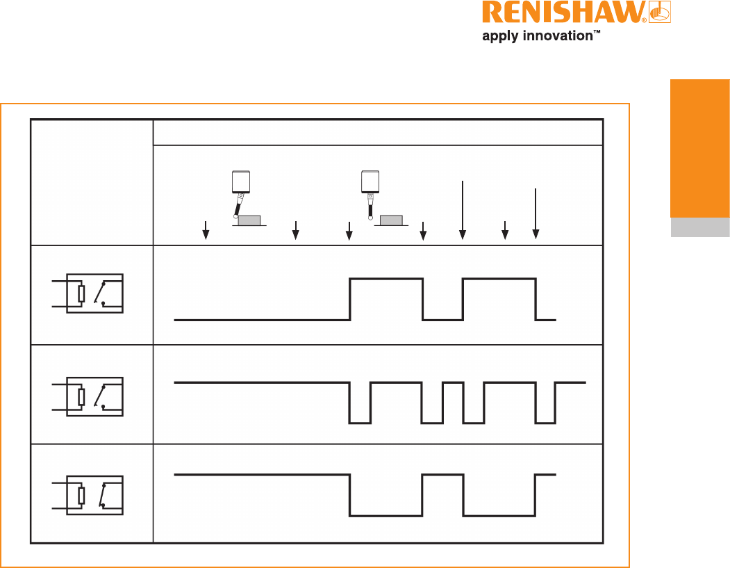
RMI-Q output waveforms
RMI-Q
SSR/driven
output
Probe status 1
(level)
Probe status 1
(pulsed)
Normally open
Normally open
PROBE
SSR open
SSR open
SSR closed
SSR closed
Power
off
Probe
switch
on
Seated
Probe
trigger
Triggered Seated
Probe
reseat
Error
e.g.
low signal
Low
battery
Probe
switch
off
PROBE
RMI-Q
SSR /driven
outputs Probe
switch
on
Seated
Probe
trigger
Triggered Seated
Probe
reseat
Error
clear
Error
e.g.
low signal
Low
battery
Probe
switch
off
Probe status
2a/2b
(level)
Normally low
Output high
SSR open
SSR closed
Error
Normally
closed
Error
clear
Power
off
Low battery
Normally open
SSR open
SSR closed
Output low
Probe status
2a/2b
(pulsed)
Normally low
Output high
Output low
SIGNAL DELAYS
1. Transmission delay Probe trigger to output change of state ≈ 10 ms variation ±10 µs.
(Standard turn on mode exluding filter delay)
2. Start delay Time from initiation of start signal to valid signal transmission = 1 sec max.
NOTE : Pulsed outputs are 40 ms ±1 ms duration.
2.7
RMI-Q basics
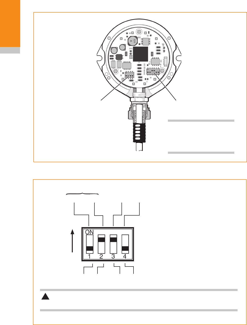
RMI-Q seated start option
RMI-Q
SSR/driven
output
Probe status 1
(level)
Probe status 1
(pulsed)
Normally open
Normally open
PROBE
SSR open
SSR open
SSR closed
SSR closed
Power
off
Probe
switch
on
Probe
trigger
Triggered Seated
Probe
reseat
Error
e.g.
low signal
Low
battery
Probe
switch
off
SSR open
SSR closed
Error
Normally
closed
Error
clear
RMI-Q installation guide
2.8
RMI-Q basics
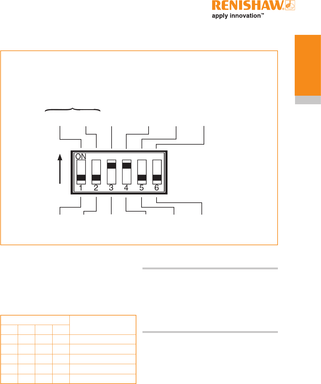
Switches SW1 and SW2
Switch SW1 output configuration
SW1 SW2
NOTE: To gain access to
the switches, remove the
front cover (see Section 4,
'Maintenance').
Factory settings are shown.
Pulsed N/O
PROBE STATUS 1 Low
battery
N/O
Error
N/O
N/CN/C
N/C
Level
ON
CAUTION: Exercise caution when using error or probe SSR in N/O mode as a wiring
fault could cause loss of error condition and therefore could result in a non-failsafe condition.
!
Abbreviations are as follows:
• N/O = Normally Open
• N/C = Normally Closed
2.9
RMI-Q basics
Pulsed Normally
high
PROBE STATUS 2a/2b
Level
Dedicated
start
Seated
start on
Seated
start off
0.5 s
turn on
Standard
turn on
Common
start
Pulsed
Level
MACHINE START
Normally
low
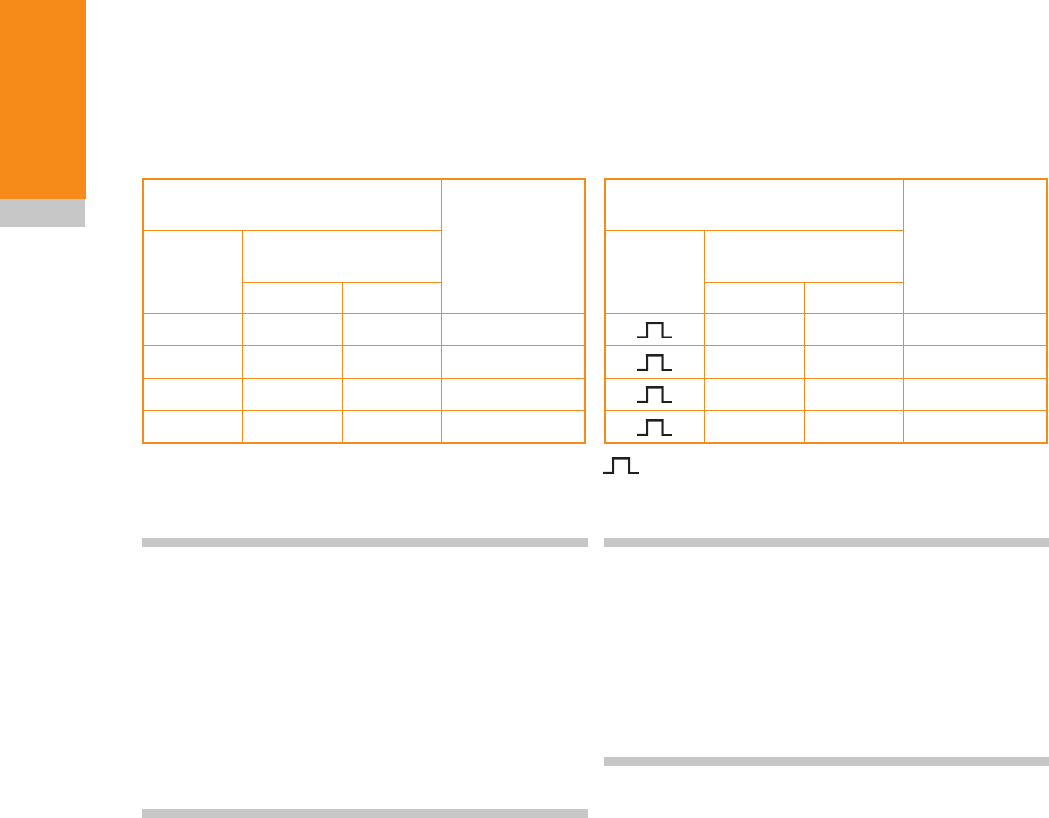
Switch SW2 output configuration
Factory settings are shown.
ON
Dedicated start (level mode)
In dedicated start, a machine start input is
required per probe that is configured for radio turn
on.
Machine start inputs Probe selected
P1 P2 P3 P4
None
QProbe 1 on
QProbe 2 on
QProbe 3 on
QProbe 4 on
Q Machine start input active. Any attempt to turn on more
than one probe simultaneously will result in an error
condition
NOTES :
Level start mode is not compatible with RMPs
configured for radio M code on/time out off.
For RMI compatibility mode, ensure poles 4 and 6
are in the down position and set other poles to the
required configuration.
RMI-Q installation guide
2.10
RMI-Q basics
Common start (level mode)
In common start (level mode), machine start
inputs P2 and P3 are used to select the probe
and machine start input P1 is used to start the
selected probe. All inputs are level.
Machine start inputs
P1, P2 and P3
Probe
selected
Probe
start
P1
Probe selection
inputs
P2 P3
QProbe 1
Q Q Probe 2
Q Q Probe 3
QQQProbe 4
Q Machine start input active.
When P1 is off, all probes are off.
When P1 is active, the selected probe will be on.
NOTES:
Machine start input P4 is not used in common
start.
Any change to the probe selection inputs P2 and
P3 whilst the probe is operating will result in an
error condition.
Level start mode is not compatible with RMPs
configured for radio M code on/time out off.
Common start (pulsed mode)
In common start (pulsed mode), machine start
inputs P2 and P3 are level inputs used to select
the probe. Machine start input P1 is a pulsed input
used to start the selected probe.
Machine start inputs
P1, P2 and P3
Probe
selected
Probe
start
P1
Probe selection
inputs
P2 P3
Probe 1
QProbe 2
QProbe 3
Q Q Probe 4
Machine start input pulsed, so selected probe will
change state.
Q Probe selection inputs are level signals.
NOTES:
Machine start input P4 is not used in common
start.
Only the probe start signal P1 will be pulsed and
will change the probe status between on and off.
The probe selection inputs P2 and P3 will be level.
Seated start on
When seated start on is selected, the RMI-Q will
not drop the error line until the RMP has become
seated. This provides compatibility with controllers
that regard the RMP to be in error if it is started in
a triggered condition.
0.5 second turn on
0.5 second turn on provides compatibility with
controllers that have quicker response times, to
give a reduced probing cycle time. Standard turn
on time is 1 second. These turn on times apply to
radio M code on only.
2.11
RMI-Q basics
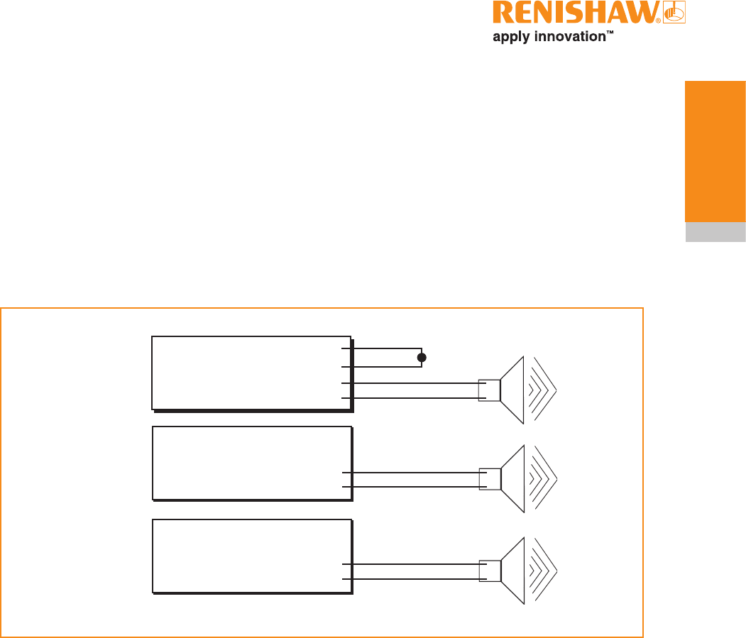
Remote external audible output
Any output (set to pulsed) can be utilised to
operate an external remote audible indicator.
The audible indicator must comply with the output
transistor specification.
i.e. up to 50 mA.
up to 30 V.
Wiring configurations are shown below.
Option 1.
SSR output
Option 2.
Using 5 V output
Option 3.
Using machine
voltage output
RMI-Q
Red
Turquoise
Turquoise / Black
0 V Black
+ve
–ve
Yellow
0 V Grey
5 V isolated
driven probe
status
RMI-Q
Orange
0 V Black
Driven probe
status output at
supply voltage
+ve
–ve
+ve
–ve
RMI-Q
RMI-Q installation guide
2.12
RMI-Q basics
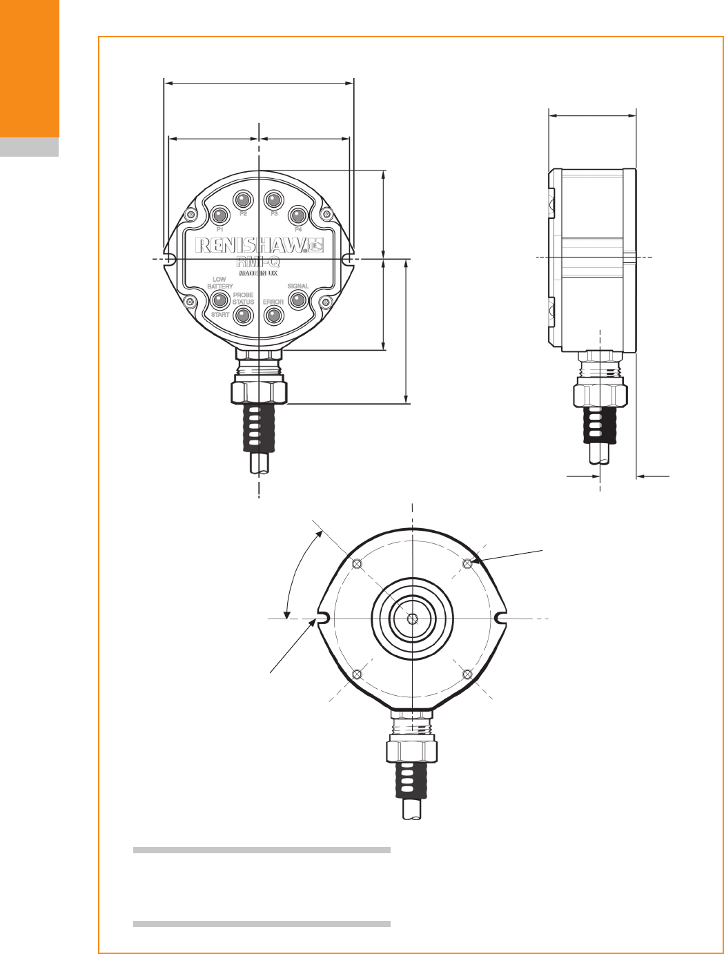
NOTE: When using rear exit cable,
provide a Ø25 mm (Ø1.0 in) hole in the
mounting for the cable to exit.
RMI-Q dimensions
Dimensions given in mm (in)
97 (3.82)
44 (1.73)
45.5 (1.79)
46 (1.81) 46 (1.81)
71.5 (2.81)
47.5 (1.87)
17.5 (0.69)
45° 4 holes
M5 x 13 deep
on 80 P.C.D..
Slot to suit M5 x 16
bolts supplied
(two places)

2.13
RMI-Q basics
Principal application Any machining centre, 5-axis machine, twin spindle machine and
vertical turret lathe.
Dimensions Height
Width
Depth
119 mm (4.68 in)
97 mm (3.82 in)
44 mm (1.73 in)
Weight In box
RMI-Q including 15 m
(49.2 ft) of cable
2,065 g (72.84 oz)
1,625 g (57.32 oz)
Transmission type Frequency hopping spread spectrum (FHSS) radio.
2.400 - 2.4835 GHz
2400 - 2483.5 MHz
Transmission range Up to 15 m (49.2 ft)
Power supply 12 Vdc to 30 Vdc
Cable 8 m (26.2 ft) and 15 m (49.2 ft) standard lengths
Optional 30 m (98.42 ft) and 50 m (164.04 ft) cable assemblies are
also available.
16 core screened cable, each core 18 x 0.1 mm
Mounting Mounting bracket allowing directional setting
Compatible probes Component setting/inspection: RMP40, RMP40M, RMP60, RMP60M
and RMP600
Lathe inspection: RLP40
Tool setting: RTS
Environment IP rating IPX8 (EN/IEC605290)
Storage temperature -25 °C to +70 °C (-13 °F to +158 °F)
Operating temperature +5 °C to +55 °C (+41 °F to +131 °F)
RMI-Q specification

RMI-Q installation guide
2.14
RMI-Q basics
This page left intentionally blank
3.1
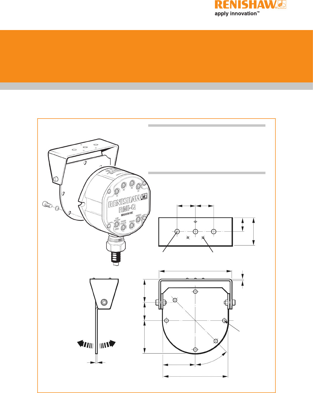
Mounting bracket (optional)
System installation
Dimensions given in mm (in)
25
(0.98)
25
(0.98)
19 (0.75)
38 (1.50)
3 grip protrusions
100.5 (3.95)
2.0 (0.08)
30
(1.18)
25
(0.98)
45
(1.77)
45 (1.77) 45°
90 (3.54)
3 pairs of holes
Ø5.5 (0.20)
permit RMI-Q
mounting in
alternative
orientation
2.0
(0.08)
3 holes Ø6.4 (0.25)
NOTES:
Install RMI-Q with cable exiting from lower side for
good coolant run off.
Mounting bracket cannot be used with an RMI-Q
in rear exit configuration.
RMI-Q installation guide
3.2
System
installation
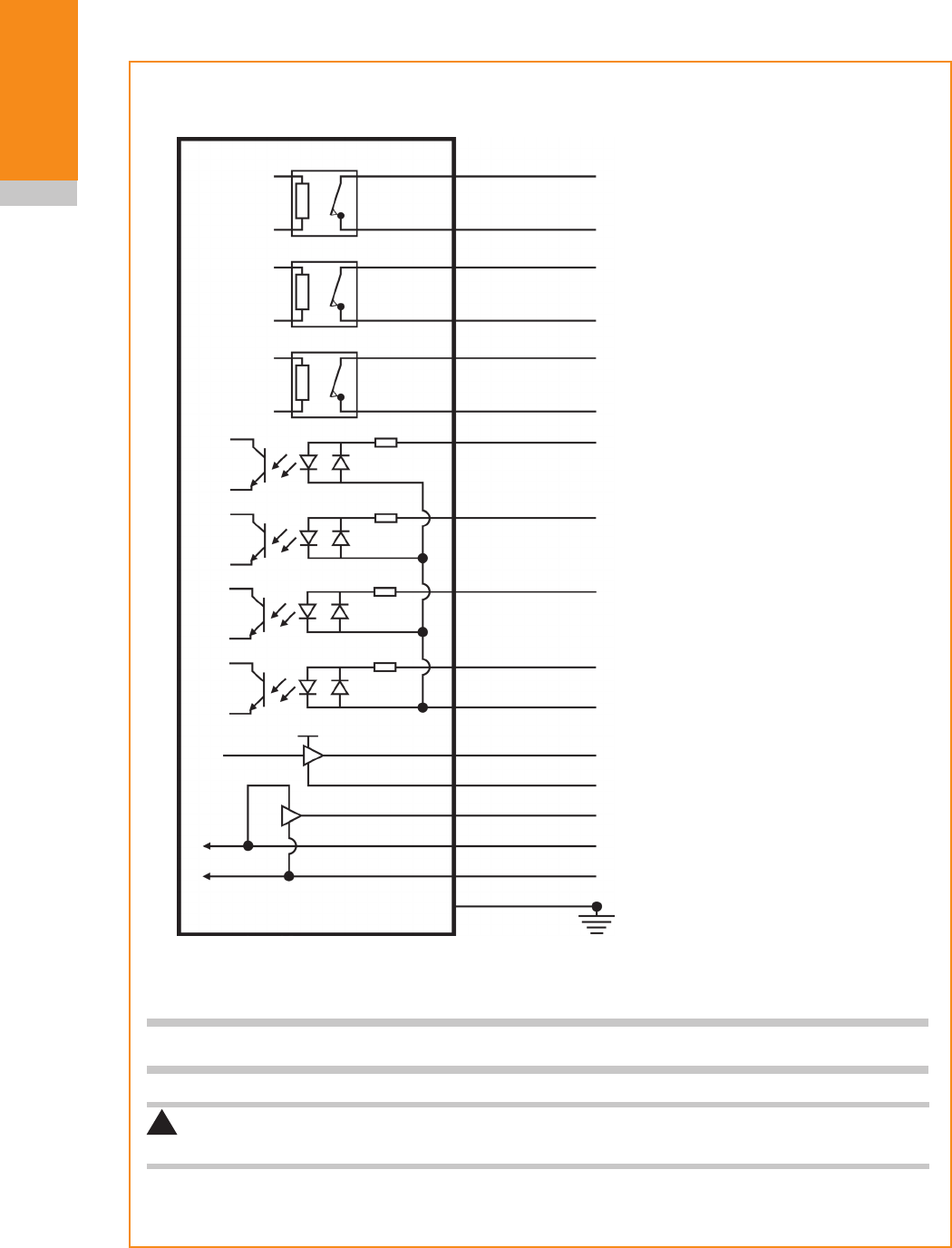
Wiring diagram (with output groupings shown)
12 V to 30 V
Turquoise
Violet
Green
Turquoise/black
Violet/black
Green/black
White
Pink
White/red
Brown
Yellow Signal
Return
See NOTE
Orange
Red
Black
Green
Grey
White/blue
RMI-Q
Machine ground (star point)
Power supply (12 V to 30 V)
Error (SSR)
Probe status 1 (SSR)
Low battery (SSR)
Machine start input [P1]
Machine start input [P2]
Machine start input [P3]
Machine start input [P4]
Machine start common
Probe status 2b
! CAUTION: The power supply 0 V should be terminated at the machine ground (star point).
A negative supply can be used when wired appropriately.
Driver
Screen
Driver Probe status 2a
(5 V isolated driven skip)
5 V
0 V
NOTE: A switch can be added on installation to aid with powering up the RMI-Q when partnering.
}
}
}
}
}

3.3
System
installation
RMP - RMI-Q partnership
The RMP and RMI-Q must be placed into
acquisition mode.
On the RMP, acquisition mode achieved using
Trigger Logic™.
On the RMI-Q, acquisition mode is achieved
either by manually power cycling the RMI-Q, or
via application of ReniKey which is a Renishaw
machine macro cycle.
Trigger Logic™ is a method that allows the user
to view and select all available mode settings
in order to customise a probe to suit a specific
application. Trigger Logic™ is activated by battery
insertion and uses a sequence of stylus deflection
(triggering) to systematically lead the user through
the available choices to allow selection of the
required mode options.
Current probe settings can be reviewed by simply
removing the batteries for a minimum of
5 seconds, and then replacing them to activate
the Trigger Logic™ review sequence.
To partner the RMP with the RMI-Q
Partnering is required during initial system set-up.
Further partnering will be required if either the
RMP or RMI-Q are changed.
Any RMP that is partnered with the RMI-Q, but
then used with another system, will need to
be cleared first from the RMI-Q before being
partnered with the new system. The RMP will also
need to be partnered again should it be brought
back to the RMI-Q.
Partnering will not be lost by reconfiguration of
probe settings or when changing batteries.
NOTE: Partnering will be lost when multiple
probe mode is selected. Multiple probe mode
is a function of the RMP. See the relevant RMP
installation guide (see Section 6, 'Parts list').
Partnering can take place anywhere within the
operating envelope.
1. Use Trigger Logic™ to access RMP
configuration mode.
2. Configure switch-on method (if applicable).
3. Configure switch-off method (if applicable).
4. Configure enhanced trigger filter and auto
reset function (if applicable).
5. Enter acquisition mode menu.
6. Power on the RMI-Q or apply one of the
ReniKey commands. Please refer to the
ReniKey programming manual.
7. Watch the RMI-Q P1 system status LED;
after a couple of seconds the LED will
repeatedly flash on and off green. This is
the start of a 60 second interval in which the
RMI-Q is in acquisition mode.
8. Deflect the stylus < 4 seconds to initiate the
acquisition process.
9. After successful acquisition, the RMI-Q P1
system status LED will change to repeatedly
flashing red and yellow (for 5 seconds)
indicating that acquisition is complete and
Probe 1 is full.
10. Leave RMP for 20 seconds to go into
standby.
11. System is ready to use.
NOTES:
To check that turn on and off settings have not
been accidentally changed, insert batteries to
review current probe settings.
When holding the RMP do NOT wrap a hand, or
anything else, around the glass window.
The system will not function correctly if more than
one partnered RMI-Q is within the transmission
range of the RMP.

RMI-Q installation guide
3.4
System
installation
To partner up to four RMPs with the
RMI-Q without ReniKey
The RMI-Q has four machine start inputs
(P1 - P4) that enable partnering of four radio
probes (see wiring diagram on page 3.2).
The partnering procedure is dependant on the
start method that has been selected. See page
2.9 for start methods.
Partnering with dedicated start (Level mode)
If the RMI-Q is powered with all start inputs
held low, the RMI-Q will complete its start up
procedure and partner the RMP as Probe 1.
When the RMI-Q is powered with a single
machine start input held high, the RMI-Q will
complete its start up procedure and partner the
RMP to the probe number represented by the
selected machine start input.
Level mode
Probe to be partnered Machine start input
P1 P2 P3 P4
Probe 1
Probe 2 Q
Probe 3 Q
Probe 4 Q
The system status LED for the selected probe
number will repeatedly flash on and off green
whilst in acquisition mode.
Partnering with common start
When the RMI-Q is powered, specific machine
start inputs need to be held high when partnering
the RMP to a specific probe number.
Pulsed mode
Probe to be partnered Machine start input
P1 P2 P3
Probe 1
Probe 2 Q
Probe 3 Q
Probe 4 Q Q
Level mode
Probe to be partnered Machine start input
P1 P2 P3
Probe 1
Probe 2 Q Q
Probe 3 Q Q
Probe 4 Q Q Q
NOTES:
Activation of machine start input (P4) is not
required when common start is selected.
To aid partnering, an on/off switch can be fitted
between the machine power supply and the
RMI-Q (red wire). This enables the RMI-Q to
be momentarily powered off and then back on,
for each of the probes being partnered, without
having to power off the machine.

3.5
System
installation
Partnering RMPs using ReniKey
(Recommended)
ReniKey is a Renishaw machine macro cycle. It
enables up to four RMPs to be partnered with
the RMI-Q without the need to power the RMI-Q
off and then back on for each of the probes
being partnered. Please refer to the ReniKey
programming manual for instructions on how
to use ReniKey with your machine's controller.
Alternatively, refer to www.renishaw.com.
Removing the RMP from the RMI-Q
An RMP must be cleared from the RMI-Q when
it is removed from the system. The probe number
is cleared from the RMI-Q by repeating the
partnering procedure whilst the corresponding
machine start input is held high. The RMI-Q
will then display that the probe number was
cleared. Alternatively, the RMP can be cleared via
application of the ReniKey machine macro cycle.
Please refer to the ReniKey programming manual
on how to use ReniKey with your machine's
controller. Alternatively, refer to www.renishaw.
com. ReniKey can also be used to clear all probe
numbers at the same time. If the cleared RMP
is to be used again with the RMI-Q, it must be
re-partnered.
Changing RMP position
If, during partnering with all procedures, the
RMI-Q acquires an RMP that is already stored
under a different probe number, the RMP will be
cleared from its current location and stored under
the new probe number selected for acquisition.
RMI-Q installation guide
3.6
System
installation
RMI-Q cable
Cable termination
A ferrule should be crimped onto each cable wire
for a more positive connection at the terminal box.
Standard cable variants
The RMI-Q standard cables are 8 m (24.6 ft) and
15 m (49.2 ft) long.
Longer cables are available, please see
Section 6, 'Parts list'.
Cable specification
Ø7.6 mm (0.3 in), 16 core screened cable,
each core 18 x 0.1 mm.
NOTE:
Maximum cable length:
30 m (98 ft) at 12 V
50 m (164 ft) at 24 V
Cable sealing
Coolant and dirt are prevented from entering the
RMI-Q by the cable sealing gland. The RMI-Q
cable can be protected against physical damage
by fitting flexible conduit if required.
Recommended flexible conduit is Anamet™
Sealtite HFX (5/16 in) polyurethane.
A conduit kit is available - see Section 6, 'Parts
list'.
CAUTIONS:
Failure to adequately protect the cable can result
in system failure due to either cable damage or
coolant ingress through cores into the RMI-Q.
Failure due to inadequate cable protection will
invalidate the warranty.
When tightening or loosening nut B on the
conduit, ensure that torque is only applied
between A and B.
!
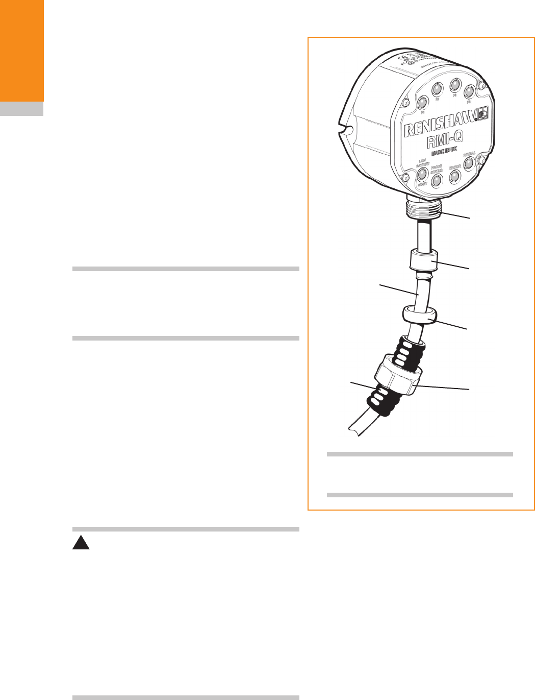
Fitting flexible conduit
Adaptor A
Conduit
termination
piece
Plastic olive
Nut B
Cable
Flexible
conduit
NOTE: Conduit bulkhead fittings require
a clearance hole for an M16 thread.
1. Slide nut B and plastic olive onto the
conduit.
2. Screw conduit termination piece into end of
the conduit.
3. Fit conduit to adaptor A and tighten nut B.
3.7
System
installation
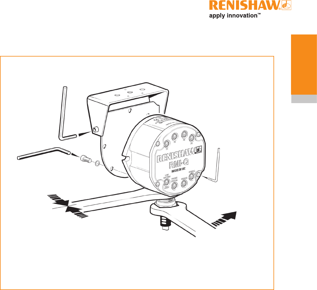
Screw torque values
3 mm AF
2 Nm
(1.47 lbf. ft)
4 mm AF
5.1 Nm
(3.76 lbf. ft)
HOLD
19 mm AF
T10 tamperproof
1.0 Nm (0.74 lbf.ft)
22.0 mm AF (7/8 AF)
Conduit adaptor to RMI-Q body 7 Nm (5.16 lbf.ft)
Rear exit plug (not shown) 5 Nm (3.69 lbf.ft)

RMI-Q installation guide
3.8
System
installation
This page left intentionally blank
4.1
Maintenance
RMI-Q cover
It is not necessary to remove the RMI-Q from the
machine when adjusting the switches or installing
replacement parts. For torque settings see page
3-5 'Screw torque values'.
The front cover may be removed and replaced,
as detailed in this section, if there is a need to
change configuration.
Removing the RMI-Q cover
1. Clean the RMI-Q thoroughly before
servicing to ensure no debris or coolant
enters the unit.
2. Using the T10 tamper proof key (provided),
unscrew (but do not remove) each captive
screw and washer evenly from the cover.
3. When removing the cover, do not twist or
rotate by hand.
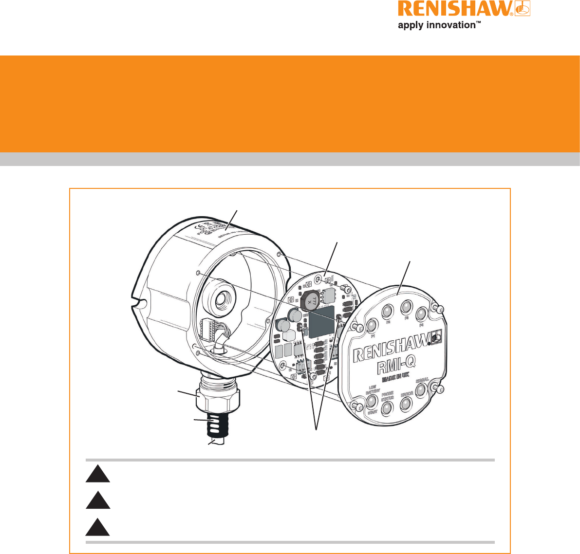
RMI-Q body
PCB
RMI-Q cover
Conduit adaptor
Conduit
Cable Antenna contacts
SAFETY
The main power supply to the machine must be switched off before working on the RMI-Q.
WARNING
Only qualified persons should dismantle this equipment. Faulty workmanship will invalidate the warranty.
KEEP CLEAN
Liquids and solid particles must NOT be allowed to enter the RMI-Q body.
!
!
!

RMI-Q installation guide
4.2
Maintenance
Replacing the RMI-Q cover
1. Remove the O-ring from the cover. Ensure
that the O-ring, the O-ring groove and the
cover sealing face are clean. Lubricate the
O-ring with silicone grease and refit to cover.
2. Ensure that the O-ring seating on the
RMI-Q body is clean, and that there are no
scratch marks which could prevent complete
sealing.
3. Ensure that the antenna contacts are clean.
4. Place cover, complete with O-ring, onto the
RMI-Q body.
NOTE : The O-ring should be lubricated with
silicone grease to prevent damage. Do not allow
grease to contaminate the antenna contacts.
IMPORTANT: Do not overtighten the cover as
distortion could occur.
5. Tighten each captive screw and washer a few
turns at a time, to pull the cover down evenly.
Screw torque is 1.0 Nm (0.74 lbf.ft.).
Side exit to rear exit cable
conversion
1. Remove RMI-Q cover (see page 4.1
'Removing the RMI-Q cover').
2. Remove the three crosshead screws
retaining the PCB. Carefully remove the
PCB and disconnect the cable connection to
the PCB.
3. Unscrew the conduit gland from the RMI-Q
body.
4. Unscrew the rear exit plug and rubber
grommet from the RMI-Q body.
5. Carefully remove the cable assembly and
refit through rear exit hole. Tighten the
conduit gland. For torque settings see page
3.5 'Screw torque values'.
6. Fit the rubber grommet and rear exit plug to
the side exit hole and tighten.
7. Connect the PCB to the cable connector.
Insert the PCB and retain with the three
cross head screws. For torque settings see
page 3.7 'Screw torque values'.
8. Fit the RMI-Q cover (see page 4.2
'Replacing the RMI-Q cover').
CAUTION Conversion from side exit cable
to rear exit cable must only be undertaken by
qualified personnel. Failure to do so will invalidate
the warranty.
!
5.1
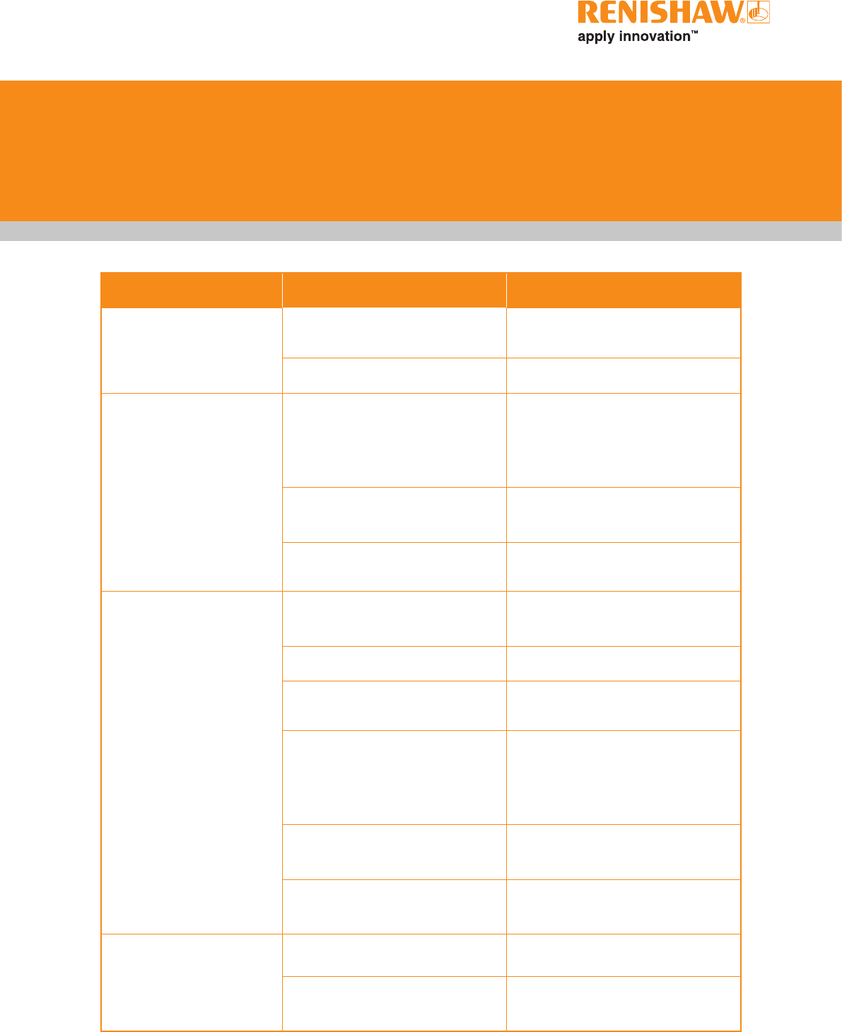
Symptom Cause Action
No LEDs lit on RMI-Q. Overvoltage, undervoltage or no
power.
Check voltage supply.
Damaged cable Check wiring
RMI-Q status LEDs do
not correspond to RMP
status LEDs.
Radio link failure - RMP out of
RMI-Q range.
Check position of RMI-Q, refer
to the operating envelope in the
relevant RMP installation guide
(see Section 6, 'Parts list').
RMP has been enclosed /
shielded by metal.
Review installation.
RMP and RMI-Q are not
partnered.
Partner RMP and RMI-Q.
RMI-Q error LED
illuminated (refer to
page 2.3).
RMP and RMI-Q are not
partnered.
Partner RMP and RMI-Q.
Dead RMP batteries. Change RMP batteries.
Probe not switched on. Check configuration and alter as
required.
Probe out of range. Check position of RMI-Q, refer
to the operating envelope in the
relevant RMP installation guide
(see Section 6, 'Parts list').
Probe selection error. Verify that one RMP is working
and is correctly selected.
RMP is not compatible with 0.5
second turn on.
Change turn on time to 1 second.
All RMI-Q LEDs flashing. Wiring fault. Check wiring.
Output overcurrent. Check wiring, turn power to RMI-Q
off and on again to reset.
Fault finding

RMI-Q installation guide
5.2
Fault-finding
Symptom Cause Action
RMI-Q low battery LED
lit.
Low RMP batteries. Change RMP batteries soon.
Reduced range. Local radio interference. Identify and remove.
RMP has been enclosed /
shielded by metal.
Review installation.
RMI-Q System Status
LED is continually lit
red.
RMP is not compatible for 0.5
second turn on.
Change RMI-Q configuration to
standard turn on.
Use an RMP with a 'Q' marking.
Probe will not turn off. Time out off used with level start
option.
Review system setup.
6.1
Type Part number Description
RMI-Q kit A-5687-0049 RMI-Q with 8 m (26.2 ft) cable, tool kit, quick-start guide and radio
approval label.
RMI-Q kit A-5687-0050 RMI-Q with 15 m (49.2 ft) cable, tool kit, quick-start guide and radio
approval label.
Mounting bracket A-2033-0830 Mounting bracket.
Conduit kit A-4113-0306 Conduit kit with 1 m (3.28 ft) of polyurethane conduit and bulkhead
connector (M16 thread).
Cover assembly A-5687-0305 Cover/antenna assembly: including cover screws, torx key and O-ring.
Cable assembly A-5687-0306 Cable assembly 8 m (26.2 ft) long.
Cable assembly A-5687-0302 Cable assembly 15 m (49.2 ft) long.
Cable assembly A-5687-0303 Cable assembly 30 m (98.4 ft) long.
Cable assembly A-5687-0304 Cable assembly 50 m (164 ft) long.
Tool kit A-4113-0300 Comprising: 1 x T10 tamperproof key, 1 x 4 mm hex key,14 x ferrules,
4 x M5 screw, 2 x M5 nut, 4 x M5 washer, 1 x O-ring (Ø34.5 x 3 mm).
RMI-Q support
software
A-5687-???? CD comprising: ReniKey machine macro cycles with programming
manual and macro software for multiple RTS.
Publications. These can be downloaded from our web site at www.renishaw.com
RMI-Q A-5687-8500 Quick-start guide: for rapid set-up of the RMI-Q radio machine
interface, includes CD with installation guides.
RMP60 A-4113-8501 Quick-start guide: for rapid set-up of the RMP60 probe, includes CD
with installation guides.
RMP600 A-5312-8500 Quick-start guide: for rapid set-up of the RMP600 probe, includes CD
with installation guides.
RMP40 A-5480-8500 Quick-start guide: for rapid set-up of the RMP40 probe, includes CD
with installation guides.
RLP40 A-5627-8500 Quick-start guide: for rapid set-up of the RLP40 probe, includes CD
with installation guides.
RTS A-5646-8500 Quick-start guide: for rapid set-up of the RTS probe, includes CD with
installation guides.
Styli H-1000-3200 Technical specification: Styli and accessories.
Software features H-2000-2289 Data sheet: Probe software for machine tools – illustrated features.
Software list H-2000-2298 Data sheet: Probe software for machine tools – list of programs.
Parts list
NOTE: The serial number of each RMI-Q is found on the top of the housing.

Renishaw plc
New Mills, Wotton-under-Edge,
Gloucestershire, GL12 8JR
United Kingdom
T +44 (0)1453 524524
F +44 (0)1453 524901
E uk@renishaw.com
www.renishaw.com
For worldwide contact details,
please visit our main website at
www.renishaw.com/contact
*H-5687-8504-01*
© 2012 Renishaw plc Issued (BETA SITE ONLY) Part no. H-5687-8504-01-A