Renishaw plc RMIV2 Interface for Sensor Machine Tools User Manual H 2000 5220 02 A RMI UG E cover for web
Renishaw plc Interface for Sensor Machine Tools H 2000 5220 02 A RMI UG E cover for web
USER MANUEL

Installation and user’s guide
H-2000-5220-05-A
RMI - radio machine interface
2003 - 2006 Renishaw plc.
All rights reserved.
This document may not be copied or
reproduced in whole or in part, or
transferred to any other media or language,
by any means, without the prior written
permission of Renishaw.
The publication of material within this
document does not imply freedom from
the patent rights of Renishaw plc.
Renishaw part no: H-2000-5220-05-A
Issued: 07.06
Disclaimer
Considerable effort has been made to ensure
that the contents of this document are free
from inaccuracies and omissions. However,
Renishaw makes no warranties with respect
to the contents of this document and specifically
disclaims any implied warranties. Renishaw
reserves the right to make changes to this
document and to the product described herein
without obligation to notify any person of such
changes.
Trademarks
RENISHAW® and the probe emblem used in
the RENISHAW logo are registered trademarks
of Renishaw plc in the UK and other countries.
apply innovation and Trigger Logic are
trademarks of Renishaw plc.
All brand names and product names used in
this document are trade names, service marks,
trademarks, or registered trademarks of their
respective owners.

1
Contents
Contents
EC declaration of conformity ........................... 2
FCC declaration (USA) .................................... 3
Safety ............................................................... 3
Installation and user’s guide ............................ 4
RMI .................................................................. 5
Mounting bracket ............................................. 6
RMI visual diagnostics .................................... 7
RMI outputs ..................................................... 9
RMI output waveforms ................................... 12
Switches SW1, SW2 and start input ............. 14
Wiring diagram............................................... 16
RMP60-RMI partnership ................................ 17
Remote external audible output .................... 19
RMI cable ....................................................... 20
RMI cable sealing .......................................... 21
Fitting flexible conduit .................................... 21
RMI cover ...................................................... 22
Side exit to rear exit cable conversion .......... 24
Screw torque values ...................................... 25
Fault finding ................................................... 26
Parts list ......................................................... 28

2
EC DECLARATION OF CONFORMITY
Renishaw plc declares that the product:-
Name: RMI
Description: Radio machine interface
has been manufactured in conformity with the following standard:
BS EN 61326:1998/ Electrical equipment for measurement,
control and laboratory use - EMC requirements.
Immunity to annex A - industrial locations.
Emissions to class A - (non-domestic) limits.
and that it complies with the requirements of directive (as amended):
89/336/EEC Electromagnetic compatibility
The above information is summarised from the full EC declaration
of conformity. A copy is available from Renishaw on request.
Radio approvals
Brazil:
Canada: IC: 3928A-RMI
Europe: CE 0536!
Japan: 004NYCA0042
USA: FCC ID KQGRMI
Australia China Israel New Zealand Russia Switzerland

3
FCC DECLARATION (USA)
FCC Section 15.19
This device complies with Part 15 of the FCC rules.
Operation is subject to the following two conditions:
1. This device may not cause harmful interference.
2. This device may accept any interference
received, including interference that may cause
undesired operation.
FCC Section 15.105
This equipment has been tested and found to
comply with the limits for a Class A digital device,
pursuant to Part 15 of the FCC rules. These limits
are designed to provide reasonable protection
against harmful interference when the equipment is
operated in a commercial environment.
This equipment generates, uses , and can radiate
radio frequency energy and, if not installed and
used in accordance with the instruction manual, may
cause harmful interference to radio communications.
Operation of this equipment in a residential area is
likely to cause harmful interference, in which case
you will be required to correct the interference at
your own expense.
FCC Section 15.21
The user is cautioned that any changes or
modifications not expressly approved by Renishaw
plc, or authorised representative could void the
user’s authority to operate the equipment.
SAFETY
Information for the user
Beware of unexpected movement. The user
should remain outside of the full working
envelope of probe head/extension/probe
combinations.
Handle and dispose of batteries in according to
the manufacturers recommendations. Use only
the recommended batteries. Do not allow the
battery terminals to contact other metallic
objects.
In all applications involving the use of machine
tools or CMMs, eye protection is recommended.
Refer to the machine supplier’s operating
instructions.
Information for the machine supplier
It is the machine supplier’s responsibility to
ensure that the user is made aware of any
hazards involved in operation, including those
mentioned in Renishaw product documentation,
and to ensure that adequate guards and safety
interlocks are provided.
Under certain circumstances the probe signal
may falsely indicate a probe seated condition.
Do not rely on probe signals to stop the
machine’s movement.

4Installation and user’s guide
Installation and user’s guide
Warranty
Equipment requiring attention under warranty
must be returned to your supplier. No claims will
be considered where Renishaw equipment has
been misused, or repairs or adjustments have
been attempted by unauthorised persons.
Care of the RMI
Keep system components clean and treat the
RMI with care.
Do not apply metallic labels to the front of the RMI.
Changes to equipment
Renishaw reserve the right to change specifications
without obligation to change equipment previously
sold.
Weight
RMI including 15 metres (49.2 ft) of cable
= 1,700 g (60 oz).
CNC machine
CNC machine tools must always be operated
by competent persons in accordance with
manufacturers instructions.
Environment
Temperature
The RMI is specified for storage over
–10 °C to 70 °C (14 °F to 158 °F) and
operation over 5 °C to 50 °C (41 °F to 122 °F)
ambient temperature range.
Sealing
The unit is fully sealed to IPX8.
Patent notice
Features of products shown in this guide,
and of related products, are the subject of the
following patents and/or patent applications:
EP 0652413
EP 1576560
JP 3,126,797
US 5,279,042
WO 2004-057552
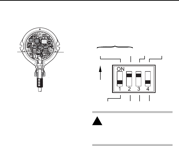
!CAUTION: Only qualified persons should
adjust switches.
5
RMI
The RMI is a combined radio transceiver and
machine interface.
The RMI is designed to be mounted within
the machine's working envelope.
Power supply
The RMI can draw its supply from the CNC
machine 12 V to 30 V d.c. supply and presents
RMI
a peak load of up to 250 mA during turn on
(typically 100 mA from 24 V).
Alternatively, power may be supplied from
a Renishaw PSU3 power supply unit.
Input voltage ripple
The input voltage ripple shall not cause the
voltage to fall below 12 V, or rise above 30 V.
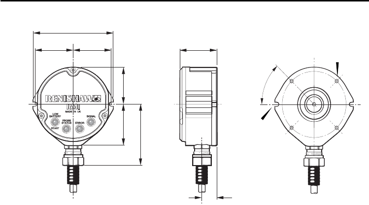
RMI
46 (1.81)
97 (3.82)
46 (1.81)
45 (1.77)
44 (1.73)
50 (1.97)
74 (2.91)
17.5 (0.69)
dimensions mm (in)
45°
4 holes
M5 x 13 deep
on 80 p.c.d.
When using rear exit
cable, provide a
Ø25 (1.0) hole in
mounting for cable exit
Slot to suit M6
bolts supplied
(two places)
6
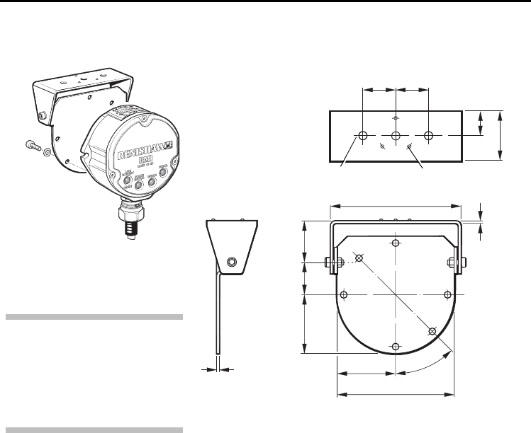
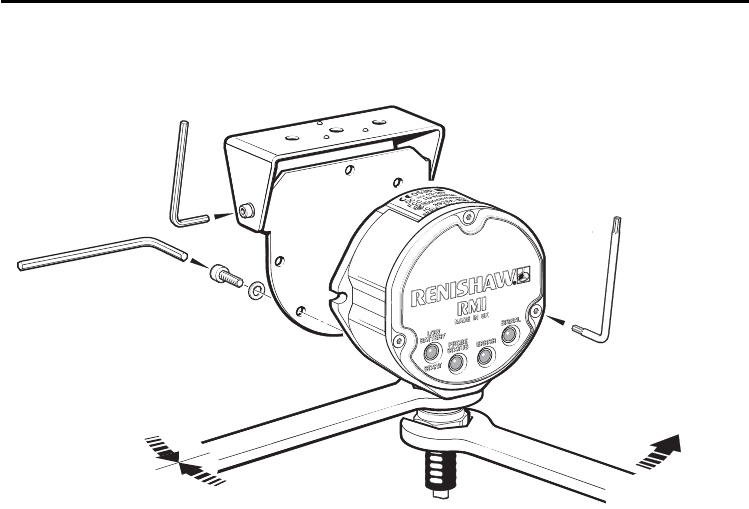
Mounting bracket (optional)
3 holes Ø6.4 (0.25)
25
(0.98)
25
(0.98)
19 (0.75)
38 (1.50)
45
(1.77)
25
(0.98)
30
(1.18)
3 grip protrusions
100.5 (3.95)
90 (3.54)
2.0
(0.08)
6 holes
Ø5.3 (0.20)
2.0
(0.08) Paired holes permit RMI mounting
in alternative orientation.
45 (1.77) 45°
Mounting bracket
dimensions mm (in)
NOTE:
Install RMI with cable exiting from
lower side for good coolant run off.
Mounting bracket cannot be used
with an RMI in rear exit configuration.
7
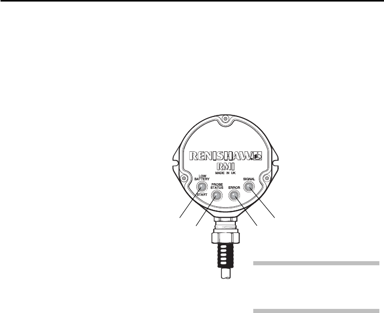
A visual indication of system status is provided by LEDs.
Status is continuously updated and indication is provided for
START, LOW BATTERY, PROBE STATUS, ERROR, SIGNAL STRENGTH
RMI visual diagnostics
RMI visual diagnostics
KEEP THE
FRONT COVER
CLEAN
3
14
LED LIGHT SIGNALS
1. LOW BATTERY / START
Red Battery is low.
Green M code start/stop in
progress.
Yellow Battery low and M code
start/stop in progress.
Off Battery is OK (and no
M code start/stop in
progress).
2. PROBE STATUS
Red Probe triggered or
unknown status.
Green Probe is seated.
2
Note
All LEDs flashing indicates wiring
fault or output over-current

8RMI visual diagnostics
3. ERROR
Red Error, other outputs may
be incorrect.
Off No Error.
4. SIGNAL
Green Excellent communications.
Yellow Good communications.
Red Poor communications,
radio link may fail.
Off No signal detected.
Green/off Flashing: RMI is in
acquisition mode, and can
acquire a partner RMP.
Red/yellow Flashing: RMI has (just)
acquired a new partner RMP.
Notes.
1. The probe status LED will always be
illuminated when power is present.
There is no ‘power present’ LED/light.
2. All the indicators report the status of the
partner RMP60. If there is no partner in
range, or the partner is off then the probe
status and error LEDs will be red and the
other LEDs will be off.
3. When the RMI is powered it will enter the
acquire partner mode which will be indicated
by the flashing green signal LED (no change
in outputs). After a short time (~12 secs) it
will switch to its normal mode listening for
its partner.
4. The conditions shown by the low battery,
probe status and error LEDs are the same
as those present on the electrical signal
outputs.

9
RMI outputs
RMI outputs
There are five outputs:
Probe status 1 (SSR)
Probe status 2a (5 V isolated driven skip)
Probe status 2b (driven at power supply
voltage)
Error (SSR)
Low battery (SSR)
All outputs can be inverted by using switches
SW1 and SW2 - see section Switches SW1,
SW2 and start input.
Probe status 1, Error, Low battery (SSR):
‘On’ resistance = 50 ohms max.
Load voltage = 40 V max.
Load current = 100 mA max.
continued on next page
Probe status 2a (5 V isolated driven skip):
Load current = 50 mA max.
Output voltages
Sourcing = 4.2 V min at 10 mA.
= 2.2 V min at 50 mA.
Sinking = 0.4 V max at 10 mA.
= 1.3 V max at 50 mA.

10
Probe status 2b (driven at power supply voltage):
Load current = 50 mA max.
Output voltages
Sourcing (Voltage supply - Output voltage)
= 2.6 V max at 10 mA.
= 3.5 V max at 50 mA.
Sinking = 2.0 V max at 10 mA.
= 2.9 V max at 50 mA.
The Low Battery, Probe Status, and Error LEDs will
start flashing red when an output overload has occurred.
All outputs will be switched off. If this occurs, turn off the
power supply and remove the source of the problem.
Turning on the power supply will reset the RMI.
RMI outputs

11
RMI outputs
CAUTION:
Power supply voltage
Do not exceed 30 V between the black wire and the screen wire (green/yellow), or the
red wire and screen wire (green/yellow), or the red and black wires (power supply), as
this could result in permanent damage to the RMI and/or the customer power supply.
The use of in-line fuses at the machine cabinet end is recommended to provide
protection for the RMI and cable.
Screen connection
A good connection should be made to machine ground (star point).
Output stage circuit
Output stage supplies (+ve, –ve) should not be switched on and off to enable/disable
them as this can cause the over current protection to switch off the output completely.
Ensure that outputs from the RMI do not exceed specified current ratings.
!
RMI outputs
!
!
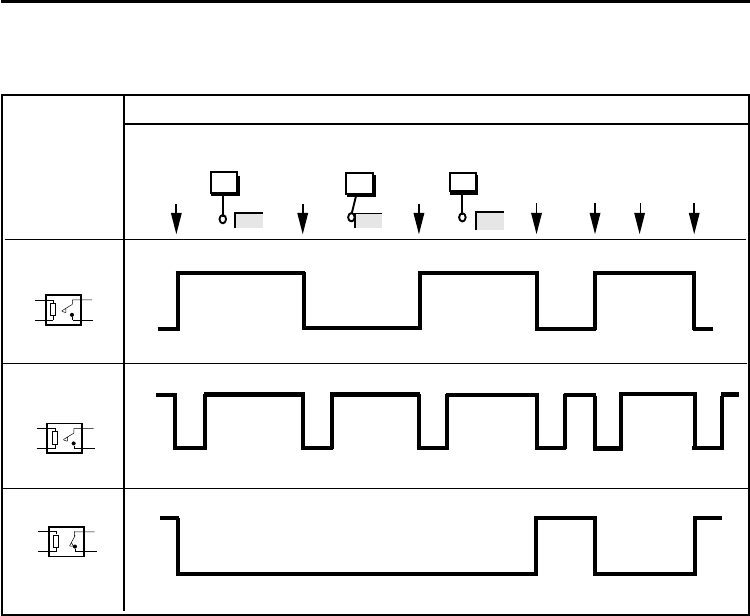
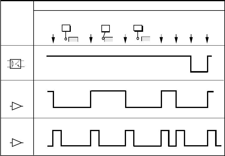
12 RMI output waveforms
Probe
switch
on
Seated
Power
off
Probe
trigger
Triggered
Probe
reseat
Seated Error
e.g.
low signal Error
clear
SSR open
SSR closed
Normally open
Probe
switch
off
Low
battery
PROBE
PROBE STATUS 1
(LEVEL)
RMI
SSR / driven
outputs
Normally open
SSR open
SSR closed
PROBE STATUS 1
(PULSED)
RMI output waveforms
(outputs can be inverted by switches - see section ‘Switches SW1, SW2 and Start Input’)
SSR open
SSR closed
Normally closed
ERROR
13
Probe
switch
on
Seated
Power
off
Probe
trigger
Triggered
Probe
reseat
Seated Error
e.g.
low signal Error
clear
Normally open
SSR open
SSR closed
Probe
switch
off
Low
battery
PROBE
LOW BATTERY
RMI output waveforms
SIGNAL DELAYS
1. Transmission delay Probe trigger to output change of state = 1.3 ms
2. Start delay Time from initiation of start signal to valid signal transmission = 1 sec max.
Note : Pulsed outputs are 40 ms ±1 ms duration.
Output high
Output low
Normally low
PROBE STATUS
2a/2b
(LEVEL)
Normally low
PROBE STATUS
2a/2b
(PULSED)
Output high
Output low
RMI
SSR / driven
outputs
14
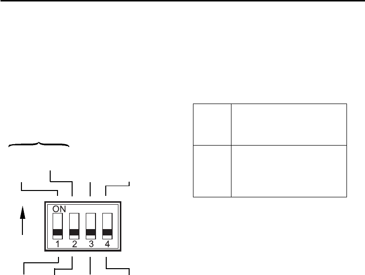
Switches SW1 and SW2
N/C
ON
N/O
N/C
Pulsed N/O
Level
N/O
N/C
PROBE
STATUS 1
LOW
BATTERY
ERROR
Switch SW1 output
configuration
To gain access to the switches,
remove the RMI cover.
SW1 SW2
SWITCH SW1 output configuration
Factory settings shown are for:
A-4113-0050
N/O = Normally Open
N/C = Normally Closed
CAUTION:
Exercise caution when using error SSR in
N/O mode as a wiring fault could cause
loss of error condition and therefore could
result in a non-fail safe condition
!
Switches SW1, SW2 and start input
15
Switch SW2 output
configuration
Level
Pulsed
Normally
high
Pulsed
Normally
low
Not used
ON
Not used
PROBE STATUS 2a/2b
MACHINE START
Level
Machine start
‘Machine start’ is configurable as a level or
pulsed signal.
Level
Pulsed
Machine start wires (white +ve and brown –ve)
10 - 30 V (2.4 mA at 24 V)
When input is active, probe is
switched on
12 - 30 V (10 mA at 24 V)
Probe toggles from being
switched on/off. The minimum
pulse width is 10 ms.
Factory settings shown
are for: A-4113-0050
Start input
Switches SW1, SW2 and start input
16
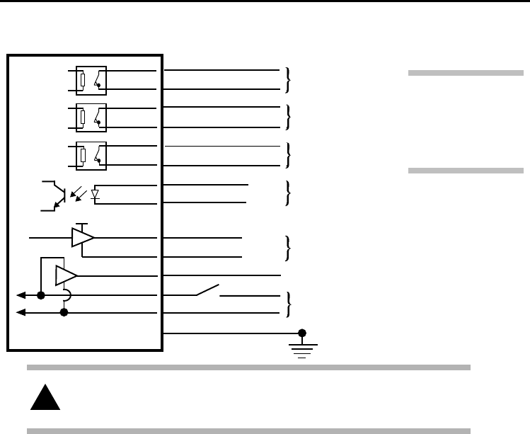
Wiring diagram (with the output groupings shown)
Wiring diagram
12 V to 30 V
0 V
Turquoise
Turquoise/black
Violet
Violet/black
Green
Green/black
White
Brown
Screen
RMI
5 V Driver
Driver
Yellow
Grey
Orange
Red
Black
Green/yellow
Machine ground (star point)
Power supply (12 V to 30 V)
Probe status 1
(SSR)
Low battery
(SSR)
Error
(SSR)
Machine start input
Probe status 2a
(5 V isolated driven skip)
+ve
–ve
Signal
Return
Probe status 2b (driven at power supply voltage)
!CAUTION:
The power supply 0 V should be terminated at the machine ground (star point).
If a negative supply is used then the negative output must be fused.
Note
Switch can be added
on installation to aid
with RMI power up
for partnering.
See Note

17
RMP60-RMI partnership
continued on next page
System setup is achieved using trigger logic
and powering on the RMI.
Trigger logic is a method that allows user
configuration of the options available in the
RMP60. Trigger logic uses a sequence of
RMP60 triggering and battery insertion
followed by further RMP60 triggering.
This leads the user through a series of choices
allowing selection of the required options.
Reviewing of choices can be made by battery
insertion alone. See RMP60 user’s guide for
full details of reviewing probe settings.
To partner an RMP60 and RMI
Partnering is only required during initial system
set-up. Further partnering is only required if
either the RMP60 or RMI is changed.
Partnering cannot be lost by reconfiguration
of probe settings or when changing batteries.
Partnering can take place anywhere within
the operating envelope.
RMP60-RMI partnership
1. Use trigger logic to access RMP60
configuration mode.
2. Configure turn on method (if not configured).
3. Configure turn off method (if not configured).
4. Enter acquisition mode by deflecting stylus.
5. Remain in acquisition mode off by not
releasing stylus. This allows time to get the
RMI ready for partnering.
6. Power on RMI.
7. Watch the RMI signal LED; after a couple
of seconds the LED will repeatedly flash
on and off green. This is the start of a
10 second interval in which the RMI
is in acquisition mode.
8. Release RMP60 stylus and trigger a
couple of times. This causes the RMP60
to go into (and out of) acquisition mode.

18 RMP60-RMI partnership
9. The RMI signal LED will change to
repeatedly flashing red and yellow
(for the remainder of the 10 second
interval) indicating a successful
partnering.
10. Leave RMP60 for 20 seconds to go into
standby.
11. System is ready to use.
Note
To check that turn on and off settings have not
accidentally been changed insert batteries to
review current probe settings.
Note
When holding the RMP60 do NOT wrap a hand,
or anything else, around the glass window.
Note
When the RMP60 and RMI become partners
the RMI records the RMP60 serial number.
It is not possible for an RMI to be partnered
with more than one standard RMP60.
It is possible for an RMP60 to be partnered
with more than one RMI, but the system will
not function correctly.
19
The audible indicator must comply with
the output transistor specification.
i.e. up to 50 mA.
up to 30 V.
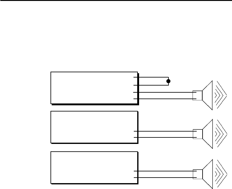
Remote external audible output
Any output (set to pulsed) can be utilised to
operate an external remote audible indicator.
Wiring configurations are shown below.
Remote external audible output
Option 1.
SSR output
Option 2.
Using 5 V output
Option 3.
Using machine
voltage output
RMI
Red
Turquoise
Turquoise / Black
0 V Black
+ve
–ve
Yellow
0 V Grey
5 V isolated
driven probe
status
RMI
Orange
0 V Black
Driven probe status
output at supply
voltage
+ve
–ve
+ve
–ve
RMI

20
Cable termination
A ferrule should be crimped onto each cable
core for more positive connection at the terminal
box.
NOTE:
Maximum cable length:
30 m (98 ft) at 12 V
50 m (164 ft) at 24 V
Standard cable
The RMI standard cable is 15 m (49.2 ft) long,
longer cables are available - see Parts list.
Cable specification:
Ø7,5 mm (0.29 in), 13 core screened cable,
each core 18 x 0,1 mm.
RMI cable
RMI cable
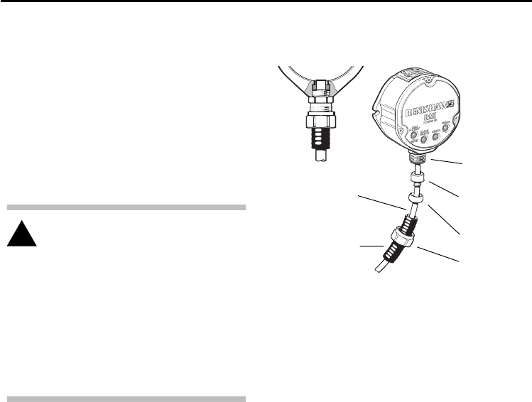
21RMI cable sealing and fitting flexible conduit
Cable
Adaptor A
Conduit
termination
piece
Plastic
olive
Nut B
Conduit bulkhead fittings require a
clearance hole for an M16 thread
CAUTION:
Failure to adequately protect the cable
can result in system failure due to
either cable damage or coolant ingress
through cores into the RMI.
Failure due to inadequate cable
protection will invalidate the warranty.
When tightening or loosening nut B
onto conduit ensure that torque is only
applied between A and B.
Coolant and dirt are prevented from entering
the RMI by the cable sealing gland. The cable
can be protected against physical damage by
fitting flexible conduit if required.
Recommended flexible conduit is AnametTM
Sealtite HFX (5/16 in) polyurethane.
A conduit kit is available - see Parts list.
RMI cable sealing Fitting flexible conduit
1. Slide nut B and plastic olive onto conduit.
2. Screw conduit termination piece into end of
conduit.
3. Fit conduit to adaptor A and tighten nut B.
!Flexible
conduit

22
Replacing the RMI cover
1. Before replacing the cover, check for any
damage to screws or scratch marks
which could prevent sealing.
2. Ensure that the 'O' ring seating on the RMI
body is clean, and there are no scratch
marks which could prevent complete
sealing.
3 Ensure that the cover, antenna contacts
and 'O' ring are clean.
4. Place cover complete with 'O' ring
onto the RMI body.
Note :
The 'O' ring should be lubricated with
silicone grease to prevent nicking.
Do not get any grease on the antenna
contacts.
5. Tighten each captive screw a few turns at
a time, to pull the cover down evenly.
Screw torque is 1,4 Nm (1.03 lbf.ft).
It is not necessary to remove the RMI from
the machine when adjusting the switches or
installing new parts. For torque settings see
Screw torque values.
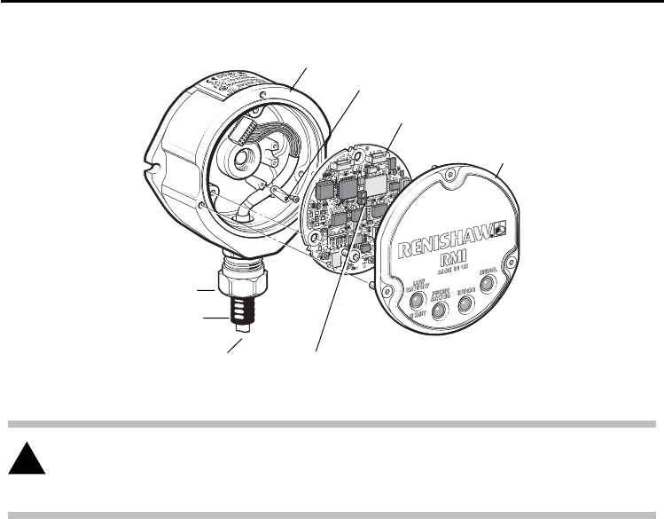
Removing the RMI cover
1. Clean RMI to ensure no debris enters unit.
2. Unscrew the three cover screws evenly
(T10 torx key). Do not remove screws
from cover.
3. When removing cover, do not twist or
rotate by hand.
RMI cover
RMI cover
23
RMI cover
RMI cover
CAUTION:
KEEP RMI CLEAN No liquids or solid particles must be allowed to enter the RMI body.
DO NOT allow the antenna contacts to be contaminated.
!
PCB
RMI body
Conduit adaptor
Conduit
Cable
Cable clamp
Antenna contacts

24 Side exit to rear exit cable conversion
1. Remove RMI cover (page 22).
2. Remove 3 crosshead screws retaining
PCB. Carefully remove PCB and
disconnect cable connection to PCB.
3. Unscrew cable clamp (2 x crosshead
screws).
4. Unscrew conduit gland from RMI body.
5. Unscrew rear exit plug and rubber
grommet from RMI body.
6. Carefully remove cable assembly and refit
through rear exit hole. Tighten conduit gland.
7. Fit rubber grommet and rear exit plug to side
exit hole and tighten.
8. Fit cable assembly using cable clamp at
3 o’clock position.
9. Connect PCB to cable connector. Insert
PCB and retain with 3 cross head screws.
10. Fit the RMI cover (page 22).
Side exit to rear exit cable conversion
CAUTION
Conversion from side exit cable
to rear exit cable must only be
undertaken by qualified personnel.
Failure to do so will invalidate the
warranty.
!
25
4 mm AF
5,1 Nm
(3.76 lbf.ft)
HOLD
3 mm AF
2 Nm
(1.47 lbf.ft)
Screw torque values Nm (lbf.ft).
Screw torque values
T10 tamper proof
1,4 Nm
(1.03 lbf.ft)
22,2 mm AF (7/8 AF)
Conduit adaptor to RMI body 10 Nm (7.38 lbf.ft)
Rear exit plug (not shown) 10 Nm (7.38 lbf.ft)
19 mm AF

26
Fault finding - If in doubt, consult your probe supplier.
Fault-finding
No power to RMI
Radio link failure - RMP60
out of RMI range
RMP60 has been enclosed /
shielded by metal
RMP60 and RMI are not
partnered
Dead RMP60 batteries
Damaged cable
Loss of power
Dead RMP60 batteries
No LEDs lit on RMI
RMI status LEDs do not
correspond to RMP60
status LEDs
RMI probe status LED
continually lit red
RMI error LED lit during
probing cycle
Check wiring
Check position of RMI,
see Operating envelope
(RMP60 User’s guide)
Review installation
Partner RMP60 and RMI
Change RMP60 batteries
Check wiring
Check wiring
Change RMP60 batteries
Symptom Cause Action

27
Fault-finding
Probe not switched on
Probe out of range
Wiring fault
Output over-current
Low RMP60 batteries
Local radio interference
RMI error LED illuminated
during intended probe
cycle
All RMI LEDs flashing
RMI low battery LED lit
Reduced range
Check configuration and alter
as required
Check position of RMI,
see Operating envelope
(RMP60 User’s guide)
Check wiring
Check wiring, turn power to
RMI off and on again to reset
Change RMP60 batteries soon
Identify and move
Symptom Cause Action

28
RMI A-4113-0050 RMI, side exit, with 15 m (49.2 ft) of cable.
Mtg Brkt A-2033-0830 Mounting bracket.
Conduit kit A-4113-0306 Conduit kit with 1 m (3.2 ft) of polyurethane conduit
and bulkhead connector (16 mm hole size required).
Cover assy A-4113-0305 Cover/antenna assembly: including cover screws, torx key and
O ring.
Cable assy A-4113-0302 Cable assembly 15 m (49.2 ft) long.
Cable assy A-4113-0303 Cable assembly 30 m (98.4 ft) long.
Cable assy A-4113-0304 Cable assembly 50 m (164 ft) long.
Tool kit A-4113-0300 T10 tamperproof key, 4 mm hex key, 14 x ferrules, 4 x M5
screw, 2 x M5 nut, 4 x M5 washer, O ring (Ø34,5 x 3 mm)
Type Part no. Description
The serial number of each RMI is found on the top of the housing.
Parts list - Please quote the part no. when ordering equipment.
Parts list