Renishaw plc RMP400 Radio Machine Probe User Manual
Renishaw plc Radio Machine Probe
UserManual.wiki
>
Renishaw plc
>
RMP400 User Manual
User Manual
Navigation menu
Upload a User Manual
Namespaces
Wiki Guide
HTML
PDF
Info
Views
User Manual
Discussion / Help
Navigation

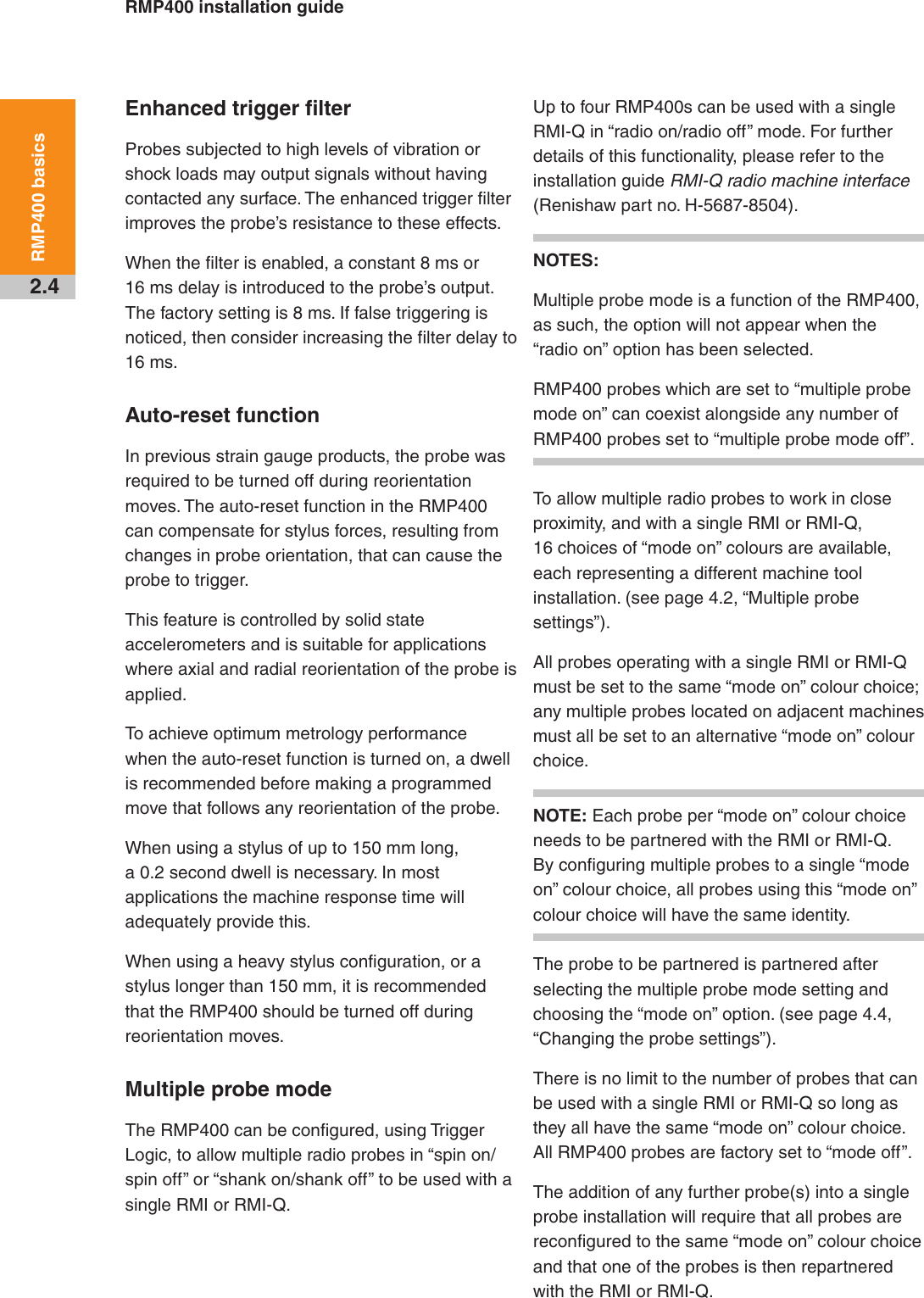
![1.5Before you beginSafetyInformation to the userThe RMP400 is supplied with two non-rechargeable ½AA lithium-thionyl chloride batteries (approved to BS EN 62133:2013 [IEC 62133:2012]). Once the charge in these batteries is depleted, do not attempt to recharge them.The use of this symbol on the batteries, packaging or accompanying documents indicates that used batteries should not be mixed with general household waste. Please dispose of the used batteries at a designated collection point. This will prevent potential negative effects on the environment and human health which could otherwise arise from inappropriate waste handling. Please contact your local authority or waste disposal service concerning the separate collection and disposal of batteries. All lithium and rechargeable batteries must be fully discharged or protected from short circuiting prior to disposal.Please ensure replacement batteries are of the correct type and are fitted in accordance with the instructions in this manual (see page 5.2, “Changing the batteries”), and as indicated on the product. For specific battery operating, safety and disposal guidelines, please refer to the battery manufacturer’s literature.• Ensure that all batteries are inserted with the correct polarity. • Do not store batteries in direct sunlight or rain. • Do not heat or dispose of batteries in a fire. • Avoid forced discharge of the batteries. • Do not short-circuit the batteries. • Do not disassemble, pierce, deform or apply excessive pressure to the batteries. • Do not swallow the batteries.• Keep the batteries out of the reach of children.• Do not get batteries wet.• If a battery is damaged, exercise caution when handling it.Please ensure that you comply with international and national battery transport regulations when transporting batteries or the products.Lithium batteries are classified as dangerous goods and strict controls apply to their shipment by air. To reduce the risk of shipment delays, if you need to return the products to Renishaw for any reason, do not return any batteries.In all applications involving the use of machine tools or CMMs, eye protection is recommended.The RMP400 has a glass window. Handle with care if broken to avoid injury.Information to the machine supplier/ installerIt is the machine supplier’s responsibility to ensure that the user is made aware of any hazards involved in operation, including those mentioned in Renishaw product literature, and to ensure that adequate guards and safety interlocks are provided.Under certain circumstances, the probe signal may falsely indicate a probe seated condition. Do not rely on probe signals to halt the movement of the machine.Information to the equipment installerAll Renishaw equipment is designed to comply with the relevant EC and FCC regulatory requirements. It is the responsibility of the equipment installer to ensure that the following guidelines are adhered to, in order for the product to function in accordance with these regulations:• any interface MUST be installed in a position away from any potential sources of electrical noise, i.e. power transformers, servo drives etc;• all 0 V/ground connections should be connected to the machine “star point” (the “star point” is a single point return for all equipment ground and screen cables). This is very important and failure to adhere to this can cause a potential difference between grounds;Draft 5 16/04/18](https://usermanual.wiki/Renishaw-plc/RMP400/User-Guide-3948278-Page-9.png)
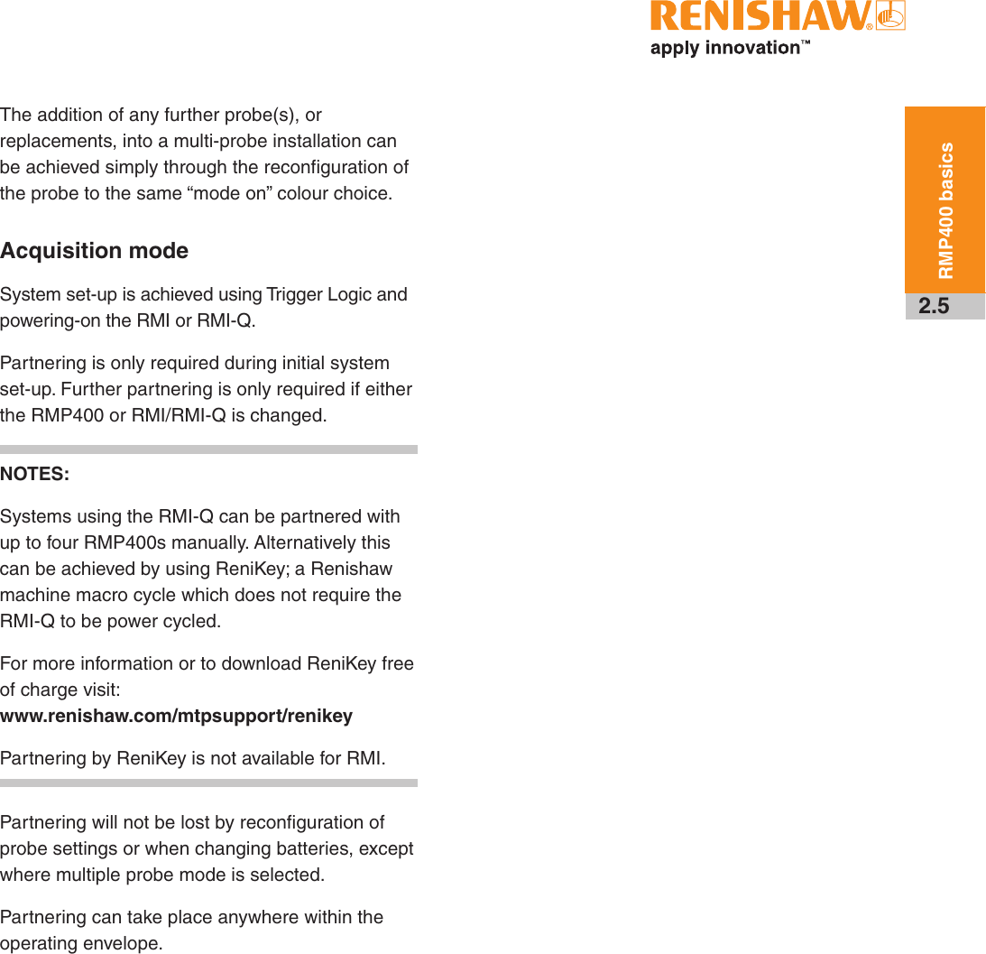
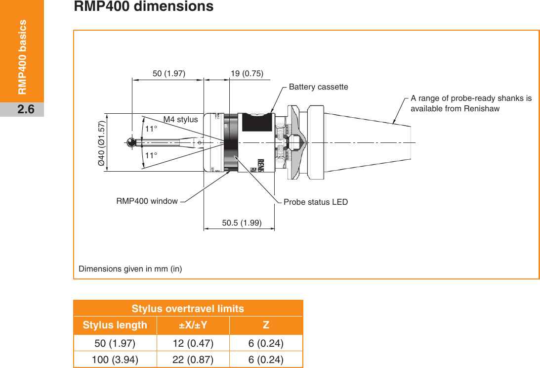
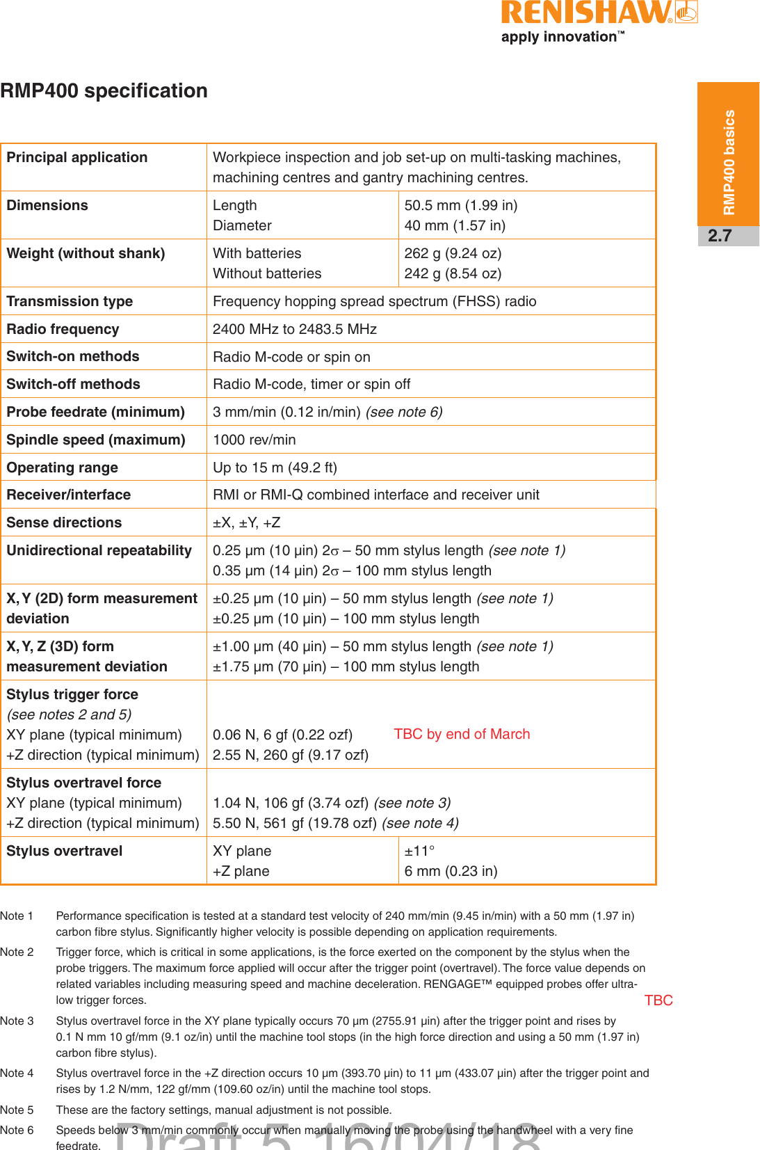
![RMP400 installation guide2.8RMP400 basicsEnvironment IP rating IPX8, BS EN 60529:1992+A2:2013 (IEC 60529:1989+A1:1999+A2:2013)IK rating IK01 (BS EN IEC 62262: 2002) [for glass window]Storage temperature –10 °C to +70 °C (+14 °F to +158 °F)Operating temperature +5 °C to +50 °C (+41 °F to +122 °F)Battery types 2 × ½AA 3.6 V lithium-thionyl chloride (LTC)Battery reserve life Approximately one week after a low battery warning is first given (based on 5% usage).Typical battery life See the table below.Typical battery lifeBattery typeSpin switch on Radio switch onContinuous useStandby life 5% usage(72 minutes/day)Standby life 5% usage(72 minutes/day)Lithium-thionyl chloride 230 days 90 days 230 days 90 days 165 hoursNOTE: Using RMP400 with “fast radio on” mode will result in a 20% reduction in standby battery life and a 10% reduction in 5% usage battery life.Draft 5 16/04/18](https://usermanual.wiki/Renishaw-plc/RMP400/User-Guide-3948278-Page-18.png)