Renishaw plc RMP400 Radio Machine Probe User Manual
Renishaw plc Radio Machine Probe
User Manual
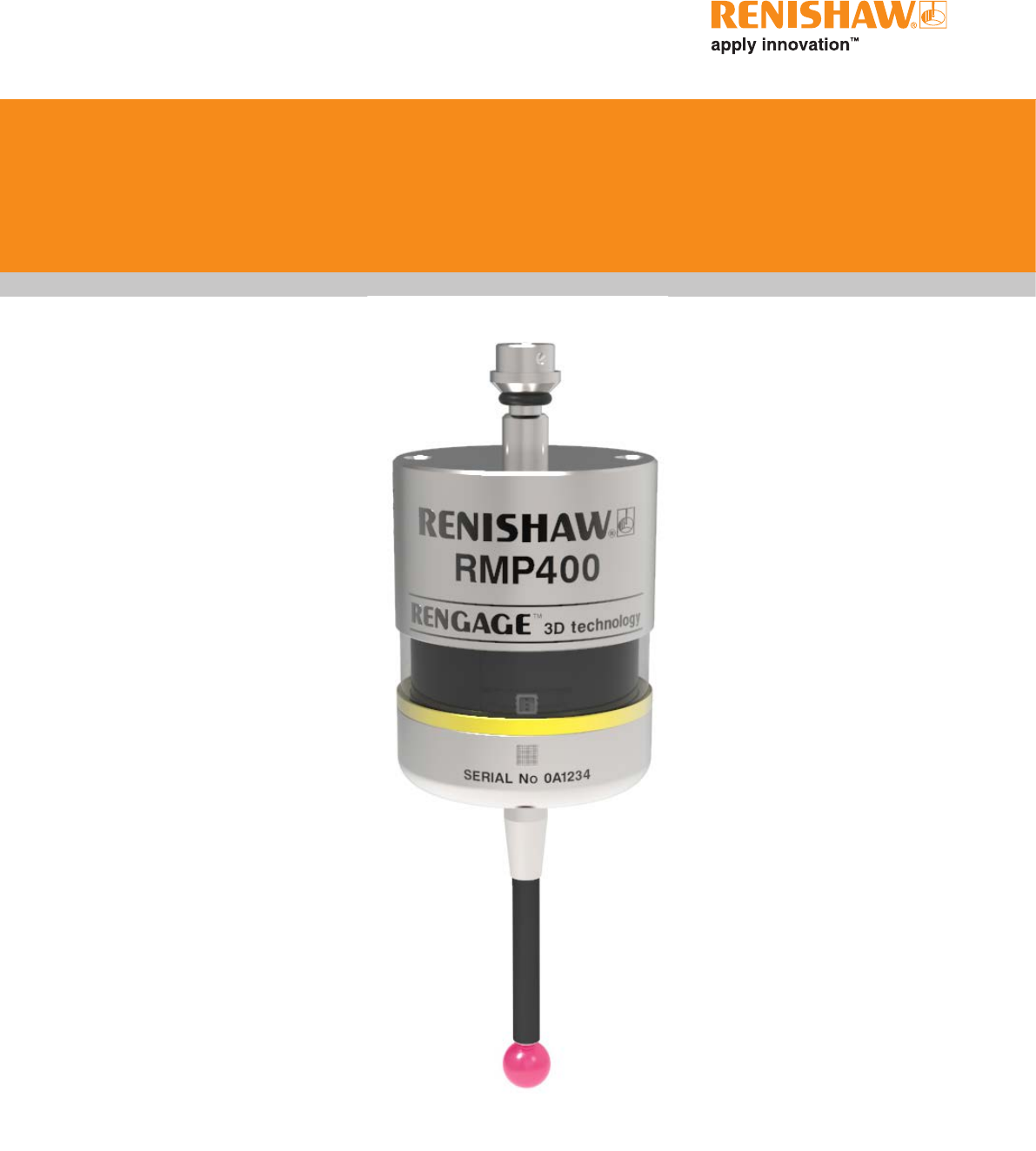
RMP400 high accuracy radio machine
probe
Installation guide
H-6570-8501-01-A
Draft 5 16/04/18
Renishaw part no: H-6570-8501-01-A
Issued: ??.????
© 2018 Renishaw plc. All rights reserved.
This document may not be copied or reproduced
in whole or in part, or transferred to any other
media or language, by any means, without the
prior written permission of Renishaw plc.
The publication of material within this document
does not imply freedom from the patent rights of
Renishaw plc.
Draft 5 16/04/18

i
Contents
Before you begin .............................................................1.1
Before you begin ............................................................1.1
Disclaimer ..............................................................1.1
Trade marks .............................................................1.1
Warranty ................................................................1.1
Changes to equipment .....................................................1.1
CNC machines ...........................................................1.1
Care of the probe .........................................................1.1
Patents .................................................................1.2
EU declaration of conformity ...................................................1.3
FCC Information to user (USA only) .............................................1.3
WEEE directive .............................................................1.3
Radio approval .............................................................1.4
Safety ....................................................................1.5
RMP400 basics ...............................................................2.1
Introduction ................................................................2.1
Getting started ...........................................................2.1
System interface ..........................................................2.2
Trigger Logic™ ...........................................................2.2
Probe modes ...............................................................2.2
Configurable settings .........................................................2.2
Switch-on/switch-off methods ................................................2.2
Enhanced trigger filter .....................................................2.4
Auto-reset function ........................................................2.4
Multiple probe mode ....................................................... 2.4
Acquisition mode .........................................................2.5
RMP400 dimensions .........................................................2.6
RMP400 specification ........................................................2.7
Recommended styli .......................................................... 2.9
Draft 5 16/04/18

RMP400 installation guide
ii
Contents
System installation ...........................................................3.1
Installing the RMP400 with an RMI or RMI-Q ......................................3.1
Operating envelope .......................................................3.1
Positioning the RMP400 and RMI or RMI-Q ....................................3.2
Performance envelope .....................................................3.2
Preparing the RMP400 for use .................................................3.3
Fitting the stylus ..........................................................3.3
Installing the batteries .....................................................3.4
Mounting the probe on a shank ..............................................3.5
Stylus on-centre adjustment ................................................. 3.6
Calibrating the RMP400 ......................................................3.7
Why calibrate a probe? ....................................................3.7
Calibrating in a bored hole or on a turned diameter ............................... 3.7
Calibrating in a ring gauge or on a datum sphere ................................3.7
Calibrating the probe length .................................................3.7
Trigger Logic™ ...............................................................4.1
Reviewing the probe settings ..................................................4.1
Multiple probe mode settings ..................................................4.2
Probe settings record ........................................................4.3
Changing the probe settings ...................................................4.4
RMP400 – RMI partnership .................................................... 4.6
RMP400 – RMI-Q partnership .................................................. 4.7
Operating mode ............................................................. 4.8
Maintenance .................................................................5.1
Maintenance ...............................................................5.1
Cleaning the probe ..........................................................5.1
Changing the batteries .......................................................5.2
Fault-finding .................................................................6.1
Parts list .....................................................................7.1
Draft 5 16/04/18

1.1
Changes to equipment
Renishaw reserves the right to change equipment
specifications without notice.
CNC machines
CNC machine tools must always be operated by
fully trained personnel in accordance with the
manufacturer’s instructions.
Care of the probe
Keep system components clean and treat the
probe as a precision tool.
Before you begin
Before you begin Warranty
Equipment requiring attention under warranty
must be returned to your equipment supplier.
Unless otherwise specifically agreed in writing
between you and Renishaw, if you purchased
the equipment from a Renishaw company, the
warranty provisions contained in Renishaw’s
CONDITIONS OF SALE apply. You should consult
these conditions in order to find out the details
of your warranty but, in summary, the main
exclusions from the warranty are if the equipment
has been:
• neglected, mishandled or inappropriately used;
or
• modified or altered in any way except with the
prior written agreement of Renishaw.
If you purchased the equipment from any other
supplier, you should contact them to find out what
repairs are covered by their warranty.
Disclaimer
RENISHAW HAS MADE CONSIDERABLE
EFFORTS TO ENSURE THE CONTENT OF THIS
DOCUMENT IS CORRECT AT THE DATE OF
PUBLICATION BUT MAKES NO WARRANTIES
OR REPRESENTATIONS REGARDING
THE CONTENT. RENISHAW EXCLUDES
LIABILITY, HOWSOEVER ARISING, FOR ANY
INACCURACIES IN THIS DOCUMENT.
Trade marks
RENISHAW and the probe symbol used in the
RENISHAW logo are registered trade marks of
Renishaw plc in the United Kingdom and other
countries. apply innovation and names and
designations of other Renishaw products and
technologies are trade marks of Renishaw plc or
its subsidiaries.
Google Play and the Google Play logo are
trademarks of Google LLC.
Apple and the Apple logo are trademarks of
Apple Inc., registered in the U.S. and other
countries. App Store is a service mark of Apple
Inc.,registered in the U.S. and other countries.
All other brand names and product names used
in this document are trade names, trade marks, or
registered trade marks of their respective owners.
see Section 1, “Before you begin”
Draft 5 16/04/18

1.2
Before you begin
Patents
Features of the RMP400, and other similar
Renishaw products, are the subject of one or
more of the following patents and/or patent
applications:
Patents will be listed
here when we have
them.. Possibly all
RMP40 patents and
strain gauge patents
(Steve to confirm)
Draft 5 16/04/18

1.3
Before you begin
C
FCC Information to user (USA
only)
47 CFR Section 15.19
This device complies with part 15 of the FCC
Rules. Operation is subject to the following two
conditions:
1. This device may not cause harmful
interference, and
2. This device must accept any interference
received, including interference that may
cause undesired operation.
47 CFR Section 15.21
The user is cautioned that any changes or
modifications not expressly approved by
Renishaw plc or authorised representative could
void the user’s authority to operate the equipment.
EU declaration of conformity
Renishaw plc declares that the RMP400 complies
with the applicable standards and regulations.
Contact Renishaw plc or visit
www.renishaw.com/mtpdoc for the full EU
declaration of conformity.
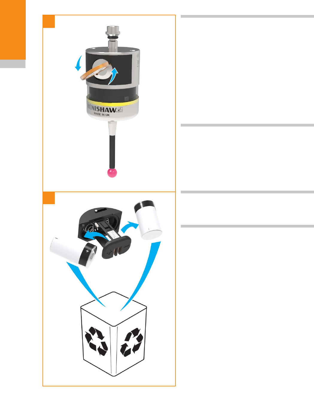
WEEE directive
The use of this symbol on Renishaw products
and/or accompanying documentation indicates
that the product should not be mixed with
general household waste upon disposal. It is the
responsibility of the end user to dispose of this
product at a designated collection point for waste
electrical and electronic equipment (WEEE) to
enable reuse or recycling. Correct disposal of
this product will help to save valuable resources
and prevent potential negative effects on the
environment. For more information, please contact
your local waste disposal service or Renishaw
distributor.
Draft 5 16/04/18

1.4
Before you begin
Radio approval
Will be listed here, when there are some (testing
to take place first).
Draft 5 16/04/18

1.5
Before you begin
Safety
Information to the user
The RMP400 is supplied with two non-
rechargeable ½AA lithium-thionyl chloride
batteries (approved to BS EN 62133:2013
[IEC 62133:2012]). Once the charge in these
batteries is depleted, do not attempt to recharge
them.
The use of this symbol on the batteries,
packaging or accompanying documents indicates
that used batteries should not be mixed with
general household waste. Please dispose of
the used batteries at a designated collection
point. This will prevent potential negative effects
on the environment and human health which
could otherwise arise from inappropriate waste
handling. Please contact your local authority or
waste disposal service concerning the separate
collection and disposal of batteries. All lithium and
rechargeable batteries must be fully discharged or
protected from short circuiting prior to disposal.
Please ensure replacement batteries are of the
correct type and are fitted in accordance with
the instructions in this manual (see page 5.2,
“Changing the batteries”), and as indicated on the
product. For specific battery operating, safety and
disposal guidelines, please refer to the battery
manufacturer’s literature.
• Ensure that all batteries are inserted with the
correct polarity.
• Do not store batteries in direct sunlight or rain.
• Do not heat or dispose of batteries in a fire.
• Avoid forced discharge of the batteries.
• Do not short-circuit the batteries.
• Do not disassemble, pierce, deform or apply
excessive pressure to the batteries.
• Do not swallow the batteries.
• Keep the batteries out of the reach of children.
• Do not get batteries wet.
• If a battery is damaged, exercise caution when
handling it.
Please ensure that you comply with international
and national battery transport regulations when
transporting batteries or the products.
Lithium batteries are classified as dangerous
goods and strict controls apply to their shipment
by air. To reduce the risk of shipment delays, if you
need to return the products to Renishaw for any
reason, do not return any batteries.
In all applications involving the use of machine
tools or CMMs, eye protection is recommended.
The RMP400 has a glass window. Handle with
care if broken to avoid injury.
Information to the machine supplier/
installer
It is the machine supplier’s responsibility to ensure
that the user is made aware of any hazards
involved in operation, including those mentioned
in Renishaw product literature, and to ensure
that adequate guards and safety interlocks are
provided.
Under certain circumstances, the probe signal
may falsely indicate a probe seated condition. Do
not rely on probe signals to halt the movement of
the machine.
Information to the equipment installer
All Renishaw equipment is designed to comply
with the relevant EC and FCC regulatory
requirements. It is the responsibility of the
equipment installer to ensure that the following
guidelines are adhered to, in order for the product
to function in accordance with these regulations:
• any interface MUST be installed in a position
away from any potential sources of electrical
noise, i.e. power transformers, servo drives etc;
• all 0 V/ground connections should be
connected to the machine “star point” (the “star
point” is a single point return for all equipment
ground and screen cables). This is very
important and failure to adhere to this can
cause a potential difference between grounds;
Draft 5 16/04/18

1.6
Before you begin
• all screens must be connected as outlined in
the user instructions;
• cables must not be routed alongside high
current sources, i.e. motor power supply cables
etc, or be near high-speed data lines;
• cable lengths should always be kept to a
minimum.
Equipment operation
If this equipment is used in a manner not specified
by the manufacturer, the protection provided by
the equipment may be impaired.
Draft 5 16/04/18

2.1
RMP400 basics
Introduction
The RMP400 offers an unrivalled combination
of size, accuracy, reliability and robustness
and, allows high-accuracy probing on small to
medium machining centres or other machines
where line-of-sight problems affect optical signal
transmission.
Successfully combining patented RENGAGE™
strain gauge technology with the patented
frequency hopping radio transmission system of
the RMP40, the RMP400 provides existing probe
users with a simple upgrade to solid-state strain
gauge technology and all the associated benefits
this brings:
• excellent 3D performance to allow probing of
contoured surfaces;
• improved repeatability in all probing directions;
• a low triggering force combined with low pre-
travel variation to provide high accuracy, even
when used with long styli;
• a proven ten-fold improvement in life (10 million
triggers); ????
• the elimination of reseat failures;
• high resistance to machine tool vibration;
• resistance to shock and false triggering
through the use of solid state accelerometers.
In addition to providing high-accuracy
measurement on your machine tool, the RMP400
also offers:
• Faster calibration:
On complex 3D parts, it is common to
measure in several different directions. Each
direction of a standard mechanical probe must
be calibrated, to ensure that the pre-travel
variation is compensated in the measurement.
Performing this calibration for every 3D
direction can be time-consuming.
The RMP400 has almost no pre-travel
variation, so a single calibration value may be
used for any probing angle in 2D or 3D. This
results in a vastly reduced calibration time. An
additional benefit is a corresponding reduction
in errors introduced by environmental changes
within the machine during a long calibration
cycle.
• The ability to be used in applications
where axial and radial reorientations are
used, enabled by the use of solid state
accelerometers:
The auto-reset function is required and
recommendations should be followed for
optimum metrology performance.
Getting started
Three multicolour probe LEDs provide visual
indication of selected probe settings.
For example:
• Switch-on and switch-off methods
• Probe status – triggered or seated
• Battery condition
Batteries are inserted or removed as shown (see
page 3.5, “Installing the batteries”) for further
information).
On insertion of batteries, the LEDs will begin
to flash (see page 4.1, “Reviewing the probe
settings”).
see Section 2, “RMP400 basics”
Draft 5 16/04/18

2.2
RMP400 basics
System interface
The RMI and RMI-Q are integrated interfaces/
receivers used to communicate between the
RMP400 probe and the machine control.
Trigger Logic™
Trigger Logic (see Section 4, “Trigger Logic™”) is
a method that allows the user to view and select
all available mode settings in order to customise
a probe to suit a specific application. Trigger
Logic is activated by battery insertion and uses
a sequence of stylus deflections (triggering) to
systematically lead the user through the available
choices to allow selection of the required mode
options.
A Trigger Logic app is available that simplifies this
process with clear, interactive instructions and
informative videos and is available for download
on the following app stores.
or
Current probe settings can be reviewed by
simply removing the batteries for a minimum of
five seconds, and then replacing them to activate
the Trigger Logic review sequence.
Probe modes
The RMP400 probe can be in one of three modes:
Standby mode – Probe is waiting for a switch-on
signal.
NOTE: The RMP400 will enter hibernation mode
should the system interface be powered off or
out of range for a period of 30 seconds (only
applicable to “radio on” mode).
Operational mode – When activated by one of
the switch-on methods, the probe is switched on
and ready for use.
Configuration mode – Ready to change the
probe settings using Trigger Logic.
Configurable settings
Switch-on/switch-off methods
The following switch-on/switch-off options are
user-configurable.
•Radio on/Radio off
•Radio on/Timer off
•Spin on/Spin off
•Spin on/Timer off
Draft 5 16/04/18

2.3
RMP400 basics
RMP400 switch-on method
Switch-on options are configurable
RMP400 switch-off method
Switch-off options are configurable
Probe ready time
Radio on
Radio switch on is commanded by
machine input.
Radio off
Radio switch off is commanded by
machine input. A timer automatically
switches the probe off 90 minutes
after the last trigger if it is not turned
off by machine input.
Timer off (timeout)
Timeout will occur 12, 33 or 134
seconds (user configurable) after the
last probe trigger or reseat.
1.7 seconds
maximum.
Spin on
Spin at 500 rev/min for one second
minimum.
Spin off
Spin at 500 rev/min for one second
minimum. A timer automatically
switches the probe off 90 minutes
after the last trigger if it is not spun.
Timer off (timeout)
Timeout will occur 12, 33 or 134
seconds (user configurable) after the
last probe trigger or reseat.
2.5 seconds. (The
probe must be
stationary for 2.5
seconds minimum
after it has stopped
spinning.)
NOTES:
In “radio on” mode, the switch-on time is user
selectable “fast” or “standard” when using
RMI-Q (selection is made in RMI-Q). Otherwise
1.7 seconds.
For more information on the user selectable
switch-on time when operating with RMI-Q, please
refer to the installation guide RMI-Q radio machine
interface (Renishaw part no. H-5687-8504).
In “radio on” mode, the switch-on time assumes
a good radio communication link. In a poor RF
environment this may rise to a maximum of
3.0 seconds.
In “spin on” mode, the one second starts from
the moment the spindle reaches 500 rev/min.
The RMP400 must be on for a minimum of
one second before being switched off.
Draft 5 16/04/18

RMP400 installation guide
2.4
RMP400 basics
Enhanced trigger filter
Probes subjected to high levels of vibration or
shock loads may output signals without having
contacted any surface. The enhanced trigger filter
improves the probe’s resistance to these effects.
When the filter is enabled, a constant 8 ms or
16 ms delay is introduced to the probe’s output.
The factory setting is 8 ms. If false triggering is
noticed, then consider increasing the filter delay to
16 ms.
Auto-reset function
In previous strain gauge products, the probe was
required to be turned off during reorientation
moves. The auto-reset function in the RMP400
can compensate for stylus forces, resulting from
changes in probe orientation, that can cause the
probe to trigger.
This feature is controlled by solid state
accelerometers and is suitable for applications
where axial and radial reorientation of the probe is
applied.
To achieve optimum metrology performance
when the auto-reset function is turned on, a dwell
is recommended before making a programmed
move that follows any reorientation of the probe.
When using a stylus of up to 150 mm long,
a 0.2 second dwell is necessary. In most
applications the machine response time will
adequately provide this.
When using a heavy stylus configuration, or a
stylus longer than 150 mm, it is recommended
that the RMP400 should be turned off during
reorientation moves.
Multiple probe mode
The RMP400 can be configured, using Trigger
Logic, to allow multiple radio probes in “spin on/
spin off” or “shank on/shank off” to be used with a
single RMI or RMI-Q.
Up to four RMP400s can be used with a single
RMI-Q in “radio on/radio off” mode. For further
details of this functionality, please refer to the
installation guide RMI-Q radio machine interface
(Renishaw part no. H-5687-8504).
NOTES:
Multiple probe mode is a function of the RMP400,
as such, the option will not appear when the
“radio on” option has been selected.
RMP400 probes which are set to “multiple probe
mode on” can coexist alongside any number of
RMP400 probes set to “multiple probe mode off”.
To allow multiple radio probes to work in close
proximity, and with a single RMI or RMI-Q,
16 choices of “mode on” colours are available,
each representing a different machine tool
installation. (see page 4.2, “Multiple probe
settings”).
All probes operating with a single RMI or RMI-Q
must be set to the same “mode on” colour choice;
any multiple probes located on adjacent machines
must all be set to an alternative “mode on” colour
choice.
NOTE: Each probe per “mode on” colour choice
needs to be partnered with the RMI or RMI-Q.
By configuring multiple probes to a single “mode
on” colour choice, all probes using this “mode on”
colour choice will have the same identity.
The probe to be partnered is partnered after
selecting the multiple probe mode setting and
choosing the “mode on” option. (see page 4.4,
“Changing the probe settings”).
There is no limit to the number of probes that can
be used with a single RMI or RMI-Q so long as
they all have the same “mode on” colour choice.
All RMP400 probes are factory set to “mode off”.
The addition of any further probe(s) into a single
probe installation will require that all probes are
reconfigured to the same “mode on” colour choice
and that one of the probes is then repartnered
with the RMI or RMI-Q.
Draft 5 16/04/18

2.5
RMP400 basics
The addition of any further probe(s), or
replacements, into a multi-probe installation can
be achieved simply through the reconfiguration of
the probe to the same “mode on” colour choice.
Acquisition mode
System set-up is achieved using Trigger Logic and
powering-on the RMI or RMI-Q.
Partnering is only required during initial system
set-up. Further partnering is only required if either
the RMP400 or RMI/RMI-Q is changed.
NOTES:
Systems using the RMI-Q can be partnered with
up to four RMP400s manually. Alternatively this
can be achieved by using ReniKey; a Renishaw
machine macro cycle which does not require the
RMI-Q to be power cycled.
For more information or to download ReniKey free
of charge visit:
www.renishaw.com/mtpsupport/renikey
Partnering by ReniKey is not available for RMI.
Partnering will not be lost by reconfiguration of
probe settings or when changing batteries, except
where multiple probe mode is selected.
Partnering can take place anywhere within the
operating envelope.
Draft 5 16/04/18
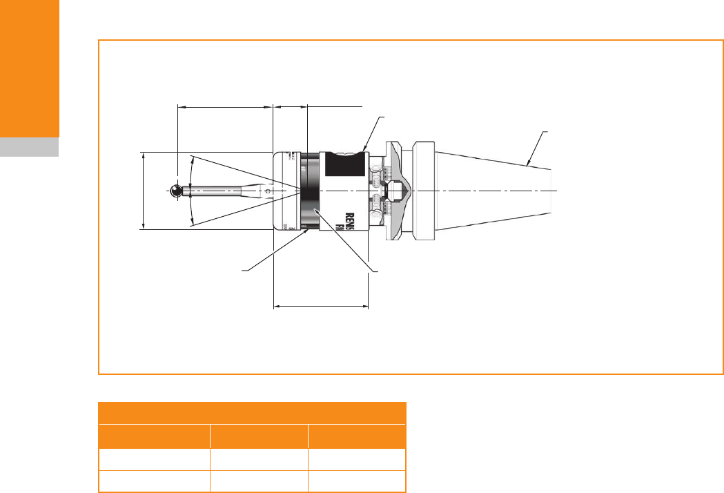
A range of probe-ready shanks is
available from Renishaw
50.5 (1.99)
19 (0.75)
Battery cassette
RMP400 window
11°
11°
Ø40 (Ø1.57)
50 (1.97)
M4 stylus
Probe status LED
2.6
RMP400 basics
RMP400 dimensions
Dimensions given in mm (in)
Stylus overtravel limits
Stylus length ±X/±Y Z
50 (1.97) 12 (0.47) 6 (0.24)
100 (3.94) 22 (0.87) 6 (0.24)
Draft 5 16/04/18

2.7
RMP400 basics
RMP400 specification
Principal application Workpiece inspection and job set-up on multi-tasking machines,
machining centres and gantry machining centres.
Dimensions Length
Diameter
50.5 mm (1.99 in)
40 mm (1.57 in)
Weight (without shank) With batteries
Without batteries
262 g (9.24 oz)
242 g (8.54 oz)
Transmission type Frequency hopping spread spectrum (FHSS) radio
Radio frequency 2400 MHz to 2483.5 MHz
Switch-on methods Radio M-code or spin on
Switch-off methods Radio M-code, timer or spin off
Probe feedrate (minimum) 3 mm/min (0.12 in/min) (see note 6)
Spindle speed (maximum) 1000 rev/min
Operating range Up to 15 m (49.2 ft)
Receiver/interface RMI or RMI-Q combined interface and receiver unit
Sense directions ±X, ±Y, +Z
Unidirectional repeatability 0.25 µm (10 µin) 2s – 50 mm stylus length (see note 1)
0.35 µm (14 µin) 2s – 100 mm stylus length
X, Y (2D) form measurement
deviation
±0.25 µm (10 µin) – 50 mm stylus length (see note 1)
±0.25 µm (10 µin) – 100 mm stylus length
X, Y, Z (3D) form
measurement deviation
±1.00 µm (40 µin) – 50 mm stylus length (see note 1)
±1.75 µm (70 µin) – 100 mm stylus length
Stylus trigger force
(see notes 2 and 5)
XY plane (typical minimum)
+Z direction (typical minimum)
0.06 N, 6 gf (0.22 ozf)
2.55 N, 260 gf (9.17 ozf)
Stylus overtravel force
XY plane (typical minimum)
+Z direction (typical minimum)
1.04 N, 106 gf (3.74 ozf) (see note 3)
5.50 N, 561 gf (19.78 ozf) (see note 4)
Stylus overtravel XY plane
+Z plane
±11°
6 mm (0.23 in)
Note 1 Performance specification is tested at a standard test velocity of 240 mm/min (9.45 in/min) with a 50 mm (1.97 in)
carbon fibre stylus. Significantly higher velocity is possible depending on application requirements.
Note 2 Trigger force, which is critical in some applications, is the force exerted on the component by the stylus when the
probe triggers. The maximum force applied will occur after the trigger point (overtravel). The force value depends on
related variables including measuring speed and machine deceleration. RENGAGE™ equipped probes offer ultra-
low trigger forces.
Note 3 Stylus overtravel force in the XY plane typically occurs 70 µm (2755.91 µin) after the trigger point and rises by
0.1 N mm 10 gf/mm (9.1 oz/in) until the machine tool stops (in the high force direction and using a 50 mm (1.97 in)
carbon fibre stylus).
Note 4 Stylus overtravel force in the +Z direction occurs 10 µm (393.70 µin) to 11 µm (433.07 µin) after the trigger point and
rises by 1.2 N/mm, 122 gf/mm (109.60 oz/in) until the machine tool stops.
Note 5 These are the factory settings, manual adjustment is not possible.
Note 6 Speeds below 3 mm/min commonly occur when manually moving the probe using the handwheel with a very fine
feedrate.
TBC by end of March
TBC
Draft 5 16/04/18

RMP400 installation guide
2.8
RMP400 basics
Environment IP rating IPX8, BS EN 60529:1992+A2:2013
(IEC 60529:1989+A1:1999+A2:2013)
IK rating IK01 (BS EN IEC 62262: 2002) [for glass
window]
Storage temperature –10 °C to +70 °C (+14 °F to +158 °F)
Operating temperature +5 °C to +50 °C (+41 °F to +122 °F)
Battery types 2 × ½AA 3.6 V lithium-thionyl chloride (LTC)
Battery reserve life Approximately one week after a low battery warning is first given (based
on 5% usage).
Typical battery life See the table below.
Typical battery life
Battery type
Spin switch on Radio switch on
Continuous use
Standby life 5% usage
(72 minutes/day)
Standby life 5% usage
(72 minutes/day)
Lithium-thionyl
chloride 230 days 90 days 230 days 90 days 165 hours
NOTE: Using RMP400 with “fast radio on” mode will result in a 20% reduction in standby battery life
and a 10% reduction in 5% usage battery life.
Draft 5 16/04/18
2.9
RMP400 basics
A
D
C
B
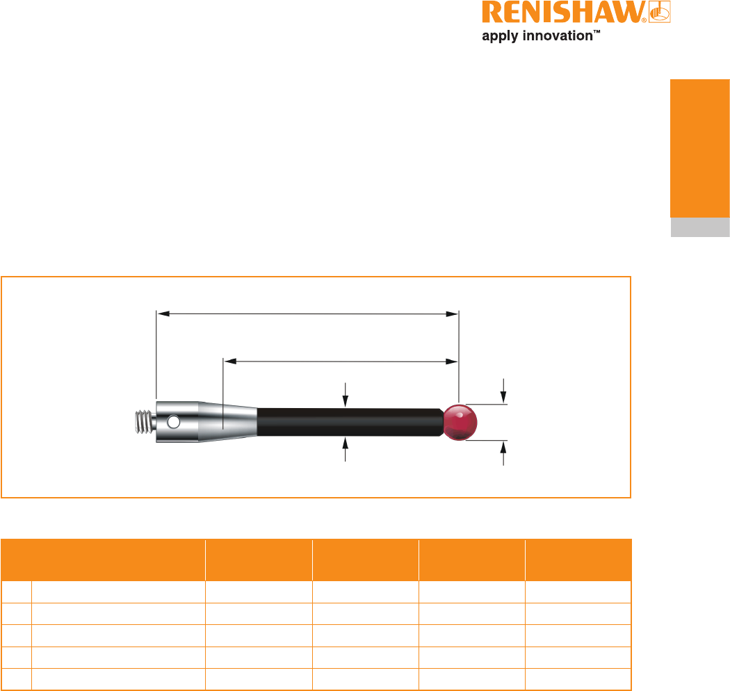
Recommended styli
High modulus carbon fibre styli are designed to
minimise pre-travel and improve accuracy, as
the stem material is extremely stiff. This inherent
stiffness makes the following styli most suitable for
strain gauge applications.
Part number A-5003-7306
Carbon fibre
A-5003-6510
Carbon fibre
A-5003-6511
Carbon fibre
A-5003-6512
Carbon fibre
ABall diameter mm (inch) 6 (0.24) 6 (0.24) 6 (0.24) 6 (0.24)
BLength mm (inch) 50 (1.97) 100 (3.94) 150 (5.91) 200 (7.88)
CStem diameter mm (inch) 4.5 (0.18) 4.5 (0.18) 4.5 (0.18) 4.5 (0.18)
DEWL mm (inch) 38.5 (1.52) 88.5 (3.48) 138.5 (5.45) 188.5 (7.42)
Mass in g (oz) 4.1 (0.14) 6.2 (0.22) 7.5 (0.26) 8.7 (0.31)
The featured range of solid carbon fibre styli
ensure the best possible performance of the
RMP400.
It is possible that the featured range of solid
carbon fibre styli may not be suitable for every
RMP400 application and that it may be necessary
to select specialised styli configurations to meet
specific application requirements.
In applications where specialised styli are to be
used, it may be beneficial to reduce the speed of
probing moves. It has been seen in some cases
that specialist styli configurations do not exhibit
the probing characteristics and performance
that would have otherwise been expected and
achieved when using standard styli. Reducing the
speed of the probing move may, in some cases,
improve the performance of the probe.
When selecting components for an application
specific stylus, it is recommended that
a configuration with the least number of
components is chosen. The stylus diameter
should always be as large as possible and the
overall stylus length kept to a minimum. If a stem
with a reduced diameter is required, then it is
recommended that an M4 stem with a short length
and reduced diameter is selected.
Draft 5 16/04/18

2.10
RMP400 basics
This page is intentionally left blank.
Draft 5 16/04/18
3.1
System installation
see Section 3, “System installation”
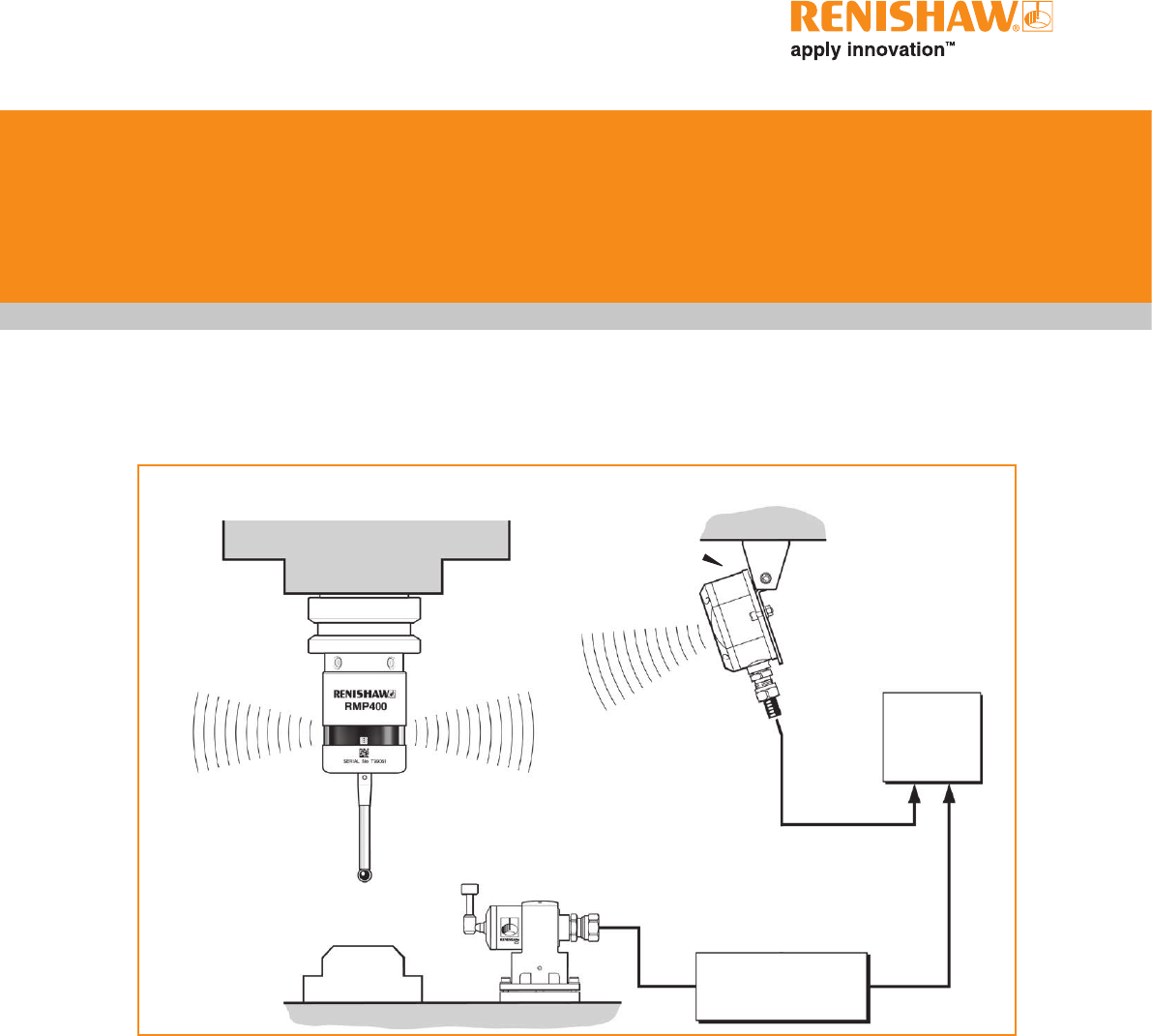
Installing the RMP400 with an RMI or RMI-Q
CNC machining
centre spindle
RMP400
inspection probe
RMI or RMI-Q
interface Mounting
bracket
CNC
machine
control
Interface unit
Typical tool
setting probe Cable
Workpiece
Stylus
Operating envelope
Radio transmission does not require line-of-sight
between the probe and interface as it works
via reflected paths, and will pass through gaps
and machine tool windows. This allows easy
installation, either inside or outside the machine
enclosure, as long as the probe and RMI or
RMI-Q are kept within the performance envelope
shown overleaf.
Coolant and swarf residue accumulating on
the RMP400 and RMI or RMI-Q may have a
detrimental effect on transmission performance.
Wipe clean as often as is necessary to maintain
unrestricted transmission.
When operating, do not cover the probe glass
window, RMI or RMI-Q with your hands, as this
will affect the performance.
Draft 5 16/04/18
3.2
System
installation
Positioning the RMP400 and RMI or
RMI-Q
The probe system should be positioned so that
the optimum range can be achieved over the full
travel of the machine’s axes. Always face the front
cover of the RMI or RMI-Q in the general direction
of the machining area and the tool magazine,
ensuring both are within the performance
envelope shown below. To assist in finding the
optimum position of the RMI or RMI-Q, the signal
quality is displayed on an RMI or RMI-Q signal
LED.
NOTE: Installing the RMP400 and RMI or RMI-Q
with the RMP400 in radio-on configuration
The RMP400 has a built-in hibernation mode
(battery-saving mode) that saves battery life
when the RMI or RMI-Q is unpowered in radio-on
(radio-off or timer-off) configurations. The RMP400
goes into hibernation mode 30 seconds after
the RMI or RMI-Q is unpowered (or the RMP400
is out of range). When in hibernation mode, the
RMP400 checks for a powered RMI or RMI-Q
every 30 seconds. If found, the RMP400 goes
from hibernation mode to standby mode, ready for
radio-on.
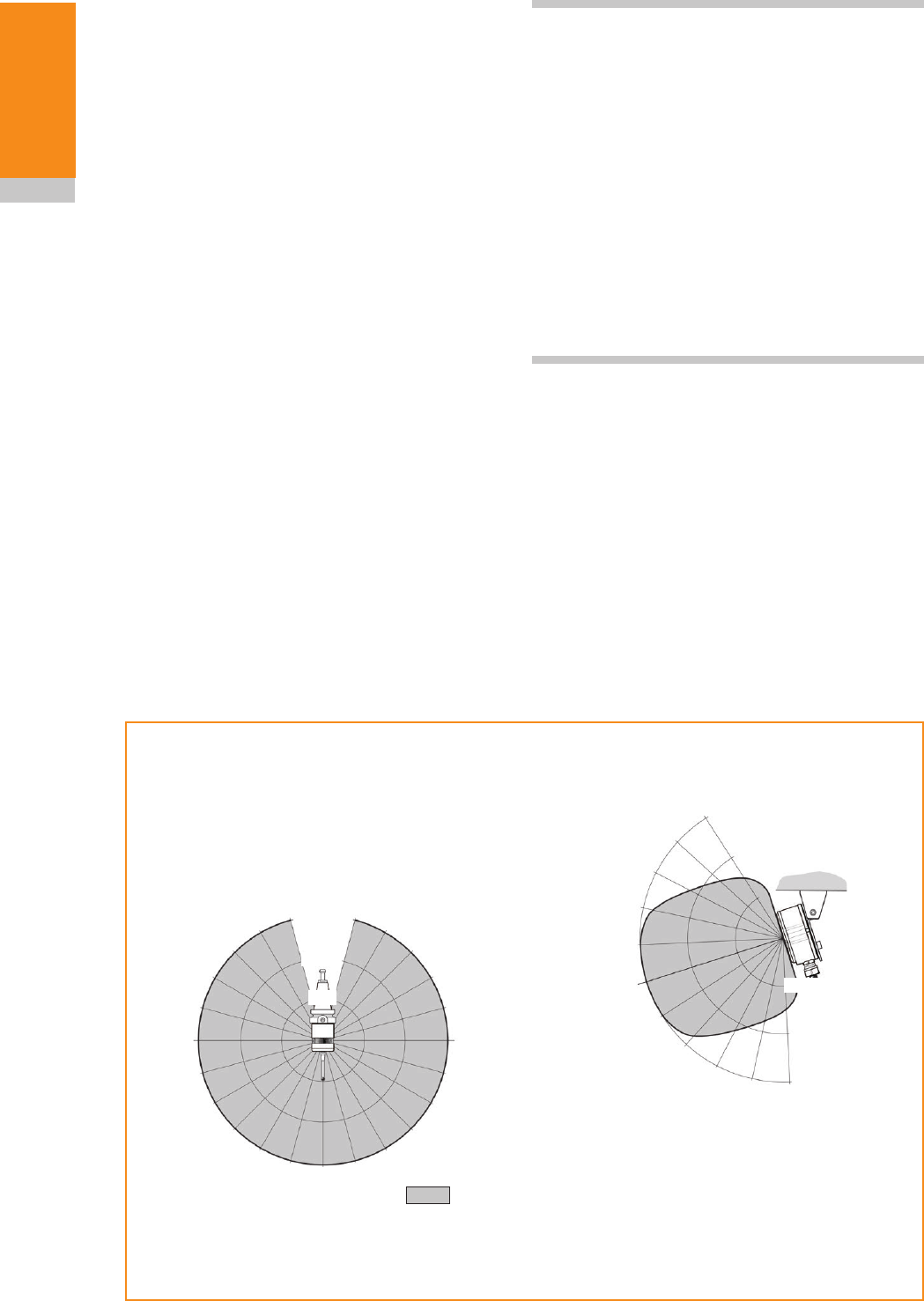
Performance envelope
The RMP400 and RMI or RMI-Q must be within
each other’s performance envelope, as shown
below. The performance envelope shows line-of-
sight performance, however, this is not necessary
for the RMP400 radio transmission as it will
operate with any reflected radio path provided
that the reflected path length does not exceed the
15 m (49.2 ft) operating range.
Typical plot at +20 °C (+68 °F)
Transmission range in m (ft)
Performance envelope when using the RMP400 with the RMI or RMI-Q
75°
60°
45°
30°
15°
0°
15°
30°
45°
60°
75° 90° 75°
60°
45°
30°
15°
0°
15°
45°
60°
75°
75°
60°
45°
30°
30°
45°
60° 75°
10 (33)
15 (49)
15°
0°
15°
30°
5 (16)
10 (33)
15 (49)
Operating and switch-on / switch-off
5 (16)
Draft 5 16/04/18
1
2
3.3
System
installation
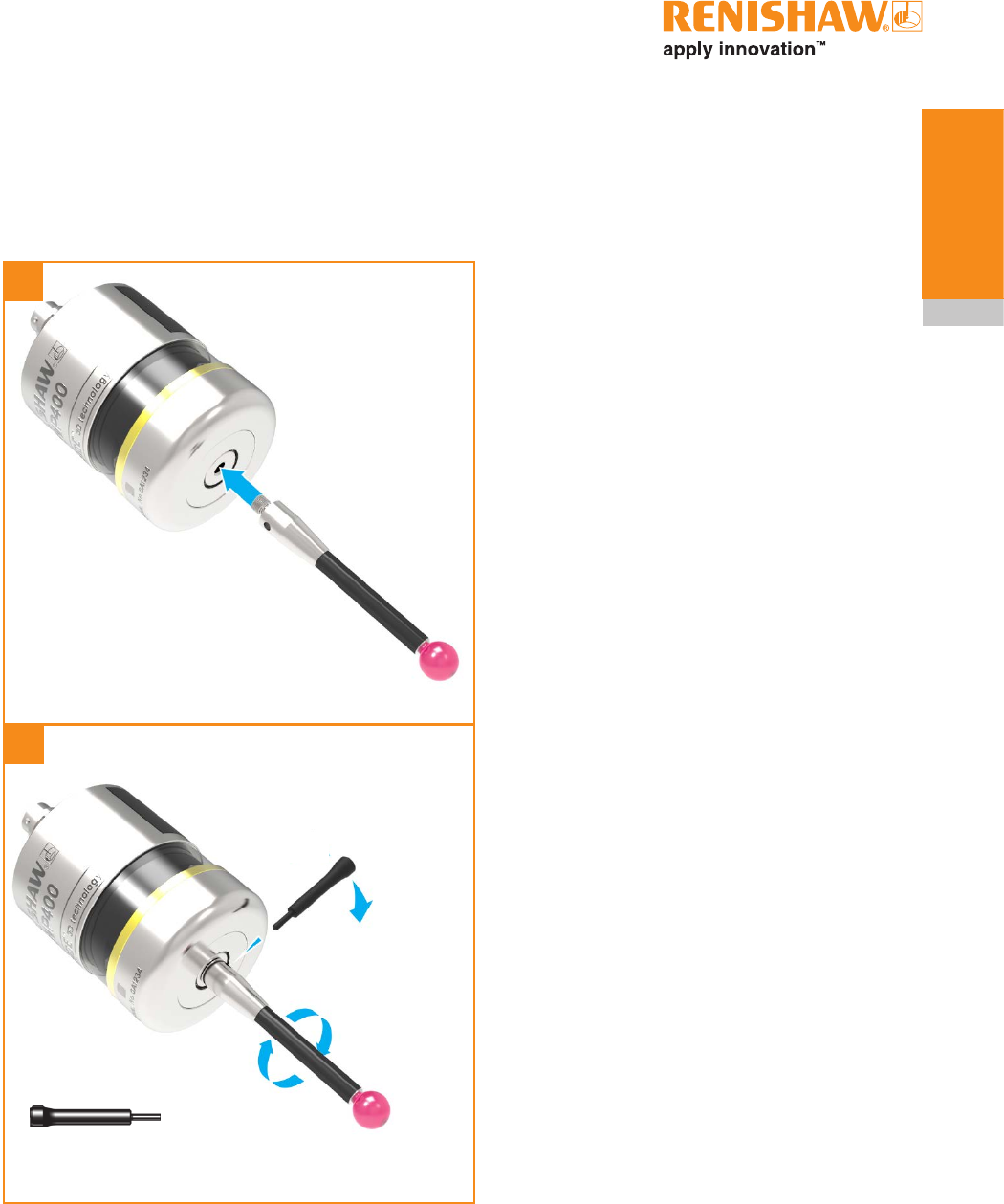
Preparing the RMP400 for use
Fitting the stylus
M-5000-3707
1.8 Nm – 2.2 Nm
(1.3 lbf.ft – 1.6 lbf.ft)
Draft 5 16/04/18
3.4
System
installation
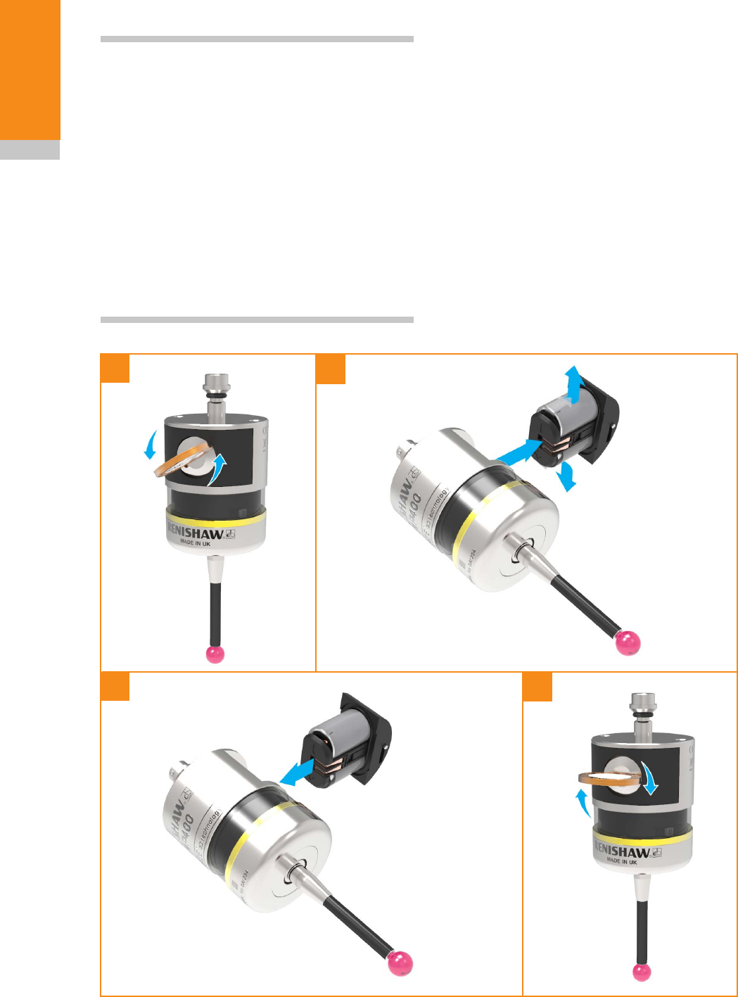
Installing the batteries
NOTES:
See (Section 5,“Maintenance”)for a list of suitable
battery types.
If dead batteries are inadvertently inserted, the
LEDs will remain a constant red.
Do not allow coolant or debris to enter the battery
compartment. When inserting batteries, check that
the battery polarity is correct.
After the batteries have been inserted, the LEDs
will display the current probe settings, for details,
(see Section 4, “Trigger Logic™”).
1
4
Please remove the
battery isolation device
from the battery
compartment before use.
2
3
Draft 5 16/04/18
3.5
System
installation
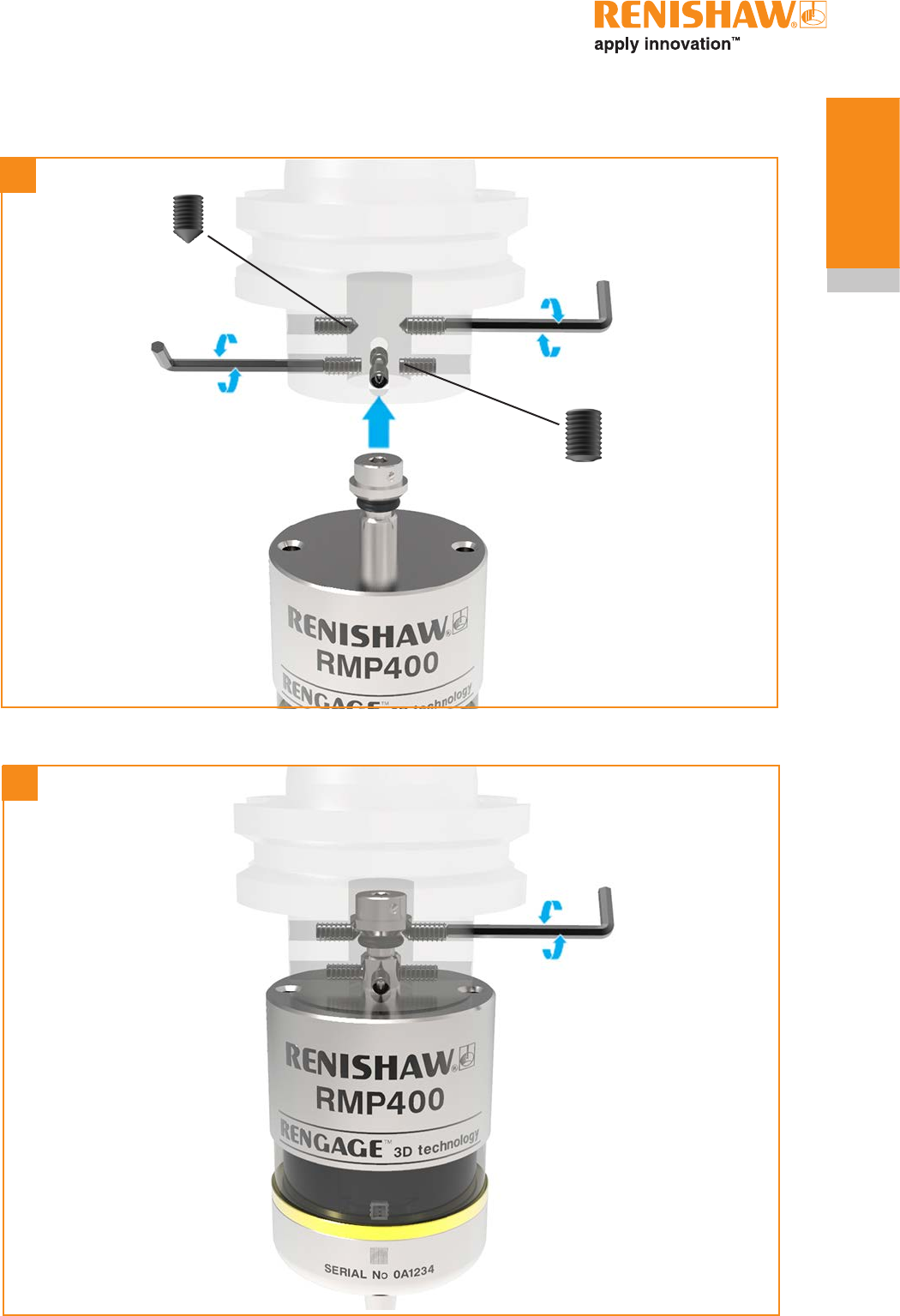
Mounting the probe on a shank
2 mm A/F
× 2
2 mm A/F
× 4
× 4
× 2
2 mm A/F
× 2
0.5 Nm – 1.5 Nm
(0.4 lbf.ft – 1.1 lbf.ft)
1
2
Draft 5 16/04/18
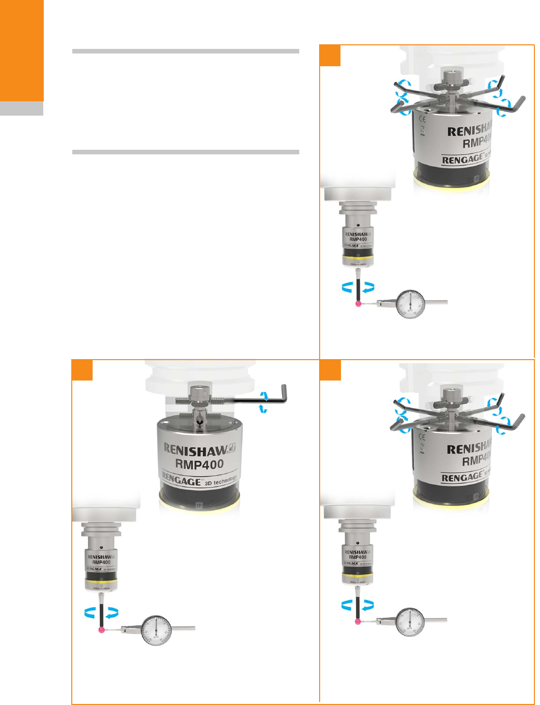
1
23
±2.5 µm
±10 µm
±10 µm
3.6
System
installation
Stylus on-centre adjustment
1.5 Nm – 2.2 Nm
(1.1 lbf.ft – 1.6 lbf.ft)
1.5 Nm – 2.2 Nm
(1.1 lbf.ft – 1.6 lbf.ft)
NOTES:
If a probe and shank assembly is dropped, it must
be rechecked for correct on-centre adjustment.
Do not hit or tap the probe to achieve on-centre
adjustment.
× 4
× 2
× 4
360°
360°
360°
Draft 5 16/04/18

3.7
System
installation
Calibrating the RMP400
Why calibrate a probe?
A spindle probe is just one component of the
measurement system which communicates with
the machine tool. Each part of the system can
introduce a constant difference between the
position that the stylus touches and the position
that is reported to the machine. If the probe is
not calibrated, this difference will appear as an
inaccuracy in the measurement. Calibration of the
probe allows the probing software to compensate
for this difference.
During normal use, the difference between the
touch position and the reported position does
not change, but it is important that the probe is
calibrated in the following circumstances:
•when a probe system is to be used for the first
time;
•when the enhanced trigger filter delay is
changed;
•when a new stylus is fitted to the probe;
•when it is suspected that the stylus has
become distorted or that the probe has been
crashed;
•at regular intervals to compensate for
mechanical changes of your machine tool;
•if repeatability of relocation of the probe shank
is poor. In this case, the probe may need to be
recalibrated each time it is selected.
It is good practice to set the tip of the stylus on-
centre, because this reduces the effect of any
variation in spindle and tool orientation (see page
3.6, “Stylus on-centre adjustment”). A small
amount of run-out is acceptable, and can be
compensated for as part of the normal calibration
process.
Three different operations are to be used when
calibrating a probe. They are:
•calibrating either in a bored hole or on a turned
diameter of known position;
•calibrating either in a ring gauge or on a datum
sphere;
•calibrating the probe length.
Calibrating in a bored hole or on a
turned diameter
Calibrating a probe, either in a bored hole or on
a turned diameter of known size, automatically
stores values for the offset of the stylus ball to
the spindle centre line. The stored values are
then used automatically in the measuring cycles.
Measured values are compensated by these
values so that they are relative to the true spindle
centre line.
Calibrating in a ring gauge or on a
datum sphere
Calibrating a probe either in a ring gauge or
on a datum sphere with a known diameter
automatically stores one or more value for the
radius of the stylus ball. The stored values are
then used automatically by the measuring cycles
to give the true size of the feature. The values are
also used to give true positions of single surface
features.
NOTE: The stored radius values are based on the
true electronic trigger points. These values are
different from the physical sizes.
Calibrating the probe length
Calibrating a probe on a known reference surface
determines the length of the probe, based on
the electronic trigger point. The stored value for
length is different from the physical length of the
probe assembly. Additionally, the operation can
automatically compensate for machine and fixture
height errors by adjusting the probe length value
that is stored.
Draft 5 16/04/18

3.8
System
installation
This page is intentionally left blank.
Draft 5 16/04/18
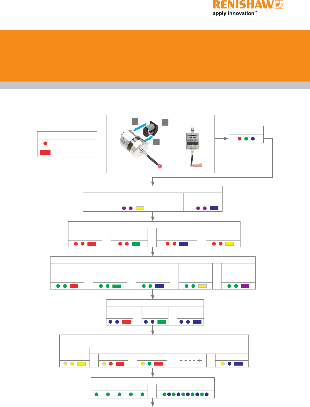
4.1
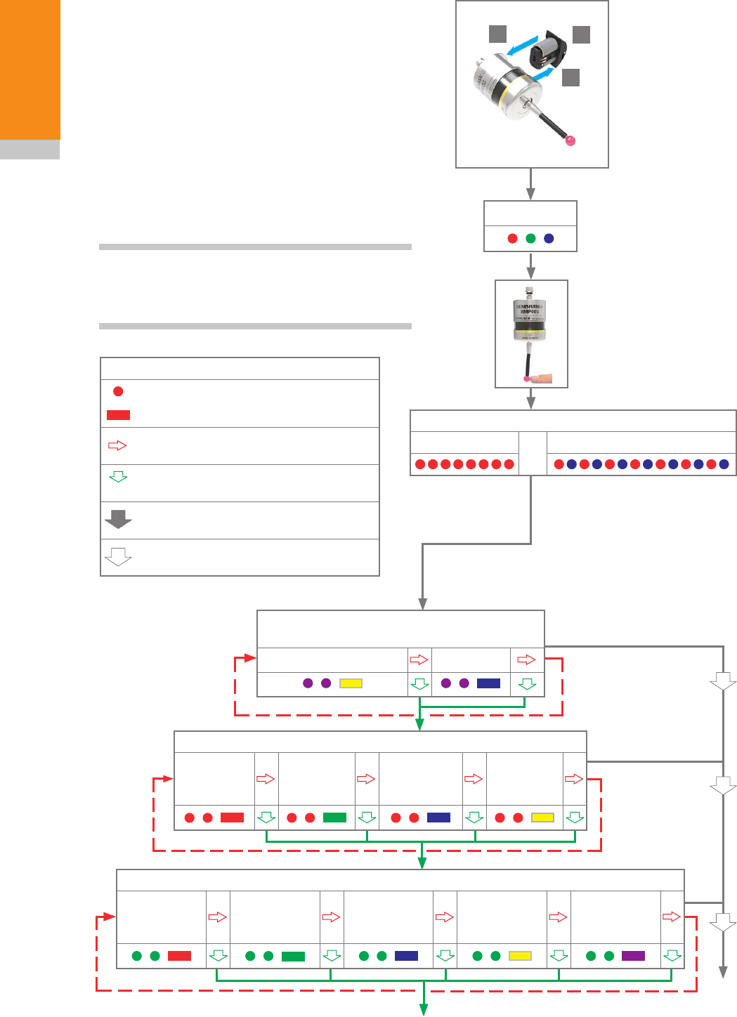
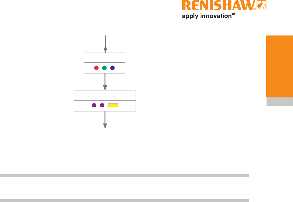
Key to the symbols
LED short flash
LED long flash
Switch-on method
Radio on
(omitted if “multiple probe mode” is selected) or
Spin on
Switch-off method
Radio off or
Spin off or
Short timeout
12 s or
Medium timeout
33 s or
Long timeout
134 s
LED check
Probe in standby mode (after 5 seconds)
Enhanced trigger filter and auto-reset facility
Auto-reset off
Trigger filter
on 8 ms or
Auto-reset off
Trigger filter
on 16 ms or
Auto-reset on
Trigger filter
on 8 ms or
Auto-reset on
Trigger filter
on 16 ms or
Auto-reset off
Trigger filter
off
Battery status
Battery good or Battery low
Multiple probe mode (omitted for “radio on”)
see “Multiple probe mode settings” to view all 16 choices
Mode off Mode on
or Machine 1 or Machine 2 or or Machine 16
Reviewing the probe settings
Trigger Logic™
see Section 4, “Trigger Logic™”
Hibernation mode (only for “radio on”)
On
30 s or
On
5 s or Off
1
> 5 s
2
3
Draft 5 16/04/18
RMP400 installation guide
4.2
Trigger Logic
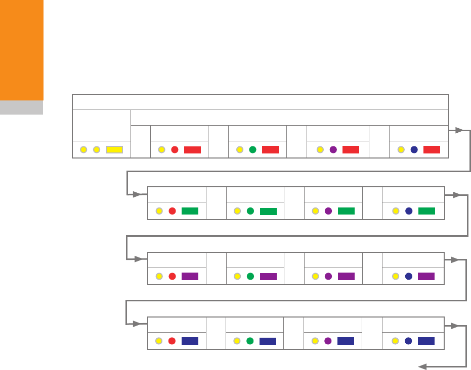
Multiple probe mode settings
Deflect the stylus for less than 4 seconds to cycle
to the next setting.
Multiple probe mode
Mode off Mode on
or Machine 1 or Machine 2 or Machine 3 or Machine 4
Machine 5 or Machine 6 or Machine 7 or Machine 8
Machine 9 or Machine 10 or Machine 11 or Machine 12
Machine 13 or Machine 14 or Machine 15 or Machine 16
Return to
“Mode off”
Draft 5 16/04/18

4.3
Trigger Logic
Factory
settings
New
settings
Switch-on method Radio on
Spin on
Switch-off method Radio or spin
Short timeout (12 s)
Medium timeout (33 s)
Long timeout (134 s)
Auto-reset and
enhanced trigger filter
Auto reset off /
Trigger filter on (8 ms)
Auto reset off /
Trigger filter on (16 ms)
Auto reset on /
Trigger filter on (8 ms)
Auto reset on /
Trigger filter on (16 ms)
Auto reset off / Trigger filter off
Hibernation mode On (30 s)
On (5 s)
Off
Multiple probe mode Off (factory set)
On (machine number) See “Multiple
probe settings”
RMP400 serial no ........................................
tick
Probe settings record
This page is provided to note your probe’s
settings. tick
Factory settings are for kit (A-6570-0001) only.
Draft 5 16/04/18
RMP400 installation guide
4.4
Trigger Logic
LED check
1
> 5 s
2
3
Probe partnering function
The probe partnering function enables the
RMP400 to be partnered with the RMI or RMI-Q
independently of the configuration process for
other probe settings. To partner RMP400 with
RMI or RMI-Q, insert the batteries or, if they
have already been installed, remove them for five
seconds and then refit them.
Following an LED check, the RMP400 will
proceed to show the probe settings, this will end
with “Probe status” being displayed. If the battery
power is good, probe status will be eight green
flashes. If battery power is low, each green flash
will be followed by a blue flash.
Key to the symbols
LED short flash
LED long flash
Deflect the stylus for less than 4 seconds
to move to the next menu option.
To exit, leave the stylus untouched for
more than 120 seconds.
Acquisition successful. Probe is now in
standby.
Whilst the “Probe status” is being displayed,
deflect and immediately release the stylus to
enter “Acquisition mode”.
“Acquisition mode off” will be displayed as a
sequence of light blue flashes, at this point the
RMI or RMI-Q must be turned on.
On the RMP400 select “Acquisition mode on”
by deflecting the stylus for less than 4 seconds.
After a successful acquisition, the RMP400 will
timeout after 8 seconds and then go into standby.
If “Acquisition mode on” is not selected, the
RMP400 will timeout after 120 seconds and then
go into standby (see page 4.10, “RMP400 – RMI
partnership”) or (see page 4.11, “RMP400 –
RMI-Q partnership”).
Probe status (seated)
Battery good or Battery low
Probe status
Battery good
or
Battery low
Whilst the “Probe status” is being displayed,
deflect and release the stylus to enter
“Acquisition mode off”. Probe status will flash
red to acknowledge this.
At this point turn on either the RMI or RMI-Q.
All probe settings will be shown, ending
with “Probe status” being displayed.
Draft 5 16/04/18
4.5
Trigger Logic
Acquisition mode
Acquisition mode off Acquisition mode on
8 seconds
probe in standby
120 seconds
probe in standby
After 8
seconds
If acquisition is unsuccessful “Acquisition mode off” will be
displayed again after 8 seconds.
Deflect the stylus for less than 4 seconds to select “Acquisition
mode on” again.
Acquisition
successful
Draft 5 16/04/18
RMP400 installation guide
4.6
Trigger Logic
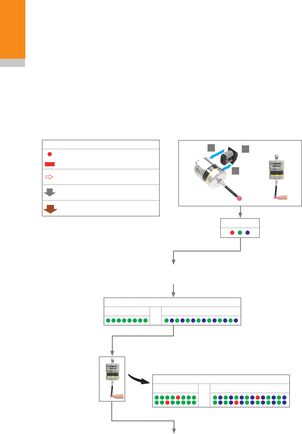
Key to the symbols
LED short flash
LED long flash
Deflect the stylus for less than 4 seconds
to move to the next menu option.
Deflect the stylus for more than
4 seconds to move to the next menu.
To exit, leave the stylus untouched for
more than 120 seconds.
To exit, leave the stylus untouched for
more than 20 seconds.
LED check
Probe status (triggered)
Battery good or Battery low
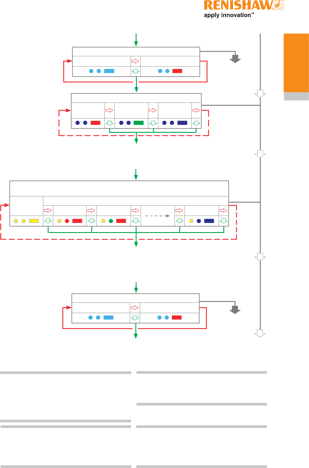
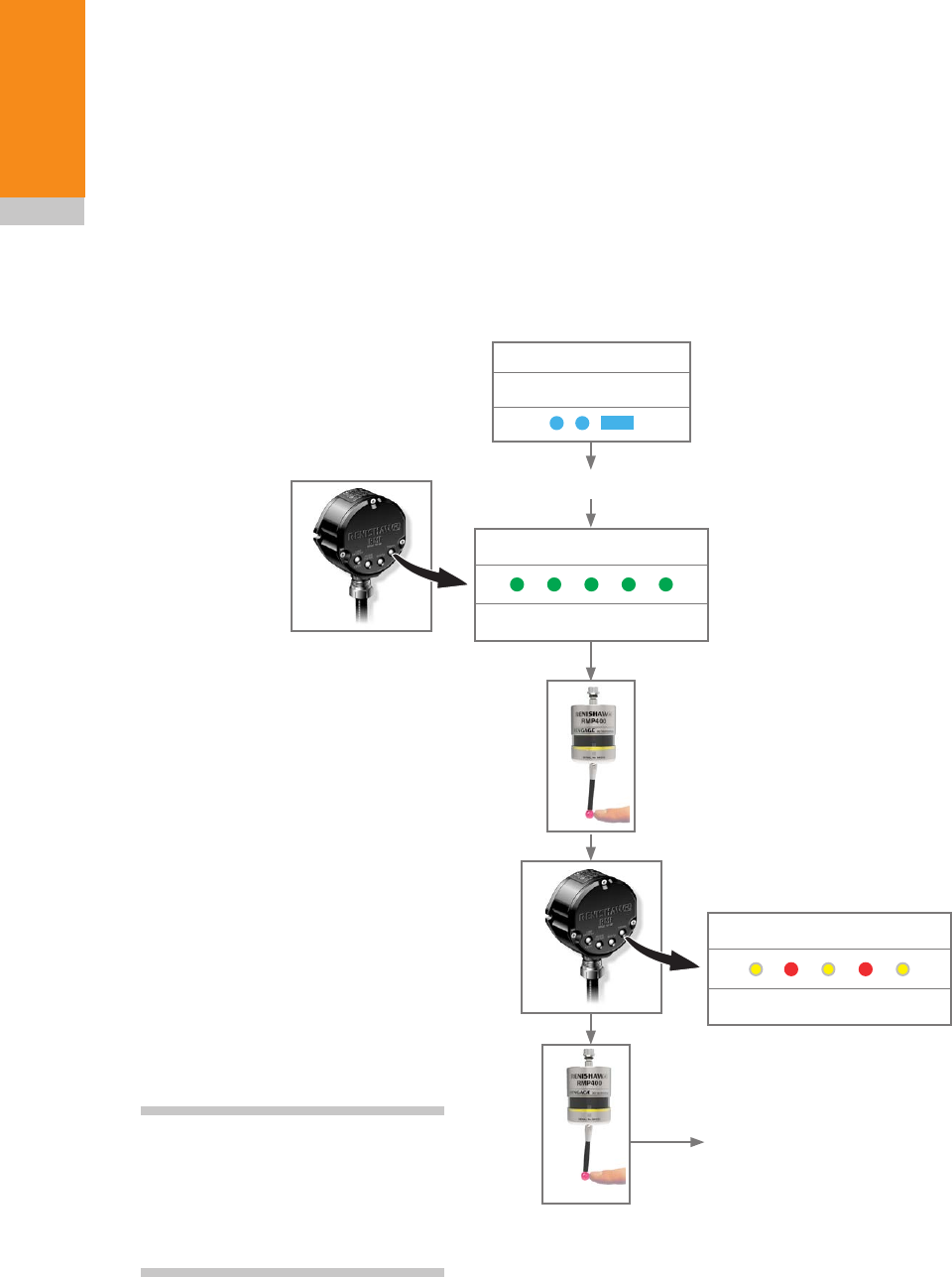
Changing the probe settings
Insert the batteries or, if they have already been
installed, remove them for five seconds and then
refit them.
Following the LED check, immediately deflect the
stylus and hold it deflected until eight red flashes
have been observed (if the battery power is low,
each red flash will be followed by a blue flash).
Keep the stylus deflected until the “Switch-on
method” setting is displayed, then release it.
CAUTION: Do not remove the batteries whilst
in configuration mode. To exit, leave the stylus
untouched for more than 20 seconds.
Switch-off method
Radio off or
Spin off
Short
timeout
12 s
Medium
timeout
33 s
Long
timeout
134 s
Switch-on method
(omitted if “multiple probe mode” was selected)
Radio on Spin on
Enhanced trigger filter setting and auto-reset facility
Auto reset off
Trigger filter
on 8 ms
Auto reset off
Trigger filter
on 16 ms
Auto reset on
Trigger filter
on 8 ms
Auto reset on
Trigger filter
on 16 ms
Auto reset off
Trigger filter
off
> 5 s
12
3
Draft 5 16/04/18
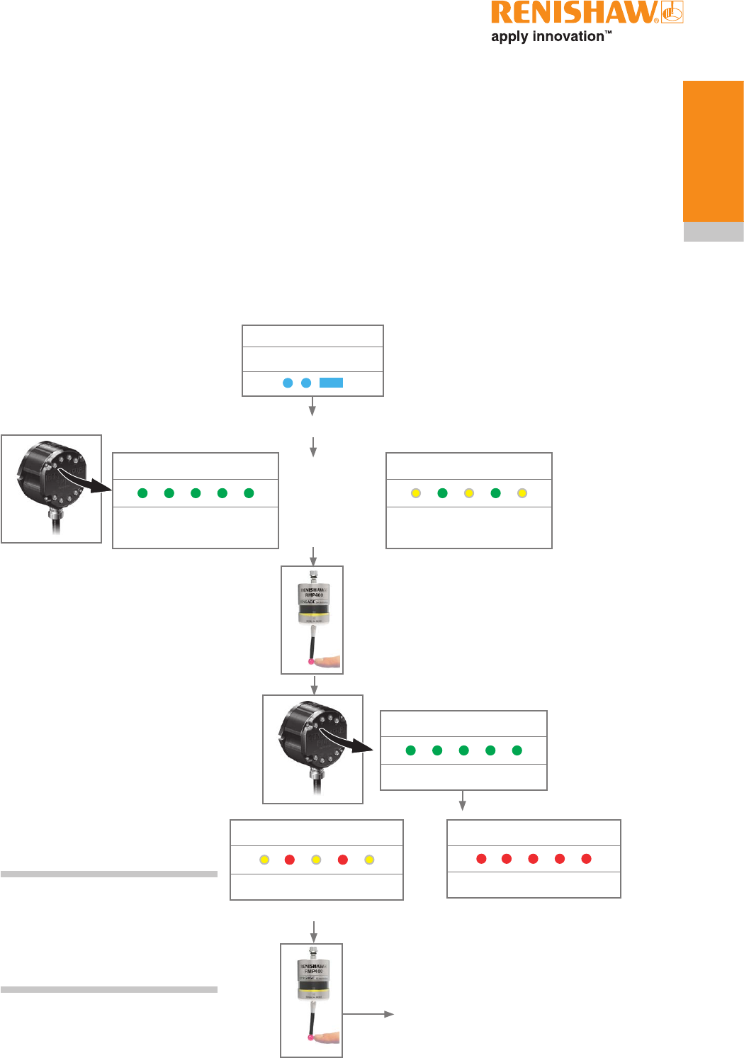
4.7
Trigger Logic
Stop triggering here, unless “Multiple probe
mode” is required, in which case deflect the
stylus for more than 4 seconds.
New settings
complete,
probe in
standby
If no changes are made in “Multiple probe mode”, then deflecting the
stylus for more than 4 seconds will return the probe settings to beginning
of the Trigger Logic menu. If “Multiple probe mode” is selected, proceed to
“Acquisition mode” to repartner one probe with the RMI-Q.
Return to the beginning of the Trigger Logic menu
Multiple probe mode (omitted for “radio on”)
(see “Multiple probe mode settings” to view all 16 choices)
Mode off Mode on
Machine 1 Machine 2
Machine 16
Hibernation mode (only for “radio on”)
On
30 s
On
5 s
Off
NOTE: Further probes used require the same
“Multiple probe mode” setting, but do not need
to be partnered with the RMI or RMI-Q.
NOTE: If using “Multiple probe mode”, refer
to the installation guide RMI radio machine
interface (Renishaw part no. H-4113-8554) or the
installation guide RMI-Q radio machine interface
(Renishaw part no. H-5687-8504).
NOTE: To partner an RMP400 with an RMI-Q
please see “RMP400 – RMI-Q partnership”. Once
acquisition has been successful, the RMP400 will
revert to “Acquisition mode off”.
NOTE: To partner an RMP400 with an RMI
please see “RMP400 – RMI partnership”. Once
acquisition has been successful, the RMP400 will
revert to “Acquisition mode off”.
Acquisition mode
Acquisition mode off Acquisition mode on
Acquisition mode
Acquisition mode off Acquisition mode on
120 seconds
probe in standby
120 seconds
probe in standby
Draft 5 16/04/18
RMP400 installation guide
4.8
Trigger Logic
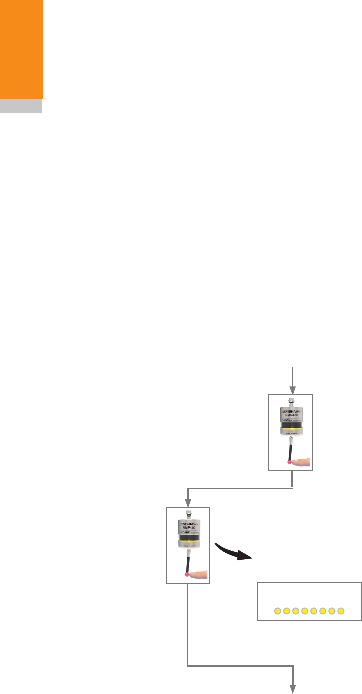
Master reset function
RMP400 features a master reset function to assist
user’s who have mistakenly changed the probe
settings into an unintended state.
The application of the master reset function will
clear all current probe settings and return the
probe to default settings.
The default settings are as follows:
• Radio switch-on
• Radio switch-off
• Auto-reset on, Enhanced trigger filter on 8 ms
• Hibernation mode on 30 s
• Multiple probe mode off
The default settings may not be representative of
the required probe settings. Further configuration
of RMP400 may subsequently be necessary to
achieve the required probe settings.
To reset the probe
1. First enter into the Trigger Logic™ menu and
ensure that the stylus is no longer deflected.
2. From within the Trigger Logic menu, hold the
stylus deflected for 20 seconds. After this
the status LEDs will proceed to flash yellow
eight times. A confirmation for master reset
is required, if nothing is done the probe will
timeout.
To confirm that a master reset is required,
release the stylus and then hold the stylus
deflected again until the eight yellow flash
sequence has ended. This action will clear
all probe settings and return the probe to
default settings. Following an LED check the
RMP400 will then go back into Trigger Logic
and will display “Switch-on method”.
3. Further configuration using Trigger Logic may
be necessary to achieve the required probe
settings.
1. Probe is in the Trigger Logic menu.
Ensure that the stylus is no longer deflected.
Whilst the status LEDs are flashing yellow to confirm that
a master reset is required, release the stylus and then
hold the stylus deflected again until the eight yellow flash
sequence has ended.
System status LED
Deflect the stylus for 20 seconds until the
status LEDs start to flash yellow eight times.
2.
Previous settings have been cleared.
The probe now has default settings.
Draft 5 16/04/18
4.9
Trigger Logic
LED check
Switch-on method
Probe is now back in the Trigger
Logic menu and will display
“Switch-on method”.
Configure probe settings as required
using Trigger Logic
3.
NOTE: RMP400 will continue to be partnered with either the RMI or RMI-Q following the
activation of the master reset function, unless “Multiple probe mode” has been used.
Draft 5 16/04/18
4.10
Trigger Logic
RMP400 – RMI partnership
System set-up is achieved using Trigger Logic
and powering the RMI. Partnering is only required
during initial system set-up. Further partnering
will be required if either the RMP400 or RMI
is changed, or if a system is reconfigured for
multiple probes (multiple probe mode).
Deflect the stylus to select “Acquisition
mode on”. Ensure this is done within
8 seconds of the RMI signal LED
flashing green.
The probe is now in standby
and the system is ready for use.
Partnering will not be lost by reconfiguring the
probe settings or when changing batteries, except
where multiple probe mode is selected. Partnering
can take place anywhere within the operating
envelope.
In configuration mode, configure the probe
settings as required until you reach the
“Acquisition mode” menu, which defaults to
“Acquisition mode off”.
SIGNAL LED
RMI in acquisition mode
SIGNAL LED
New partner RMP acquired
Acquisition mode
Acquisition mode off
Switch the RMI on
NOTE: Please refer to the
installation guide RMI radio
machine interface (Renishaw part
no. H-4113-8554) when partnering
the RMP400.
> 20 s
Draft 5 16/04/18
4.11
Trigger Logic
RMP400 – RMI-Q partnership
System set-up is achieved by using Trigger Logic
and powering on the RMI-Q or applying ReniKey.
Partnering is required during initial system set-up.
Further partnering will be required if either the
RMP400 or RMI-Q is changed.
Partnering will not be lost by reconfiguring
the probe settings or changing the batteries.
Partnering can take place anywhere within the
operating envelope.
Deflect the stylus to select “Acquisition
mode on”. Ensure this is done within 60
seconds of the RMI-Q system status
LED flashing green.
The probe is now in standby
and the system is ready for use.
An RMP400 that is partnered with the RMI-Q
but then used with another system will need to
be repartnered before being used again with the
RMI-Q.
In configuration mode, configure the probe
settings as required until you reach the
“Acquisition mode” menu, which defaults to
“Acquisition mode off”.
SYSTEM STATUS LED
RMI-Q in acquisition mode
with empty probe location
SYSTEM STATUS LED
New partner RMP acquired
Acquisition mode
Acquisition mode off
Switch the RMI-Q on
SYSTEM STATUS LED
RMI-Q in acquisition mode
with full probe location
or
SYSTEM STATUS LED
Acquisition pending
or
SYSTEM STATUS LED
RMP cleared from location
Displayed for 5 seconds
NOTE: Please refer to the
installation guide RMI-Q radio
machine interface (Renishaw part
no. H-5687-8504) when partnering
up to four RMPs.
> 20 s
Draft 5 16/04/18
4.12
Trigger Logic
Operating mode
NOTE: Due to the nature of lithium-thionyl
chloride batteries, if a “low battery” LED warning is
ignored, it is possible for the following sequence of
events to occur:
1. When the probe is active, the batteries
discharge until battery power becomes too
low for the probe to operate correctly.
2. The probe stops functioning, but then
reactivates as the batteries recover
sufficiently to provide the probe with power.
3. The probe begins to run through the LED
review sequence (see page 4.1, “Reviewing
the probe settings”).
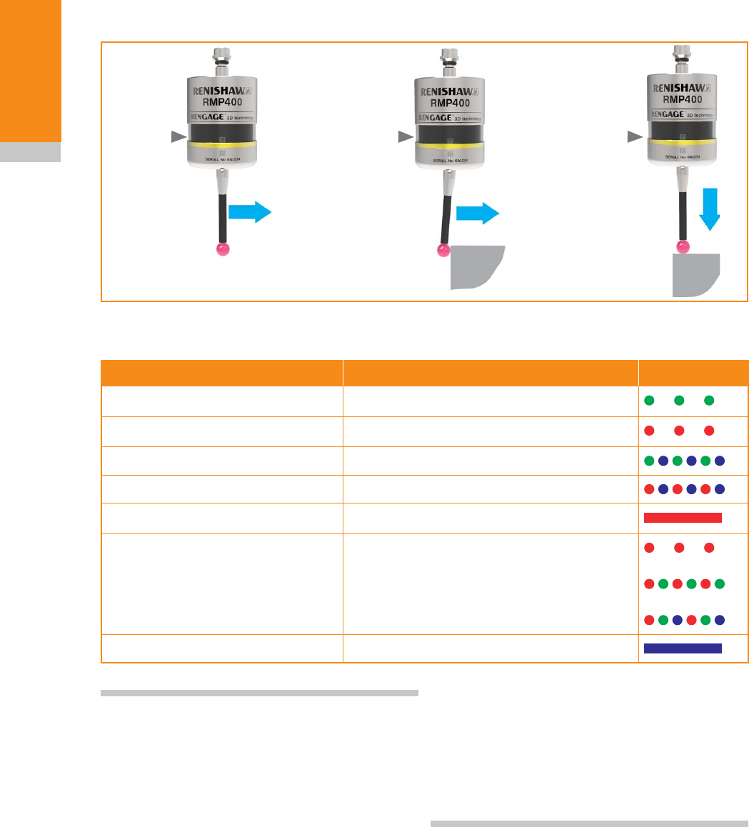
LED colour Probe status Graphic hint
Flashing green Probe seated in operating mode
Flashing red Probe triggered in operating mode
Flashing green and blue Probe seated in operating mode – low battery
Flashing red and blue Probe triggered in operating mode – low battery
Constant red Battery dead
Flashing red
or
Flashing red and green
or
Sequence when batteries are inserted
Unsuitable battery
Constant blue Probe damaged beyond use
LEDs
flashing
green
LEDs
flashing
red
LEDs
flashing
red
X/Y
Z
Probe status LEDs
4. Again, the batteries discharge and the probe
ceases to function.
5. Again, the batteries recover sufficiently
to provide the probe with power, and the
sequence repeats itself.
Draft 5 16/04/18

5.1
Maintenance
You may undertake the maintenance routines
described in these instructions.
Further dismantling and repair of Renishaw
equipment is a highly specialised operation, which
must be carried out at an authorised Renishaw
Service Centre.
Equipment requiring repair, overhaul or attention
under warranty should be returned to your
supplier.
Cleaning the probe
Wipe the window of the probe with a clean cloth
to remove machining residue. This should be
done on a regular basis to maintain optimum
transmission.
Maintenance
CAUTION: The RMP400 has a glass window.
Handle with care if broken to avoid injury.
see Section 5,“Maintenance”
Draft 5 16/04/18
5.2
Maintenance
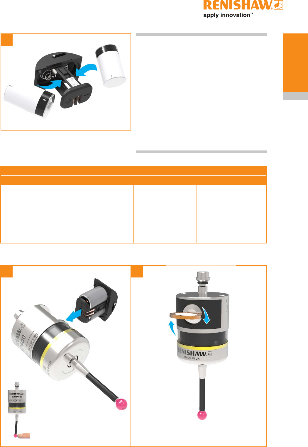
1
2
CAUTIONS:
Do not leave dead batteries in the probe.
When changing batteries, do not allow coolant or
debris to enter the battery compartment.
When changing batteries, check that the battery
polarity is correct.
Take care to avoid damaging the battery cassette
gasket.
Only use specified batteries.
Changing the batteries
CAUTION: Please dispose of dead batteries in
accordance with local regulations. Never dispose
of batteries in a fire.
Draft 5 16/04/18
5.3
Maintenance
NOTES:
After removing the old batteries, wait more than
5 seconds before inserting the new batteries.
Do not mix new and used batteries or battery
types, as this will result in reduced life and
damage to the batteries.
Always ensure that the cassette gasket and
mating surfaces are clean and free from dirt
before reassembly.
If dead batteries are inadvertently inserted, the
LEDs will remain a constant red.
3
45
Battery type
½ AA lithium-thionyl chloride (3.6 V) × 2
Ecocel
Saft:
Tadiran:
Xeno:
EB1426
LS 14250C
LS 14250
SL-750
XL-050F
Dubilier:
Maxell:
Sanyo
Tadiran:
Varta:
SB-AA02
ER3S
CR 14250SE
SL-350, SL-550,
TL-4902, TL-5902,
TL-2150, TL-5101
CR ½AA
Draft 5 16/04/18

5.4
Maintenance
This page is intentionally left blank.
Draft 5 16/04/18

6.1
Symptom Cause Action
Probe fails to
power up (no LEDs
illuminated or fails
to indicate current
probe settings).
Dead batteries. Change batteries.
Unsuitable batteries. Fit suitable batteries.
Batteries inserted incorrectly. Check battery insertion/polarity.
Batteries removed for too short a time
and probe has not reset.
Remove batteries for a minimum
of 5 seconds.
Poor connection between battery
cassette mating surfaces and
contacts.
Remove any dirt and clean the
contacts before reassembly.
Probe fails to
switch on.
Dead batteries. Change batteries.
Batteries inserted incorrectly. Check battery insertion/polarity.
Probe out of range. Check position of RMI or RMI-Q,
(see operating envelope).
No RMI or RMI-Q “start/stop” signal
(“radio on” method only).
Check RMI or RMI-Q for green
start LED.
Incorrect spin speed (“spin on”
method only).
Check spin speed and duration.
Incorrect switch on method
configured.
Check configuration and alter as
required.
Incorrect multiple probe mode setting
configured.
Check configuration and alter as
required.
RMP400 in hibernation mode (radio
on method only).
Ensure probe is in range and wait
up to 30 seconds, then resend
switch-on signal.
Check position of RMI or RMI-Q,
see operating envelope.
Spin on is within 1 second of spin off. Check for 1 second dwell following
spin off.
Fault-finding
see Section 6,“Fault-finding”
Draft 5 16/04/18

6.2
Fault-finding
Symptom Cause Action
Machine stops
unexpectedly during a
probing cycle.
Radio link failure/RMP400 out of
range.
Check interface/receiver and
remove obstruction.
RMI or RMI-Q receiver/machine
fault.
Refer to receiver/machine user’s
guide.
Dead batteries. Change batteries.
Excessive machine vibration
causing false probe trigger.
Enable enhanced trigger filter.
Probe unable to find target
surface.
Check that part is correctly
positioned and that stylus has not
broken.
Adjacent probe. Reconfigure adjacent probe to low
power mode and reduce range of
receiver.
Stylus not given sufficient time to
settle from a rapid deceleration.
Add a short dwell before the
probing move (length of dwell will
depend on stylus length and rate
of deceleration). Maximum dwell is
one second.
Probe crashes. Workpiece obstructing probe path. Review probing software.
Probe length offset missing Review probing software.
In cases where there is more than
one probe on a machine, incorrect
probe activated.
Review interface wiring or part
program.
Probe permanently
triggered.
Probe orientation has changed –
i.e. from horizontal to vertical.
Select probe “Auto-reset” function.
New stylus has been fitted. Turn probe off and on again.
Probe was switched on when
stylus was deflected.
Turn probe off and on again.
Ensure stylus is seated during
switch on.
Probe has not settled before a
trigger move occurs following a
rotation or rapid move (“Auto-
reset” mode only).
Turn probe off and on again, and
increase the dwell from 0.2 to
0.5 second dwell before probing
move.
Probe has collided with an object
during a rotation or rapid move
(“Auto-reset” mode only).
Turn probe off and on again.
Draft 5 16/04/18

6.3
Fault-finding
Symptom Cause Action
Poor probe repeatability
and/or accuracy.
Debris on part or stylus. Clean part and stylus.
Poor tool change repeatability. Redatum probe after each tool
change.
Loose probe mounting on shank
or loose stylus.
Check and tighten as appropriate.
Excessive machine vibration. Enable enhanced trigger filter.
Eliminate vibrations.
Calibration out of date and/or
incorrect offsets.
Review probing software.
Calibration and probing speeds
not the same.
Review probing software.
Calibration feature has moved. Correct the position.
Measurement occurs as stylus
leaves surface.
Review probing software.
Measurement occurs within
the machine’s acceleration and
deceleration zone.
Review probing software and
probe filter settings.
Probing speed too high or too
slow.
Perform simple repeatability trials
at various speeds.
Temperature variation causes
machine and workpiece
movement.
Minimise temperature changes.
Machine tool faulty. Perform health checks on
machine tool.
RMP400 status LEDs do
not correspond to RMI
or RMI-Q status LEDs.
Radio link failure – RMP400 out
of RMI or RMI-Q range.
Check position of RMI or RMI-Q,
see operating envelope.
RMP400 has been enclosed/
shielded by metal.
Remove from obstruction.
RMP400 and RMI or RMI-Q are
not partnered.
Partner RMP400 and RMI or
RMI-Q.
Draft 5 16/04/18

6.4
Fault-finding
Symptom Cause Action
RMI or RMI-Q error LED
lit during probing cycle.
Probe not switched on or probe
timed out.
Change setting. Review switch-off
method.
Probe out of range. Check position of RMI or RMI-Q,
see operating envelope.
Dead batteries. Change batteries.
RMP400 and RMI or RMI-Q are
not partnered.
Partner RMP400 with RMI or
RMI-Q.
Probe selection error. Verify that one RMP is working
and is correctly selected.
“Fast” turn-on error. Ensure that all RMPs are ‘Q’
marked probes, or change the
RMI-Q turn-on time to “standard”.
RMI or RMI-Q low
battery LED lit.
Low batteries. Change batteries soon.
Reduced range. Local radio interference. Identify and remove.
Probe fails to switch off. Incorrect “switch-off” method
configured.
Check configuration and alter as
required.
No RMI or RMI-Q “start/stop”
signal (“radio on” method only).
Check RMI or RMI-Q for green
start LED.
Probe in timeout mode and
placed in tool magazine and
being triggered by movement.
Use shorter timeout setting or use
different switch-off method.
Incorrect spin speed (spin switch
on only).
Check spin speed.
Spin off is within 1 second of a
spin on
Check for a 1 second dwell
following a spin on.
Probe goes into Trigger
Logic™ configuration
mode and cannot be
reset.
Probe was triggered when
batteries were inserted.
Do not touch the stylus or stylus
mounting face during battery
insertion.
Probe status LED shows
a constant blue
Probe damaged beyond use. Return the probe to your nearest
Renishaw supplier for repair/
replacement.
Draft 5 16/04/18

7.1
Item Part number Description
RMP400 A-6570-0001 RMP400 probe with batteries, tool kit and quick-start guide
(factory-set to radio on/radio off).
Battery P-BT03-0007 ½AA battery – lithium-thionyl chloride (pack of two).
Stylus A-5003-7306 50.0 mm (1.97 in) long carbon fibre stylus with Ø6.0 mm
(0.24 in) ball.
Stylus A-5003-6510 100.0 mm (3.94 in) long carbon fibre stylus with Ø6.0 mm
(0.24 in) ball.
Stylus A-5003-6511 150.0 mm (5.91 in) long carbon fibre stylus with Ø6.0 mm
(0.24 in) ball.
Stylus A-5003-6512 200.0 mm (7.88 in) long carbon fibre stylus with Ø6.0 mm
(0.24 in) ball.
Tool kit A-4071-0060 Probe tool kit comprising Ø1.98 mm stylus tool,
2.00 mm AF hexagon key and shank grub screw (× 6).
Battery cassette A-4071-0031 Battery cassette assembly.
Battery gasket A-4038-0301 Battery cap gasket kit.
RMI A-4113-0050 RMI (side exit) with 15 m (49.2 ft) cable, tool kit and user’s
guide.
RMI-Q A-5687-0050 RMI-Q (side exit) with 15 m (49.2 ft) cable, tool kit and
quick-start guide.
Mounting bracket A-2033-0830 Mounting bracket with fixing screws, washers and nuts.
Styli tool M-5000-3707 Tool for tightening/releasing styli.
Publications. These can be downloaded from our web site at www.renishaw.com.
RMP400 H-6570-8500 Quick-start guide: for rapid set-up of the RMP400 probe.
RMI QSG A-4113-8550 Quick-start guide: for rapid set-up of the RMI.
RMI IG H-4113-8554 Installation guide: for set-up of the RMI.
RMI-Q QSG H-5687-8500 Quick-start guide: for rapid set-up of the RMI-Q.
RMI-Q IG H-5687-8504 Installation guide: for set-up of the RMI-Q.
Styli H-1000-3200 Technical specifications guide: Styli and accessories – or visit
our Web shop at www.renishaw.com/shop.
Probe software H-2000-2298 Data sheet: Probe software for machine tools – programs and
features.
Taper shanks H-2000-2011 Data sheet: taper shanks for machine tool probes.
Parts list
see Section 7,“Parts list”
Draft 5 16/04/18

Renishaw plc
New Mills, Wotton-under-Edge
Gloucestershire, GL12 8JR
United Kingdom
T +44 (0)1453 524524
F +44 (0)1453 524901
E uk@renishaw.com
www.renishaw.com
For worldwide contact details, visit
www.renishaw.com/contact
*H-6570-8501-01*
© 2018 Renishaw plc
Issued: ??.????
Part no. H-6570-8501-01-A
Draft 5 16/04/18